All contents are Copyright © 1992–2007 Cisco Systems, Inc. All rights reserved. This document is Cisco Public Information.
Page 1 of 9
CCNA Exploration: Accessing the WAN Student Skills Based
Assessment Lab
Answer Key
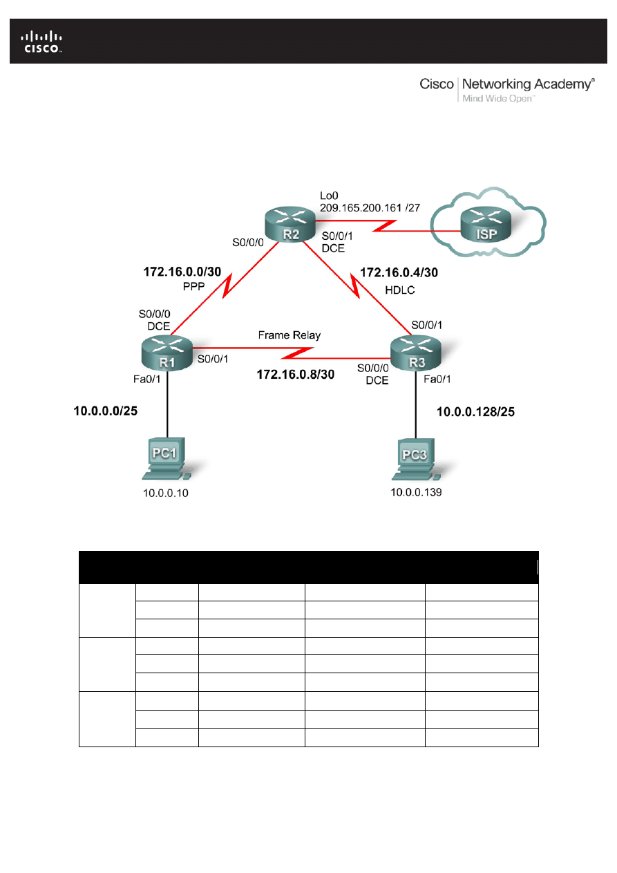
Topology Diagram
Addressing Table
Device
Interface
IP Address
Subnet Mask
Default Gateway
R1
Fa0/1
10.0.0.1
255.255.255.128
N/A
S0/0/0
172.16.0.1
255.255.255.252
N/A
S0/0/1
172.16.0.9
255.255.255.252
N/A
R2
Lo0
209.165.200.161
255.255.255.224
N/A
S0/0/0
172.16.0.2
255.255.255.252
N/A
S0/0/1
172.16.0.5
255.255.255.252
N/A
R3
Fa0/1
10.0.0.129
255.255.255.128
N/A
S0/0/0
172.16.0.10
255.255.255.252
N/A
S0/0/1
172.16.0.6
255.255.255.252
N/A

CCNA Exploration
Accessing the WAN: Skills Based Assessment
Student Skills based Assessment Lab
All contents are Copyright © 1992–2007 Cisco Systems, Inc. All rights reserved. This document is Cisco Public Information.
Page 2 of 9
Device
Interface
IP Address
Subnet Mask
Default Gateway
PC1
NIC
10.0.0.10
255.255.255.128
10.0.0.1
PC3
NIC
10.0.0.139
255.255.255.128
10.0.0.129
Learning Objectives
To complete this lab:
• Cable a network according to the topology diagram
• Erase the startup configuration and reload a router to the default state
• Perform basic configuration tasks on a router
• Configure and activate interfaces
• Configure and activate serial interfaces (PPP with CHAP, HDLC, and Frame Relay)
• Configure RIP on all the routers
• Configure basic router security
• Configure ACLs
• Configure basic NAT
Scenario
This lab tests you on the skills and knowledge that you learned in Exploration 4. Use cisco for all passwords in
this lab, except for the enable secret password, which is class.
Task 1: Prepare the Network
Step 1: Cable a network that is similar to the one in the topology diagram.
Step 2: Clear any existing configurations on the routers.
Task 2: Perform Basic Device Configurations
Configure the R1, R2, and R3 routers according to the following guidelines:
• Configure the router hostname.
• Disable DNS lookup.
• Configure an EXEC mode password.
• Configure a message-of-the-day banner.
• Configure a password for console connections.
• Configure synchronous logging.
• Configure a password for vty connections.
R1:
Router>enable
Router#configure terminal
Router(config)#hostname R1
R1(config)#banner motd #R1#
R1(config)#no ip domain-lookup
R1(config)#enable secret class

CCNA Exploration
Accessing the WAN: Skills Based Assessment
Student Skills based Assessment Lab
All contents are Copyright © 1992–2007 Cisco Systems, Inc. All rights reserved. This document is Cisco Public Information.
Page 3 of 9
R1(config)#line console 0
R1(config-line)#password cisco
R1(config-line)#login
R1(config-line)#logging synchronous
R1(config-line)#exec-timeout 5
R1(config-line)#exit
R1(config)#line vty 0 4
R1(config-line)#password cisco
R1(config-line)#login
R1(config-line)#logging synchronous
R1(config-line)#exec-timeout 5
R1(config-line)#exit
R2:
Router>enable
Router#configure terminal
Router(config)#hostname R2
R2(config)#banner motd #R2#
R2(config)#no ip domain-lookup
R2(config)#enable secret class
R2(config)#line console 0
R2(config-line)#password cisco
R2(config-line)#login
R2(config-line)#logging synchronous
R2(config-line)#exec-timeout 5
R2(config-line)#exit
R2(config)#line vty 0 4
R2(config-line)#password cisco
R2(config-line)#login
R2(config-line)#logging synchronous
R2(config-line)#exec-timeout 5
R2(config-line)#exit
R3:
Router>enable
Router#configure terminal
Router(config)#hostname R3
R3(config)#banner motd #R3#
R3(config)#no ip domain-lookup
R3(config)#enable secret class
R3(config)#line console 0
R3(config-line)#password cisco
R3(config-line)#login
R3(config-line)#logging synchronous
R3(config-line)#exec-timeout 5
R3(config-line)#exit

CCNA Exploration
Accessing the WAN: Skills Based Assessment
Student Skills based Assessment Lab
All contents are Copyright © 1992–2007 Cisco Systems, Inc. All rights reserved. This document is Cisco Public Information.
Page 4 of 9
R3(config)#line vty 0 4
R3(config-line)#password cisco
R3(config-line)#login
R3(config-line)#logging synchronous
R3(config-line)#exec-timeout 5
R3(config-line)#exit
Task 3: Configure and Activate Serial and Ethernet Addresses
Step 1: Configure interfaces on R1, R2, and R3.
Step 2: Verify IP addressing and interfaces.
Step 3: Configure the PC1 and PC3 Ethernet interfaces.
Step 4: Test connectivity between the PCs and routers.
R1:
R1(config)#interface fastEthernet0/1
R1(config-if)#ip address 10.0.0.1 255.255.255.128
R1(config-if)#no shutdown
R1(config-if)#exit
R1(config)#interface Serial0/0/0
R1(config-if)#ip address 172.16.0.1 255.255.255.252
R1(config-if)#clock rate 64000
R1(config-if)#no shutdown
R1(config-if)#exit
R1(config)#interface Serial0/0/1
R1(config-if)#ip address 172.16.0.9 255.255.255.252
R1(config-if)#no shutdown
R1(config-if)#end
R1#show ip interface brief
R2:
R2(config)#interface Serial0/0/0
R2(config-if)#ip address 172.16.0.2 255.255.255.252
R2(config-if)#no shutdown
R2(config-if)#exit
R2(config)#interface Serial0/0/1
R2(config-if)#ip address 172.16.0.5 255.255.255.252
R1(config-if)#clock rate 64000
R2(config-if)#no shutdown
R2(config-if)#exit
R2(config)#interface Loopback0
R2(config-if)#ip address 209.165.200.161 255.255.255.224
R2(config-if)#no shutdown
R2(config-if)#end
R2#show ip interface brief

CCNA Exploration
Accessing the WAN: Skills Based Assessment
Student Skills based Assessment Lab
All contents are Copyright © 1992–2007 Cisco Systems, Inc. All rights reserved. This document is Cisco Public Information.
Page 5 of 9
R3:
R3(config)#interface fastEthernet0/1
R3(config-if)#ip address 10.0.0.129 255.255.255.128
R3(config-if)#no shutdown
R3(config-if)#exit
R3(config)#interface Serial0/0/0
R3(config-if)#ip address 172.16.0.10 255.255.255.252
R3(config-if)#clock rate 64000
R3(config-if)#no shutdown
R3(config-if)#exit
R3(config)#interface Serial0/0/1
R3(config-if)#ip address 172.16.0.6 255.255.255.252
R3(config-if)#no shutdown
R3(config-if)#end
R3#show ip interface brief
Task 4: Configure Serial Interfaces
Step 1: Configure and verify PPP encapsulation with CHAP authentication between R1 and R2. The
password is “cisco”.
Step 2: Configure and verify HDLC encapsulation between R2 and R3.
Step 3: Configure Frame Relay between R1 and R3.
R1:
R1#configure terminal
R1(config)#username R2 password cisco
R1(config)#interface Serial0/0/0
R1(config-if)#encapsulation ppp
R1(config-if)#ppp authentication chap
R1(config-if)#exit
R1(config)#interface Serial0/0/1
R1(config-if)#encapsulation frame-relay
R1(config-if)#frame-relay map ip 172.16.0.9 101 broadcast
R1(config-if)#frame-relay map ip 172.16.0.10 101 broadcast
R1(config-if)#frame-relay interface-dlci 101
R1(config-if)#no keepalive
R1(config-if)#end
R1#show interface Serial0/0/0
R1#show interface Serial0/0/1
R3#show frame-relay pvc
R3#show frame-relay map
R2:
R2#configure terminal
R2(config)#username R1 password cisco
R2(config)#interface Serial0/0/0
R2(config-if)#encapsulation ppp

CCNA Exploration
Accessing the WAN: Skills Based Assessment
Student Skills based Assessment Lab
All contents are Copyright © 1992–2007 Cisco Systems, Inc. All rights reserved. This document is Cisco Public Information.
Page 6 of 9
R2(config-if)#ppp authentication chap
R2(config-if)#exit
R2(config)#interface Serial0/0/1
R2(config-if)#encapsulation hdlc
R2(config-if)#end
R2#show interface Serial0/0/0
R2#show interface Serial0/0/1
R3:
R3#configure terminal
R3(config)#interface Serial0/0/0
R3(config-if)#encapsulation frame-relay
R3(config-if)#frame-relay map ip 172.16.0.10 101 broadcast
R3(config-if)#frame-relay map ip 172.16.0.9 101 broadcast
R3(config-if)#frame-relay interface-dlci 101
R3(config-if)#no keepalive
R3(config-if)#exit
R3(config)#interface Serial0/0/1
R3(config-if)#encapsulation hdlc
R3(config-if)#end
R3#show interface Serial0/0/0
R3#show interface Serial0/0/1
R3#show frame-relay pvc
R3#show frame-relay map
Task 5: Configure RIP
Step 1: Configure RIP on R1, R2, and R3.
RIP updates should only be sent on the serial links between the routers. Prevent all other RIP updates on
all networks.
Step 2: Test connectivity with the ping command.
Step 3: Verify the routing table with the appropriate command.
R1:
R1#configure terminal
R1(config)#router rip
R1(config-router)#version 2
R1(config-router)#network 10.0.0.0
R1(config-router)#network 172.16.0.0
R1(config-router)#passive-interface fastEthernet0/1
R1(config-router)#no auto-summary
R1(config-router)#end
R1#show ip protocols
R1#show ip route

CCNA Exploration
Accessing the WAN: Skills Based Assessment
Student Skills based Assessment Lab
All contents are Copyright © 1992–2007 Cisco Systems, Inc. All rights reserved. This document is Cisco Public Information.
Page 7 of 9
R2:
R2#configure terminal
R2(config)#ip route 0.0.0.0 0.0.0.0 Loopback0
R2(config)#router rip
R2(config-router)#version 2
R2(config-router)#network 172.16.0.0
R2(config-router)#no auto-summary
R2(config-router)#redistribute static
R2(config-router)#end
R2#show ip protocols
R2#show ip route
R3:
R3#configure terminal
R3(config)#router rip
R1(config-router)#version 2
R3(config-router)#network 10.0.0.0
R3(config-router)#network 172.16.0.0
R3(config-router)#passive-interface fastEthernet0/1
R3(config-router)#no auto-summary
R3(config-router)#end
R3#show ip protocols
R3#show ip route
Task 6: Configure Basic Router Security
Step 1: Enable a secure Telnet login using a local database on R2.
Step 2: Disable unused services and interfaces on R2.
Step 3: Confirm that R2 is secured.
R2:
R2#configure terminal
R2(config)#username cisco password cisco
R2(config)#aaa new-model
R2(config)#aaa authentication login LOCAL_AUTH local
R2(config)#line vty 0 4
R2(config-line)#login authentication LOCAL_AUTH
R2(config)#no service pad
R2(config)#no service finger
R2(config)#no service udp-small-server
R2(config)#no service tcp-small-server
R2(config)#no ip bootp server
R2(config)#no ip http server
R2(config)#no ip finger
R2(config)#no ip source-route
R2(config)#no ip gratuitous-arps

CCNA Exploration
Accessing the WAN: Skills Based Assessment
Student Skills based Assessment Lab
All contents are Copyright © 1992–2007 Cisco Systems, Inc. All rights reserved. This document is Cisco Public Information.
Page 8 of 9
R2(config)#no cdp run
Task 7: Configure Access Control Lists
Step 1: Allow telnet to R1 and R3 from R2 only.
Step 2: Do not allow HTTP, Telnet, and FTP traffic from the Internet to PC1.
Step 3: Do not allow PC1 to receive traffic from the 10.0.0.128 /25 network.
Step 4: Verify that PC3 cannot ping PC1, but can ping 10.0.0.1.
R1:
R1#configure terminal
R1(config)#access-list 101 permit tcp host 172.16.0.2 any eq 23
R1(config)#access-list 101 permit tcp host 172.16.0.5 any eq 23
R1(config)#access-list 101 deny tcp any any eq 23
R1(config)#access-list 101 permit ip any any
R1(config)#line vty 0 4
R1(config-line)#access-class 101 in
R1(config-line)#end
R1#show ip access-lists
R2:
R2#configure terminal
R2(config)#access-list 102 deny tcp any host 10.0.0.10 eq 80
R2(config)#access-list 102 deny tcp any host 10.0.0.10 eq 23
R2(config)#access-list 102 deny tcp any host 10.0.0.10 eq 21
R2(config)#access-list 102 deny tcp any host 10.0.0.10 eq 20
R2(config)#access-list 102 permit ip any any
R2(config)#interface Loopback0
R2(config-if)#ip access-group 102 in
R2(config-if)#end
R2#show ip access-lists
R3:
R3#configure terminal
R3(config)#access-list 101 permit tcp host 172.16.0.2 any eq 23
R3(config)#access-list 101 permit tcp host 172.16.0.5 any eq 23
R3(config)#access-list 101 deny tcp any any eq 23
R3(config)#access-list 101 permit ip any any
R3(config)#line vty 0 4
R3(config-line)#access-class 101 in
R3(config-line)#end
R3(config)#access-list 103 deny ip 10.0.0.128 0.0.0.127 host 10.0.0.10
R3(config)#access-list 103 permit ip any any

CCNA Exploration
Accessing the WAN: Skills Based Assessment
Student Skills based Assessment Lab
All contents are Copyright © 1992–2007 Cisco Systems, Inc. All rights reserved. This document is Cisco Public Information.
Page 9 of 9
R3(config)#interface Serial0/0/0
R3(config-if)#ip access-group 103 out
R3(config-if)#exit
R3(config)#interface Serial0/0/1
R3(config-if)#ip access-group 103 out
R3(config-if)#end
R3#show ip access-lists
Task 8: Configure NAT.
Step 1: Configure NAT to allow PC3 to ping PC1.
Step 2: Verify that PC3 can reach PC1.
R3:
R3#configure terminal
R3(config)#access-list 104 permit ip 10.0.0.128 0.0.0.127 any
R3(config)#ip nat inside source list 104 interface Serial0/0/0 overload
R3(config)#interface fastEthernet0/1
R3(config-if)#ip access-group 104 in
R3(config-if)#ip nat inside
R3(config-if)#exit
R3(config)#interface Serial0/0/0
R3(config-if)#ip nat outside
R3(config-if)#exit
R3(config)#interface Serial0/0/1
R3(config-if)#ip nat outside
R3(config-if)#end
R3#show ip access-lists
Task 9: Document the Router Configurations
Task 10: Clean Up
Erase the configurations and reload the routers. Disconnect and store the cabling. For PC hosts that are normally
connected to other networks, such as the school LAN or to the Internet, reconnect the appropriate cabling and
restore the TCP/IP settings.
Wyszukiwarka
Podobne podstrony:
Differences in the note taking skills of students with high achievement,
The Philosopher and the Wolf students
13 Interoperability, data discovery and access The e infrastructures for earth sciences resources
Distributed Algorithm for the Layout of VP based ATM Networks
ebook occult The Psychedelic Experience A manual based on the Tibetan Book of the Dead
skills based cv
Introduction To The WIN PROLOG 4 3 PDF Based Documentation
Breaking the Yardstick The Dangers of Market based Governance
Einstein the poor student
9004260 Korean Beginner S2 Lesson 18 The Lost Student Part 2 Graduation is TODAY
Skills based CV improved
The Business 2 0 Students Answer Key
więcej podobnych podstron