4012-0XX
Medley
TM
Lexmark and Medley are trademarks
of Lexmark International, Inc.,
registered in the United States and/or
other countries.
• Index

Second Edition (July, 1995)
The following paragraph does not apply to the United Kingdom or any country
where such provisions are inconsistent with local law: LEXMARK INTERNA-
TIONAL, INC. PROVIDES THIS PUBLICATION “AS IS” WITHOUT WAR-
RANTY OF ANY KIND, EITHER EXPRESS OR IMPLIED, INCLUDING, BUT
NOT LIMITED TO, THE IMPLIED WARRANTIES OF MERCHANTABILITY OR
FITNESS FOR A PARTICULAR PURPOSE. Some states do not allow dis-
claimer of express or implied warranties in certain transactions, therefore, this
statement may not apply to you.
This publication could include technical inaccuracies or typographical errors.
Changes are periodically made to the information herein; these changes will be
incorporated in later editions of the publication. Improvements or changes in the
products or the programs described in this publication may be made at any
time. Publications are not stocked at the address given below; requests for pub-
lications should be made to your point of purchase.
Comments may be addressed to Lexmark International, Inc., Department
D22A/035-3, 740 New Circle Road, Lexington, Kentucky 40550, U.S.A. Lex-
mark may use or distribute any of the information you supply in any way it
believes appropriate without incurring any obligation to you.
Lexmark and Medley are trademarks of Lexmark International, Inc.
ExecJet is a registered trademark of International Business Machines Corpora-
tion
© Copyright Lexmark International, Inc. 1995. All Rights Reserved.
UNITED STATES GOVERNMENT RESTRICTED RIGHTS
This software and documentation are provided with RESTRICTED RIGHTS.
Use, duplication or disclosure by the Government is subject to restrictions as
set forth in subparagraph (c)(1)(ii) of the Rights in Technical Data and Computer
Software clause at DFARS 252.227-7013 and in applicable FAR provisions:
Lexmark International, Inc., Lexington, KY 40550.
4012-0XX

iii
4012-0XX
Contents
1
Preface . . . . . . . . . . . . . . . . . . . . . . . . . . . . . . . . . . . . . . . . . . . vi
Safety Information. . . . . . . . . . . . . . . . . . . . . . . . . . . . . . . . . . . vii
General Information . . . . . . . . . . . . . . . . . . . . . . . . . . . . . . . . . . . . 1
Options . . . . . . . . . . . . . . . . . . . . . . . . . . . . . . . . . . . . . . . . . . . . 2
Maintenance Approach . . . . . . . . . . . . . . . . . . . . . . . . . . . . . . . . 2
Abbreviations . . . . . . . . . . . . . . . . . . . . . . . . . . . . . . . . . . . . . . . 3
Diagnostic Information . . . . . . . . . . . . . . . . . . . . . . . . . . . . . . . . . 4
Symptom Table. . . . . . . . . . . . . . . . . . . . . . . . . . . . . . . . . . . . . . 5
Service Checks . . . . . . . . . . . . . . . . . . . . . . . . . . . . . . . . . . . . . . 7
Communications Service Check . . . . . . . . . . . . . . . . . . . . . 7
Envelope Feed Service Check . . . . . . . . . . . . . . . . . . . . . . . 8
First Print Line Service Check . . . . . . . . . . . . . . . . . . . . . . . 8
Maintenance Station Service Check . . . . . . . . . . . . . . . . . . 9
Operator Panel Service Check. . . . . . . . . . . . . . . . . . . . . . 10
Power Service Check . . . . . . . . . . . . . . . . . . . . . . . . . . . . . 11
Printer Paper Feed Service Check. . . . . . . . . . . . . . . . . . . 12
Printer Paper Path Service Check . . . . . . . . . . . . . . . . . . . 15
Print Quality Service Check . . . . . . . . . . . . . . . . . . . . . . . . 16
Printing Problem Service Check. . . . . . . . . . . . . . . . . . . . . 18
Scanner Document Feed Service Check . . . . . . . . . . . . . . 19
Scanner Service Check . . . . . . . . . . . . . . . . . . . . . . . . . . . 20
Transport Service Check . . . . . . . . . . . . . . . . . . . . . . . . . . 21
Call Monitoring . . . . . . . . . . . . . . . . . . . . . . . . . . . . . . . . . . . . . 22
Error Report . . . . . . . . . . . . . . . . . . . . . . . . . . . . . . . . . . . . . . . 22
Frame Service Position. . . . . . . . . . . . . . . . . . . . . . . . . . . . . . . 22
Hex Print Mode . . . . . . . . . . . . . . . . . . . . . . . . . . . . . . . . . . . . . 22
Machine Checkout . . . . . . . . . . . . . . . . . . . . . . . . . . . . . . . . . . 23
Memory Test . . . . . . . . . . . . . . . . . . . . . . . . . . . . . . . . . . . . . . . 23
Operator Panel Service Position. . . . . . . . . . . . . . . . . . . . . . . . 23
Operator Panel Test . . . . . . . . . . . . . . . . . . . . . . . . . . . . . . . . . 24
Reset Button . . . . . . . . . . . . . . . . . . . . . . . . . . . . . . . . . . . . . . . 24
Print Engine Test . . . . . . . . . . . . . . . . . . . . . . . . . . . . . . . . . . . 24
Purge Test . . . . . . . . . . . . . . . . . . . . . . . . . . . . . . . . . . . . . . . . 25
Scanner Feed Test . . . . . . . . . . . . . . . . . . . . . . . . . . . . . . . . . . 25
Setting the Machine Serial Number . . . . . . . . . . . . . . . . . . . . . 26
Test Print . . . . . . . . . . . . . . . . . . . . . . . . . . . . . . . . . . . . . . . . . 26
Diagnostic Aids . . . . . . . . . . . . . . . . . . . . . . . . . . . . . . . . . . . . . . 22

iv
4012-0XX
Repair Information . . . . . . . . . . . . . . . . . . . . . . . . . . . . . . . . . . . . .27
Handling ESD-Sensitive Parts . . . . . . . . . . . . . . . . . . . . . . . . . 28
Adjustments . . . . . . . . . . . . . . . . . . . . . . . . . . . . . . . . . . . . . . . 29
Bidirectional Alignment Adjustment . . . . . . . . . . . . . . . . . . 29
Removal Procedures . . . . . . . . . . . . . . . . . . . . . . . . . . . . . . . . 30
Auto Sheet Feed (ASF) Assembly Removal . . . . . . . . . . . 30
ASF Envelope Buckler and Pick Roller Hub Removal. . . . 31
ASF Right and Left Edge Guide Assemblies Removal . . . 31
Battery Option . . . . . . . . . . . . . . . . . . . . . . . . . . . . . . . . . . 31
Carrier Guide Rod Removal . . . . . . . . . . . . . . . . . . . . . . . 31
Carrier Removal . . . . . . . . . . . . . . . . . . . . . . . . . . . . . . . . 32
Carrier Transport Belt Removal. . . . . . . . . . . . . . . . . . . . . 32
Carrier Transport Motor Removal . . . . . . . . . . . . . . . . . . . 33
Carrier Transport Motor Frame Removal . . . . . . . . . . . . . 33
Covers Removal . . . . . . . . . . . . . . . . . . . . . . . . . . . . . . . . 34
Encoder Strip Removal . . . . . . . . . . . . . . . . . . . . . . . . . . . 35
End-of-Forms Flag Removal . . . . . . . . . . . . . . . . . . . . . . . 35
Exit Roller Assembly Removal . . . . . . . . . . . . . . . . . . . . . 35
EPROM Removal . . . . . . . . . . . . . . . . . . . . . . . . . . . . . . . 36
Fax Board, Printer Board, and LCU Board Removal. . . . . 37
Feed Arm Assembly Removal . . . . . . . . . . . . . . . . . . . . . . 37
Inside Idler Gears Removal . . . . . . . . . . . . . . . . . . . . . . . . 37
Large Feed Roller Assembly Removal . . . . . . . . . . . . . . . 38
Left Side Frame Removal . . . . . . . . . . . . . . . . . . . . . . . . . 38
Maintenance Drive and Rocker Assemblies Removal. . . . 39
Memory Option . . . . . . . . . . . . . . . . . . . . . . . . . . . . . . . . . 39
Middle Frame Removal . . . . . . . . . . . . . . . . . . . . . . . . . . . 40
Outside Idler Gears Removal . . . . . . . . . . . . . . . . . . . . . . 40
Paper Ejectors Removal . . . . . . . . . . . . . . . . . . . . . . . . . . 40
Paper Feed Motor Removal . . . . . . . . . . . . . . . . . . . . . . . 40
Paper Guide Removal . . . . . . . . . . . . . . . . . . . . . . . . . . . . 41
Paper Release Lever Removal . . . . . . . . . . . . . . . . . . . . . 41
Power Supply Removal . . . . . . . . . . . . . . . . . . . . . . . . . . . 42
Print Engine Removal . . . . . . . . . . . . . . . . . . . . . . . . . . . . 42
Printhead Cable Removal . . . . . . . . . . . . . . . . . . . . . . . . . 43
Releasing Plastic Latches . . . . . . . . . . . . . . . . . . . . . . . . . 44
Right Side Frame Removal . . . . . . . . . . . . . . . . . . . . . . . . 45

v
4012-0XX
Repair Information, Removal Procedures (continued)
Rubber Backer Removal . . . . . . . . . . . . . . . . . . . . . . . . . . 47
Small Feed Roller Assembly Removal . . . . . . . . . . . . . . . . 47
Star Roller Removal . . . . . . . . . . . . . . . . . . . . . . . . . . . . . . 47
Scanner and Speaker Removal . . . . . . . . . . . . . . . . . . . . . 48
Subframe Removal. . . . . . . . . . . . . . . . . . . . . . . . . . . . . . . 48
Parts and Test Point Locations . . . . . . . . . . . . . . . . . . . . . . . . . . 49
LCU Board . . . . . . . . . . . . . . . . . . . . . . . . . . . . . . . . . . . . . 49
Fax Board. . . . . . . . . . . . . . . . . . . . . . . . . . . . . . . . . . . . . . 50
Printer Board . . . . . . . . . . . . . . . . . . . . . . . . . . . . . . . . . . . 52
Preventive Maintenance . . . . . . . . . . . . . . . . . . . . . . . . . . . . . . . 54
Lubrication Specifications. . . . . . . . . . . . . . . . . . . . . . . . . . 54
Scanner Cleaning Procedure . . . . . . . . . . . . . . . . . . . . . . . 55
Parts Catalog . . . . . . . . . . . . . . . . . . . . . . . . . . . . . . . . . . . . . . . . 56
How To Use This Parts Catalog . . . . . . . . . . . . . . . . . . . . . 56
Assembly 1: Covers . . . . . . . . . . . . . . . . . . . . . . . . . . 57
Assembly 2: Frame . . . . . . . . . . . . . . . . . . . . . . . . . . . 59
Assembly 3: Operator Panel . . . . . . . . . . . . . . . . . . . . 61
Assembly 4: Printer Paper Feed Assembly . . . . . . . . 63
Assembly 4: Printer Paper Feed Assembly (cont.) . . . 65
Assembly 5: Carrier . . . . . . . . . . . . . . . . . . . . . . . . . . 67
Assembly 6: Carrier Transport . . . . . . . . . . . . . . . . . . 69
Assembly 7: Maintenance Station . . . . . . . . . . . . . . . 71
Assembly 8: Scanner . . . . . . . . . . . . . . . . . . . . . . . . . 73
Assembly 9: Electronics . . . . . . . . . . . . . . . . . . . . . . . 75
Assembly 10: Automatic Sheet Feed (ASF) . . . . . . . . 77
Assembly 11: Options . . . . . . . . . . . . . . . . . . . . . . . . . 79

vi
4012-0XX
Preface
This manual is divided into the following chapters:
1. General Information contains a general description of the
printer and the maintenance approach used to repair it. Special
tools and test equipment are listed in this chapter, as well as
general environmental and safety instructions.
2. Diagnostic Information contains the symptom table and ser-
vice checks used to isolate failing field replaceable units (FRUs).
3. Diagnostic Aids contains tests and checks used to locate or
repeat symptoms of printer problems.
4. Repair Information provides instructions for making printer
adjustments and removing and installing FRUs.
5. Parts and Test Point Locations uses illustrations to identify the
major components and test points on the printer.
6. Preventive Maintenance contains recommendations to help
prevent problems and maintain optimum performance.
7. Parts Catalog contains illustrations and part numbers for indi-
vidual FRUs.

vii
4012-0XX
Safety Information
•
The maintenance information for this product has been prepared
for use by a professional service person and is not intended to be
used by others.
•
There may be an increased risk of electric shock and personal
injury during disassembly and servicing of this product. Profes-
sional service personnel should understand this and take neces-
sary precautions.
•
The safety features of some parts may not always be obvious.
Therefore, replacement parts must have the identical or equiva-
lent characteristics as the original parts.
Sicherheitshinweise
•
Die Wartungsinformationen fuer dieses Produkt wurden zur
Verwendung durch einen Wartungsfachmann entwickelt und
sollten nicht von anderen benuetzt werden.
•
Zusaetzliches Risiko eines elektrischen Schlags und
koerperlicher Verletzung existiert waehrend des
Auseinandernehmens und der Wartung des Geraets.
Fachpersonal sollte im vollen Verstaendnis der Lage
entsprechende VorsichtsmaBnahmen ergreifen.
•
Ersatzteile muessen gleiche oder gleichwertige Merkmale wie
die Originalteile aufweisen, da Sicherheitsvorkehrungen nicht
immer offensichtlich sind.
Consignes De Securite
•
Les consignes d’entretien et de reparation de ce produit
s’adressent uniquement a un personnel de maintenance qualifie.
•
Le demontage et l’entretien de ce produit pouvant presenter
certains risques electriques, le personnel d’entretien qualifie
devra prendre toutes les precautions necessaires.
•
Les normes de securite de certaines pieces n’etant pas toujours
explicites, les pieces de rechange doivent etre identiques ou
conformes aux caracteristiques des pieces d’origine.

viii
4012-0XX
Norme Di Sicurezza
•
Le informazioni riguardanti la manutenzione di questo prodotto
sono indirizzate soltanto al personale dell’assistenza autorizzato.
•
Durante lo smontaggio e il manutenzionamento di questo
prodotto, e possibile il rischio accresciuto di scosse elettriche e
danni personali. Il personale di assistenza autorizzato,
consapevole di cio, deve adottare le precauzioni necessarie.
•
E possibile che le funzioni di sicurezza di alcuni elementi non
siano cosi ovvie, quindi, i pezzi di ricambio devono avere
caratteristiche identiche o equivalenti a quelle dei pezzi originali.
Pautas De Seguridad
•
La informacion sobre el mantenimiento de este producto fue
escrita para el personal de mantenimiento cualificado y no para
cualquier otro usuario.
•
Existen mayores riesgos de descargas electricas y danos
personales durante el desmontaje y la reparacion de la maquina.
El personal cualificado comprende esto y toma las precauciones
necesarias.
•
Los dispositivos de seguridad de algunas partes quiza no
siempre puedan ser reconocidas a simple vista. Por lo tanto, las
partes de reemplazo deben poseer caracteristicas identicas o
equivalentes a las partes originales.
Sikkerhedsoplysninger
•
Oplysningerne om vedligeholdelse af dette produkt er forberedt
med henblik pa professionelt servicepersonale, og bor derfor ikke
benyttes af andre.
•
Risikoen for elektrisk stod oges under demontering og service af
dette produkt, hvorfor der bor tages de nodvendige
forholdsregler.
•
Sikkerhedsforanstaltningerne er ikke altid lige apenbare for alle
reservedele. Der bor derfor kun anvendes originale reservedele
eller reservedele med samme egenskaber som de oprindelige.
ix
4012-0XX
Chinese Safety Information
Korean Safety Information

General Information
1
4012-0XX
General Information
8
This manual is used to service the Lexmark Medley 4012. Medley is
a multifunction product which can connect to an IBM-compatible per-
sonal computer. It acts as an all-in-one color-capable printer, G3 fax
machine, scanner, and convenience copier. It will send and receive
faxes, scan documents, print from the PC, and make convenience
copies. It uses 300 x 300 pels per inch inkjet technology for high
quality text and graphics. Print Quality Enhancement Technology
(PQET) smooths the edges of lines and characters.
Medley uses the same black or color print cartridges as the IBM
ExecJet II and ExecJet IIc by Lexmark.
Medley uses a 300 x 300 dpi scanner for fast, high quality scanning,
personal copying, and faxing. Scanning software for the PC is
included with the Medley.
There are three models: Medley 4c (4012-005) which does not
include a handset, Medley 4x (4012-006) which does include a
handset, and the Medley 4sx (4012-009) which is the same as the
4x but is shipped standard with the battery backup. Other than in the
Parts Catalog, there are no service differences.
All models can handle a variety of paper sizes as well as envelopes
and other media using an integrated automatic sheet feed and man-
ual feed.
The machine contains the following circuit boards:
•
Fax Board—controls the scanner and most of the machine’s
functions
•
Printer Board—runs the printer motors, sensors, and printhead
•
Line Connect Unit (LCU) Board—printer parallel port and tele-
phone connections
•
Operator Panel Board

General Information
2
4012-0XX
Options
The following options are available. Contact your point of purchase
for options available in your country.
•
1MB Memory Expansion
•
3MB Memory Expansion
•
Battery Backup (standard on Medley 4sx)
Maintenance Approach
The diagnostic information in this manual leads you to the correct
field replaceable unit (FRU) or part. Use the error code charts,
symptom table, service checks, and diagnostic aids to determine the
symptom and repair the failure.
Medley can be serviced without being connected to a host computer.
After you complete the repair, perform tests as needed to verify the
repair.

4012-0XX
3
Abbreviations
CCD
Charge Coupled Device
CE
Customer Engineer
CSU
Customer Setup
DRAM
Dynamic Random Access Memory
ESD
Electrostatic Discharge
FRU
Field Replaceable Unit
G3
Group 3 (Digital Facsimile Protocol)
LCD
Liquid Crystal Display
LCU
Line Connect Unit
LED
Light-Emitting Diode
NVRAM
Nonvolatile Random Access Memory
OEM
Original Equipment Manufacturer
PCA
Printed Circuit Assemblies
PICS
Problem Isolation Charts
PIXEL
Picture Element
POST
Power-On Self Test
PQET
Print Quality Enhancement Technology
SRAM
Static Random Access Memory
UPR
Used Parts Replacement
V ac
Volts alternating current
V dc
Volts direct current
ZIF
Zero Insertion Force

Diagnostic Information
4
4012-0XX
Diagnostic Information
9
Use the symptom table and service checks in this chapter to deter-
mine the failing part in a malfunctioning machine.

4012-0XX
5
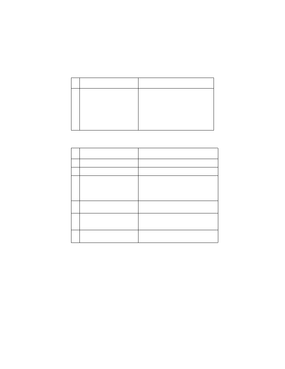
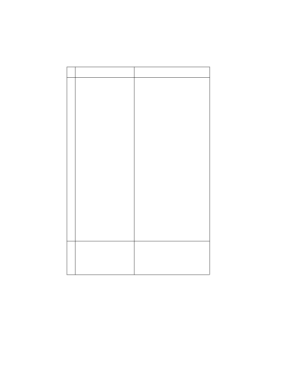
Symptom Table
Symptom
Action
Printer Code 1,4
Replace the printer board EPROM;
if necessary replace the printer board.
Printer Code 1,6
Go to
“Transport Service Check” on page
Printer Code 1,8
Replace the printer board EPROM;
if necessary replace the printer board.
Printer Code 1,10
Go to
Printer Code 1,12
Replace the printer board EPROM;
if necessary replace the printer board.
Printer Code 1,14
Go to
Printer Code 3,4
Go to
“Transport Service Check” on page
Printer Code 3,8
Go to
“Transport Service Check” on page
Printer Code 9,2
Replace the printer board EPROM;
if necessary replace the printer board.
Printer Code 9,4
Go to
“Transport Service Check” on page
Power Problem
No LEDs or LCD pixels light up
during POR, no machine activ-
ity:
Go to
“Power Service Check” on page 11
Maintenance Station Problem
Maintenance station does not
move, or fails to clean or cap the
printhead:
Go to
Carrier Transport Problem
No carrier movement, slow car-
rier movement, carrier stops:
Go to
“Transport Service Check” on page
Operator Panel Problem
Incorrect or no lit LEDs or LCD
display, or buttons do not work
properly:
Go to

Diagnostic Information
6
4012-0XX
Printer paper feed, misfeed, or
jam problem
Paper fails to stop at first print
line:
Envelopes fail to feed:
Paper misfeeds, multifeeds,
jams, picks but fails to feed, or
fails to exit:
Paper skews:
Go to
“First Print Line Service Check” on
.
Go to
“Envelope Feed Service Check” on
.
Go to
“Printer Paper Feed Service Check”
Go to
“Printer Paper Path Service Check”
Scanner paper feed, misfeed, or
jam problem
Go to
“Scanner Document Feed Service
.
Printing Problem
Test prints, faxes, or printer jobs
do not print correctly (not a print
quality problem).
Go to
“Printing Problem Service Check” on
Print Quality Problem
Test prints, faxes, and printer
jobs print but output has voids or
uneven density or is fuzzy,
smudged, or faint.
Go to
“Print Quality Service Check” on
Scanning Problem
No scanned image or incorrect
scanned image:
Go to
“Scanner Service Check” on page
Communications Problem
Cannot send fax, cannot receive
fax, or cannot connect with
remote machine:
Go to
“Communications Service Check”
.
Symptom
Action

4012-0XX
7
Service Checks
Communications Service Check
FRU
Action
1
Fax or LCU Card
Cannot make telephone con-
nection to other fax machine.
No dialtone
Verify correct dialing method (tone or
pulse).
TEL and LINE connections reversed.
Verify phone number and availability of
other fax machine.
Turn Call Monitoring on and listen to the
speaker during dial. You should hear the
ring and a 0.5 second 1000Hz calling tone
from your machine, a 1 second pause,
then the 3 second 2100Hz fax response
tone and a 1650Hz-1850Hz “warbling”
handshaking tone from the called
machine.
Check the connections of LCU card J2 to
fax card J11. If the problem still exists,
replace the LCU board, and then if neces-
sary, the fax board.
2
Cannot receive faxes.
Machine not set for auto-answer.
TEL and LINE connections reversed.
A telephone on the same line is already
off-hook.
Machine connected to the wrong tele-
phone line.
Damaged telephone line to machine.
Check memory; faxes received during
paper jams are stored and printed after
jam is cleared.
Make sure “Receive into memory” is set to
No.
If handshaking between fax machines can
be established, the LCU board should be
OK. If necessary, replace the fax board.
Diagnostic Information
8
4012-0XX
Envelope Feed Service Check
First Print Line Service Check
FRU
Action
1
Envelope Loading
Be sure the envelope guides have been
turned to the envelope load positions.
Be sure the envelope guides are against
the envelopes.
Go to and perform the
.
FRU
Action
1
Printer End-of-Forms Flag
Check the flag for binds or damage.
2
Printer End-of-Forms Sensor
Check the sensor for dirt.
3
Printer Board
Check the End-of-Forms sensor, measure
the voltage at pin 2 of U28 on the printer
board. The voltage should change from 0 to
5 V dc as you block and unblock the End-of-
Forms sensor S1.
4
Feed Arm Assembly
Check all parts of the feed arm assembly for
binds, wear, or damage.
5
Software Setting
Use Toolkit, one of the setup programs
installed on the PC, to adjust the Top of Form
setting.
6
Operator Panel
Go to

4012-0XX
9
Maintenance Station Service Check
The maintenance station has two functions:
1. Cleans the printhead nozzles during the print operation.
2. Seals the printhead when it is not being used to prevent the noz-
zles from drying.
Note: If the failure remains, replace the printer board.
FRU
Action
1
Maintenance Drive Assembly
Warning: Disconnecting the maintenance
motor while the machine is plugged in can
damage the printer board. Voltage is present
on the board even with the power switch off.
Disconnect J4 from the printer board. Check
for 18 ohms (±4 ohms) between pins 1 and 2
at the motor. If the reading is incorrect,
replace the maintenance drive assembly.
Check for motor pins shorted to the motor
housing. If you find a shorted pin, replace the
maintenance drive assembly. If the symptom
remains, replace the printer board.
A bind in the drive assembly can prevent the
motor from turning. Check for binds and
loose or worn parts in the drive assembly.
Also check the motor gear.
2
Printer Board
Turn the machine off and disconnect J4 from
the printer board. Turn the machine on and
check for a pulse of 15 V dc between J4-1
and ground on the system board as the
printer goes through POST.
3
Maintenance Rocker Asm
Check for binds or wear.
4
Wiper
A worn wiper causes degraded print quality
just after a maintenance cleaning. Check for
loose or worn wiper.
5
Cap
A worn cap causes the printhead nozzles to
dry and clog. Check for loose or worn cap.

Diagnostic Information
10
4012-0XX
Operator Panel Service Check
FRU
Action
1
Power Supply
Disconnect J2 from the fax board and
check the following voltages on the power
supply cable:
J2-1 to GND = +5 V dc
J2-3 to GND = +34 V dc
If you do not have correct voltage, replace
the power supply. Be sure to unplug the
machine before you reconnect the power
supply to the fax board.
2
Operator Panel Board
Operator Panel Cable
Perform the Operator Panel Test; see
“Operator Panel Test” on page 24
If some of the buttons do not work, check
the contacts on the back of the keypads
and the surface of the lands on the opera-
tor panel board. Replace the keypads as
necessary. Check the continuity of the
operator panel cable before replacing the
operator panel board.
3
Fax Board
Turn the printer on. Check for +5 V dc at
J4-3 on the fax board.

4012-0XX
11
Power Service Check
The operator panel power key does not control line power. With the
machine turned off the power supply is still active and there is volt-
age to both the fax and printer boards. To remove power you must
unplug the machine.
FRU
Action
1
Power Supply
Disconnect J2 from the fax board, J11
from the printer board and check the fol-
lowing voltages on both power supply
cables:
Pin-1 to GND = +5 V dc
Pin-3 to GND = +34 V dc
If you do not have correct voltage, replace
the power supply. Be sure to unplug the
machine before you reconnect the power
supply to the boards.
2
Printhead Cable
Parallel Cable
Unplug the machine. Disconnect one of
the listed components and plug in the
machine. Look for a symptom change.
Check the failing part for shorts and
replace as necessary. Repeat this proce-
dure for the remaining listed parts.
3
Printer Board
Disconnect the fax board from the printer
board. Run the Print Engine Test. If the
test does not run and there are no
mechanical problems, replace the printer
board.
4
Fax Board
Check for +5 V dc at the fax board J9-4,
and check for +34 V dc at J9-2. If the volt-
ages are incorrect replace the fax board.

Diagnostic Information
12
4012-0XX
Printer Paper Feed Service Check
If your machine does not have paper jam problems, go on to the ser-
vice check. If your machine does have a paper jam problem, exam-
ine it for the following before you begin the service check.
•
Check the entire paper path for obstructions.
•
Make sure there is not too much paper in the Automatic Sheet
Feed (150 sheets or less depending on the thickness).
•
Make sure the correct type of paper is in the machine.
•
Check for static in the paper.
•
Make sure the rear of the carrier guide is on top of the paper
guide.
FRU
Action
1
Printer Board
With J5 disconnected and power on,
check for +24 V dc between J5-3 and
ground, and between J5-4 and ground on
the printer board. If the voltage is not
present, check for motor pins shorted to
the motor housing. If you find a shorted
pin, replace the motor. If you still have a
failure after replacing the motor, replace
the printer board.
4012-0XX
13
2
Paper Feed Motor
A noisy or chattering motor or a motor that
fails to turn, can be caused by:
• An open or short in the motor
• An open or short in the motor driver on
the printer board
• A bind in the paper feed mechanism
Warning: Disconnecting the paper feed
motor while the machine is plugged in can
damage the printer board. Voltage is
present on the board even with the power
switch off.
Check for 100 ohms (±20 ohms) between
the following pins on the motor:
Pin 1 to Pin 4
Pin 2 to Pin 4
Pin 3 to Pin 5
Pin 3 to Pin 6.
If the readings are incorrect, replace the
motor. Check for motor pins shorted to the
motor housing. If you find a shorted pin,
replace the motor. If the failure remains,
replace the printer board.
Although the paper feeds in a forward
direction only, the paper feed motor turns
in two directions. If the paper feed motor
turns in one direction only, replace the
printer board.
Binds in the paper feed motor or gear train
can cause intermittent false paper jam
errors. Remove the paper feed motor and
check the shaft for binds. Also check for
loose or worn motor gears.
3
Gears
Check for binds in the gear train and paper
feed mechanism. To do this, rotate the
largest gear by hand. If you notice a bind,
isolate it by removing the small idler gear
on the outside of the right side plate and
rotate the gears again. Replace any worn
or binding gears, rollers, or bearings.
FRU
Action

Diagnostic Information
14
4012-0XX
4
Feed Arm Assembly
At the beginning of the paper feed opera-
tion, the paper feed motor reverses
momentarily to allow the feed arm pawl to
drop off the home position notch in the
ASF side plate. If the pawl fails to drop off
the notch, check the feed arm assembly
for binds, and worn or broken parts.
5
Auto Sheet Feed (ASF)
Check the following for wear or damage:
• Pick Rollers
• Envelope Bucklers
• All parts inside the left and right edge
guides.
6
End-of-Forms Flag
Check for binds or damage.
7
Star Rollers
Check for worn or binding rollers. Check
for broken star roller springs.
8
Ejectors
After the paper exits from the exit rollers,
the paper feed motor reverses causing the
feed arm pawl to restore to the home posi-
tion in the ASF side plate. At the same
time, the paper ejectors move the last
sheet of paper into the exit tray. If the ejec-
tors do not move or restore, check them
for worn, loose, or broken parts; also
check for interference with the front cover.
FRU
Action
4012-0XX
15
Printer Paper Path Service Check
Examine the machine for the following before you begin this service
check:
•
Check the entire paper path for obstructions.
•
Be sure the paper guides are not worn or broken and are posi-
tioned against the paper without binding or buckling the paper.
•
Be sure the correct type of paper is in the machine.
•
Be sure the rear of the carrier guide is on top of the paper guide.
FRU
Action
1
Large and Small Feed Rollers
Check for wear and binds.
2
Large Feed Roller Springs
Check for damage.
3
Auto Sheet Feed (ASF)
Check for equal pressure between the left
and right pick rolls and their pads; this can
be caused by the paper load shaft gears
being misaligned by one tooth in the ASF
frame.
Check the following for wear or damage:
• Envelope Bucklers
• All parts inside the left and right edge
guides.
4
End-of-Forms Flag
Check for binds or damage.
5
Exit Roller
Check for wear or binds.
6
Star Rollers
Check for wear or binds. Check for broken
star roller springs.
7
Ejectors
Check the front cover; if it is installed
incorrectly it can interfere with the ejectors.
Make sure the front bottom cover is
installed correctly. If the front bottom cover
is not installed correctly, the ejectors can
hang on the cover possibly causing severe
paper jams.
After the paper exits from the exit rollers,
the paper feed motor reverses causing the
feed arm pawl to restore to the home posi-
tion in the ASF side plate. At the same
time, the paper ejectors move the last
sheet of paper into the exit tray. If the ejec-
tors do not restore, check them for worn,
loose, or broken parts.
Diagnostic Information
16
4012-0XX
Print Quality Service Check
FRU
Action
1
Print Cartridge
Be sure the machine has a known good
print cartridge.
2
Printhead Carrier Assembly
Reseat the printhead cables in the printer
board and check the following parts for
wear or damage:
• Print Cartridge Latch
• Latch Spring
• Carrier
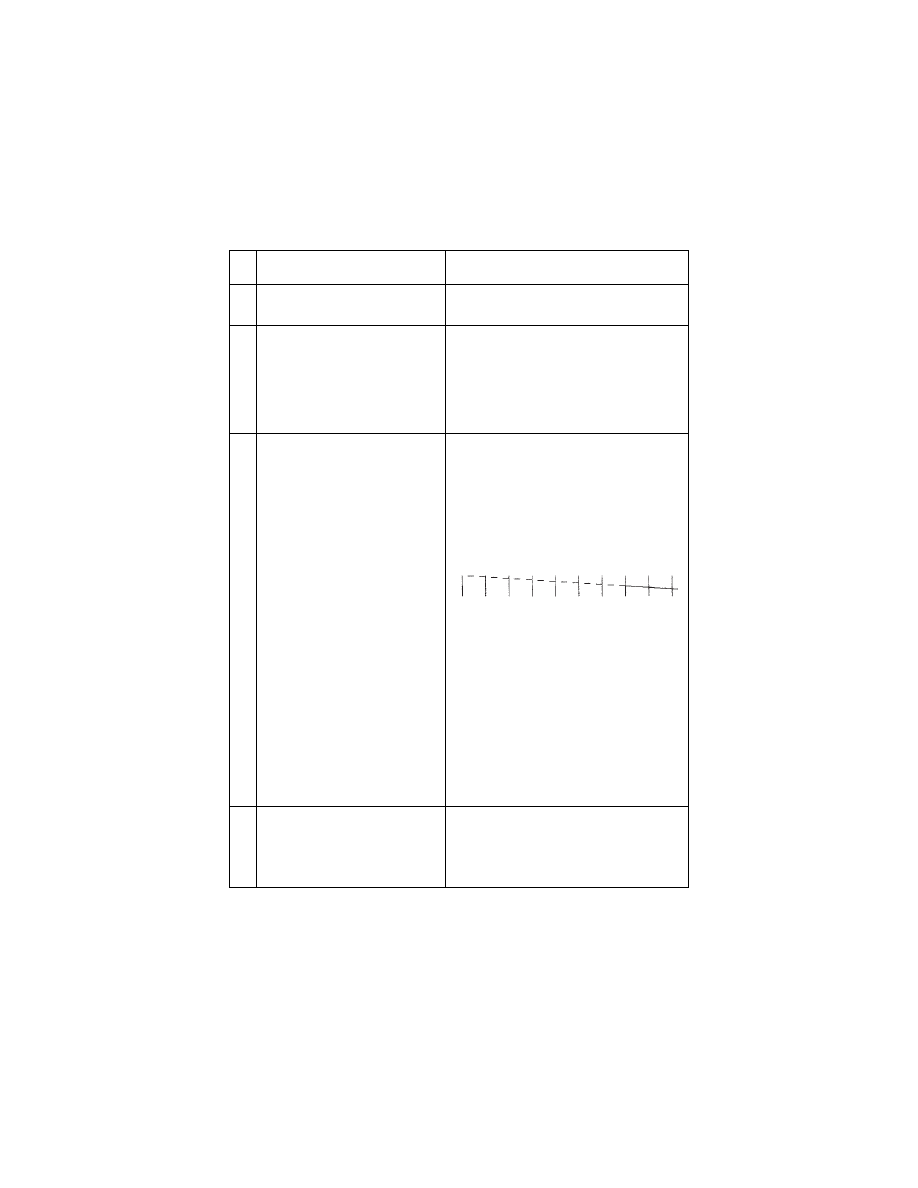
3
Printer Board
Printhead Cable
Rubber Backer
Perform the
. Look
for a break in the diagonal line at the bot-
tom of the test pattern. A broken line indi-
cates one or more print nozzles are
clogged. Run the test again to verify the
failure. If there are even breaks in the diag-
onal line similar to the pattern shown
below, replace the printer board.
If there is a single break or random breaks
in the diagonal line check the following:
Check the gold-plated contacts on the end
of the cable that connects to the carrier for
dirt and wear. Use only a clean dry cloth to
clean the contacts. Also check the cable
for damage. You may need to remove the
cable from the carrier to inspect it.
A worn rubber backer will result in poor
contact between the printhead cable and
the print cartridge. Check the rubber
backer for wear.
4
Maintenance Station
Intermittent nozzle failures can be caused
by worn parts in the maintenance station.
Go to and perform the
, then return
to this check.

4012-0XX
17
5
Paper Feed
Ink smudging and smearing can be
caused by paper problems or problems in
the paper feed area. Check the following:
• Correct type of paper is in the machine.
Also check the paper for curl and wrin-
kles.
• Feed roller for wear, dirt, or looseness.
• Gears for wear or binds.
• Paper path for obstructions.
• Star rollers for binds or dirt.
The exit roller and star rollers keep ten-
sion on the paper by moving slightly
faster than the feed rollers. A binding
star roller can put vertical marks on the
paper.
• Subframe is properly snapped into posi-
tion.
6
Transport
Blurred print and voids can be caused by
problems in the transport area. Check the
following:
• Transport belt for wear.
• Carrier guide and carrier guide rod for
wear or dirt.
• Idler pulley parts for wear, damage, or
looseness.
• Encoder strip for wear or dirt.
• Subframe is properly snapped into posi-
tion.
7
Bidirectional Alignment
Uneven vertical lines can be adjusted by
performing the
FRU
Action

Diagnostic Information
18
4012-0XX
Printing Problem Service Check
If test prints, faxes, or printer jobs do not print correctly (not a print
quality problem), run the Print Engine Test.
FRU
Action
1
Machine does not start the test:
Make sure all the pins of connector J7 are
shorted together and try to run the test
again.
If the test still does not start, go to
.
2
The machine responds but does
not complete the test:
Refer to the appropriate service check for
the symptom.
3
The tests prints correctly:
There is a problem with the print job, the
parallel cable, the LCU board, the fax
board, the fax/LCU cables, or the printer/
fax cable. Check the cables and their con-
tinuity. If no problem is found, replace the
fax board and then the LCU board.

4012-0XX
19
Scanner Document Feed Service Check
Before beginning service, examine the following:
•
Are the pages damaged or dog-eared, are pages stuck together?
•
Is the paper being fed too thin (less than 16 lb paper), or too thick
(greater than 24 lb paper)?
•
Are the pages too small to feed properly?
•
Too many pages being fed (greater than 20)?
•
Are the scanner entry guides set properly?
•
Are both sides of the scanner front frame latched?
The scanner document feeder can be checked using the
FRU
Action
1
Feed Rollers & Restraint Pad
Check for dirty, worn, or damaged rollers.
Make sure the restraint pad and its spring
are in good condition. Make sure the pick
springs and all roller springs are undam-
aged. Refer to
2
Paper Sensors
The operator panel message should
change when a document is fed into the
scanner. Check for fax board J6-3 to
change from 0 V dc to +5 V dc as the entry
sensor flag is toggled. Check for fax board
J6-6 to change from 0 V dc to +5 V dc as
the second sensor flag is toggled.
3
Motor
Fax board J3-5 and J3-6 should have
+15 V dc.
Warning: Disconnecting scanner motor
while the machine is plugged in can dam-
age the fax board. Voltage is present on
the board even with the power switch off.
Unplug the machine before proceeding.
Disconnect the motor from the fax board.
Motor pins 1 through 4 should not have
continuity to each other or to ground.
4
Gear Train
Inspect the gear teeth for damage. Rotate
the gear train to check for binds.
5
Fax Board or Connections
Check scanner motor (J3) and paper sen-
sor (J6) cable connections to fax board.

Diagnostic Information
20
4012-0XX
Scanner Service Check
FRU
Action
1
LED Array
A failed LED array results in either black or
very dark output. If a single LED fails, the
output will have a black or dark vertical
fuzzy stripe. The voltage at fax board J7-3
should be +12 V dc during a scan.
Replace the array if the voltage is correct.
2
Scanner and Fax Board
If there is no image (all white image),
check the connection of the scanner data
cable to both the scanner (J1) and the fax
board (J8). A scanner CCD unit failure
results in either a white image, a black
image, or an image with one or more thin
vertical black lines. Replace the scanner
CCD unit.
It is not possible to be certain whether an
all-black or all-white scan failure is due to
the CCD unit or the fax board. In general,
if the machine performs non-scanning
functions involving the fax board (for
example, receiving a fax, exchanging
stored data with the PC, or accepting data
entered from the operator panel) the fax
board is probably OK. If replacing the CCD
unit does not correct the problem, reinstall
the old CCD unit and replace the fax
board.
3
PC Scanner Software
If the machine sends faxes properly but
does not create a scanned image file on
the PC, there is a problem with the PC
scanner software installation or configura-
tion.
4012-0XX
21
Transport Service Check
FRU
Action
1
Transport Motor
Check the motor for binds, or loose motor
pulley.
Warning: Disconnecting the transport
motor while the machine is plugged in can
damage the printer board. Voltage is
present on the board even with the power
switch off. Unplug the machine before pro-
ceeding.
Disconnect the transport motor (J6) from
the printer board. Check for 8 to 18 ohms
between pins 1 and 2 on the motor cable.
If the reading is incorrect, replace the
motor.
Check for motor pins shorted to the motor
housing. If you find a pin shorted to the
housing, replace the motor. If the failure
remains, replace the printer board.
2
Printer Board
Unplug the machine and disconnect J6
from the printer board. Plug the machine
in and check for a pulse of 3 to 5 V dc
between J6-1 and ground and between
J6-2 and ground on the printer board as
the machine goes through POST.
3
Transport Belt
Carrier Guide or Guide Rod
Idler Pulley Parts
Cable Clip
Check for worn, loose or broken parts.
Clean the carrier guide rod. Do not lubri-
cate the rod or the carrier rod bearings.
Check for obstructions blocking carrier
movement.
4
Encoder Strip
Check for wear and dirt.
5
Printhead Cables
Be sure the printer board connectors J1
and J2 are fully seated. Check the cables
for damage.
6
Maintenance Station
A problem with the maintenance station
can cause carrier movement problems at
the right margin:
Go to the

Diagnostic Aids
22
4012-0XX
Diagnostic Aids
3
Call Monitoring
Call Monitoring plays tones during the call connection. This is helpful
in diagnosing communication problems.
To invoke this aid, press Setup, then select SPK. Press an arrow key
to turn the speaker on or off, press OK to save the setting and then
press Stop.
Error Report
When a fax transmission cannot be completed, the machine prints
an Error Report. This is useful in determining whether service is
required to correct the communication problem.
Frame Service Position
For ease of access to the electronic boards, the frame can be piv-
oted out of the way without being removed. Remove the covers. Dis-
connect the cables from the frame on the right side of the printer and
fax boards. Unsnap the right front and right rear frame supports from
the machine base. Pivot the printer frame up 90 ° on the left feet.
Hex Print Mode
Perform this test with a black print cartridge installed. Use hex mode
to help evaluate data stream problems. All data (including both con-
trol and character data) print in hexadecimal digits instead of ASCII.
To activate, press Setup, then select PRT. Use the right arrow to
move the cursor to Diag and press OK. Select HEX. Then send the
PC job to be printed in hexadecimal.
Press Stop to return to ASCII mode, and press Stop again to exit
from the service menus.

4012-0XX
23
Machine Checkout
Use the standard functions of the machine to verify the correct oper-
ation of its subsystems. Copying a document confirms that the scan-
ner and the printer engine is working. Sending a fax verifies that the
scanner and the telephone connection are OK. Printing a job from
the PC verifies that the parallel port and the print engine are OK.
Receiving a fax to memory confirms that the telephone connection
and the memory on the fax board are good.
Memory Test
Use the Memory Test for testing both system memory and document
memory.
1. Press Setup.
2. Press 2104 to enter the Service Functions menu.
3. Press the right arrow key to select Testing, then press OK.
4. Select MEM.
5. Press Stop several times to exit the test.
Operator Panel Service Position
To operate the machine with the covers removed, the operator panel
can be positioned on a table at the left of the machine and the cable
connected to the fax board.

Diagnostic Aids
24
4012-0XX
Operator Panel Test
This test activates each LED in sequence and cycles all pels of the
LCD display. It also allows the servicer to test each button.
1. Press Setup.
2. Press 2104 to activate the Service Functions menu.
3. Press the right arrow to move the pointer to Testing, then press
OK.
4. Select PNL.
5. Press any button (except Stop) to start the button test. Follow the
instructions on the display to press and test each button.
6. Press Stop at any time to end the test. Press Stop several times
to exit the menus.
Reset Button
This recessed button on the operator panel is covered with a shield
and must be pressed with a small tool or straightened paper clip.
The Reset button does a hardware reset of the fax board and opera-
tor panel. Pressing Reset does not erase stored faxes or the con-
tents of the phone book. The Reset button does not reset the printer
board; unplugging the machine resets the printer board.
Print Engine Test
Use the Print Engine test for testing the printer board and inkjet
printer engine independent of the other machine subsystems. This
test can be run with the fax, LCU, or operator panel boards discon-
nected or defective.
1. Unplug the machine.
2. Remove the right cover and locate printer board header J7.
3. Short all four pins together with a screwdriver and plug the
machine in.
The test print will run continuously until the machine is unplugged.
The pins do not need to stay shorted after the test starts.

4012-0XX
25
Purge Test
This test prints out a nozzle test pattern followed by several gray
lines and another nozzle test pattern. Use this test to check the func-
tion of all the nozzles in the print cartridge. This test also checks the
electronic connection to the print cartridge. During the test, the print-
head cartridge goes through a maintenance cleaning at the mainte-
nance station. Run this test with either the black or the color
cartridge installed.
1. Press Setup.
2. Select PRT.
3. Select PUR.
4. Press Stop several times to exit the menus.
Scanner Feed Test
This test exercises the scanner Automatic Document Feed to allow
you to verify the paper pick and scanner motor function. This test
feeds paper but does not test scanning.
1. Press Setup.
2. Press 2104 to activate the Service Functions menu.
3. Use the right arrow to select Testing and press OK.
4. Select ADF.
5. Insert one or more sheets into the scanner ADF and follow the
panel instructions.
6. Press Stop several times to exit the service menus.

Diagnostic Aids
26
4012-0XX
Setting the Machine Serial Number
When the fax board is replaced, the machine serial number needs to
be saved into memory.
1. Press Setup.
2. Press 2104 to activate the Service Functions menu.
3. Press OK to enter the Service Setup menu.
4. Select SRN.
5. Enter the machine serial number (4012 followed by 10 charac-
ters) found on the rear label.
6. Press OK to save the number. Press Stop several times to exit
the service menus.
Test Print
From the operator panel, print the Setup Conditions report (press
Setup, then press the button for LST) to determine that the operator
panel, the fax board, the printer board, the ASF, and the print engine
are performing correctly.
There are two other test prints available. Press Setup, then the but-
ton for PRT. Press the right arrow to select Diag and then press OK.
On this menu, FON prints the fonts available in the printer. TST
prints a test print which can show a non-functioning printhead noz-
zle. Press Stop several times to exit the service menus.

Repair Information
27
4012-0XX
Repair Information
7
This chapter explains how to make adjustments to the printer and
how to remove defective parts. Read
before handling elec-
tronic parts.
Warning: Medley has a soft power key which does not remove
machine power; it shuts down visible machine activity. When the
machine is plugged in power is always present on the fax board and
printer board. Before connecting or disconnecting any machine com-
ponents always unplug the machine from the wall outlet.

Repair Information
28
4012-0XX
Handling ESD-Sensitive Parts
Many electronic products use parts that are known to be sensitive to
electrostatic discharge (ESD). To prevent damage to ESD-sensitive
parts, follow the instructions below in addition to all the usual pre-
cautions, such as turning off power before removing logic boards:
•
Keep the ESD-sensitive part in its original shipping container (a
special “ESD bag”) until you are ready to install the part into the
machine.
•
Make the least-possible movements with your body to prevent an
increase of static electricity from clothing fibers, carpets, and fur-
niture.
•
Put the ESD wrist strap on your wrist. Connect the wrist band to
the system ground point. This discharges any static electricity in
your body to the machine.
•
Hold the ESD-sensitive part by its edge connector shroud
(cover); do not touch its pins. If you are removing a pluggable
module, use the correct tool.
•
Do not place the ESD-sensitive part on the machine cover or on
a metal table; if you need to put down the ESD-sensitive part for
any reason, first put it into its special bag.
•
Machine covers and metal tables are electrical grounds. They
increase the risk of damage because they make a discharge path
from your body through the ESD-sensitive part. (Large metal
objects can be discharge paths without being grounded.)
•
Prevent ESD-sensitive parts from being accidentally touched by
other personnel. Install machine covers when you are not work-
ing on the machine, and do not put unprotected ESD-sensitive
parts on a table.
•
If possible, keep all ESD-sensitive parts in a grounded metal cab-
inet (case).
•
Be extra careful in working with ESD-sensitive parts when cold-
weather heating is used because low humidity increases static
electricity.

4012-0XX
29
Adjustments
Bidirectional Alignment Adjustment
Perform this adjustment with the black print cartridge installed.
Note: For machines at software version 5.15.5.2 or lower (press
Setup LST to print the report listing the version number), this adjust-
ment affects only Letter quality mode and Step 5 and its note do not
apply. If bidirectional alignment in Draft mode is a problem on a
machine at this level, enter Setup PRT Setup and either set Printing
Quality to Letter or set Printing Direction to Unidir.
1. Press Setup.
2. Select PRT, select Diag (diagnostics), and then select Bidi.
3. Open the top cover to see the alignment test print. A page loads
and the bidirectional alignment pattern prints. The pattern con-
sists of three lines of vertical bars. The bars are aligned when
the adjustment is correct. The following sample requires the cen-
ter vertical bars to be moved to the right.
4. The center bars can be aligned in increments of 1/1200
(0.02 mm). If the lines are not straight, press the left arrow key
(
←
) to move the center of the lines to the left, or press the right
arrow key (
→
) to move them to the right. Each time you press an
arrow key the three lines print.
5. When the alignment is correct, press the top right key under the
display to switch to Draft mode. Follow the same procedures as
above to align the bars in Draft mode.
Note: Single left and right arrows are printed while in Letter
mode, and triple left and right arrows are printed while in Draft
mode.
6. When the adjustment is complete press Stop to save the setting
then press Stop again to exit the Setup menu.
Repair Information
30
4012-0XX
Removal Procedures
The following procedures are arranged according to the name of the
part discussed. When there is artwork to support a procedure, it fol-
lows the text.
Note: Unplug the machine before beginning any electrical service.
The power key does not remove power from the electronics.
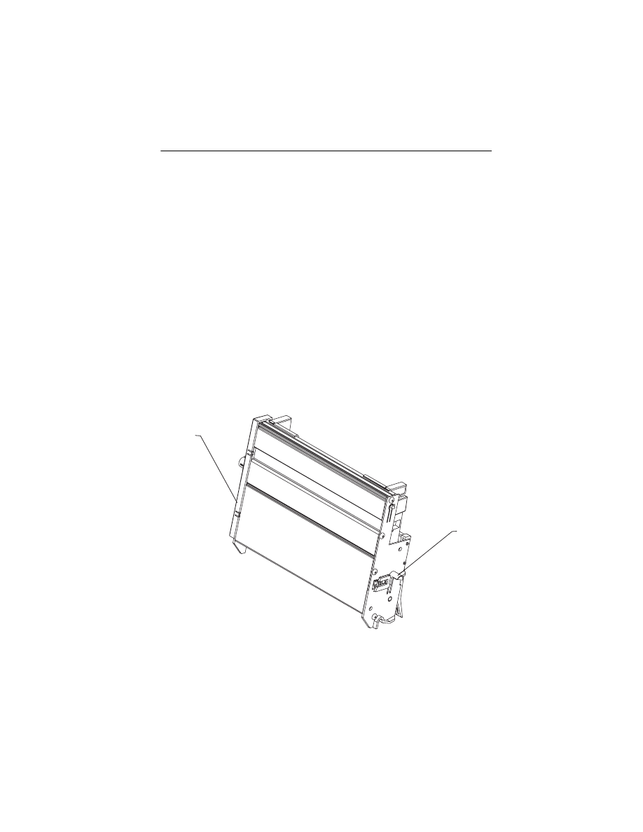
Auto Sheet Feed (ASF) Assembly Removal
1. Remove the paper load lever.
2. Remove the left and right side covers.
3. Remove the clip from the right side subframe, if installed.
4. Remove the top cover.
5. Release the latches holding the subframe to the ASF.
6. Push in the two latches [A] that secure the ASF to the side
frame, then lift up the sheet feed to remove it from the machine.
When you reinstall the ASF, be sure the feed arm assembly is verti-
cal, with the feed pawl at the top.
A
A

4012-0XX
31
ASF Envelope Buckler and Pick Roller Hub Removal
1. Remove the ASF assembly.
2. Remove the inside C-clip from the pick roller shaft and pull the
shaft to the right far enough to remove the envelope bucklers
and pick rollers.
3. Remove the pick roller hubs from the bucklers.
ASF Right and Left Edge Guide Assemblies Removal
1. Remove the ASF assembly.
2. Remove the manual insert tray by prying one of the side frames
away from it.
3. Remove the inside C-clip from the pick roller shaft and pull the
shaft out to the right.
4. Remove the pick roller and buckler assemblies.
5. Remove the paper load lever and shaft by pulling them out from
the right side of the ASF assembly. Be careful not to lose the
small gear on the left end of the shaft. When you reinstall this
shaft, it must be parallel with the ASF housing.
6. Pivot the guide assembly up and pry it off the back plate.
Battery Option
1. Unplug the machine.
2. Open the access door on the left side cover. The battery option
is attached to the door.
3. Disconnect the battery option cable from the fax board.
4. Remove the battery board mounting screw.
Note: If the battery option is being replaced, install the jumper on
the new battery option board. If the battery option is being removed,
install the jumper at J9 (2 center pins) of the fax board. Failure to
install the jumper will cause a dead machine condition.
Carrier Guide Rod Removal
1. Open the top cover.
2. Remove the print cartridge.
3. With the carrier centered, carefully release the two carrier guide
rod latches and lift the shaft slightly.
4. Unlatch the two carrier guide rod latches by pushing the latches
to the rear.
5. Gently push the carrier to the extreme right and remove the car-
rier guide rod.

Repair Information
32
4012-0XX
Carrier Removal
1. Open the top cover.
2. Remove the right side cover
3. Remove the print cartridge.
4. Disconnect the printhead cables from the printer board.
5. Cut the cable tie and remove the toroid.
6. Move the carrier in line with the opening in the carrier transport
motor frame.
7. Reach through the opening and pull the belt from the carrier.
8. To unlock the carrier guide rod latches, rotate the rod top-to-rear.
Gently push the carrier guide rod latches, at each end of the rod,
to the rear and lift up the rod until the sensor on the carrier clears
the encoder strip. Move the rod to the left until the right end can
be lifted above the frame. Remove the carrier guide rod to the
right, above the carrier motor. Be careful not to damage the
encoder strip.
9. Pull the ends of the printhead cables into the machine, then
remove the cables from the four retainers in the paper guide
starting from the right.
Carrier Transport Belt Removal
1. Open the top cover and then remove the left and right side
covers.
2. Move the carrier in line with the opening in the carrier transport
motor frame.
3. Reach through the opening and pull the belt from the carrier.
4. Remove the belt from the carrier transport motor pulley.
5. Remove the belt from the idler pulley and pull it through the
opening in the left side frame.
Note: When you reinstall the belt be sure to insert the bottom of the
belt into both the lower and upper belt grips on the carrier. DO NOT
INSERT THE TOP OF THE BELT INTO THE UPPER GRIP
.

4012-0XX
33
Carrier Transport Motor Removal
1. Open the top cover and then remove the left and right side
covers, then the lower front cover.
2. Disconnect the carrier transport motor (J6) from the printer
board.
3. Remove the two motor mounting screws and remove the motor.
Carrier Transport Motor Frame Removal
1. Remove the top cover and then the left and right side covers.
2. Remove the rear and front covers.
3. Disconnect J6 from the printer board.
4. Disconnect the four scanner connectors and the speaker con-
nector from the fax board.
5. Remove the scanner and subframe.
6. Move the carrier in line with the opening in the carrier transport
motor frame.
7. Reach through the opening and pull the belt from the carrier.
8. To unlock the carrier guide rod latches, rotate the rod top-to-rear.
Gently push the carrier guide rod latches, at each end of the rod,
to the rear and lift up the rod until the sensor on the carrier clears
the encoder strip. Remove the carrier guide rod through the
opening in the left side frame. Be careful not to damage the
encoder strip.
9. A latch on the top front end of each side frame holds the trans-
port motor frame in place. Push up the latches on the front of the
side frames and pivot the carrier transport motor frame down
and out of the side frames.

Repair Information
34
4012-0XX
Covers Removal
Front Cover
1. Remove the left and right side covers.
2. Flex the front cover to release the latches on each end.
3. Lift the cover to free the lower latch and remove the cover.
Note: When reinstalling the front cover, make sure the lower latch
and side latches are installed properly to prevent the cover from
interfering with the paper ejectors.
Rear Cover
1. Remove the left and right side covers.
2. Flex the tabs on the subframe to release both latches.
3. Lift the cover to free the lower latch and remove the cover.
Top Cover
1. Bend the subframe slightly to free the top cover pivot pin.
2. Remove the top cover.
Right Side Cover
1. Remove the paper load lever.
2. Open the operator panel cover and the top cover.
3. Remove the screw from inside the subframe just above scanner.
4. Lift on the top inner edge of the cover to free the top latches.
5. Rotate the cover to the right to free the lower latches.
Left Side Cover
1. Open the operator panel cover and the top cover.
2. Remove the screw from inside the subframe just above scanner.
3. Lift the top inner edge of cover to free the top latches.
4. Rotate the cover to the left to free the lower latches.
5. If the battery option is installed, disconnect its cable from the fax
board (J9).
Operator Panel and Cover
1. Remove the left and right side covers.
2. Flex the subframe to free one of the pivot pins.
3. Remove the two screws and the ESD shield.
4. Disconnect the operator panel cable from the back of the opera-
tor panel.
5. Unsnap the operator panel from the cover.

4012-0XX
35
Encoder Strip Removal
The encoder strip can be easily damaged; use care when removing
or installing.
1. Open the top cover.
2. Move the carrier in line with the opening on the carrier transport
motor frame.
3. Reach through the opening and pull the belt from the carrier.
4. To unlock the carrier guide rod latches, rotate the rod top to rear.
Gently push the carrier guide rod latches at each end of the rod
to the rear and lift up the rod until the sensor on the carrier clears
the encoder strip. Place the carrier on top of the paper guide.
5. Remove the encoder strip from the left mounting peg. To do this,
push the right latch slightly to the left.
6. Remove the encoder strip from the right latch.
When you install the encoder strip, be sure it is fully seated on the
left mounting peg.
End-of-Forms Flag Removal
1. Remove the covers.
2. Disconnect the printer board connectors: J1, J2, J4, J5, and J6.
3. Disconnect the fax board connectors: J3 and J8.
4. Raise the machine frame into the service position.
5. Pivot the weighted end of the end-of-forms flag through the
opening in the middle frame.
6. Unsnap the flag by moving it to the rear.
Exit Roller Assembly Removal
1. Remove the covers.
2. Remove the carrier transport frame.
3. Pivot the paper ejector pusher toward the front then pull it to
remove the paper ejector from the shaft.
4. Remove the bushing from the left end of the exit shaft. To do this,
pull the tab and rotate the bushing.
5. Slide the exit roller to the left and lift it out of the machine.

Repair Information
36
4012-0XX
EPROM Removal
1. Unplug the machine before beginning any electrical service. The
power key does not remove power from the electronics.
2. Remove the top cover.
3. Disconnect the printhead cables from the printer board.
4. Disconnect connectors J4, J5, and J6 from the printer board.
5. Disconnect the scanner motor connector J3 from the fax board.
6. Release the latches at the right-front and right-rear legs of the
frame, then lift and pivot the frame 90 ° to the left into the service
position.
7. Gently pry the EPROM from the board.
8. To install the EPROM:
a. Ensure the orientation notch is to the right for the fax board or
to the front for the printer board. Refer to:
.
b. Ensure that each module pin aligns with each socket, so
there are no bent pins.
c. Apply even pressure on the top of the module until it is seated
against the socket.

4012-0XX
37
Fax Board, Printer Board, and LCU Board Removal
1. Unplug the machine before beginning any electrical service. The
power key does not remove power from the electronics.
2. Remove the left and right side covers, the front cover and the
rear cover, and disconnect J1, J2, J4, J5 and J6 from the printer
board.
3. Disconnect the scanner motor cable from J3 and scanner data
cable J8 from the fax board.
4. Unsnap the two print engine feet at the right side of the machine.
5. Pivot the print engine up around the left pivots, being sure no
cables are being strained, until the left side of the print engine is
resting on the table.
6. Disconnect the remainder of the cables required to remove the
board.
7. Cut the cable tie around the support posts.
8. Remove the EPROM (see
) for
installation on the new board. Remove the ground screw and
remove the board.
Note: If the printer board is replaced, check the bidirectional align-
ment. If the fax board is replaced, inspect the LCU board for physical
damage. Replace the LCU board if damage is present. The machine
serial number needs to be saved into memory, if the fax board is
replaced. Refer to
“Setting the Machine Serial Number” on page 26
Feed Arm Assembly Removal
1. Remove the covers.
2. Remove the ASF.
3. Remove the C-clip from the center of the large gear and remove
the feed arm assembly.
Inside Idler Gears Removal
1. Remove the covers.
2. Remove the ASF.
3. Disconnect the printhead cables from the printer board.
4. Remove the paper guide.
5. Remove the C-clip from the feed arm assembly and remove the
feed arm assembly.
6. Pull the idler gears off the mounting studs.

Repair Information
38
4012-0XX
Large Feed Roller Assembly Removal
1. Remove the top cover.
2. Disconnect the printhead cables from the system board.
3. Disconnect connectors J4, J5, and J6 from the system board.
4. Disconnect scanner motor connector J3 from the fax board.
5. Release the latches at the right front and right rear legs of the
frame, then lift and pivot the frame 90 ° to the left into the service
position.
6. Disconnect the 3 springs from the bottom of the middle frame
assembly.
7. Remove the large feed roller assembly.
Left Side Frame Removal
1. Remove the covers.
2. Remove the print cartridge.
3. Remove the subframe.
4. Remove the ASF.
5. Disconnect the printhead cables from the printer board.
6. Disconnect connectors J4, J5, and J6 from the printer board.
7. Remove the machine from the base. To do this, release the
latches at the right-front and right-rear legs of the frame, then lift
and pivot the frame 90 ° to the left. Lift the frame to disengage
the left legs from the base.
8. Move the carrier in line with the opening in the carrier transport
motor frame.
9. Reach through the opening and pull the belt from the carrier.
10. To unlock the carrier guide rod latches, rotate the rod top-to-rear.
Gently push the carrier guide rod latches, at each end of the rod,
to the rear and lift up the rod until the sensor on the carrier clears
the encoder strip. Remove the carrier guide rod through the
opening in the left side frame. Be careful not to damage the
encoder strip.
11. Pull the ends of the printhead cables into the machine, then
remove the cables from the four retainers in the paper guide
starting from the right.
12. Disengage the left paper guide latch by carefully moving the rear
of the left side frame to the left.
13. Disengage the right side of the paper guide from the latch and lift
it from the machine.

4012-0XX
39
14. A latch on the top front end of each side frame holds the trans-
port motor frame in place. Push up the latches on the front of the
side frames, then pivot the carrier transport motor frame down
and out of the side frames.
15. Place the machine on its back and push the left side frame latch
to the rear and remove the frame from the machine.
16. Unsnap the feet from the left side frame.
When you reinstall the paper guide, be sure the front edge goes
under the rear of the carrier guide. If the paper guide is on top of the
carrier guide, push down the front, bottom edge. The paper guide
will snap under the carrier guide.
To install the left side frame onto the middle frame, align the right
side frame latch with the latching surface on the middle frame before
you align the roller shafts and carrier guide. It may be easier to do
this with the machine on its right side.
Maintenance Drive and Rocker Assemblies Removal
1. Remove the covers.
2. Remove the ASF.
3. Remove the right side frame.
4. Gently unlatch the maintenance assembly latches.
5. Slide out the maintenance drive assembly and then the rocker
assembly.
When you reassemble the drive assembly, be sure the forks engage
the pins on the rocker assembly.
Memory Option
1. Unplug the machine.
2. Open the access door in the left side cover.
3. Lift up the memory board to remove it.
Note: The 1MB option consists of two modules and the 3MB
option has six modules.
4. From the operator panel, print the Setup Conditions report
(press Setup, then select LST) to verify the installed memory is
recognized by the machine.

Repair Information
40
4012-0XX
Middle Frame Removal
1. Remove the covers.
2. Remove the print cartridge.
3. Remove the subframe.
4. Remove the ASF.
5. Disconnect the printhead cables from the printer board.
6. Disconnect J4, J5, and J6 from the printer board.
7. Remove the machine from the base. To do this, release the
latches at the right front and right rear legs of the frame, then lift
and pivot the frame 90 ° to the left. Lift the frame to disengage
the left legs from the base.
8. Remove the paper ejectors from the middle frame.
9. Remove the left side frame.
10. Remove the exit shaft.
11. Remove the small feed roller shaft.
12. Remove the large feed roller shaft and springs.
13. Remove the end-of-forms flag.
14. Remove the right side frame.
15. Remove the maintenance station.
Outside Idler Gears Removal
1. Remove the right cover.
2. Disconnect the printhead cables from the printer board.
3. Each gear is latched in place. Push up the latch and remove the
gear from the side frame stud by pulling the gear from the bot-
tom.
Paper Ejectors Removal
1. Remove the covers.
2. Pivot the paper ejector pusher toward the front then pull it to
remove the paper ejector from the shaft.
3. Unsnap the paper ejectors from the middle frame.
Paper Feed Motor Removal
1. Remove the right cover.
2. Disconnect the paper feed motor connector from printer
board J5.
3. Remove the two mounting screws.
4012-0XX
41
Paper Guide Removal
1. Remove the covers.
2. Remove the ASF.
3. Remove the subframe.
4. Disconnect the printhead cables from the printer board.
5. Pull the ends of the printhead cables into the machine, then
remove the cables from the four retainers in the paper guide
starting from the right.
6. Disengage the left paper guide latch by carefully moving the rear
of the left side frame to the left.
7. Disengage the right side of the paper guide from the latch and lift
it from the machine.
When you reinstall the paper guide, be sure the front edge goes
under the rear of the carrier guide. If the paper guide is on top of the
carrier guide, push down the front, bottom edge. It will snap under
the carrier guide.
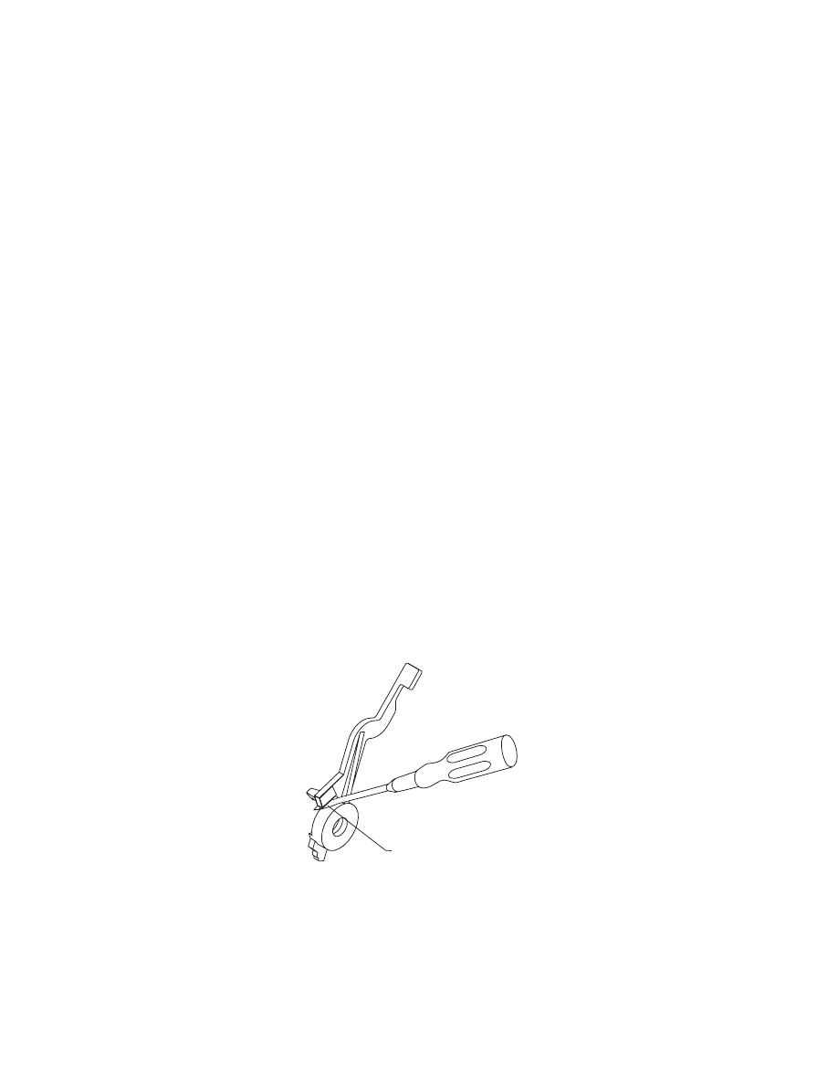
Paper Release Lever Removal
1. Remove the left cover.
2. Pull the paper release lever forward.
3. Place a screwdriver into the slot [A] of the paper release lever.
Push the screwdriver down to release the latch, then remove the
lever.
A

Repair Information
42
4012-0XX
Power Supply Removal
1. Unplug the machine before beginning any electrical service. The
power key does not remove power from the electronics.
2. Remove the left and right side covers.
3. Remove the front and rear covers.
4. Disconnect the scanner motor cable from J3 on the right side of
the fax board.
5. Disconnect the five cables connecting the printer board to the
print engine (J1, J2, J4, J5, J6).
6. Unsnap the two print engine feet at the right side of the machine.
7. Pivot the print engine up around the left pivots, being sure no
cables are being strained, until the left side of the print engine is
resting on the table.
8. Disconnect the power leads from the fax board (J2) and the
printer board (J11).
9. Remove the ground screw holding the power supply to the bot-
tom shield.
Note: Make sure the ground screw is secure when reinstalling
the power supply.
10. Unsnap the front latch and lift the power supply from the
machine. Make sure the power supply insulator remains in place
when reinstalling the power supply.
Print Engine Removal
1. Unplug the machine before beginning any electrical service. The
power key does not remove power from the electronics.
2. Remove the left and right side covers.
3. Remove the front and rear covers.
4. Disconnect the six cables connecting the fax board to the print
engine (J3, J4, J5, J6, J7, J8); cut the cable tie on the scanner
cable.
5. Disconnect the five cables connecting the printer board to the
print engine (J1, J2, J4, J5, J6).
6. Unsnap the two print engine feet at the right side of the machine.
7. Pivot the print engine up around the left pivots, being sure no
cables are being strained, until the left side of the print engine is
resting on the table.
8. Lift the print engine to free the left pivot feet from the bottom
cover.
4012-0XX
43
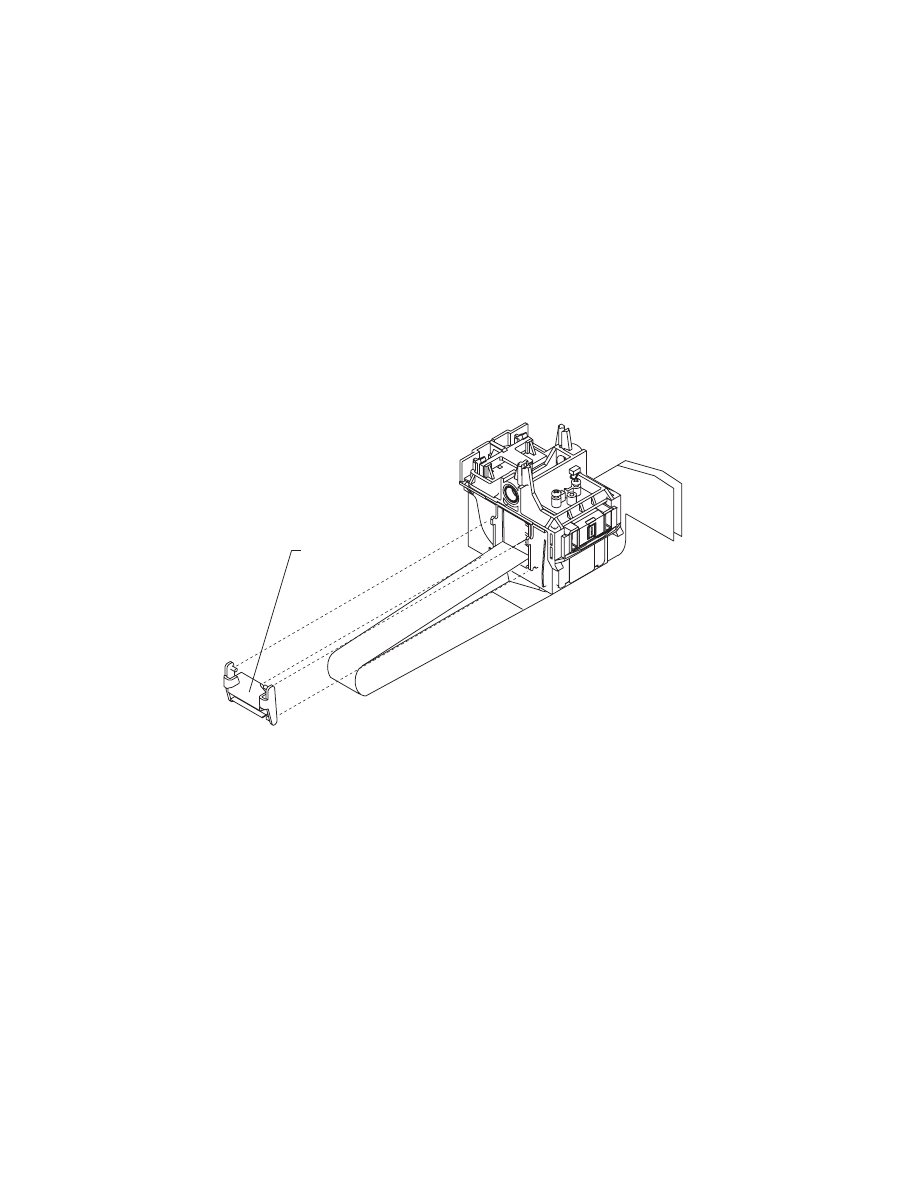
Printhead Cable Removal
1. Unplug the machine before beginning any electrical service. The
power key does not remove power from the electronics.
2. Open the top cover.
3. Remove the print cartridge.
4. Remove the carrier.
5. Remove the cable clip [A] from the left side of the carrier.
6. Remove the pointer from the front of the carrier.
7. Remove the two sensor mounting screws.
8. Push down the two latches that secure the cradle to the carrier
and pull the cradle up from the carrier.
9. Remove the printhead cable from the alignment pins.
The new cable comes without the folds in it. Place the new cable
next to the old cable and fold the new cable in the appropriate
places.
A

Repair Information
44
4012-0XX
Releasing Plastic Latches
Many of the parts are held in place with plastic latches. To remove
such parts, press the hook end of the latch away from the part to
which it is latched. The latches break easily. Release them carefully.
Never apply excessive force
when releasing the hook.
Hook

4012-0XX
45
Right Side Frame Removal
1. Remove the covers.
2. Remove the print cartridge.
3. Remove the subframe.
4. Remove the ASF.
5. Disconnect the printhead cables from the printer board.
6. Disconnect connectors J4, J5, and J6 from the system board.
7. Remove the machine from the base. To do this, release the
latches at the right front and right rear legs of the frame, then lift
and pivot the frame 90 ° to the left. Lift the frame to disengage
the left legs from the base.
8. Move the carrier in line with the opening in the carrier transport
motor frame.
9. Reach through the opening and pull the belt from the carrier.
10. To unlock the carrier guide rod latches, rotate the rod top-to-rear.
Gently push the carrier rod guide latches, at each end of the rod,
to the rear and lift up the rod until the sensor on the carrier clears
the encoder strip. Remove the carrier rod guide through the
opening in the left side frame. Be careful not to damage the
encoder strip.
11. Pull the ends of the printhead cables into the machine, then
remove the cables from the four retainers in the paper guide
starting from the right.
12. Disengage the left paper guide latch by carefully moving the rear
of the left side frame to the left.
13. Disengage the right side of the paper guide from the latch and lift
the guide from the machine.

Repair Information
46
4012-0XX
14. A latch on the top front end of each side frame holds the trans-
port motor frame in place. Push up the latches on the front of the
side frames, then pivot the carrier transport motor frame down
and out of the side frames.
15. Place the machine on its back, then unlatch the right frame latch
from the middle frame and remove the side frame.
Note: For reassembly you may want to remove the carrier guide
and reinstall it after you install the paper guide.
When you reinstall the paper guide, be sure the front edge goes
under the rear of the carrier guide. If the paper guide is on top of the
carrier guide, push down the front bottom edge. It will snap under the
carrier guide.
To install the right side frame onto the middle frame, align the right
side frame latch with the latching surface on the mid frame before
you align the roller shafts and carrier guide. It may be easier to do
this with the machine on its left side.

4012-0XX
47
Rubber Backer Removal
1. Open the top cover.
2. Remove the print cartridge.
3. Remove the printhead cable.
4. Remove the rubber backer from the carrier.
Small Feed Roller Assembly Removal
1. Remove the covers.
2. Remove the ASF.
3. Remove the paper guide.
4. Carefully remove the paper release lever.
5. Remove the bushing from the left end of the small feed roller
shaft. To do this, pull the tab and rotate the bushing.
6. Slide the small feed roller assembly to the left and lift it out of the
machine.
Star Roller Removal
1. Remove the covers.
2. Remove the subframe.
3. Move the carrier in line with the opening on the carrier transport
motor frame.
4. Reach through the opening and pull the belt from the carrier.
5. To unlock the carrier guide rod latches, rotate the rod top-to-rear.
Gently push the carrier guide rod latches at each end of the rod
to the rear and lift up the rod until the sensor on the carrier clears
the encoder strip. Place the carrier on top of the paper guide.
6. A latch on the top front end of each side frame holds the trans-
port motor frame in place. Push up the latches on the front of the
side frames and pivot the carrier transport motor frame down
and out of the side frames. Place the carrier transport motor
frame face down in front of the machine.
7. Remove the star roller by pushing it forward off the mounting peg
in the carrier transport motor frame.

Repair Information
48
4012-0XX
Scanner and Speaker Removal
1. Unplug the machine before beginning any electrical service. The
power key does not remove power from the electronics.
2. Remove the left and right side covers.
3. Remove the front cover.
4. Disconnect the scanner motor cable from J3 on the right side of
the fax board.
5. Disconnect the scanner paper sensor and LED/microswitch
cables from J6 and J7 on the left side of the fax board.
6. Cut the tie wrap and disconnect the scanner data cable J8 from
the left side of the fax board.
7. Unsnap the large tab holding the left end of the scanner to the
subframe.
8. Lift the scanner from the machine.
9. Disconnect the speaker from the fax board J5.
10. Slide the speaker toward the front to remove it.
Subframe Removal
1. Remove the left and right side covers.
2. Remove the rear cover.
3. Remove the top cover, the operator panel cover, and the front
cover.
4. Disconnect the four scanner cables (J3, J6, J7, J8) and the
speaker cable (J5) from the fax board.
5. Cut the cable tie.
6. Remove the clip from the right side.
7. Spread the tabs at the sides of the sheet feed to free the pins.
Warning: To avoid damage to the encoder strip, make sure the
carrier transport motor frame does not come unsnapped during
the next step.
8. Lift the tabs, rotating the subframe toward you to release the
subframe where it is snapped to the printer frame.
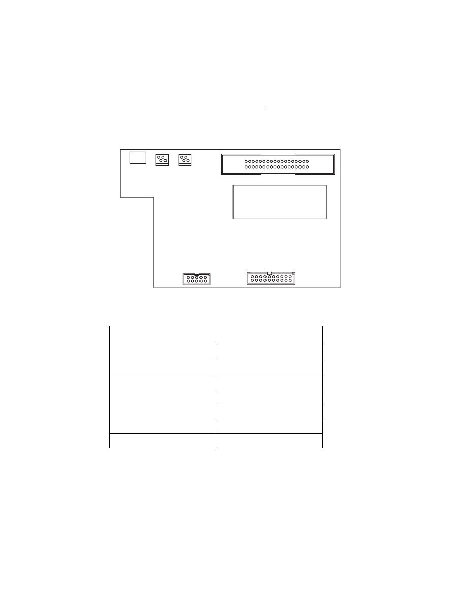
4012-0XX
49
Parts and Test Point Locations
9
LCU Board
LCU Board
Connector
Name
J1
Handset
J2
Phone Data to Fax Board
J3
Parallel Port
J4
Parallel Data to Fax Board
TJ1
Phone Line In
TJ2
External Phone
TJ2
TJ1
J3
J1
J2
J4
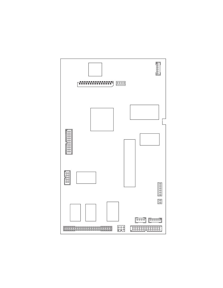
Parts and Test Point Locations
50
4012-0XX
Fax Board
J4
J5
J6
J7
J8
J9
J10
J11
J12
J1
J2
J3
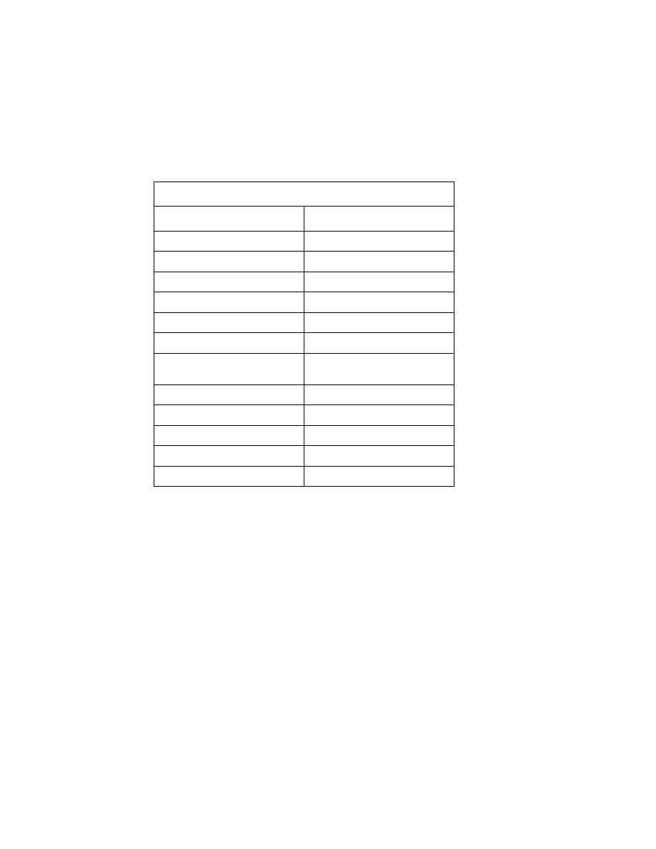
4012-0XX
51
Fax Board
Connector
Name
J1
Printer Board
J2
Power Supply
J3
Scanner Motor
J4
Operator Panel
J5
Speaker
J6
Scanner Paper Sensors
J7
LED Array & Scanner Closed
Switch
J8
Scanner Data
J9
Battery Backup Option
J10
Memory Option
J11
Phone Data from LCU Board
J12
Parallel Data from LCU Board
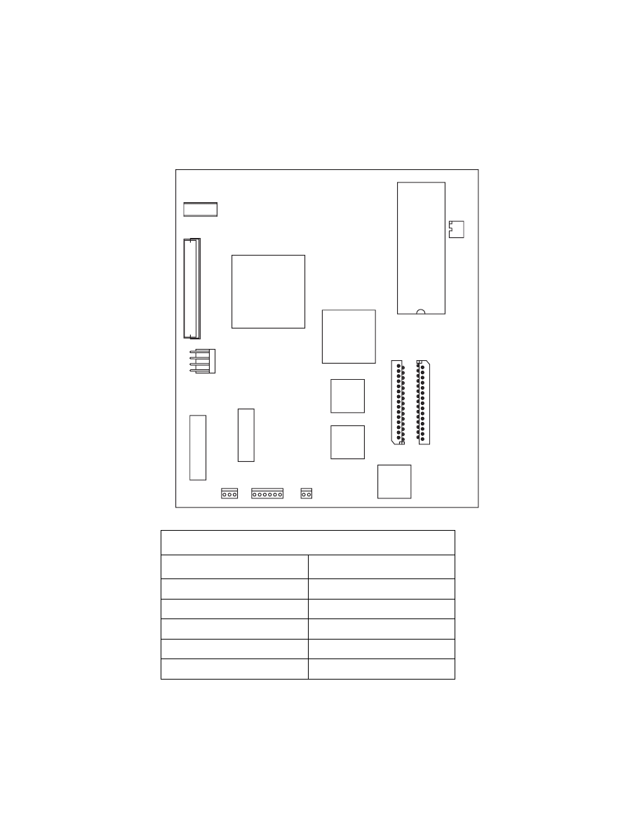
Parts and Test Point Locations
52
4012-0XX
Printer Board
Printer Board
Connector
Name
J1
Printhead
J2
Printhead
J3
Not Used
J4
Maintenance Motor
J5
Paper Feed Motor
J4
J5
J6
J7
EPROM
S1
J9
J11
J1
J2
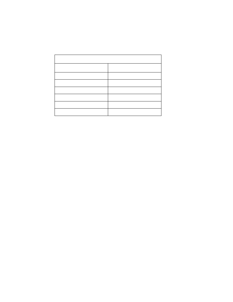
4012-0XX
53
J6
Carrier Motor
J7
POR Test Jumper
J8
Not Used
J9/J9A
Fax Board
J10
Not Used
J11
Power Supply
Printer Board
Connector
Name

Preventive Maintenance
54
4012-0XX
Preventive Maintenance
10
Following these recommendations can help prevent problems and
maintain optimum performance.
Lubrication Specifications
Lubricate only when parts are replaced or as needed, not on a
scheduled basis.
Warning: Petroleum-based greases can attack polycarbonate parts
causing premature failure. Use only mineral oil-based grease.
Use a mineral oil-based grease to lubricate the following:
•
All gear mounting studs
•
Right end of the exit roller at the right side frame
•
Right end of the small feed roller at the right side frame
•
Left end of the large feed roller at the left side frame
•
Both ends of the ASF pick roll shaft at the ASF side frames
•
Transport belt idler pulley hole
•
Inside surface of the transport idler pulley tension wedge where it
touches the left side frame.
Do not lubricate the carrier guide rod or carrier guide rod bearings.

4012-0XX
55
Scanner Cleaning Procedure
The scanner restraint pad and paper feed rollers should be cleaned
when necessary to avoid feed problems.
1. Clean the pad with isopropyl alcohol, wiping downward in the
paper movement direction.
2. Clean the three paper feed rollers using isopropyl alcohol.
Turn the gear train with your thumb to clean the entire surface of
the rollers.
3. Wipe paper dust, ink, or foreign material off the scanner white
reference strip inside the front frame with a clean cloth. If neces-
sary, use isopropyl alcohol.
The scanner lenses and mirrors do not normally require clean-
ing; the microcode compensates for dust on the optical surfaces.
If, however, these surfaces become unusually dirty or the
scanned image becomes fuzzy, remove the scanner and clean
the mirrors and lenses with isopropyl alcohol.
Caution: Do not hold the scanner by the mirrors or supports. If
the supports are bent it can change alignment in the scanner.
Hold the scanner by the plastic.
Note: Do not disassemble any optical components of the scan-
ner.

56
4012-0XX
Parts Catalog
4
How To Use This Parts Catalog
•
SIMILAR ASSEMBLIES: If two assemblies contain a majority of
identical parts, they are broken down on the same list. Common
parts are shown by one index number. Parts peculiar to one or
the other of the assemblies are listed separately and identified by
description.
•
AR: (As Required) in the Units column indicates that the quantity
is not the same for all machines.
•
NS: (Not Shown) in the Asm-Index column indicates that the part
is procurable but is not pictured in the illustration.
•
PP: Parts Packet
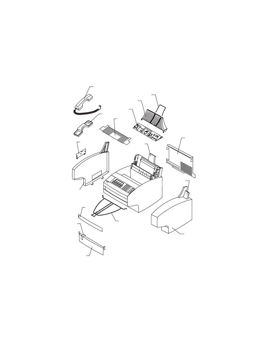
4012-0XX
57
Assembly 1: Covers
9
19
1
20
21
3
6
4
10
5
15
8
2
11
22
7
58
4012-0XX
Description
4012-005 P/N
4012-006
4012-009 P/N
1
Top Cover Asm w/guides
69G6828
69G6828
2
Front Cover
69G6875
69G6875
3
Rear Cover
69G6874
69G6874
4
Right Side Cover
69G6869
69G6869
NS
Screw, Right Side Cover
PP 69G6846
5
Memory/Battery Access Door
69G6899
69G6899
6
Paper Load Lever
69G6888
69G6888
7
Left Side Cover
69G6870
69G6893
NS
Screw, Left Side Cover
PP 69G6846
8
Bezel, front
69G6861
69G6861
9
Handset w/Cable
N/A
69G6822
10
Cradle, Handset
N/A
69G6894
NS
Screw, Cradle Mounting
PP 69G6846
11
Left output Guide
1367493
1367493
15
Extender, Input Tray, Printer
69G6890
69G6890
19
Panel, Scan Input Tray
69G6889
69G6889
20
Tray, Scan Input
69G6891
69G6891
21
Extender, Scan Input Tray
69G6871
69G6871
22
Tray, Scanner Output
69G6830
69G6830
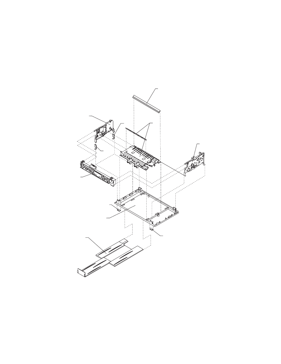
4012-0XX
59
Assembly 2: Frame
2
9
10
3
4
1
8
8
6
5
7
60
4012-0XX
Description
4012-005 P/N
4012-006
4012-009 P/N
1
Base Asm
69G6900
69G6900
2
Left Side Frame
1367209
1367209
3
MIddle Frame Asm
1367219
1367219
4
Right Side Frame
1367229
1367229
5
Carrier Transport Motor Frame
1367309
1367309
6
Exit Tray Asm
69G6824
69G6824
7
Carrier Guide
1367079
1367079
8
Foot
69G6860
69G6860
9
Leg, left Rear
69G6882
69G6882
10
Leg, left Front
69G6883
69G6883
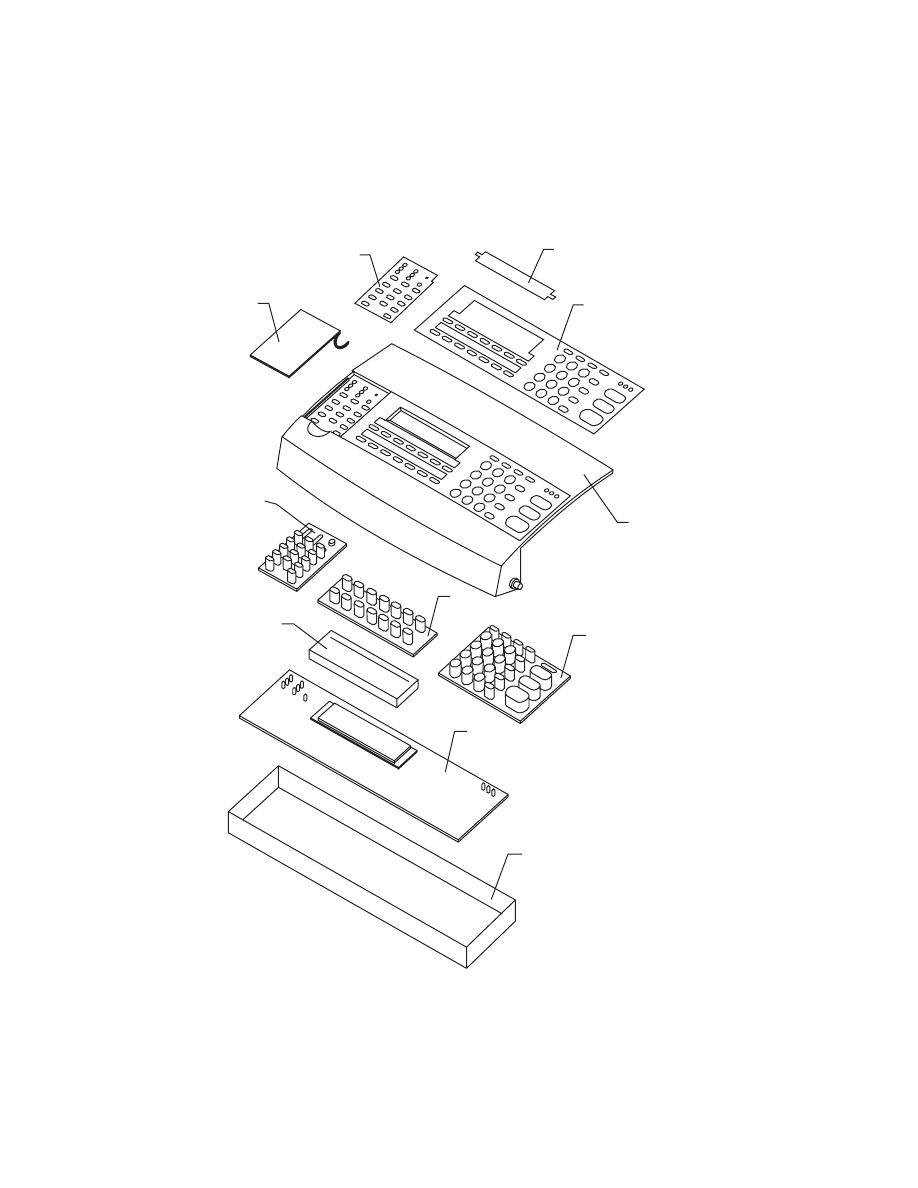
4012-0XX
61
Assembly 3: Operator Panel
9
3
10
2
1
6
5
4
8
7
11
62
4012-0XX
Description
4012-005 P/N
4012-006
4012-009 P/N
1
Operator Panel Cover
69G6901
69G6902
1
Operator Panel Cover 4012-009
69G6905
2
Overlay, Operator Panel
69G6885
69G6886
3
Overlay, Sm Operator Panel
69G6897
69G6898
NS
Shield, Reset Button
PP 69G6846
4
Keypad, Left
69G6896
69G6896
5
Keypad, Center
69G6895
69G6895
6
Keypad, Right
69G6884
69G6884
7
Operator Panel Board
69G6806
69G6806
8
Lens, Display
69G6831
69G6831
9
Door, Button
69G6887
69G6887
10
Shield, Directory
PP 69G6846
NS
Cable, Operator Panel Cable
to Fax Board
69G6878
69G6878
11
Shield, EMC
69G6903
69G6903
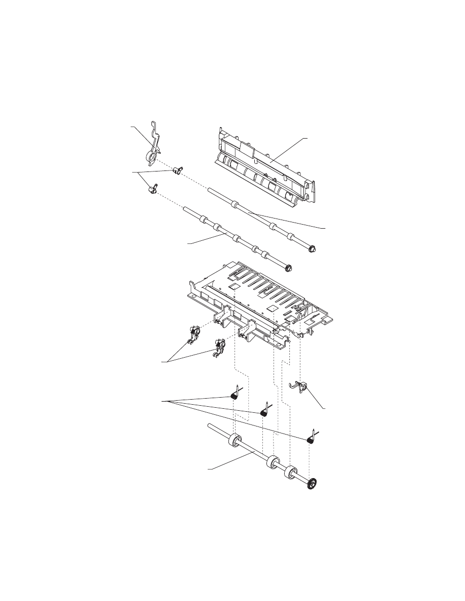
4012-0XX
63
Assembly 4: Printer Paper Feed Assembly
4
6
7
9
8
1
2
3
5
64
4012-0XX
Description
4012-005 P/N
4012-006
4012-009 P/N
1
Paper Release Lever
1367179
1367179
2
Bushing, PP 1367169
3
Paper Guide
1367339
1367339
4
Small Feed Roller Asm
1367279
1367279
5
Exit Roller Asm
1367289
1367289
6
Ejector B/M
1367266
1367266
7
Spring, PP 1367169
8
End-of-Form Flag
1367049
1367049
9
Large Feed Roller Asm
1367269
1367269
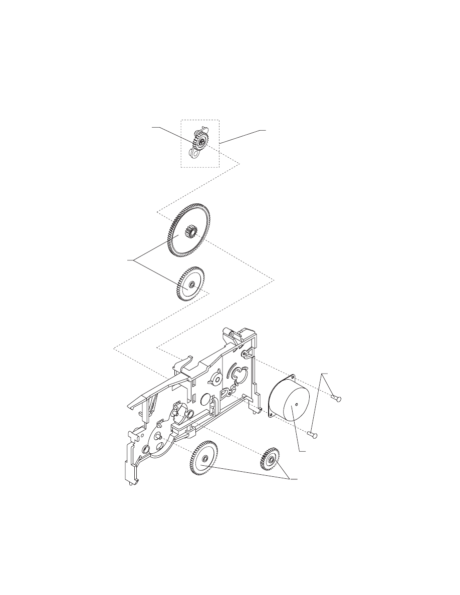
4012-0XX
65
Assembly 4: Printer Paper Feed Assembly (cont.)
11
13
12
11
10
14

66
4012-0XX
Description
4012-005 P/N
4012-006
4012-009 P/N
10
Paper Feed Motor
1367239
1367239
NS
Toroid, Paper Feed Motor
1374338
1374338
11
Gears B/M
1367249
1367249
12
Feed Arm Asm
1367259
1367259
13
C-Clip, PP 1367169
14
Screw, PP 1367169
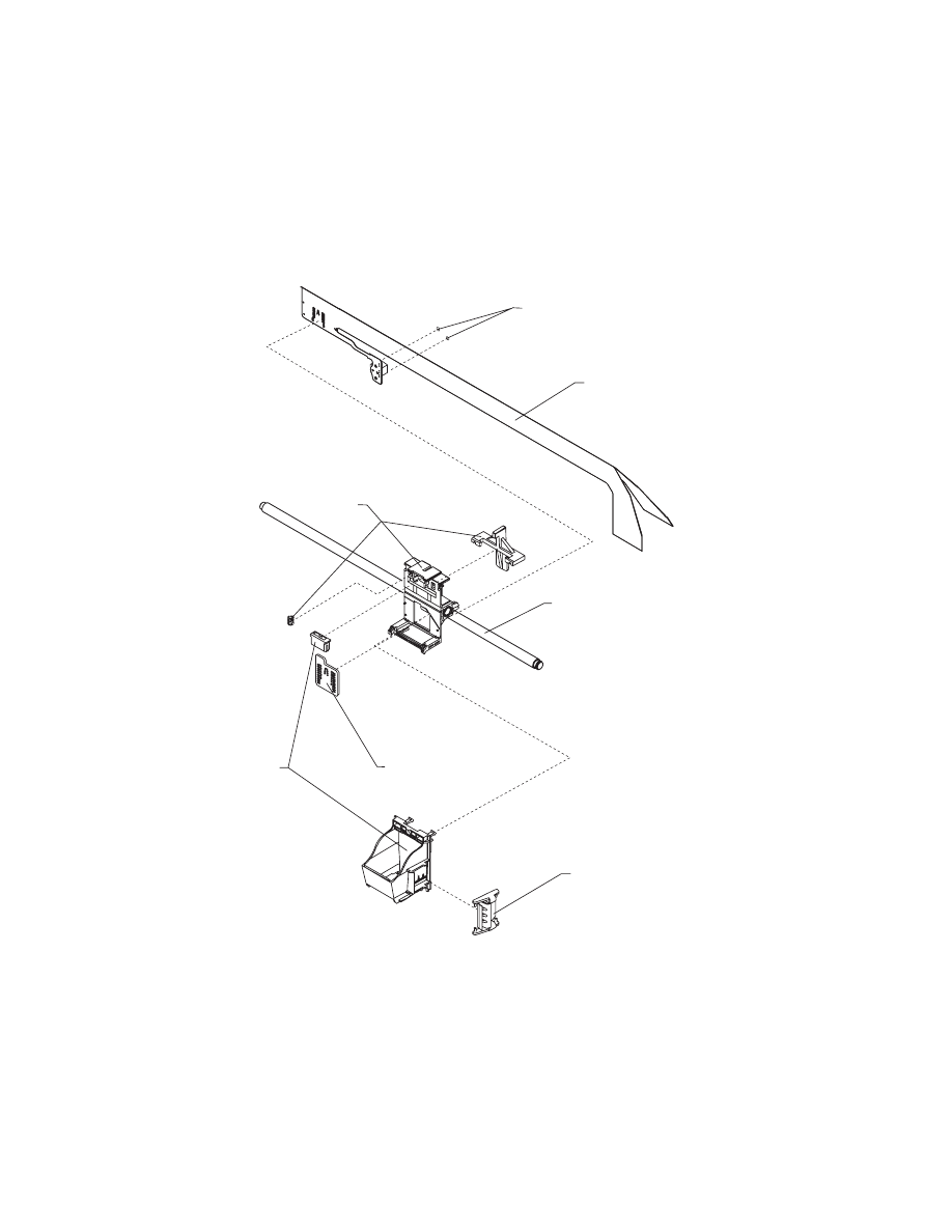
4012-0XX
67
Assembly 5: Carrier
3
1
4
6
1
2
5

68
4012-0XX
Description
4012-005 P/N
4012-006
4012-009 P/N
1
Carrier Asm
1367299
1367299
2
Printhead Cable
1367149
1367149
NS
Toroid, Printhead Cable
1374338
1374338
3
Screw, PP 1367169
4
Rubber Backer
1367109
1367109
5
Carrier Guide Rod
1367089
1367089
6
Clip, PP 1367169
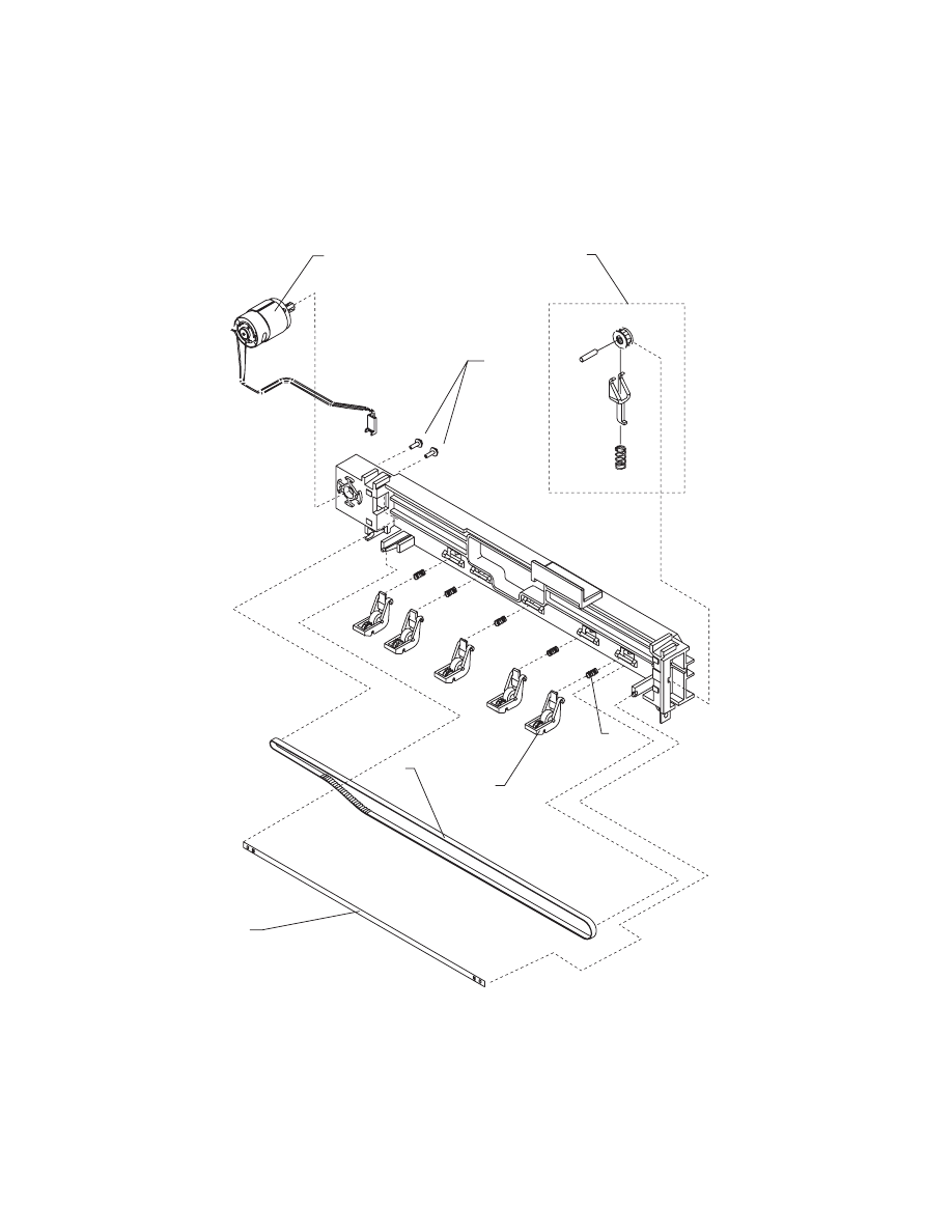
4012-0XX
69
Assembly 6: Carrier Transport
1
2
4
5
3
6
7

70
4012-0XX
Description
4012-005 P/N
4012-006
4012-009 P/N
1
Carrier Motor
1367319
1367319
2
Screw, PP 1367169
3
Carrier Belt
1367359
1367359
4
Encoder Strip
1367379
1367379
5
Star Roller Asm
1425705
1425705
6
Spring PP 1367169
7
Idler Pulley B/M
1367329
1367329
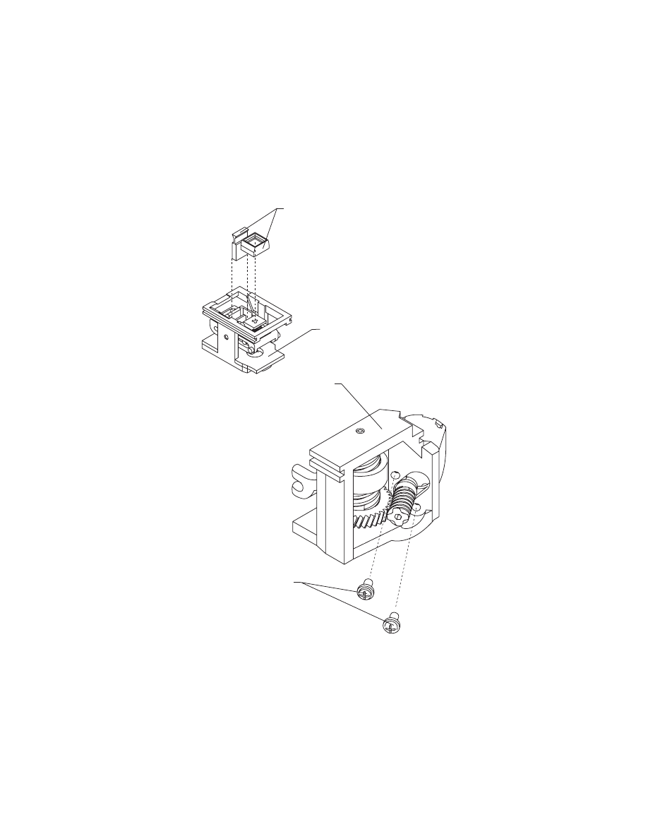
4012-0XX
71
Assembly 7: Maintenance Station
3
1
4
2
72
4012-0XX
Description
4012-005 P/N
4012-006
4012-009 P/N
1
Maintenance Station
Rocker Asm
1425669
1425669
2
Maintenance Station Drive Asm
1367399
1367399
3
Wiper & Cap B/M
1367389
1367389
4
Screw PP 1367169
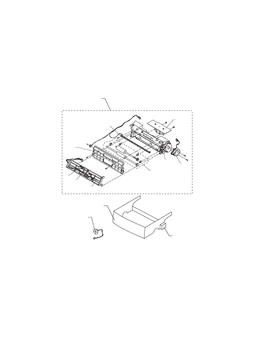
4012-0XX
73
Assembly 8: Scanner
3
6
9
10
7
1
4
2
8
5
14
12
13
74
4012-0XX
Description
4012-005 P/N
4012-006
4012-009 P/N
1
Scanner, Complete
69G6836
69G6836
2
CCD Asm.
69G6857
69G6857
3
Front Frame Asm
69G6843
69G6843
4
Feed Roller Kit
69G6840
69G6840
5
Gear Kit (3 Gears)
69G6844
69G6844
6
Pad Unit
69G6845
69G6845
7
LED/Frame Switch Asm.
69G6841
69G6841
8
Motor Assembly
69G6842
69G6842
9
L/P Sensor
69G6839
69G6839
NS
Screws, PP 69G6846
10
Paper Path Cover
69G6855
69G6855
12
Subframe, Scanner
69G6833
69G6833
13
Cap & Bracket Asm
69G6835
69G6835
14
Speaker
69G6838
69G6838
NS
Jumper, Front Frame ESD Gnd.
69G6862
69G6862
NS
Shield, Scanner
69G6863
69G6863
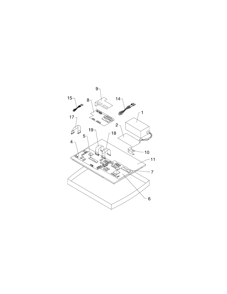
4012-0XX
75
Assembly 9: Electronics
76
4012-0XX
Description
4012-005 P/N
4012-006
4012-009 P/N
1
Power Supply
69G6805
69G6805
2
PS Insulator
69G6879
69G6879
NS
Screw, PS Mounting
1624852
1624852
4
Fax Card, W/O EPROM
69G6800
69G6800
5
EPROM, Fax Card
69G6810
69G6810
6
Printer Card, W/O EPROM
69G6802
69G6802
7
EPROM, Printer Card
1375418
1375418
8
LCU Card w/Bezel
69G6808
69G6801
9
Shield, LCU Card
69G6880
69G6880
10
Shield, Printer
69G6881
69G6881
11
Shield Asm, Bottom
69G6837
69G6837
14
Line Cord, U.S.
69G6868
69G6868
15
Cable, Telephone
69G6892
69G6892
NS
Toroid, Printer/Fax Cable
69G6906
69G6906
16
Cable, Printer to Fax
69G6872
69G6872
17
Cable, Scanner to Fax
69G6873
69G6873
18
Cable, Fax to LCU Digital
69G6876
69G6876
19
Cable, Fax to LCU Analog
69G6877
69G6877
NS
Jumper, Fax Card J9
PP 69G6846
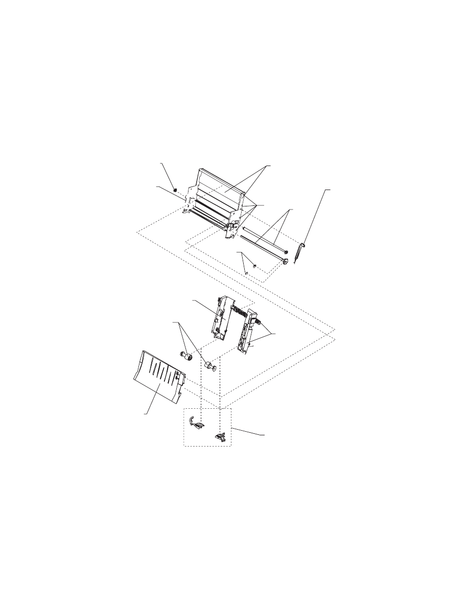
4012-0XX
77
Assembly 10: Automatic Sheet Feed (ASF)
10
4
2
7
6
11
1
8
7
9
3
5

78
4012-0XX
Description
4012-005 P/N
4012-006
4012-009P/N
1
R. Edge Guide & Strip
1425574
1425574
2
L. Edge Guide Asm
1425578
1425578
3
Pick Roll & Paper Load B/M
1367469
1367469
4
Pick Roll Hub Asm
1367463
1367463
5
Paper Load Arm
1425580
1425580
6
Envelope Buckler B/M
1367019
1367019
7
Side & Back Plate B/M
1425582
1425582
8
Gears, B/M
1367249
1367249
9
E-Ring, PP 1367169
10
Screw, PP 1367169
11
Manual Insert Tray, Printer
1425585
1425585

4012-0XX
79
Assembly 11: Options
Description
4012-005 P/N
4012-006
4012-009 P/N
1
Memory Option, 1MB
(2 modules)
69G6803
69G6803
2
Memory Option, 3MB
(6 modules)
69G6804
69G6804
3
Battery Option
69G6807
69G6807
NS
Screw, Battery
Mounting
PP 69G6846
4
Demo code ROM,
4012-011,4012-012
69G6811
69G6811

80
4012-0XX
Index
A
Abbreviations
Adjustments
ASF Envelope Buckler And Pick
Roller Hub Removal
ASF Right And Left Edge Guide
Assemblies Removal
Auto Sheet Feed Removal
B
Battery Option
Bidirectional Alignment
Adjustment
C
Call Monitoring
Carrier Belt Removal
Carrier Guide Removal
Carrier Removal
Carrier Transport Motor Frame
Removal
Carrier Transport Motor
Removal
CCD
Communications Service Check
Covers Removal
D
Diagnostic Aids
Diagnostic Information
E
Encoder Strip Removal
End-of-Forms Flag Removal
Envelope Feed Service Check
EPROM Removal
Error Report
Exit Roller Assembly Removal
F
Fax Board, Printer Board, and
LCU Board
Feed Arm Assembly Removal
First Print Line Service Check
Frame Service Position
G
General Information
H
Handling ESD-Sensitive Parts
Hex Print Mode
How To Use This Parts Catalog
I
Inside Idler Gears Removal
L
Large Feed Roller Assembly
Removal
Left Side Frame Removal
Lubrication Specifications
M
Machine Checkout
Maintenance Approach
Maintenance Drive And Rocker
Assemblies Removal
Maintenance Station Service
Check
Memory Option
Memory Test

81
4012-0XX
Middle Frame Removal
O
Operator Panel Service Check
Operator Panel Service Position
Operator Panel Test
Options
Outside Idler Gears Removal
P
Paper Ejectors Removal
Paper Feed Motor Removal
Paper Feed Service Check
Paper Guide Removal
Paper Path Service Check
Paper Release Lever Removal
Parts and Test Point Locations
Parts Catalog
Power Service Check
Power Supply Removal
Preventive Maintenance
Print Engine Removal
Print Engine Test
Print Quality Service Check
Printer Paper Feed Service
Check
Printer Paper Path Service
Check
Printhead Cable Removal
Printing Problem Service Check
Purge Test
R
Releasing Plastic Latches
Removal Procedures
Repair Information
Reset Button
Right Side Frame Removal
Rubber Backer Removal
S
Safety Information
Scanner And Speaker Removal
Scanner Cleaning Procedure
Scanner Document Feed
Service Check
Scanner Feed Test
Scanner Service Check
Service Checks
Setting the Machine Serial
Number
Small Feed Roller Assembly
Removal
Star Roller Removal
Subframe Removal
Symptom Table
T
Test Print
Transport Service Check
Document Outline
- General Information
- Diagnostic Information
- Symptom Table
- Service Checks
- Communications Service Check
- Envelope Feed Service Check
- First Print Line Service Check
- Maintenance Station Service Check
- Operator Panel Service Check
- Power Service Check
- Printer Paper Feed Service Check
- Printer Paper Path Service Check
- Print Quality Service Check
- Printing Problem Service Check
- Scanner Document Feed Service Check
- Scanner Service Check
- Transport Service Check
- Diagnostic Aids
- Repair Information
- Handling ESD-Sensitive Parts
- Adjustments
- Removal Procedures
- Auto Sheet Feed (ASF) Assembly Removal
- ASF Envelope Buckler and Pick Roller Hub Removal
- ASF Right and Left Edge Guide Assemblies Removal
- Battery Option
- Carrier Guide Rod Removal
- Carrier Removal
- Carrier Transport Belt Removal
- Carrier Transport Motor Removal
- Carrier Transport Motor Frame Removal
- Covers Removal
- Encoder Strip Removal
- End-of-Forms Flag Removal
- Exit Roller Assembly Removal
- EPROM Removal
- Fax Board, Printer Board, and LCU Board Removal
- Feed Arm Assembly Removal
- Inside Idler Gears Removal
- Large Feed Roller Assembly Removal
- Left Side Frame Removal
- Maintenance Drive and Rocker Assemblies Removal
- Memory Option
- Middle Frame Removal
- Outside Idler Gears Removal
- Paper Ejectors Removal
- Paper Feed Motor Removal
- Paper Guide Removal
- Paper Release Lever Removal
- Power Supply Removal
- Print Engine Removal
- Printhead Cable Removal
- Releasing Plastic Latches
- Right Side Frame Removal
- Rubber Backer Removal
- Small Feed Roller Assembly Removal
- Star Roller Removal
- Scanner and Speaker Removal
- Subframe Removal
- Parts and Test Point Locations
- Preventive Maintenance
- Parts Catalog
- Index
Wyszukiwarka
Podobne podstrony:
Lexmark Z 31 Color JetPrinter Service Manual
Lexmark 4092 Color JetPrinter 7000, 7200, 7200v Service Manual
Lexmark 3200 (4097) Color Jetprinter Service Manual
Lexmark 4078 00x Color JetPrinter 1020 Service Manual
Lexmark 4096 00x Color JetPrinter 1000, 1100 Service Manual
LEXMARK x83 x85 scan print copy 4403 xxx service manual
LEXMARK 2070 color jetprinter 4090 001 service manual
LEXMARK optraimage 725 4036 205 service manual
LEXMARK winwriter 100 4076 0wj service manual
LEXMARK 030 color jetprinter 4091 001 service manual
hplj 5p 6p service manual vhnlwmi5rxab6ao6bivsrdhllvztpnnomgxi2ma vhnlwmi5rxab6ao6bivsrdhllvztpnnomg
Oberheim Prommer Service Manual
Korg SQ 10 Service Manual
MAC1500 service manual
więcej podobnych podstron