4076-OWJ
WinWriter™ 100
Lexmark and Lexmark with diamond
design are trademarks of Lexmark
International, Inc., registered in the
United States and/or other countries.
• Index

First Edition (August,1994)
THE FOLLOWING PARAGRAPH DOES NOT APPLY TO THE
UNITED KINGDOM OR ANY COUNTRY WHERE SUCH PROVI-
SIONS ARE INCONSISTENT WITH LOCAL LAW: LEXMARK
INTERNATIONAL, INC. PROVIDES THIS PUBLICATION “AS IS”
WITHOUT WARRANTY OF ANY KIND, EITHER EXPRESS OR
IMPLIED, INCLUDING, BUT NOT LIMITED TO, THE IMPLIED
WARRANTIES OF MERCHANTABILITY OR FITNESS FOR A
PARTICULAR PURPOSE. Some states do not allow disclaimer of
express or implied warranties in certain transactions, therefore,
this statement may not apply to you.
This publication could include technical inaccuracies or typo-
graphical errors. Changes are periodically made to the informa-
tion herein; these changes will be incorporated in later editions of
the publication. Improvements or changes in the products or the
programs described in this publication may be made at any time.
Publications are not stocked at the address given below; requests
for publications should be made to your point of purchase.
A form for reader’s comments is provided at the back of this publi-
cation. If the form has been removed, comments may be
addressed to Lexmark International, Inc., Department F95/035-3,
740 New Circle Road, Lexington, Kentucky 40511, U.S.A. Lex-
mark may use or distribute any of the information you supply in
any way it believes appropriate without incurring any obligation to
you.
(C) COPYRIGHT LEXMARK INTERNATIONAL, INC. 1993. ALL
RIGHTS RESERVED.
UNITED STATES GOVERNMENT RESTRICTED RIGHTS This
software and documentation are provided with RESTRICTED
RIGHTS. Use, duplication or disclosure by the Government is
subject to restrictions as set forth in subparagraph (c)(1)(ii) of the
Rights in Technical Data and Computer Software clause at
DFARS 252.227-7013 and in applicable FAR provisions: Lexmark
International, Inc., Greenwich, CT 06836.
4076-0WJ

iii
4076-0WJ
Contents
1
Notices and Safety Information . . . . . . . . . . . . . . . . . . . . . . . . . . . . vi
Electronic Emission Notices . . . . . . . . . . . . . . . . . . . . . . . . . . . vi
Federal Communications Commission (FCC) Statement . vi
Canadian Department Of Communications Compliance
Statement . . . . . . . . . . . . . . . . . . . . . . . . . . . . . . . . . . . . . . vii
The United Kingdom Telecommunications Act 1984 . . . . . vii
Japanese VCCI Notice . . . . . . . . . . . . . . . . . . . . . . . . . . . . viii
European Community (EC) Electromagnetic Compatibility
Directive . . . . . . . . . . . . . . . . . . . . . . . . . . . . . . . . . . . . . . . viii
Germany. . . . . . . . . . . . . . . . . . . . . . . . . . . . . . . . . . . . . . . viii
Trademarks. . . . . . . . . . . . . . . . . . . . . . . . . . . . . . . . . . . . . . . . ix
Preface . . . . . . . . . . . . . . . . . . . . . . . . . . . . . . . . . . . . . . . . . . . ix
Safety Information. . . . . . . . . . . . . . . . . . . . . . . . . . . . . . . . . . . . x
Sicherheitshinweise . . . . . . . . . . . . . . . . . . . . . . . . . . . . . . . . . . x
Consignes De Securite . . . . . . . . . . . . . . . . . . . . . . . . . . . . . . . . x
Norme Di Sicurezza . . . . . . . . . . . . . . . . . . . . . . . . . . . . . . . . . xi
Pautas De Seguridad . . . . . . . . . . . . . . . . . . . . . . . . . . . . . . . . xi
Sikkerhedsoplysninger . . . . . . . . . . . . . . . . . . . . . . . . . . . . . . . xi
General Information . . . . . . . . . . . . . . . . . . . . . . . . . . . . . . . . . . . . . 1
Power Consumption . . . . . . . . . . . . . . . . . . . . . . . . . . . . . . . 1
Maintenance Approach . . . . . . . . . . . . . . . . . . . . . . . . . . . . 1
Abbreviations . . . . . . . . . . . . . . . . . . . . . . . . . . . . . . . . . . . . 2
Unique Tools Required For Service . . . . . . . . . . . . . . . . . . . 2
Diagnostic Information . . . . . . . . . . . . . . . . . . . . . . . . . . . . . . . . . . . 3
Start . . . . . . . . . . . . . . . . . . . . . . . . . . . . . . . . . . . . . . . . . . . . . . 3
Error Indicator Table. . . . . . . . . . . . . . . . . . . . . . . . . . . . . . . 4
Power-on-self-test (POST) Sequence . . . . . . . . . . . . . . . . . 5
POST Symptom Table. . . . . . . . . . . . . . . . . . . . . . . . . . . . . 5
Symptom Tables . . . . . . . . . . . . . . . . . . . . . . . . . . . . . . . . . 6
Carrier Transport Problems . . . . . . . . . . . . . . . . . . . . . 6
Communications Problem . . . . . . . . . . . . . . . . . . . . . . . 6
Maintenance Station Problems . . . . . . . . . . . . . . . . . . . 6
Operator Panel Problems . . . . . . . . . . . . . . . . . . . . . . . 6
Paper Feed Problems . . . . . . . . . . . . . . . . . . . . . . . . . . 7
Power Problems . . . . . . . . . . . . . . . . . . . . . . . . . . . . . . 7
Print Quality Problems . . . . . . . . . . . . . . . . . . . . . . . . . 7

iv
4076-0WJ
Service Checks . . . . . . . . . . . . . . . . . . . . . . . . . . . . . . . . . . . . . 8
Envelope Feed Service Check . . . . . . . . . . . . . . . . . . . . . . 8
First Print Line Service Check . . . . . . . . . . . . . . . . . . . . . . . 8
Maintenance Station Service Check . . . . . . . . . . . . . . . . . . 9
Operator Panel Service Check . . . . . . . . . . . . . . . . . . . . . 10
Paper Feed Service Check . . . . . . . . . . . . . . . . . . . . . . . . 10
Paper Path Service Check . . . . . . . . . . . . . . . . . . . . . . . . 13
Parallel Port Service Check. . . . . . . . . . . . . . . . . . . . . . . . 14
Power Service Check . . . . . . . . . . . . . . . . . . . . . . . . . . . . 14
Print Quality Service Check. . . . . . . . . . . . . . . . . . . . . . . . 15
Transport Service Check . . . . . . . . . . . . . . . . . . . . . . . . . . 17
Diagnostic Aids . . . . . . . . . . . . . . . . . . . . . . . . . . . . . . . . . . . . . . . .18
Test Page . . . . . . . . . . . . . . . . . . . . . . . . . . . . . . . . . . . . . 18
Parallel Port Test . . . . . . . . . . . . . . . . . . . . . . . . . . . . . . . . 19
Encoder Sensor Test. . . . . . . . . . . . . . . . . . . . . . . . . . . . . 19
Initialize Error Log . . . . . . . . . . . . . . . . . . . . . . . . . . . . . . . 20
Repair Information . . . . . . . . . . . . . . . . . . . . . . . . . . . . . . . . . . . . . .21
Handling ESD-sensitive Parts . . . . . . . . . . . . . . . . . . . . . . 21
Adjustments . . . . . . . . . . . . . . . . . . . . . . . . . . . . . . . . . . . . . . . 22
Bi-directional Alignment Adjustment . . . . . . . . . . . . . . . . . 22
Removal Procedures . . . . . . . . . . . . . . . . . . . . . . . . . . . . . . . . 23
Releasing Plastic Latches . . . . . . . . . . . . . . . . . . . . . . . . . 23
Auto Sheet Feed (ASF) Removal . . . . . . . . . . . . . . . . . . . 24
ASF Envelope Buckler And Pick Roller Hub Removal . . . 24
ASF Right And Left Edge Guide Assemblies Removal . . . 25
ASF Paper Load Lever Removal. . . . . . . . . . . . . . . . . . . . 25
Carrier Removal . . . . . . . . . . . . . . . . . . . . . . . . . . . . . . . . 25
Carrier Transport Belt Removal. . . . . . . . . . . . . . . . . . . . . 26
Carrier Guide Removal . . . . . . . . . . . . . . . . . . . . . . . . . . . 26
Carrier Transport Motor Removal . . . . . . . . . . . . . . . . . . . 26
Carrier Transport Motor Frame Removal . . . . . . . . . . . . . 27
Code Module Removal . . . . . . . . . . . . . . . . . . . . . . . . . . . 27
Encoder Strip Removal . . . . . . . . . . . . . . . . . . . . . . . . . . . 28
End-of-forms Flag Removal. . . . . . . . . . . . . . . . . . . . . . . . 28
Exit Roller Assembly Removal . . . . . . . . . . . . . . . . . . . . . 28
Feed Arm Assembly Removal . . . . . . . . . . . . . . . . . . . . . . 29
Inside Idler Gears Removal . . . . . . . . . . . . . . . . . . . . . . . . 29
Large Feed Roller Assembly Removal . . . . . . . . . . . . . . . 29
Left Side Frame Removal . . . . . . . . . . . . . . . . . . . . . . . . . 29
Maintenance Drive And Rocker Assemblies Removal . . . 30
Middle Frame Removal . . . . . . . . . . . . . . . . . . . . . . . . . . . 31
Operator Panel Removal . . . . . . . . . . . . . . . . . . . . . . . . . . 31
Outside Idler Gears Removal . . . . . . . . . . . . . . . . . . . . . . 31

v
4076-0WJ
Repair Information, Removal Procedures (continued)
Paper Ejectors Removal. . . . . . . . . . . . . . . . . . . . . . . . . . . 32
Paper Feed Motor Removal . . . . . . . . . . . . . . . . . . . . . . . . 32
Paper Guide Removal . . . . . . . . . . . . . . . . . . . . . . . . . . . . 32
Paper Release Lever Removal . . . . . . . . . . . . . . . . . . . . . 33
Power Supply Removal . . . . . . . . . . . . . . . . . . . . . . . . . . . 33
Print Head Cable Removal. . . . . . . . . . . . . . . . . . . . . . . . . 34
Right Side Frame Removal . . . . . . . . . . . . . . . . . . . . . . . . 35
Rubber Backer Removal . . . . . . . . . . . . . . . . . . . . . . . . . . 36
Small Feed Roller Assembly Removal . . . . . . . . . . . . . . . . 36
Star Roller Removal . . . . . . . . . . . . . . . . . . . . . . . . . . . . . . 36
System Board Removal . . . . . . . . . . . . . . . . . . . . . . . . . . . 37
Top Cover Removal . . . . . . . . . . . . . . . . . . . . . . . . . . . . . . 38
Connector Locations . . . . . . . . . . . . . . . . . . . . . . . . . . . . . . . . . . . 39
System Board Connectors . . . . . . . . . . . . . . . . . . . . . . . . . 39
Preventive Maintenance . . . . . . . . . . . . . . . . . . . . . . . . . . . . . . . . . 41
Lubrication Specifications. . . . . . . . . . . . . . . . . . . . . . . . . . 41
Parts Catalog . . . . . . . . . . . . . . . . . . . . . . . . . . . . . . . . . . . . . . . . . 42
How To Use This Parts Catalog . . . . . . . . . . . . . . . . . . . . . 42
Assembly 1: Covers . . . . . . . . . . . . . . . . . . . . . . . . . . 43
Assembly 2: Frames . . . . . . . . . . . . . . . . . . . . . . . . . . 45
Assembly 3: Paper Feed . . . . . . . . . . . . . . . . . . . . . . 47
Assembly 3: Paper Feed (Cont.) . . . . . . . . . . . . . . . . 49
Assembly 4: Electronics . . . . . . . . . . . . . . . . . . . . . . . 51
Assembly 4: Electronics (Cont.) . . . . . . . . . . . . . . . . . 53
Assembly 4 Electronics (Cont.) . . . . . . . . . . . . . . . . . . 55
Assembly 5: Carrier . . . . . . . . . . . . . . . . . . . . . . . . . . 57
Assembly 6: Carrier Transport . . . . . . . . . . . . . . . . . . 59
Assembly 7: Auto Sheet Feed . . . . . . . . . . . . . . . . . . 61
Assembly 8: Maintenance Station . . . . . . . . . . . . . . . 63

vi
4076-0WJ
Notices and Safety Information
2
References in this publication to products, programs, or services
do not imply that the manufacturer intends to make these avail-
able in all countries in which it operates. Any reference to a prod-
uct, program, or service is not intended to state or imply that only
that product, program, or service may be used. Any functionally
equivalent product, program, or service that does not infringe any
existing intellectual property rights may be used instead. Evalua-
tion and verification of operation in conjunction with other prod-
ucts, programs, or services, except those expressly designated
by the manufacturer, are the user’s responsibility.
Electronic Emission Notices
Consult the following list for any emission notices that may apply
in your country.
Federal Communications Commission (FCC) Statement
This printer has been tested and found to comply with the limits
for a Class B digital device, pursuant to Part 15 of the FCC Rules.
These limits are designed to provide reasonable protection
against harmful interference in a residential installation. This
equipment generates, uses, and can radiate radio frequency
energy and, if not installed and used in accordance with the
instructions, may cause harmful interference to radio communica-
tions. However, there is no guarantee that interference will not
occur in a particular installation. If this equipment does cause
harmful interference to radio or television reception, which can be
determined by turning the equipment off and on, the user is
encouraged to try to correct the interference by one or more of
the following measures:
•
Reorient or relocate the receiving antenna.
•
Increase the separation between the equipment and
receiver.
•
Connect the equipment into an outlet on a circuit different
from that to which the receiver is connected.

vii
4076-0WJ
•
Consult your point of purchase or service representative for
additional suggestions.
The manufacturer is not responsible for any radio or television
interference caused by using other than recommended cables or
by unauthorized changes or modifications to this equipment.
Unauthorized changes or modifications could void the user’s
authority to operate the equipment.
NOTE: To comply with FCC regulations on electromagnetic inter-
ference, for a Class B computing device, the printer cable must be
shielded.
To assure compliance with FCC regulations for a Class B com-
puting device, use a properly shielded and grounded IBM cable.
Part numbers for the various interface cables are: part number
1525612 for parallel interface, and part number 8509386 for
serial interface. Use of a substitute cable not properly shielded
and grounded may result in violation of FCC regulations.
Canadian Department Of Communications Compliance
Statement
This equipment does not exceed Class B limits per radio noise
emissions for digital apparatus, set out in the Radio Interference
Regulation of the Canadian Department of Communications.
The United Kingdom Telecommunications Act 1984
This apparatus is approved under the approval number NS/G/
1234/J/100003 for the indirect connections to the public telecom-
munications systems in the United Kingdom.
viii
4076-0WJ
Japanese VCCI Notice
European Community (EC) Electromagnetic Compatibility
Directive
This product is in conformity with the protection requirements of
EC Council directive 89/336/EEC on the approximation of the
laws of the Member States relating to electromagnetic compatibil-
ity.
Germany
A declaration of conformity with the requirements of the Directive
has been signed by the Director of Manufacturing and Technical
Support, Lexmark International, Ltd., Boigny, France.
This product satisfies the Class B limits of EN 55022.

ix
4076-0WJ
Trademarks
Lexmark is a trademark of Lexmark International, Inc.
The following terms, denoted by an asterisk (*) in this publication,
are trademarks or registered trademarks of the International
Business Machines Corporation in the United States and/or other
countries, and are used under license:
IBM
Except for archiving, Apple software shall not be copied onto
another disk or into memory unless as part of the execution of the
IBM Printer Utilities.
Preface
This manual is divided into the following chapters:
1. “General Information” contains a general description of the
printer and the maintenance approach used to repair it.
Special tools and test equipment are listed in this chapter,
as well as general environmental and safety instructions.
2. “Diagnostic Information” contains error code table, symp-
tom table, and service checks used to isolate failing field
replaceable units (FRUs).
3. “Diagnostic Aids” contains tests and checks used to locate
or repeat symptoms of printer problems.
4. “Repair Information” provides instructions for making printer
adjustments and removing and installing FRUs.
5. “Locations” uses illustrations to identify the major compo-
nents and test points on the printer.
6. “Parts Catalog” contains illustrations and part numbers for
individual FRUs.

x
4076-0WJ
Safety Information
•
The maintenance information for this product has been pre-
pared for use by a professional service person and is not
intended to be used by others.
•
There may be an increased risk of electric shock and per-
sonal injury during disassembly and servicing of this prod-
uct. Professional service personnel should understand this
and take necessary precautions.
•
The safety features of some parts may not always be obvi-
ous. Therefore, replacement parts must have the identical
or equivalent characteristics as the original parts.
Sicherheitshinweise
•
Die Wartungsinformationen fuer dieses Produkt wurden zur
Verwendung durch einen Wartungsfachmann entwickelt
und sollten nicht von anderen benuetzt werden.
•
Zusaetzliches Risiko eines elektrischen Schlags und
koerperlicher Verletzung existiert waehrend des
Auseinandernehmens und der Wartung des Geraets.
Fachpersonal sollte im vollen Verstaendnis der Lage
entsprechende VorsichtsmaBnahmen ergreifen.
•
Ersatzteile muessen gleiche oder gleichwertige Merkmale
wie die Originalteile aufweisen, da
Sicherheitsvorkehrungen nicht immer offensichtlich sind.
Consignes De Securite
•
Les consignes d’entretien et de reparation de ce produit
s’adressent uniquement a un personnel de maintenance
qualifie.
•
Le demontage et l’entretien de ce produit pouvant presenter
certains risques electriques, le personnel d’entretien
qualifie devra prendre toutes les precau- tions necessaires.
•
Les normes de securite de certaines pieces n’etant pas
toujours explicites, les pieces de rechange doivent etre
identiques ou conformes aux caracteristiques des pieces
d’origine.

xi
4076-0WJ
Norme Di Sicurezza
•
Le informazioni riguardanti la manutenzione di questo
prodotto sono indirizzate soltanto al personale
dell’assistenza autorizzato.
•
Durante lo smontaggio e il manutenzionamento di questo
prodotto, e possibile il rischio accresciuto di scosse
elettriche e danni personali. Il personale di assistenza
autorizzato, consapevole di cio, deve adottare le
precauzioni necessarie.
•
E possibile che le funzioni di sicurezza di alcuni elementi
non siano cosi ovvie, quindi, i pezzi di ricambio devono
avere caratteristiche identiche o equivalenti a quelle dei
pezzi originali.
Pautas De Seguridad
•
La informacion sobre el mantenimiento de este producto
fue escrita para el personal de mantenimiento cualificado y
no para cualquier otro usuario.
•
Existen mayores riesgos de descargas electricas y danos
personales durante el desmontaje y la reparacion de la
maquina. El personal cualificado comprende esto y toma
las precauciones necesarias.
•
Los dispositivos de seguridad de algunas partes quiza no
siempre puedan ser reconocidas a simple vista. Por lo
tanto, las partes de reemplazo deben poseer
caracteristicas identicas o equivalentes a las partes
originales.
Sikkerhedsoplysninger
•
Oplysningerne om vedligeholdelse af dette produkt er
forberedt med henblik pa professionelt servicepersonale,
og bor derfor ikke benyttes af andre.
•
Risikoen for elektrisk stod oges under demontering og
service af dette produkt, hvorfor der bor tages de
nodvendige forholdsregler.
•
Sikkerhedsforanstaltningerne er ikke altid lige apenbare for
alle reservedele. Der bor derfor kun anvendes originale
reservedele eller reservedele med samme egenskaber som
de oprindelige.

General Information
1
4076-0WJ
General Information
7
The WinWriter 100 4076 OWJ is a general purpose high-quality ink
jet printer with a customer-replaceable print cartridge containing the
ink and the print head. With a total of 56 nozzles in the print head it
can print at speeds of 167 cps in Letter Quality mode and 300 cps in
Draft mode. The printer prints in two directions with a resolution of
300 x 300 pels per inch in text and graphics. Print Quality Enhance-
ment Technology (PQET) smooths the edges. The printer can han-
dle a variety of paper sizes as well as envelopes and other media
using an integrated automatic sheet feeder and manual insert tray.
Power Consumption
•
Less than 2 Watts - power off and power to the printer
•
7.5 Watts - Idle Mode (power on - not printing)
•
12 Watts - Printing (average)
•
25 Watts - Printing (peak)
Maintenance Approach
The diagnostic information in this manual will lead you to the correct
field replaceable unit (FRU) or part. Use the error code charts,
symptom index, service checks, and diagnostic aids to determine
the symptom and repair the failure. Begin with
.
This printer can be serviced without being connected to a host. How-
ever, a Personal Computer will be needed to adjust the bi-directional
alignment.
After you complete the repair, perform tests as needed to verify the
repair.

4076-0WJ
General Information
2
Abbreviations
Unique Tools Required For Service
Wrap Plug (Parallel) P/N = 1319128
CE
Customer Engineer
CPU
Central Processing Unit
CSU
Customer Setup
DRAM
Dynamic Random Access Memory
EP
Electrophotographic Process
ESD
Electrostatic Discharge
FRU
Field Replaceable Unit
HVPS
High Voltage Power Supply
LASER
Light Amplification by Stimulated Emission
of Radiation
LCD
Liquid Crystal Display
LED
Light-Emitting Diode
LVPS
Low Voltage Power Supply
MAP
Maintenance Analysis Procedures
NVRAM
Nonvolatile Random Access Memory
OEM
Original Equipment Manufacturer
PC
Photoconductor
PCA
Printed Circuit Assemblies
PICS
Problem Isolation Charts
PIXEL
Picture Element
POST
Power-On Self Test
PQET
Print Quality Enhancement Technology
PSO
Printer Sharing Option
SRAM
Static Random Access Memory
UPR
Used Parts Replacement
V AC
Volts alternating current
V DC
Volts direct current
ZIF
Zero Insertion Force

Diagnostic Information
3
4076-0WJ
Diagnostic Information
8
Use the error code charts, symptom index, service checks, and
diagnostic aids in this chapter to determine the failing part in a mal-
functioning printer.
Start
Service error indications show up as a series of flashes of the Power
On light. There is a pause between each series of flashes. If your
machine has an error indication, locate the series of flashes in the
following table and take the indicated action. Unplug the machine to
clear the error indicator.
If your machine does not have an error indicator, go to
self-test (POST) Sequence” on page 5
. If an error indicator appears
while you are working on the machine, go to the error indicator table
and take the indicated action for that error.
The printer also logs the last occurring error. If you think you may
have an intermittent error, or the error indicator lights have been
cleared, you can retrieve the error from the Test Page printout:
1. Run the
. The error is the last number to
print on the page in the lower right corner. Note the number.
2. Run
“Initialize Error Log” on page 20
to clear the log (the number
may not be the result of a current error).
3. Run the Test Page again to verify a current error. If no error
prints, go to

4076-0WJ
Diagnostic Information
4
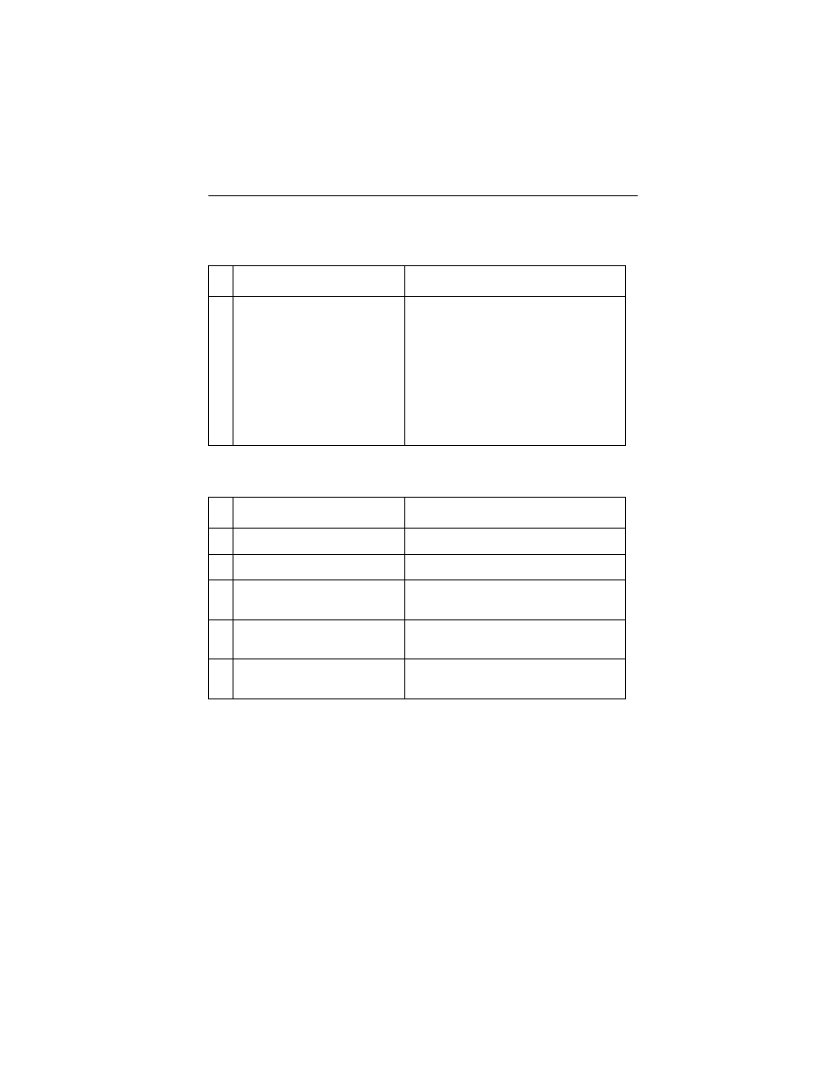
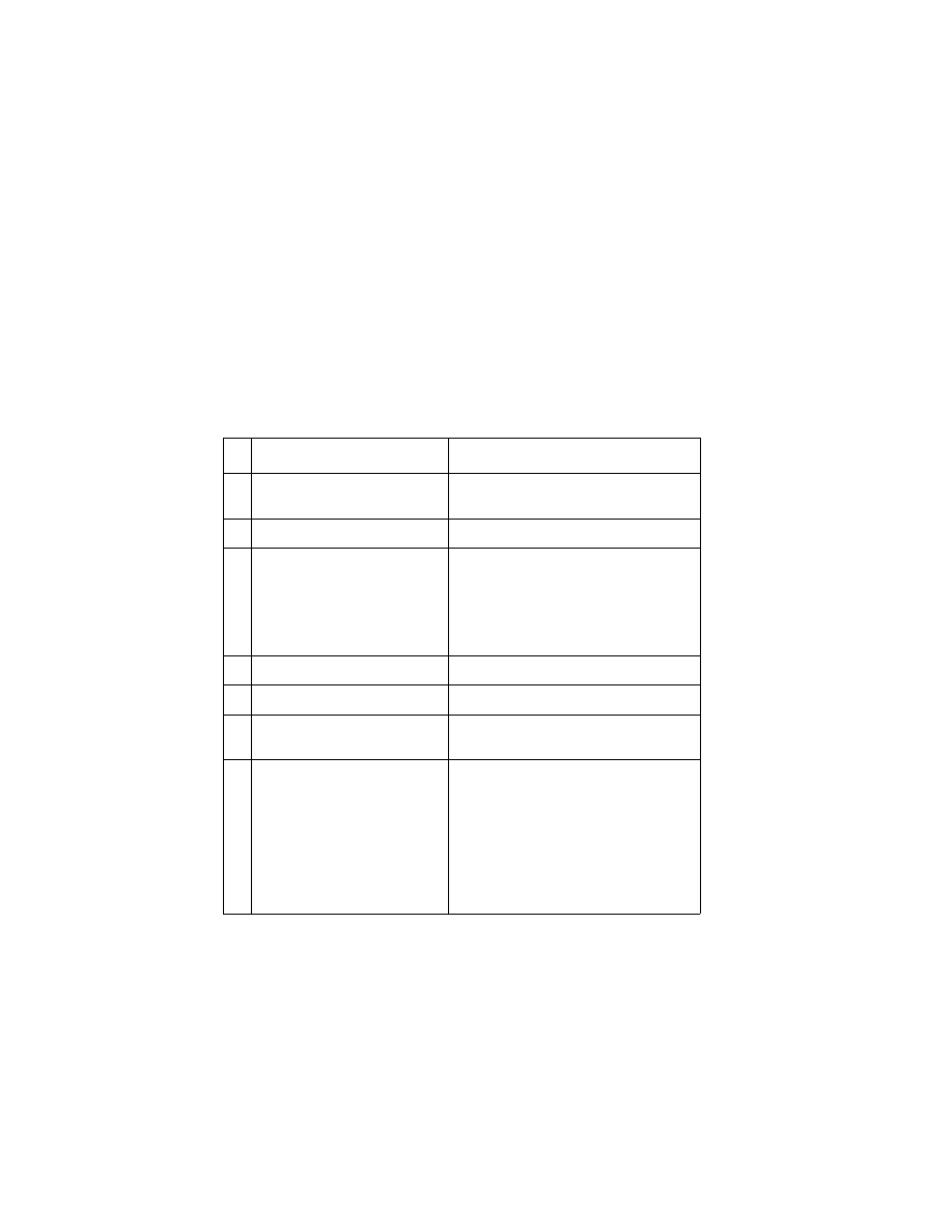
Error Indicator Table
Error
Code
Number of
Power Light
Flashes
Action
64
65
7
Replace the Code Module and/or system
board
66 to
78
6
Replace the Code Modules and/or system
board
No
Log
8
Replace the Code Module and/or system
board
79
9
Replace the Code Module and/or the system
board
80
2
Go to the
.
81
1
Go to the
85
3
Go to the
89
4
Go to the
90
5
Go to the
127
and
up
10
Go to the
.

4076-0WJ
5
Power-on-self-test (POST) Sequence
When you turn the printer on it performs a POST. Turn your machine
on and check for a correct POST operation by observing the follow-
ing:
1. The power light comes on.
2. The paper feed gears turn.
3. The carrier moves to the left and right at least one time.
4. The maintenance station cleans and caps the print head.
5. All motors stop and the power light stays on.
If your machine completes POST with no errors, go to the
, locate your symptom and take the indicated
action.
If your machine does not complete POST locate your symptom in
the following table and take the indicated action
POST Symptom Table.
Symptom
Action
No Power On light and no motors
run
Go to the
Feeds paper
Go to the
.
Paper feed gears do not turn
Go to the
Carrier doesn’t move
Go to the
Maintenance station doesn’t move
Go to the
.
The carrier moves then error 85
appears
Replace the system board
4076-0WJ
Diagnostic Information
6
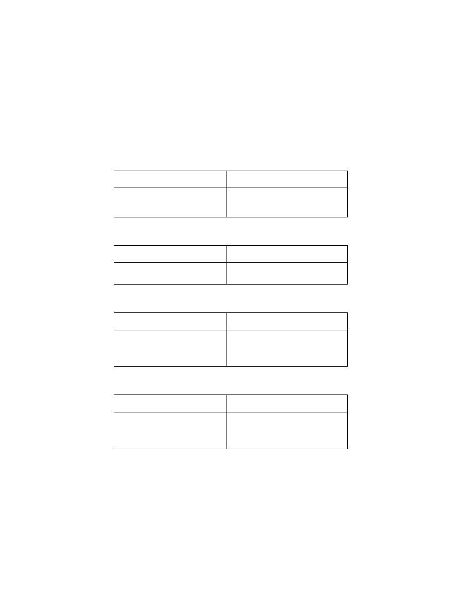
Symptom Tables
Locate your symptom in the following tables and take the appropri-
ate action.
Carrier Transport Problems
Communications Problem
Maintenance Station Problems
Operator Panel Problems
SYMPTOM
ACTION
• No carrier movement
• Slow carrier movement
• Carrier stops
Go to the
SYMPTOM
ACTION
Printer not communicating with
host.
Go to the
SYMPTOM
ACTION
• Maintenance station doesn’t
move
• Fails to cap the print head
• Fails to clean the print head
Go to the
.
SYMPTOM
ACTION
• Panel light(s) not working
• Panel button(s) not working
• Power Light is the only light that
comes on
Go to the
4076-0WJ
7
Paper Feed Problems
Power Problems
Print Quality Problems
SYMPTOM
ACTION
Paper fails to stop at first print
line
Go to the
• Fails to pick paper
• Picks more than one sheet of
paper
• Picks paper but fails to feed
• Paper jams
• Paper fails to exit
• Noisy paper feed
Go to the
Envelopes fail to feed
Go to the
Paper skews
Go to the
SYMPTOM
ACTION
No power in machine, no Power
On light, no motors
Go to the
SYMPTOM
ACTION
• Voids in characters
• Light print
• Prints off the page
• Prints satellites
• Carrier moves but does not print
• Print head drying out prema-
turely
• Vertical alignment off
Go to the
• Ink smearing
• Vertical streaks on paper
• Print lines crowded
Go to the
4076-0WJ
Diagnostic Information
8
Service Checks
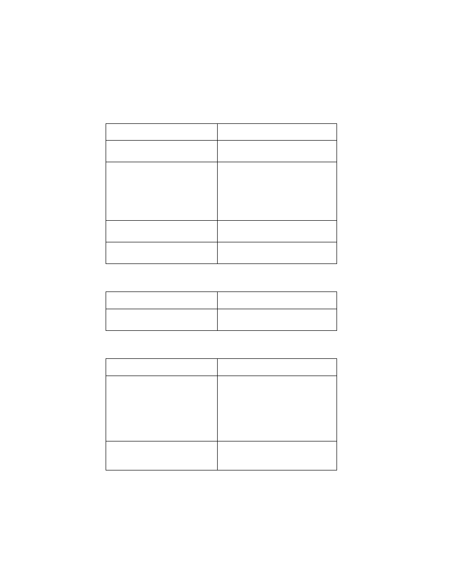
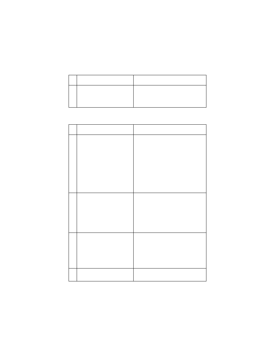
Envelope Feed Service Check
First Print Line Service Check
FRU OR PROCEDURE
ACTION
1
Envelope Loading
Be sure the envelope guides have
been turned to the envelope load
positions
Be sure the envelope guides are
against the envelopes
Go to and perform the
.
FRU OR PROCEDURE
ACTION
1
End-of-Forms Flag
Check the flag for binds or damage.
2
End-of-Forms Sensor
Check the sensor for dirt.
3
System Board
If the paper does not stop at the first
writing line, replace the system board.
4
Feed Arm Assembly
Check all parts of the feed arm
assembly for binds, wear, or damage.
5
Operator Panel
Go to the
4076-0WJ
9
Maintenance Station Service Check
The maintenance station has two functions:
1. Cleans the print head nozzles during the print operation.
2. Seals the print head when it is not being used to prevent the noz-
zles from drying.
Note: if the failure remains, replace the system board.
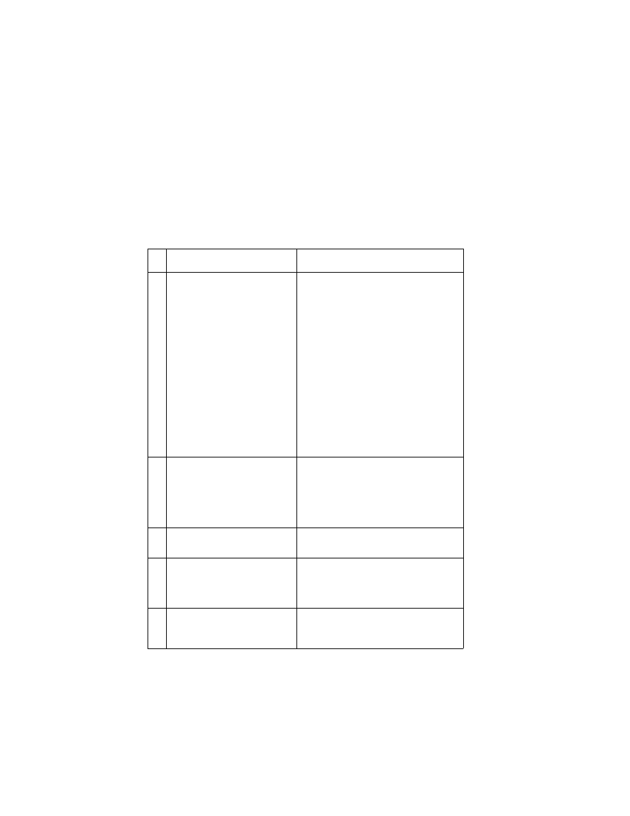
FRU OR PROCEDURE
ACTION
1
Maintenance Drive Assem-
bly
Disconnect J4 from the system board.
Check for 18 ohms (±4 ohms)
between pins 1 and 2 at the motor. If
the reading is incorrect, replace the
maintenance drive assembly,
Check for motor pins shorted to the
motor housing. If you find a shorted
pin, replace the maintenance drive
assembly. If the symptom remains,
replace the system board.
A bind in the drive assembly can pre-
vent the motor from turning. Check for
binds and loose or worn parts in the
drive assembly. Also check the motor
gear
2
System Board
Turn the printer off and disconnect J4
from the system board. Turn the
machine on and check for a pulse of
15 V dc between J4-1 and ground on
the system board as the machine
goes through POST.
3
Maintenance Rocker
Assembly
Check for binds or wear.
4
Wiper
A worn wiper will cause degraded
print quality just after a maintenance
cleaning. Check for loose or worn
wiper.
5
Cap
A worn cap will cause the print head
nozzles to dry and clog. Check for
loose or worn cap.
4076-0WJ
Diagnostic Information
10
Operator Panel Service Check
Paper Feed Service Check
If your machine does not have paper jam problems, go on to the ser-
vice check. If your machine does have a paper jam problem, exam-
ine the machine for the following before you begin the service check.
Check the entire paper path for obstructions.
•
Make sure there is not too much paper in the ASF.
•
Make sure the correct type of paper is in the machine.
•
Check for static in the paper.
•
Make sure the rear of the carrier guide is on top of the paper
guide.
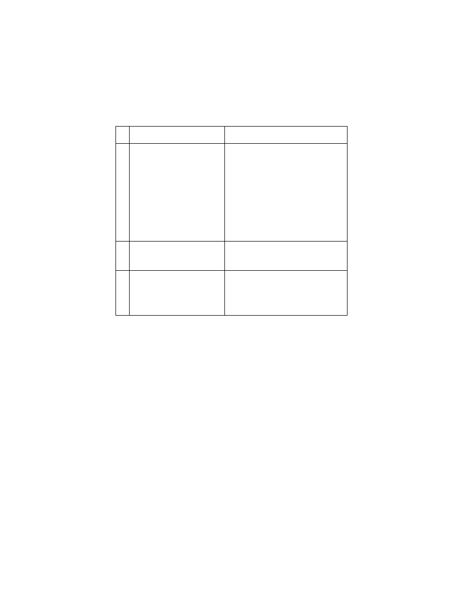
FRU OR PROCEDURE
ACTION
1
Power Supply
Disconnect J11 from the system
board and check the following volt-
ages on the power supply cable:
J11-1 to GND = +5V dc
J11-3 to GND = +24 V dc
If you do not have correct voltage,
replace the power supply. Be sure to
unplug the machine before you recon-
nect the power supply to the system
board.
2
System Board
Turn the printer on Check for +5 V dc
at test point CE/TP near the operator
panel connector on the system board
3
Operator Panel Card
Operator Panel Cable
Check the operator panel cable for
continuity. If the cable is good,
replace the operator panel. If the
symptom remains, replace the sys-
tem board.
4076-0WJ
11
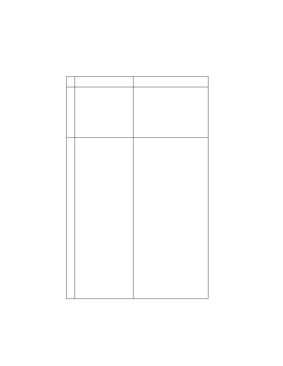
FRU OR PROCEDURE
ACTION
1
System Board
With J5 disconnected and power on,
check for +24 V dc between J5-3 and
ground, and between J5-4 and
ground on the system board. If the
voltage is not present, check for
motor pins shorted to the motor hous-
ing. If you find a shorted pin, replace
the motor. If you still have a failure
after replacing the motor, replace the
system board.
2
Paper Feed Motor
A noisy or chattering motor or a motor
that fails to turn, can be caused by:
• An open or short in the motor
• An open or short in the motor driver
on the system board
• A bind in the paper feed mechanism
Check for 100 ohms (±20 ohms)
between the following pins on the
motor:
Pin 1 to Pin 4
Pin 2 to Pin 4
Pin 3 to Pin 5
Pin 3 to Pin 6
If the readings are incorrect, replace
the motor. Check for motor pins
shorted to the motor housing. If you
find a shorted pin, replace the motor.
If the failure remains, replace the sys-
tem board.
Although the paper feeds in a forward
direction only, the paper feed motor
turns in two directions. If the paper
feed motor turns in one direction only,
replace the system board. Binds in
the paper feed motor or gear train can
cause intermittent false paper jam
errors. Remove the paper feed motor
and check the shaft for binds Also
check for loose or worn motor gear

4076-0WJ
Diagnostic Information
12
3
Gears
Check for binds in the gear train and
paper feed mechanism. To do this,
rotate the largest gear by hand. If you
notice a bind isolate it by removing
the small idler gear on the outside of
the right side plate. Replace any worn
or binding gears, rollers, or bearings.
4
Feed Arm Assembly
At the beginning of the paper feed
operation, the paper feed motor
reverses momentarily to allow the
feed arm pawl to drop off the home
position notch in the ASF side plate. If
the pawl fails to drop off the notch,
check the feed arm assembly for
binds, and worn or broken parts.
5
Auto Sheet Feeder
Check the following for wear or dam-
age:
Pick Rollers
Envelope Bucklers
All parts inside the left and right edge
guides
6
End-of-Forms Flag
Check for binds or damage.
7
Star Rollers
Check for worn or binding rollers.
Check for broken star roller springs.
8
Ejectors
After the paper exits from the exit roll-
ers, the paper feed motor reverses
causing the feed arm pawl to restore
to the home position in the ASF side
plate. At the same time, the paper
ejectors move the last sheet of paper
into the exit tray. If the ejectors do not
move or restore, check them for worn,
loose, or broken parts.
FRU OR PROCEDURE
ACTION
4076-0WJ
13
Paper Path Service Check
Examine the machine for the following before you begin this service
check:
•
Check the entire paper path for obstructions.
•
Be sure the paper guides are not worn or broken and are posi-
tioned against the paper without binding or buckling the paper.
•
Be sure the correct type of paper is in the machine.
•
Be sure the rear of the carrier guide is on top of the paper guide.
FRU OR PROCEDURE
ACTION
1
Large and Small Feed Roll-
ers
Check for wear and binds.
2
Large Feed Roller Springs
Check for damage.
3
Auto Sheet Feeder
Check the following for wear or dam-
age:
Envelope Bucklers
All parts inside the left and right edge
guides
4
End-of-Forms Flag
Check for binds or damage.
5
Exit Roller
Check for wear or binds.
6
Star Rollers
Check for wear or binds. Check for
broken star roller springs
7
Ejectors
After the paper exits from the exit roll-
ers, the paper feed motor reverses
causing the feed arm pawl to restore
to the home position in the ASF side
plate. At the same time, the paper
ejectors move the last sheet of paper
into the exit tray. If the ejectors do not
restore, check them for worn, loose,
or broken parts.
4076-0WJ
Diagnostic Information
14
Parallel Port Service Check
Power Service Check
FRU OR PROCEDURE
ACTION
1
Parallel Port
Run a test page to be sure the printer
can print. Run the
. If the test fails, replace
the system board.
FRU OR PROCEDURE
ACTION
1
Power Supply
Disconnect J11 from the system
board and check the following volt-
ages on the power supply cable:
J11-1 to GND = +5V dc
J11-3 to GND = +24 V dc
If you do not have correct voltage,
replace the power supply. Be sure to
unplug the machine before you recon-
nect the power supply to the system
board.
2
Operator Panel
With the machine unplugged and the
power button depressed, check for 0
ohms at J10-2 on the front of the
operator panel connector. If the read-
ing is incorrect, check the operator
panel cable for continuity. If the cable
has continuity, replace the operator
panel.
3
Print Head Cable
Parallel Cable
Turn off the printer. Disconnect one of
the listed components and turn on the
printer. Look for a symptom change.
Check the failing part for shorts and
replace as necessary. Repeat this
procedure for the remaining listed
parts.
4
System Board
If the symptom has not changed,
replace the system board.
4076-0WJ
15
Print Quality Service Check
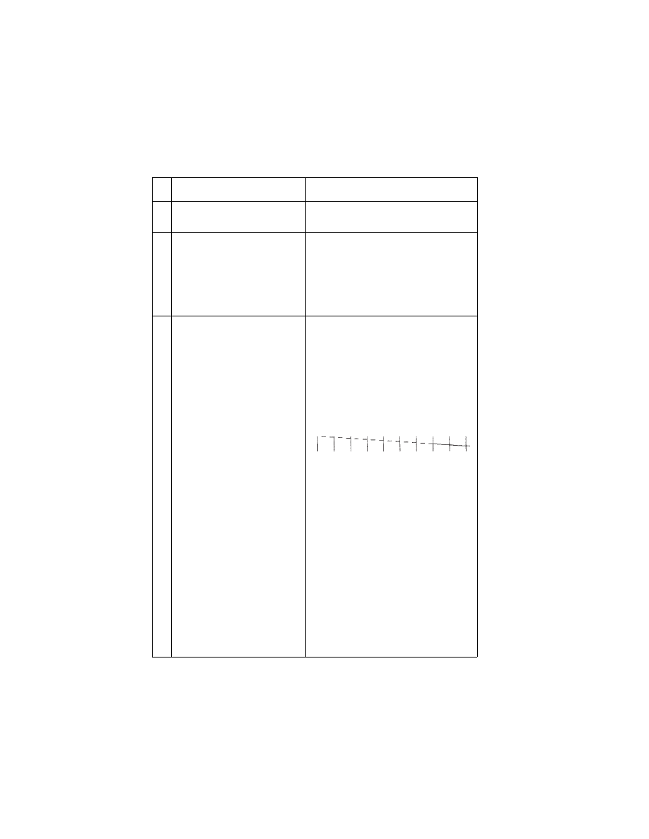
FRU OR PROCEDURE
ACTION
1
Print Cartridge
Be sure the machine has a known
good print cartridge.
2
Print Head Carrier Assembly
Reseat the print head cable in the
system board and check the following
parts for wear or damage:
Print Cartridge Latch
Latch Spring
Carrier
3
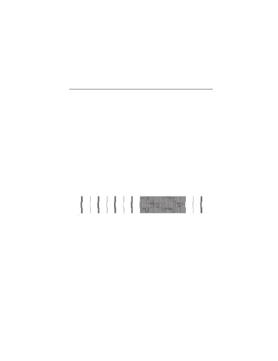
Purge Test
Perform the
Look for a break in the diagonal line
at the bottom of the test pattern. A
broken line indicates one or more
print nozzles are not working. Run the
test again to verify the failure If there
are even breaks in the diagonal line
similar to the pattern shown below,
replace the system board.
If there is a single break or random
breaks in the diagonal line check the
following:
• Print head cable - check the gold-
plated contacts on the end of the
cable that connects to the carrier for
dirt and wear. Use only a clean dry
cloth to clean the contacts. Also
check the cable for damage. You
may need to remove the cable from
the carrier to inspect it.
• Rubber Backer - a worn rubber
backer will result in poor contact
between the
print head cable and
the print cartridge. Check the rub-
ber backer for wear

4076-0WJ
Diagnostic Information
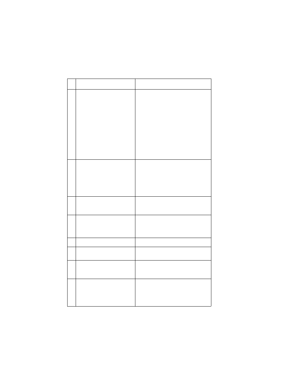
16
4
Maintenance Station
Intermittent nozzle failures can be
caused by worn parts in the mainte-
nance station. Go to and perform the
“Maintenance Station Service Check”
on page 9
, then return to this check.
5
Paper Feed
Ink smudging and smearing can be
caused by paper problems or prob-
lems in the paper feed area. Check:
• Correct type of paper is in the
machine. Also check the paper for
curl and wrinkles.
• Feed roller for wear, dirt, or loose-
ness
• Gears for wear or binds
• Paper path for obstructions
• Star rollers for binds or dirt. The exit
roller and star rollers keep tension
on the paper by moving slightly
faster than the feed rollers. A bind-
ing star roller can put vertical marks
on the paper.
6
Transport
Blurred print and voids can be caused
by problems in the transport area.
Check the following:
• Transport belt for wear.
• Carrier guide and carrier guide rod
for wear or dirt.
• Idler pulley parts for wear, damage,
or looseness.
• Encoder strip for wear or dirt.
7
Bi-Directional Alignment
Uneven vertical lines can be adjusted
by performing the
Alignment Adjustment” on page 22
FRU OR PROCEDURE
ACTION
4076-0WJ
17
Transport Service Check
FRU OR PROCEDURE
ACTION
1
Transport Motor
Check the motor for binds, or loose
motor pulley.
Disconnect the transport motor (J6)
from the system board. Check for 8 to
18 ohms between pins 1 and 2 on the
motor cable. If the reading is incor-
rect, replace the motor.
Check for motor pins shorted to the
motor housing. If you find a pin
shorted to the housing, replace the
motor. If the failure remains, replace
the system board.
2
System Board
Turn the printer off and disconnect J6
from the system board. Turn the
printer on and check for a pulse of 3
to 5 V dc between J6-1 and ground
and between J6-2and ground on the
system board as the machine goes
through POST.
3
Carrier Rod
Clean the carrier rod. Note: Do not
lubricate the rod or the carrier rod
bearings.
4
Transport Belt
Carrier Guide or Rod
Idler Pulley Parts
Cable Clip
Check for worn, loose or broken
parts. Check for obstructions blocking
carrier movement.
5
Encoder Strip
Check for wear and dirt.
6
Print Head Cable
Be sure connector J1 is fully seated.
Check the cable for damage.
7
Encoder Strip
Print Head Cable
System Board
Perform the
. If you cannot enter the test,
replace the system board.
8
Maintenance Station
A problem with the maintenance sta-
tion can cause carrier movement
problems at the right margin. Go to
the
Diagnostic Aids
18
4076-0WJ
Diagnostic Aids
3
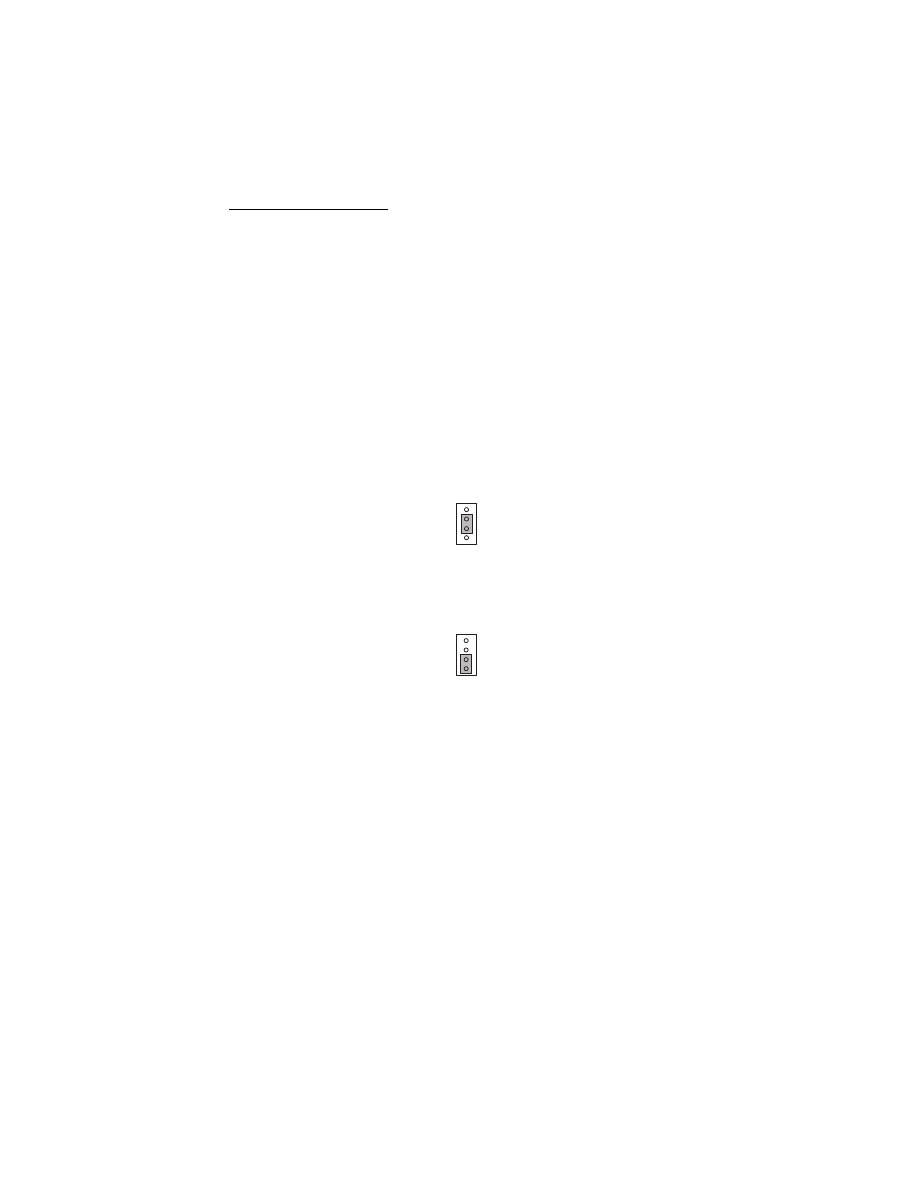
Use these diagnostic test procedures to verify a repair. The test pro-
cedures are entered by first turning the machine off, moving the two-
pin jumper on connector J12, then turning the machine on. J12 is
accessed through the door opening on the right side of the machine.
The test begins when the power button is pressed. Except for adjust-
ing the bi-directional alignment, the printer does not need to be
attached to a host to run the tests. To end a test, unplug the machine
or turn it off. The jumper pattern is illustrated for each test.
Return the jumper to position 2 and 3 after you complete testing.
Test Page
This test prints a test page followed by a shortened version of the
test page. The first line is the code level and code level date. The
next line is the print cartridge nozzle pattern. The six black lines are
the purge pattern. These tests are used to verify all print cartridge
nozzles are working. There should be no breaks in the diagonal line.
A break in the diagonal line indicates one or more nozzles are not
working.
The next patterns are the bi-directional patterns. The first pattern is
in letter quality mode. The second pattern is in the draft mode.
These patterns repeat to the bottom of the page. Both letter quality
and draft quality patterns should have straight vertical lines. If these
lines appear jagged, they need to be adjusted. Install the printer on a
PC and run the bi-directional alignment adjustment procedure on the
service manual diskette.
J12
J12
4076-0WJ
19
The numbers across the bottom of the page are used in manufactur-
ing. The last number on this line is the last occurring error code. This
number coincides with the flashing power on light and indicates the
type of error indication.
Additional pages print the same as the first page without the purge
pattern.
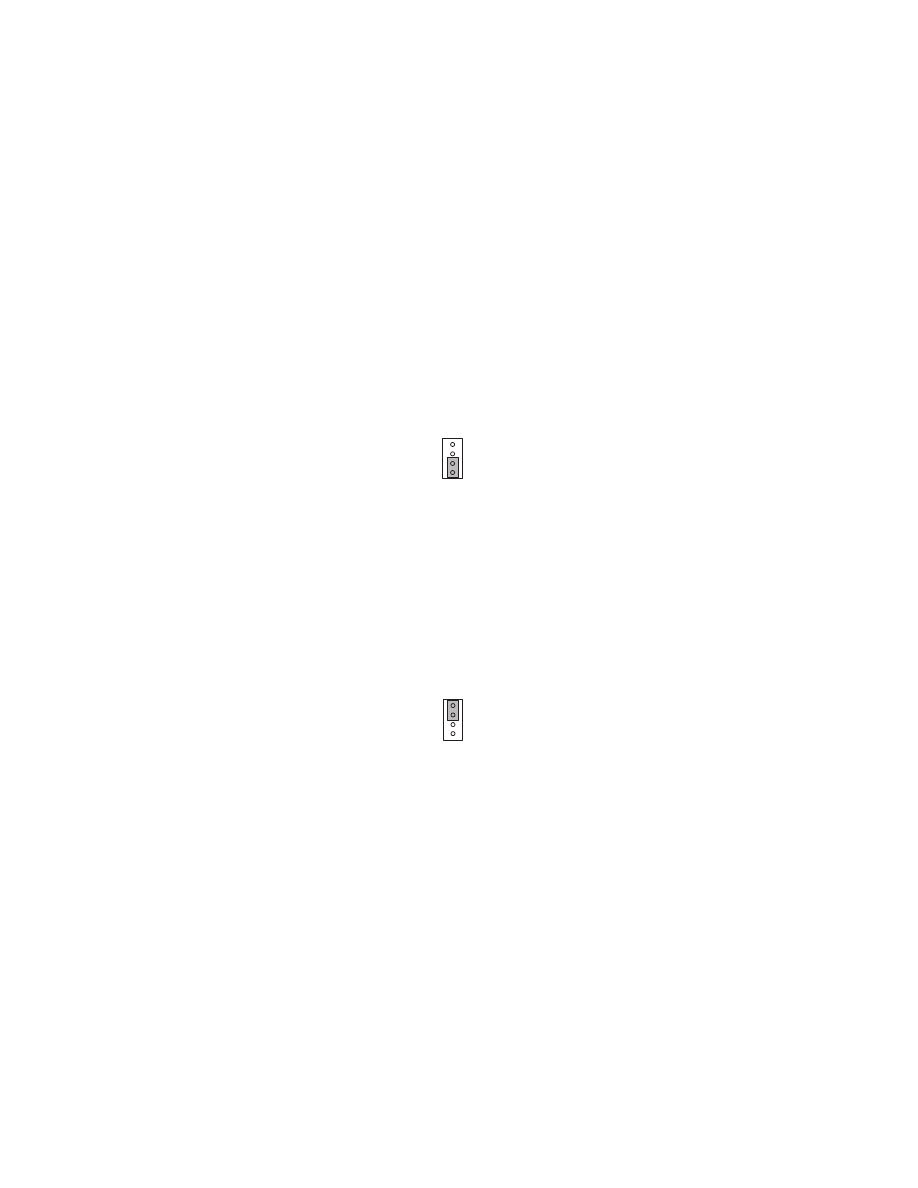
Parallel Port Test
This test requires a parallel port wrap plug. Install the wrap plug in
the parallel port before you start the test. This test performs a wrap-
around test between the printer parallel port and the parallel port
test connector. If the test is successful, the power on light flashes. If
the test is not successful, the power on light remains off.
Encoder Sensor Test
The printer motors are disabled during this test to allow you to man-
ually move the carrier to verify the encoder is working correctly. The
power on light flashes as the carrier is moved. If the power on light
does not flash, replace the print head cable. If the power on light
appears to break in the sequence, replace the encoder strip. If the
symptom remains, replace the system board.
J12
J12

4076-0WJ
Diagnostic Aids
20
Initialize Error Log
Use this procedure to reset the error log to zero. The paper sensor
must be open to perform this function. To do this, place a piece of
paper in the manual paper feed slot before you turn the machine on.
Resetting the error log allows you to track new errors. The error log
is especially helpful in diagnosing intermittent or difficult problems.
J12

Repair Information
21
4076-0WJ
Repair Information
4
This chapter explains how to make adjustments to the printer and
how to remove defective parts.
WARNING: Read the following before handling electronic parts.
Handling ESD-sensitive Parts
Many electronic products use parts that are known to be sensitive to
electrostatic discharge (ESD). To prevent damage to ESD-sensitive
parts, follow the instructions below in addition to all the usual pre-
cautions, such as turning off power before removing logic boards:
•
Keep the ESD-sensitive part in its original shipping container (a
special “ESD bag”) until you are ready to install the part into the
machine.
•
Make the least-possible movements with your body to prevent an
increase of static electricity from clothing fibers, carpets, and fur-
niture.
•
Put the ESD wrist strap on your wrist. Connect the wrist band to
the system ground point. This discharges any static electricity in
your body to the machine.
•
Hold the ESD-sensitive part by its edge connector shroud
(cover); do not touch its pins. If you are removing a pluggable
module, use the correct tool.
•
Do not place the ESD-sensitive part on the machine cover or on
a metal table; if you need to put down the ESD-sensitive part for
any reason, first put it into its special bag.
•
Machine covers and metal tables are electrical grounds. They
increase the risk of damage because they make a discharge
path from your body through the ESD-sensitive part. (Large
metal objects can be discharge paths without being grounded.)
•
Prevent ESD-sensitive parts from being accidentally touched by
other personnel. Install machine covers when you are not work-
ing on the machine, and do not put unprotected ESD-sensitive
parts on a table.
•
If possible, keep all ESD-sensitive parts in a grounded metal cab-
inet (case).
4076-0WJ
Repair Information
22
•
Be extra careful in working with ESD-sensitive parts when cold-
weather heating is used because low humidity increases static
electricity.
Adjustments
Bi-directional Alignment Adjustment
The bi-directional alignment can be checked by printing a test page.
The adjustment is correct when the vertical bars appear straight. To
adjust the bi-directional alignment:
1. Attach the printer to a PC operating in DOS.
2. Load paper in the Auto Sheet Feed.
3. Place the 4076 OWJ Service Diskette in the diskette drive. Type
the letter of the drive, colon, and adjust. For example; a:adjust.
4. A page loads and the bi-directional alignment pattern prints. The
pattern consists of three lines of vertical bars. The bars are
aligned when the adjustment is correct. The following sample
requires the center vertical bars to be moved to the right.
5. Follow the directions on the menu and move the center bar to
line up with the other two bars. Each time a selection is made,
the pattern will print.
6. When the alignment is correct, toggle over to the draft mode.
Follow the same procedure as above to align the bars in the draft
mode.
7. When you complete the adjustment and turn off the printer the
settings will be saved in the printer.

4076-0WJ
23
Removal Procedures
The following procedures are arranged in alphabetical order accord-
ing to the name of the printer part discussed. When there is artwork
to support a procedure, it follows the text.
Releasing Plastic Latches
Many of the parts are held in place with plastic latches. To remove
such parts, press the hook end of the latch away from the part to
which it is latched. The latches break easily. Release them carefully.
Never apply excessive force
when releasing the hook.
Hook
4076-0WJ
Repair Information
24
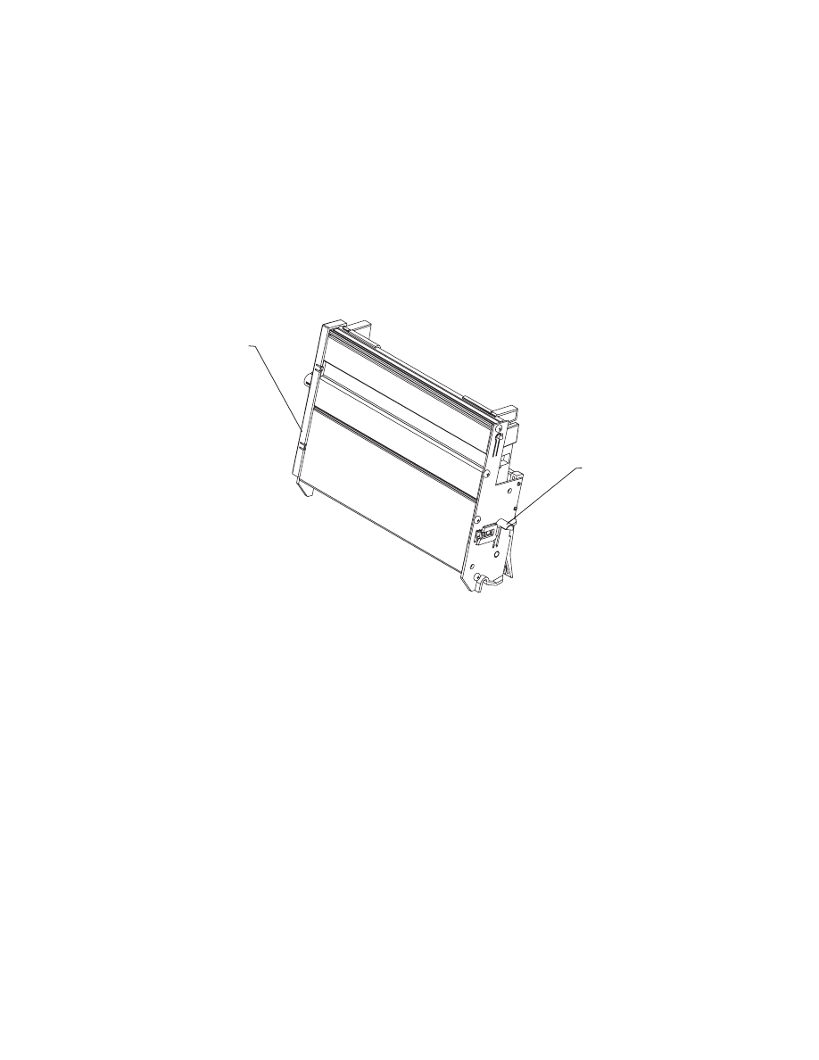
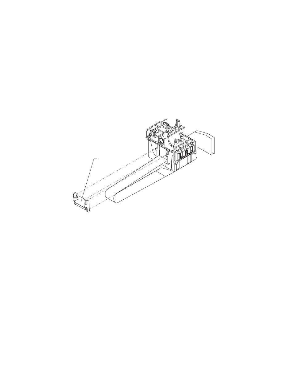
Auto Sheet Feed (ASF) Removal
1. Remove the top cover.
2. Push in the two latches [A] that secure the auto sheet feed to the
side frame, then lift up the auto sheet feed to remove it from the
machine.
When you reinstall the auto sheet feed, be sure the feed arm assem-
bly is vertical, with the feed pawl at the top.
ASF Envelope Buckler And Pick Roller Hub Removal
1. Remove the ASF.
2. Remove the inside C-clip from the pick roller shaft and pull the
shaft to the right far enough to remove the envelope bucklers
and pick rollers.
3. Remove the pick roller hubs from the bucklers.
A
A

4076-0WJ
25
ASF Right And Left Edge Guide Assemblies Removal
1. Remove the auto sheet feed.
2. Remove the manual insert tray by prying one of the side frames
away from it.
3. Remove the inside C-clip from the pick roller shaft and pull the
shaft out to the right.
4. Remove the pick roller and buckler assemblies.
5. Remove the paper load lever knob from the load lever.
6. Remove the auto sheet feed right side cover by prying up at the
slots in the rear.
7. Remove the paper load lever and shaft by pulling them out from
the right side of the ASF assembly. Be careful not to lose the
small gear on the left end of the shaft. When you reinstall this
shaft, it must be parallel with the ASF housing.
8. Pivot the guide assembly up and pry it off the back plate.
ASF Paper Load Lever Removal
1. Remove the auto sheet feed assembly.
2. Pull the paper load lever knob from the load lever.
3. Remove the auto sheet feed right side cover by prying up the
slots in the rear.
4. Remove the paper load lever from the mounting stud.
Carrier Removal
1. Remove the top cover.
2. Remove the print cartridge.
3. Disconnect the print head cables from the system board.
4. Move the carrier in line with the opening in the carrier transport
motor frame.
5. Reach through the opening and pull the belt from the carrier.
6. Rotate the carrier guide rod top-to-rear to unlock the rod
latches.Gently push the carrier guide rod latches, at each end of
the rod, to the rear and lift up the rod until the sensor on the car-
rier clears the encoder strip. Remove the carrier guide rod
through the opening in the left side frame. Be careful not to dam-
age the encoder strip.
7. Pull the ends of the print head cables into the machine, then
remove the cables from the 4 retainers in the paper guide start-
ing from the right.

4076-0WJ
Repair Information
26
Carrier Transport Belt Removal
1. Remove the top cover.
2. Move the carrier in line with the opening in the carrier transport
motor frame.
3. Reach through the opening and pull the belt from the carrier.
4. Remove the belt from the carrier transport motor pulley.
5. Remove the belt from the idler pulley and pull it through the
opening in the left side frame.
Note: When you reinstall the belt be sure to insert the bottom of
the belt into BOTH the lower and upper belt grips on the carrier.
DO NOT INSERT THE TOP OF THE BELT INTO THE TOP GRIP.
Carrier Guide Removal
You may remove the carrier guide without removing the covers if you
carefully follow this procedure.
1. Open and remove the access cover.
2. Remove the print cartridge.
3. Rotate the carrier guide rod top-to-rear to unlock the rod latches.
With the carrier centered, carefully release the 2 carrier guide
rod latches and lift the shaft slightly.
4. Unlatch the 2 carrier guide latches by pushing to the rear.
5. Gently push the carrier to the extreme right and remove the car-
rier guide.
When you reinstall the carrier guide, be sure the fingers on the bot-
tom of the carrier engage the groove on the carrier guide before you
snap the carrier guide rod down.
Carrier Transport Motor Removal
1. Remove the top cover.
2. Disconnect the carrier transport motor (J6) from the system
board.
3. Remove the 2 motor mounting screws and remove the motor.

4076-0WJ
27
Carrier Transport Motor Frame Removal
1. Remove the top cover.
2. Disconnect J6 from the system board.
3. Move the carrier in line with the opening in the carrier transport
motor frame.
4. Reach through the opening and pull the belt from the carrier.
5. Rotate the carrier guide rod top-to-rear to unlock the rod latches.
Gently push the carrier guide rod latches, at each end of the rod,
to the rear and lift up the rod until the sensor on the carrier clears
the encoder strip. Remove the carrier guide rod through the
opening in the left side frame. Be careful not to damage the
encoder strip.
A latch on the top front end of each side frame holds the transport
motor frame in place. Push up the latches on the front of the side
frames and pivot the carrier transport motor frame down and out of
the side frames.
Code Module Removal
1. Remove the top cover.
2. Disconnect the print head cables from the system board.
3. Disconnect connectors J4, J5, and J6 from the system board.
4. Remove the machine from the base. To do this, push the frame
latches out as you lift the machine from the base. Set the
machine aside.
5. Gently pry the code module from the system board.

4076-0WJ
Repair Information
28
Encoder Strip Removal
1. Remove the top cover.
2. Move the carrier in line with the opening on the carrier transport
motor frame.
3. Reach through the opening and pull the belt from the carrier.
4. Rotate the carrier guide rod top-to-rear to unlock the rod latches.
Gently push the carrier guide rod latches at each end of the rod
to the rear and lift up the rod until the sensor on the carrier clears
the encoder strip. Place the carrier on top of the paper guide.
5. Remove the encoder strip from the left mounting peg. To do this,
push the right latch slightly to the left.
6. Remove the encoder strip from the right latch.
When you install the encoder strip, be sure it is fully seated on the
left mounting peg.
End-of-forms Flag Removal
1. Remove the top cover.
2. Remove the ASF.
3. Open the print head cable connectors at the system board and
disconnect the cables.
4. Disconnect connectors J4, J5, and J6 from the system board. 5.
Remove the machine from the base. To do this, unlatch the 4
base frame latches. Lift the machine from the base and set it on
its front with the bottom facing you.
5. Pivot the weighted end of the end-of-forms flag through the
opening in the middle frame.
6. Lift the flag up and out of the machine.
Exit Roller Assembly Removal
1. Remove the top cover.
2. Remove the carrier transport frame.
3. Pivot the paper ejector pusher toward the front then pull it to
remove the paper ejector from the shaft.
4. Remove the bushing from the left end of the exit shaft. To do this,
pull the tab and rotate the bushing.
5. Slide the exit roller to the left and lift it out of the machine.

4076-0WJ
29
Feed Arm Assembly Removal
1. Remove the top cover.
2. Remove the auto sheet feed.
3. Remove the C-clip from the center of the large gear and remove
the feed arm assembly.
Inside Idler Gears Removal
1. Remove the top cover.
2. Remove the auto sheet feed.
3. Disconnect the print head cables from the system board.
4. Remove the paper guide.
5. Remove the C-clip from the feed arm assembly and remove the
feed arm assembly.
6. Pull the idler gears off the mounting studs.
Large Feed Roller Assembly Removal
1. Remove the top cover.
2. Disconnect the print head cables from the system board.
3. Disconnect connectors J4, J5, and J6 from the system board.
Remove the machine from the base. To do this, push the frame
latches out as you lift the machine from the base. Set the
machine aside.
4. Place the machine on its front with the bottom facing you.
5. Disconnect the 3 springs from the bottom of the middle frame
assembly.
6. Remove the large feed roller assembly.
Left Side Frame Removal
1. Remove the top cover.
2. Remove the print cartridge.
3. Remove the auto sheet feed.
4. Disconnect the print head cables from the system board.
5. Disconnect connectors J4, J5, and J6 from the system board.
6. Remove the machine from the base. To do this, push the frame
latches out as you lift the machine from the base. Set the
machine aside.
7. Move the carrier in line with the opening in the carrier transport
motor frame.
8. Reach through the opening and pull the belt from the carrier.

4076-0WJ
Repair Information
30
9. Rotate the carrier guide rod top-to-rear to unlock the rod latches.
Gently push the carrier guide rod latches, at each end of the rod,
to the rear and lift up the rod until the sensor on the carrier clears
the encoder strip. Remove the carrier guide rod through the
opening in the left side frame. Be careful not to damage the
encoder strip.
10. Pull the ends of the print head cables into the machine, then
remove the cables from the 4 retainers in the paper guide start-
ing from the right.
11. Disengage the left paper guide latch by carefully moving the rear
of the left side frame to the left.
12. Disengage the right side of the paper guide from the latch and lift
it from the machine.
13. A latch on the top front end of each side frame holds the trans-
port motor frame in place. Push up the latches on the front of the
side frames, then pivot the carrier transport motor frame down
and out of the side frames.
14. Place the machine on its back and push the left side frame latch
to the rear and remove the frame from the machine.
When you reinstall the paper guide, be sure the front edge goes
under the rear of the carrier guide. If the paper guide is on top of the
carrier guide, push down the front, bottom edge. It will snap under
the carrier guide.
To install the left side frame onto the middle frame, align the right
side frame latch with the latching surface on the middle frame before
you align the roller shafts and carrier guide. It may be easier to do
this with the machine on its right side.
Maintenance Drive And Rocker Assemblies Removal
1. Remove the top cover.
2. Remove the auto sheet feed.
3. Remove the right side frame.
4. Gently unlatch the maintenance assembly latches, and slide out
the maintenance drive assembly, then the rocker assembly.
When you reassemble the drive assembly, be sure the forks engage
the pins on the rocker assembly.

4076-0WJ
31
Middle Frame Removal
1. Remove the top cover.
2. Remove the print cartridge.
3. Remove the auto sheet feed.
4. Disconnect the print head cables from the system board.
5. Disconnect J4, J5, and J6 from the system board.
6. Remove the machine from the base. To do this, unlatch the 4
base frame latches. Lift the machine from the base and set it
aside.
7. Remove the paper ejectors from the middle frame.
8. Remove the left side frame.
9. Remove the exit shaft.
10. Remove the small feed roller shaft.
11. Remove the large feed roller shaft and springs.
12. Remove the end-of-forms flag.
13. Remove the right side frame.
14. Remove the maintenance station.
Operator Panel Removal
1. Remove the top cover.
2. Remove the 3 operator panel mounting screws.
3. Remove the operator panel.
Outside Idler Gears Removal
1. Remove the top cover.
2. Disconnect the print head cables from the system board.
3. Each gear is latched in place. Push up the latch and remove the
gear from the side frame stud by pulling the gear from the bot-
tom.

4076-0WJ
Repair Information
32
Paper Ejectors Removal
1. Remove the top cover.
2. Pivot the paper ejector pusher toward the front then pull it to
remove the paper ejector from the shaft.
3. Unsnap the paper ejectors from the middle frame.
Paper Feed Motor Removal
1. Remove the top cover.
2. Disconnect the paper feed motor from the system board.
3. Remove the motor mounting screws and remove the motor.
Paper Guide Removal
1. Remove the top cover.
2. Remove the auto sheet feed.
3. Disconnect the print head cables from the system board.
4. Pull the ends of the print head cables into the machine, then
remove the cables from the 4 retainers in the paper guide start-
ing from the right.
5. Disengage the left paper guide latch by carefully moving the rear
of the left side frame to the left.
6. Disengage the right side of the paper guide from the latch and lift
it from the machine.
Note: When you reinstall the paper guide, be sure the front edge
goes under the rear of the carrier guide. If the paper guide is on top
of the carrier guide, push down the front, bottom edge. It will snap
under the carrier guide.
4076-0WJ
33
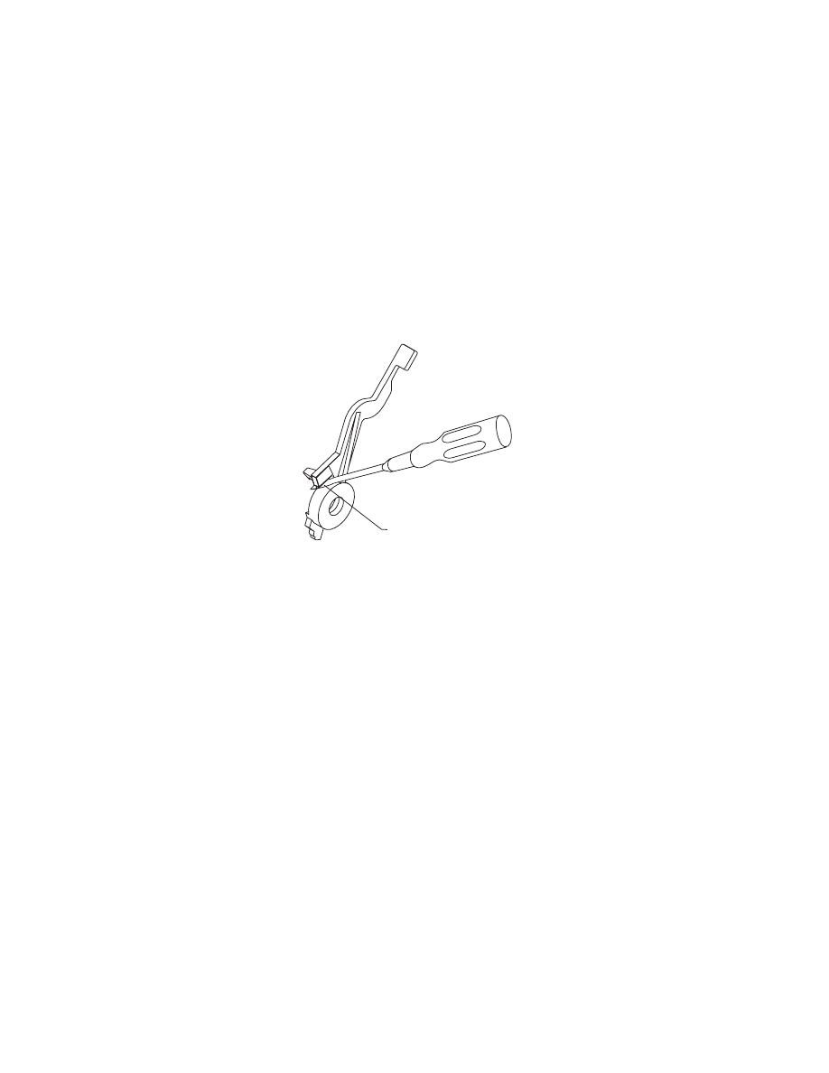
Paper Release Lever Removal
1. Remove the top cover.
2. Pull the paper release lever forward.
3. Place a screw driver into the slot [A] of the paper release lever.
Push the screw driver down to release the latch, then remove
the lever.
Power Supply Removal
1. Remove the top cover.
2. Disconnect the print head cables from the system board.
3. Disconnect connectors J4, J5, and J6 from the system board.
4. Remove the machine from the base. To do this, push the frame
latches out as you lift the machine from the base. Set the
machine aside.
5. Disconnect the power supply cable from the system board.
6. Remove the 4 power supply mounting screws and remove the
power supply.
NOTE: The fuse on the power supply is for safety pur- poses only. If
it blows, there is a bad component on the board. Do not replace the
fuse. A new fuse will not correct the failure.
A
4076-0WJ
Repair Information
34
Print Head Cable Removal
1. Remove the top cover.
2. Remove the print cartridge.
3. Remove the carrier.
4. Remove the cable clip [A] from the left side of the carrier.
5. Remove the pointer from the front of the carrier.
6. Remove the 2 sensor mounting screws.
7. Push down the 2 latches that secure the cradle to the carrier and
pull the cradle up from the carrier.
8. Remove the print head cable from the alignment pins.
The new cable comes without the folds in it. Place the new cable
next to the old cable and fold the new cable in the appropriate
places.
A

4076-0WJ
35
Right Side Frame Removal
1. Remove the top cover.
2. Remove the print cartridge.
3. Remove the auto sheet feed.
4. Disconnect the print head cables from the system board.
5. Disconnect connectors J4, J5, and J6 from the system board.
6. Remove the machine from the base. To do this, push the frame
latches out as you lift the machine from the base. Set the
machine aside.
7. Move the carrier in line with the opening in the carrier transport
motor frame.
8. Reach through the opening and pull the belt from the carrier.
9. Rotate the carrier guide rod top-to-rear to unlock the rod latches.
Gently push the carrier rod guide latches, at each end of the rod,
to the rear and lift up the rod until the sensor on the carrier clears
the encoder strip. Remove the carrier rod guide through the
opening in the left side frame. Be careful not to damage the
encoder strip.
10. Pull the ends of the print head cables into the machine, then
remove the cables from the 4 retainers in the paper guide start-
ing from the right.
11. Disengage the left paper guide latch by carefully moving the rear
of the left side frame to the left.
12. Disengage the right side of the paper guide from the latch and lift
the guide from the machine.
13. A latch on the top front end of each side frame holds the trans-
port motor frame in place. Push up the latches on the front of the
side frames, then pivot the carrier transport motor frame down
and out of the side frames.
14. Place the machine on its back, then unlatch the right frame latch
from the middle frame and remove the side frame.
NOTE: for reassembly you may want to remove the carrier guide and
reinstall it after you install the paper guide.
When you reinstall the paper guide, be sure the front edge goes
under the rear of the carrier guide. If the paper guide is on top of the
carrier guide, push down the front, bottom edge. It will snap under
the carrier guide.

4076-0WJ
Repair Information
36
To install the right side frame onto the middle frame, align the right
side frame latch with the latching surface on the mid frame before
you align the roller shafts and carrier guide. It may be easier to do
this with the machine on its left side.
Rubber Backer Removal
1. Remove the top cover.
2. Remove the print cartridge.
3. Remove the print head cable.
4. Remove the rubber backer from the carrier.
Small Feed Roller Assembly Removal
1. Remove the top cover.
2. Remove the auto sheet feed.
3. Remove the paper guide
4. Carefully remove the paper release lever.
5. Remove the bushing from the left end of the small feed roller
shaft. To do this, pull the tab and rotate the bushing.
6. Slide the small feed roller assembly to the left and lift it out of the
machine.
Star Roller Removal
1. Remove the top cover.
2. Move the carrier in line with the opening on the carrier transport
motor frame.
3. Reach through the opening and pull the belt from the carrier.
4. Rotate the carrier guide rod top-to-rear to unlock the rod latches.
Gently push the carrier guide rod latches at each end of the rod
to the rear and lift up the rod until the sensor on the carrier clears
the encoder strip. Place the carrier on top of the paper guide.
5. A latch on the top front end of each side frame holds the trans-
port motor frame in place. Push up the latches on the front of the
side frames and pivot the carrier transport motor frame down
and out of the side frames. Place the carrier transport motor
frame face down in front of the machine.
6. Remove the star roller by pushing it forward off the mounting peg
in the carrier transport motor frame.

4076-0WJ
37
System Board Removal
1. Remove the top cover.
2. Disconnect the print head cables from the system board.
3. Disconnect connectors J4, J5, and J6 from the system board.
Remove the machine from the base. To do this, push the frame
latches out as you lift the machine from the base. Set the
machine aside.
4. Disconnect the power supply cable from the system board.
5. Remove the 6 system board mounting screws and remove the
system board.
6. Run a test page to check the bi-directional alignment adjust-
ment.
4076-0WJ
Repair Information
38
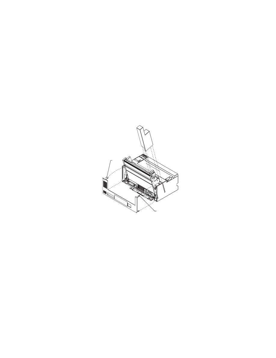
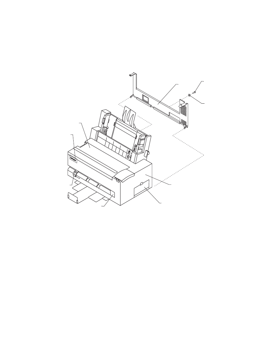
Top Cover Removal
1. Unplug the power cord and the interface cable from the back of
the printer.
2. Unlatch the auto sheet feed left cover by pushing it up from the
bottom, then slide it off the machine.
3. Turn the machine around to remove the rear cover. Remove the
screw and washer from the rear cover. Place a screwdriver in the
left slot [A] and push both latches latch down.
.
4. Pull the rear cover out until the latches clear the top cover, then
lift the cover off the base.
5. Turn the machine around to the front and pull the paper tray for-
ward.
6. Pull the top cover forward until it stops. Be sure the paper
release lever clears the slot in the top cover. The operator panel
cable is still connected, so carefully lift the cover off the base.
7. Set the cover down in front of the machine.
8. Pull the operator panel cable from the connector on the system
board.
NOTE: When you reinstall the top cover, pull out the exit tray to pre-
vent it from being trapped under the cover.
A
A
Connector Locations
39
4076-0WJ
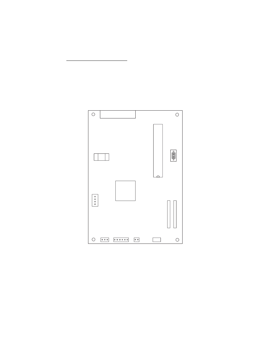
Connector Locations
9
This chapter shows the locations of major printer assemblies, con-
nectors, and ground straps.
System Board Connectors
J9
U20
J12
S1
U23
J7
J1
J2
1
1
1
1
J11
J6
J5
J4
J10
1
1
1
.CE/TP
1
4076-0WJ
Connector Locations
40
Connector
Connector Names
J1
Print Head Cable
J2
Print Head Cable
J4
Maintenance Motor
J5
Paper Feed Motor
J6
Transport Motor
J9
Parallel Port
J10
Operator Panel
J11
Power Supply
J12
Test Jumper
U20
Code Module

Preventive Maintenance
41
4076-0WJ
Preventive Maintenance
10
This chapter contains the lubrication specifications. Following these
recommendations can help prevent problems and maintain optimum
performance.
Lubrication Specifications
Lubricate only when parts are replaced or as needed, not on a
scheduled basis. Use no. 23 grease to lubricate the following:
•
All gear mounting studs
•
The right end of the exit roller at the right side frame
•
The right end of the small feed roller at the right side frame
•
The left end of the large feed roller at the left side frame
•
Both ends of the ASF pick roll shaft at the ASF side frames
•
Transport belt idler pulley hole
•
Inside surface of the transport idler pulley tension wedge where it
touches the left side frame.
Do not lubricate the carrier guide rod, or carrier guide rod bearings.

42
4076-0WJ
Parts Catalog
11
How To Use This Parts Catalog
•
SIMILAR ASSEMBLIES: If two assemblies contain a major-
ity of identical parts, they are broken down on the same list.
Common parts are shown by one index number. Parts
peculiar to one or the other of the assemblies are listed sep-
arately and identified by description.
•
AR: (As Required) in the Units column indicates that the
quantity is not the same for all machines.
•
NP: (Non-Procurable) in the Units column indicates that the
part is non-procurable and that the individual parts or the
next higher assembly should be ordered.
•
NR: (Not Recommended) in the Units column indicates that
the part is procurable but not recommended for field
replacement, and that the next higher assembly should be
ordered.
•
R: (Restricted) in the Units column indicates that the part
has a restricted availability.
•
NS: (Not Shown) in the Asm-Index column indicates that
the part is procurable but is not pictured in the illustration.
•
INDENTURE: The indenture is marked by a series of dots
located before the parts description. The indenture indi-
cates the relationship of a part to the next higher assembly.
For example:
INDENTURE RELATIONSHIP OF PARTS
(No dot) MAIN ASSEMBLY
(One dot) o Detail parts of a main assembly
(One dot) o Subassembly of the main assembly
(Two dot) o o Detail part of a one-dot subassembly
(Two dot) o o Subassembly of a one-dot subassembly
4076-0WJ
43
Assembly 1: Covers
2
6
5
3
1
4
7
8
9
4076-0WJ
44
Asm-
Index
Part
Number
Units
Description
1-1
1367099
1
Top Cover
-2
1367487
1
Access Cover Asm
-3
1367486
1
Font Card Door
-4
1367479
1
Rear Cover
-5
1367493
1
Left Output Guide
-6
1374401
1
Logo
-7
1
Screw, Parts Packet 1367169
-8
1
Washer, Parts Packet 1367169
-9
1374409
1
Microsoft at Work Label
4076-0WJ
45
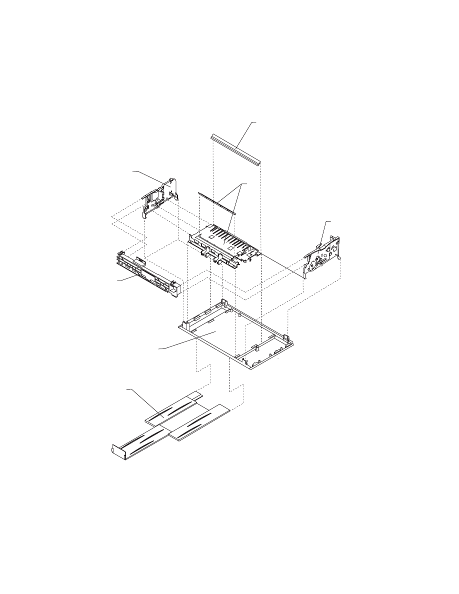
Assembly 2: Frames
2
3
4
1
6
5
7

4076-0WJ
46
Asm-
Index
Part
Number
Units
Description
2-1
1367489
1
Base Asm
-2
1367209
1
Left Side Frame
-3
1367219
1
Middle Frame Asm
-4
1367229
1
Right Side Frame
-5
1367309
1
Carrier Transport Motor Frame
-6
1367199
1
Exit Tray Asm
-7
1367079
1
Carrier Guide
4076-0WJ
47
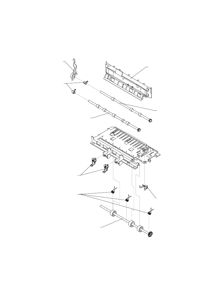
Assembly 3: Paper Feed
4
6
7
9
8
1
2
3
5
4076-0WJ
48
ASm-
Index
Part
Number
Units
Description
3-1
1367179
1
Paper Release Lever
-2
2
Bushing, Parts Packet1367169
-3
1367339
1
Paper Guide
-4
1367279
1
Small Feed Roller Asm
-5
1367289
1
Exit Roller Asm
-6
1367266
1
Ejector B/M
-7
3
Spring, Parts Packet1367169
-8
1367049
1
End of Forms Flag
-9
1367269
1
Large Feed Roller Asm
4076-0WJ
49
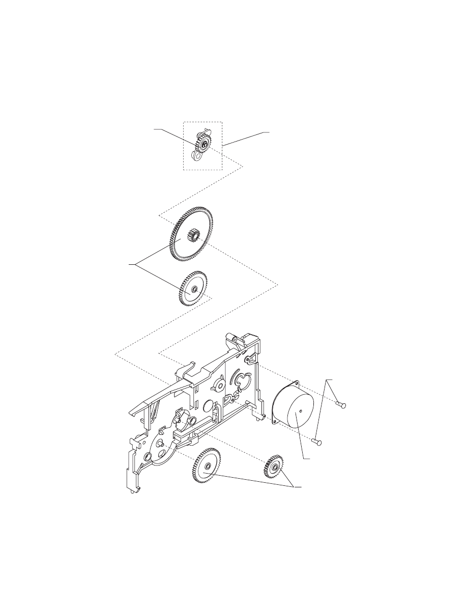
Assembly 3: Paper Feed (Cont.)
11
13
12
11
10
14

4076-0WJ
50
Asm-
Index
Part
Number
Units
Description
3-10
1367239
1
Paper Feed Motor Asm
-11
1367249
1
Gears B/M
-12
1367259
1
Feed Arm Asm
-13
2
C-Clip, Parts Packet 1367169
-14
2
Screw, Parts Packet 1367169

4076-0WJ
51
Assembly 4: Electronics
4
5
4
3
2
1
8
6
7
9
10
11
4076-0WJ
52
Asm-
Index
Part
Number
Units
Description
4-1
1374402
1
System Board, (No Code Module)
-2
4
Screw, Parts Packet 1367169
-3
1367189
1
Power Supply
-4
4
Screw, Parts Packet 1367169
-5
2
Screw, Parts Packet 1367169
-6
2
Screw, Parts Packet 1367169
-7
1430317
1
Power Cord, US
-7
1342536
1
Power Cord, Argentina
-7
1339520
1
Power Cord, Austria
-7
1339520
1
Power Cord, Belgium
-7
1342514
1
Power Cord, Bolivia
-7
1342514
1
Power Cord, Brazil (LV)
-7
1342530
1
Power Cord, Brazil (HV)
-7
1430317
1
Power Cord, Canada
-7
1342534
1
Power Cord, Chile
-7
1342514
1
Power Cord, Columbia
-7
1342514
1
Power Cord, Costa Rica
-7
1339525
1
Power Cord, Denmark
-7
1342514
1
Power Cord, Ecuador
-7
1342514
1
Power Cord, El Salvador
-7
1339520
1
Power Cord, Finland
-7
1339520
1
Power Cord, France
-7
1339520
1
Power Cord, Germany
-7
1339520
1
Power Cord, Greece
-7
1342514
1
Power Cord, Guatemala
-7
1342514
1
Power Cord, Honduras
-7
1339520
1
Power Cord, Iceland
-7
1339519
1
Power Cord, Ireland
-7
1339521
1
Power Cord, Israel
-7
1339524
1
Power Cord, Italy
-7
1342514
1
Power Cord, Mexico
-7
1339520
1
Power Cord, Netherlands
-7
1342514
1
Power Cord, Nicaragua
-7
1339520
1
Power Cord, Norway
-7
1342514
1
Power Cord, Panama
-7
1342536
1
Power Cord, Paraguay
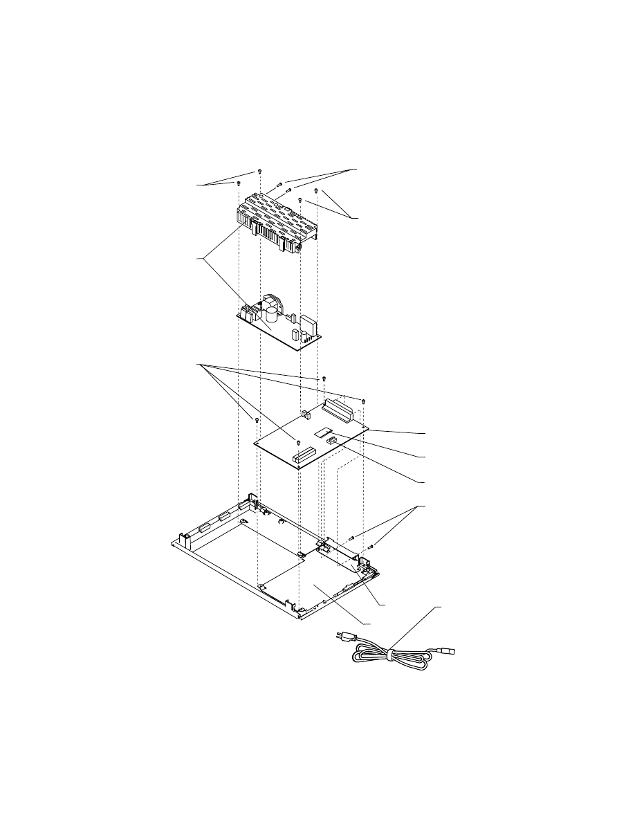
4076-0WJ
53
Assembly 4: Electronics (Cont.)
4
5
4
3
2
1
8
6
7
9
10
11
4076-0WJ
54
Asm-
Index
Part
Number
Units
Description
-7
1342514
1
Power Cord, Peru
-7
1339520
1
Power Cord, Portugal
-7
1339523
1
Power Cord, South Africa
-7
1339520
1
Power Cord, Spain
-7
1339520
1
Power Cord, Sweden
-7
1339522
1
Power Cord, Switzerland
-7
1339520
1
Power Cord, Turkey
-7
1339519
1
Power Cord, United Kingdom
-7
1342536
1
Power Cord, Uruguay
-7
1342514
1
Power Cord, Venezuela
-8
1374399
1
Code Module
-9
1374327
1
Ground Plane
-10
1374328
1
ESD Shield
-NS
1
Jumper, 2-Pin, Parts Packet
1367169
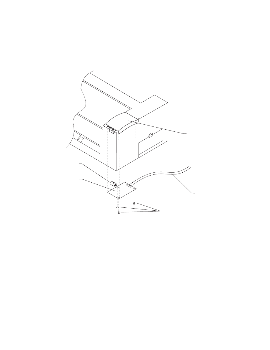
4076-0WJ
55
Assembly 4 Electronics (Cont.)
13
10
11
9
12
4076-0WJ
56
Asm-
Index
Part
Number
Units
Description
4-9
1374403
1
Operator Panel Card
-10
1374404
1
Operator Panel Cable
-11
3
Screw, Parts Packet 1367169
-12
1374408
1
Power Button
-13
1374406
1
Op Panel Cover
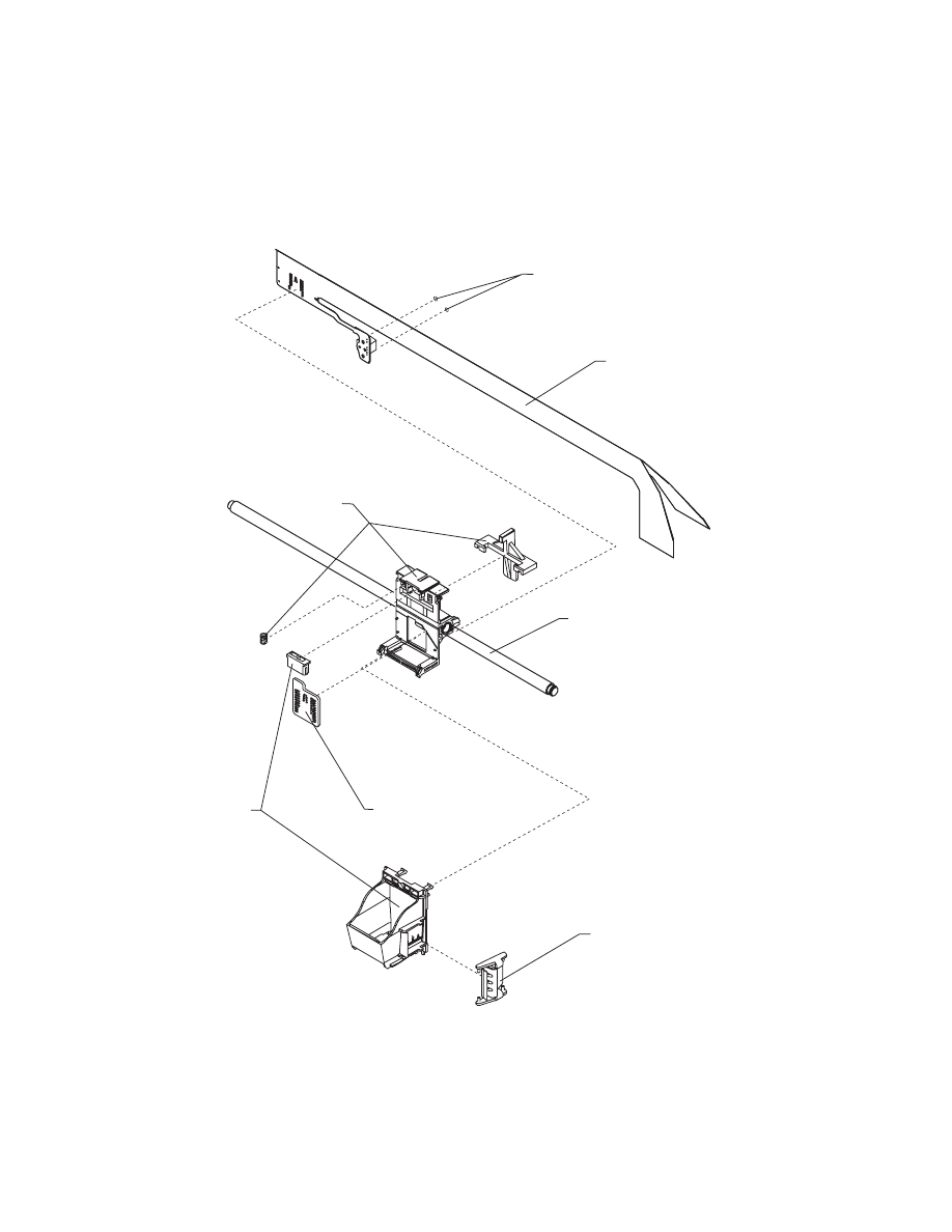
4076-0WJ
57
Assembly 5: Carrier
3
1
4
6
1
2
5
4076-0WJ
58
Asm-
Index
Part
Number
Units
Description
5-1
1367299
1
Print Head Carrier Asm
-2
1367149
1
Cable, Print Head
-3
2
Screw, Parts Packet 1367169
-4
1367109
1
Rubber Backer
-5
1367089
1
Guide Rod, Carrier
-6
1
Clip, Parts Packet 1367169
NS
1374338
1
Toroid, Non-Western Hemisphere
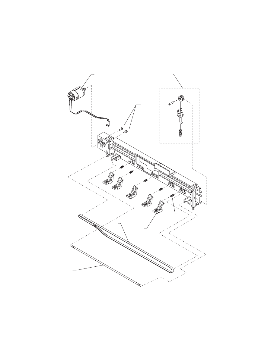
4076-0WJ
59
Assembly 6: Carrier Transport
1
2
4
5
3
6
7
4076-0WJ
60
Asm-
Index
Part
Number
Units
Description
6-1
1367319
1
Motor Asm
-2
2
Screw, Parts Packet 1367169
-3
1367359
1
Belt
-4
1367379
1
Encoder Strip
-5
1367349
1
Star Roller Asm
-6
5
Spring, Parts Packet 1367169
-7
1367329
1
Idler Pulley B/M
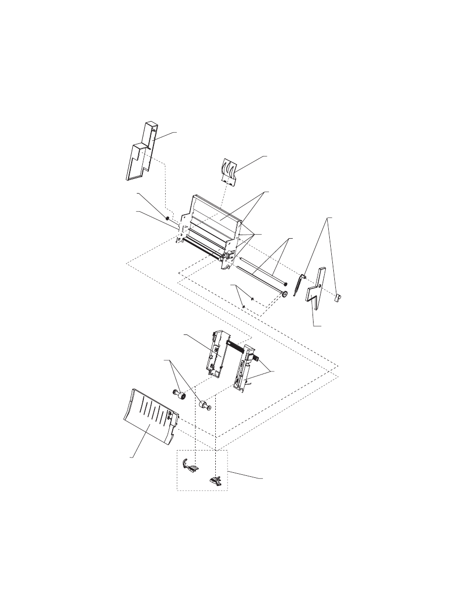
4076-0WJ
61
Assembly 7: Auto Sheet Feed
6
13
5
2
10
3
9
14
1
11
10
12
4
8
7
4076-0WJ
62
Asm-
Index
Part
Number
Units
Description
7-1
1367497
1
Right Edge Guide and Width Adjust
Strip
-2
1367498
1
Left Edge Guide Asm
-3
1367439
1
Upper Paper Support
-4
1367469
1
Pick Roll and Paper Load Shaft B/M
-5
1367463
1
Pick Roll Hub Asm
-6
1367449
1
Left Side Cover
-7
1367459
1
Right Side Cover
-8
1367029
1
Paper Load B/M
-9
1367019
1
Envelope Buckler B/M
-10
1367396
1
Side and Back Plate B/M
-11
1367249
1
Gears B/M
-12
2
E-Ring, Parts Packet 1367169
-13
4
Screw, Parts Packet 1367169
-14
1367429
1
Manual Insert Tray
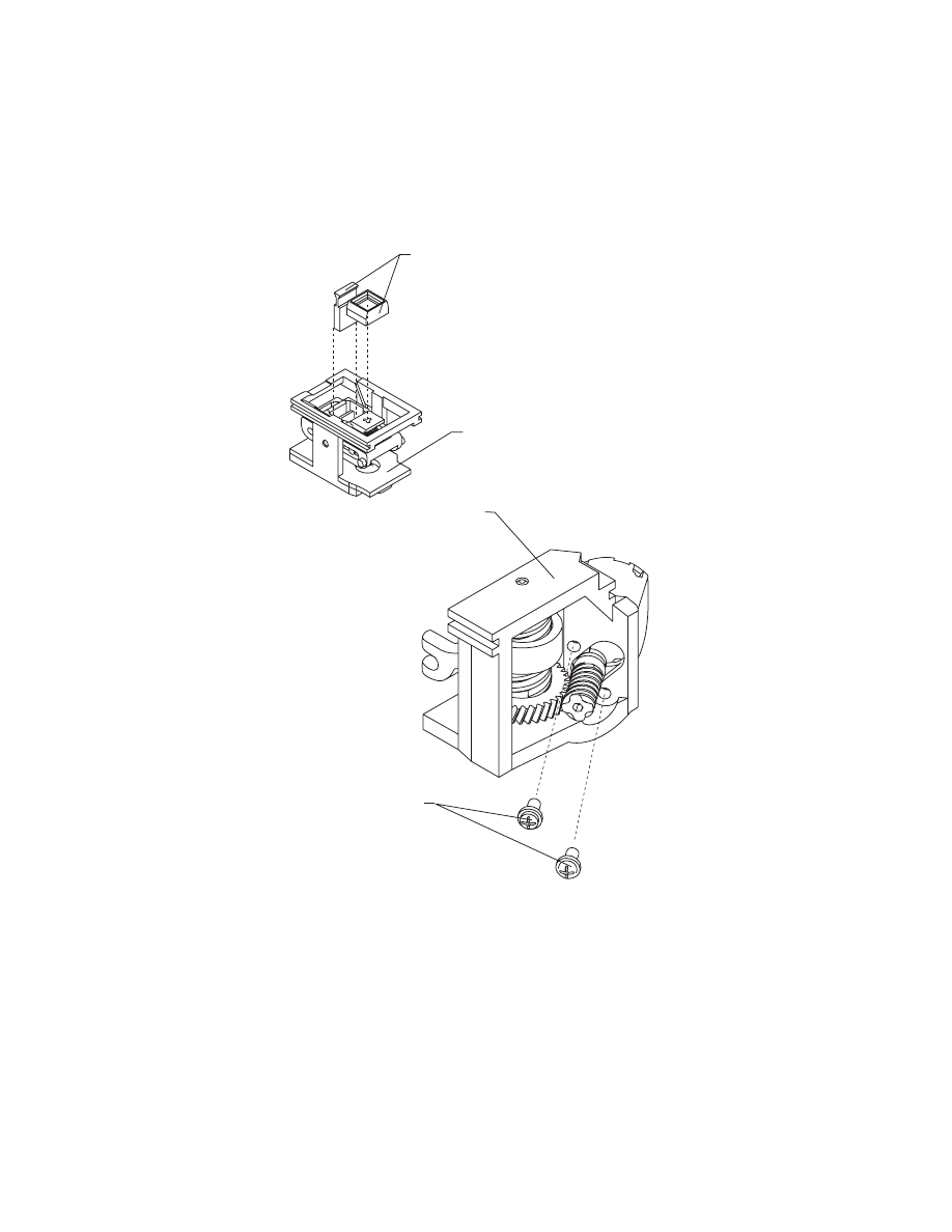
4076-0WJ
63
Assembly 8: Maintenance Station
3
1
4
2

4076-0WJ
64
Asm-
Index
Part
number
Units
Description
8-1
1367369
1
Rocker Asm
-2
1367399
1
Drive Asm
-3
1367389
1
Wiper and Cap B/M
-4
2
Screw, Parts Packet 1367169

65
4076-0WJ
Index
12
A
Abbreviatimons
Adjustments
ASF Envelope Buckler And Pick
Roller Hub Removal
ASF Paper Load Lever Removal
ASF Right And Left Edge Guide
Assemblies Removal
Assembly 1
Covers
Assembly 2
Frames
Assembly 3
Paper Feed
Assembly 4
Electronics
Assembly 5
Carrier
Assembly 6
Carrier Transport
Assembly 7
Auto Sheet Feed
Assembly 8
Maintenance Station
Auto Sheet Feed Removal
B
Bi-directional Alignment
Adjustment
C
Carrier Belt Removal
Carrier Guide Removal
Carrier Removal
Carrier Transport Belt Removal
Carrier Transport Motor Frame
Removal
Carrier Transport Motor
Removal
Carrier Transport Problems
Code Module Removal
Communications Problem
Connector Locations
D
Diagnostic Information
E
Encoder Strip Removal
End-of-forms Flag Removal
Envelope Feed Service Check
Error Indicator Table
Exit Roller Assembly Removal
F
Feed Arm Assembly Removal
First Print Line Service Check
G
General Information
H
Handling Esd-sensitive Parts
How To Use This Parts Catalog
I
Inside Idler Gears Removal

66
4076-0WJ
L
Large Feed Roller Assembly
Removal
Left Side Frame Removal
Lubrication Specifications
M
Maintenance Approach
Maintenance Drive And Rocker
Assemblies Removal
Maintenance Station Problems
Maintenance Station Service
Check
O
Operator Panel Problems
Operator Panel Removal
Operator Panel Service Check
Outside Idler Gears Removal
P
Paper Feed Problems
Paper Feed Service Check
Paper Path Service Check
Parallel Port Service Check
Parts Catalog
Plastic Latches
POST Sequence
POST Symptom Table.
Power Consumption
Power Problems
Power Service Check
Power-on-self-test
Power-on-self-test (Post)
Sequence
Preventive Maintenance
Print Quality Problems
Print Quality Service Check
R
Removal Procedures
S
Service Checks
Start
Symptom Tables
U
Unique Tools
Document Outline
- General Information
- Diagnostic Information
- Diagnostic Aids
- Repair Information
- Handling ESD-sensitive Parts
- Adjustments
- Removal Procedures
- Releasing Plastic Latches
- Auto Sheet Feed (ASF) Removal
- ASF Envelope Buckler And Pick Roller Hub Removal
- ASF Right And Left Edge Guide Assemblies Removal
- ASF Paper Load Lever Removal
- Carrier Removal
- Carrier Transport Belt Removal
- Carrier Guide Removal
- Carrier Transport Motor Removal
- Carrier Transport Motor Frame Removal
- Code Module Removal
- Encoder Strip Removal
- End-of-forms Flag Removal
- Exit Roller Assembly Removal
- Feed Arm Assembly Removal
- Inside Idler Gears Removal
- Large Feed Roller Assembly Removal
- Left Side Frame Removal
- Maintenance Drive And Rocker Assemblies Removal
- Middle Frame Removal
- Operator Panel Removal
- Outside Idler Gears Removal
- Paper Ejectors Removal
- Paper Feed Motor Removal
- Paper Guide Removal
- Paper Release Lever Removal
- Power Supply Removal
- Print Head Cable Removal
- Right Side Frame Removal
- Rubber Backer Removal
- Small Feed Roller Assembly Removal
- Star Roller Removal
- System Board Removal
- Top Cover Removal
- Connector Locations
- Preventive Maintenance
- Parts Catalog
- Index
Wyszukiwarka
Podobne podstrony:
Lexmark 3200 (4097) Color Jetprinter Service Manual
LEXMARK optraimage 725 4036 205 service manual
Lexmark Z 31 Color JetPrinter Service Manual
Lexmark 4092 Color JetPrinter 7000, 7200, 7200v Service Manual
Lexmark Medley 4012 0XX Service Manual
Lexmark 4078 00x Color JetPrinter 1020 Service Manual
Lexmark 4096 00x Color JetPrinter 1000, 1100 Service Manual
MX 100 PARTS & SERVICE MANUAL
LEXMARK x83 x85 scan print copy 4403 xxx service manual
LEXMARK 2070 color jetprinter 4090 001 service manual
Yamaha A 100 A Service Manual
LEXMARK 030 color jetprinter 4091 001 service manual
hplj 5p 6p service manual vhnlwmi5rxab6ao6bivsrdhllvztpnnomgxi2ma vhnlwmi5rxab6ao6bivsrdhllvztpnnomg
Oberheim Prommer Service Manual
więcej podobnych podstron