97
Integrated High Voltage Electronics to drive Microactuators
S.Heinz, C. Schlegel, H.-G. Symanzik, G. Ebest
One problem in driving microactuators working on electrostatic attraction are the sometimes
relatively high voltages needed to achieve a substantial deflection. The driving electronic circuits in
this field have to deliver voltages in the range from about 40 V up to 1000 V while simultaneously
perform well in terms of speed and power dissipation. Concepts based on integrated circuits are
leading together with micromachined components to completely miniaturized microsystems and
have a better designed performance in comparison with discrete components designs because of
their smaller parasitics. We are using a trench isolated process which has together with 15V CMOS
devices for doing analog and digital signal processing some DMOS (double diffused MOS)
Devices to be used in the output stages with a maximum Vds of 500 V. For our design purposes we
developed well performing DMOS models for circuit simulation. We chose a macro-modeling
approach for several reasons:
o There is no DMOS model widely available in SPICE type circuit simulators.
o The models should be portable to other SPICE type simulators.
o The models need not be scalable because the different DMOS devices are fixed in their layout
and are rather multiplied than scaled.
Our DMOS models include the nonlinear drain resistance of the JFET region as well as the non-
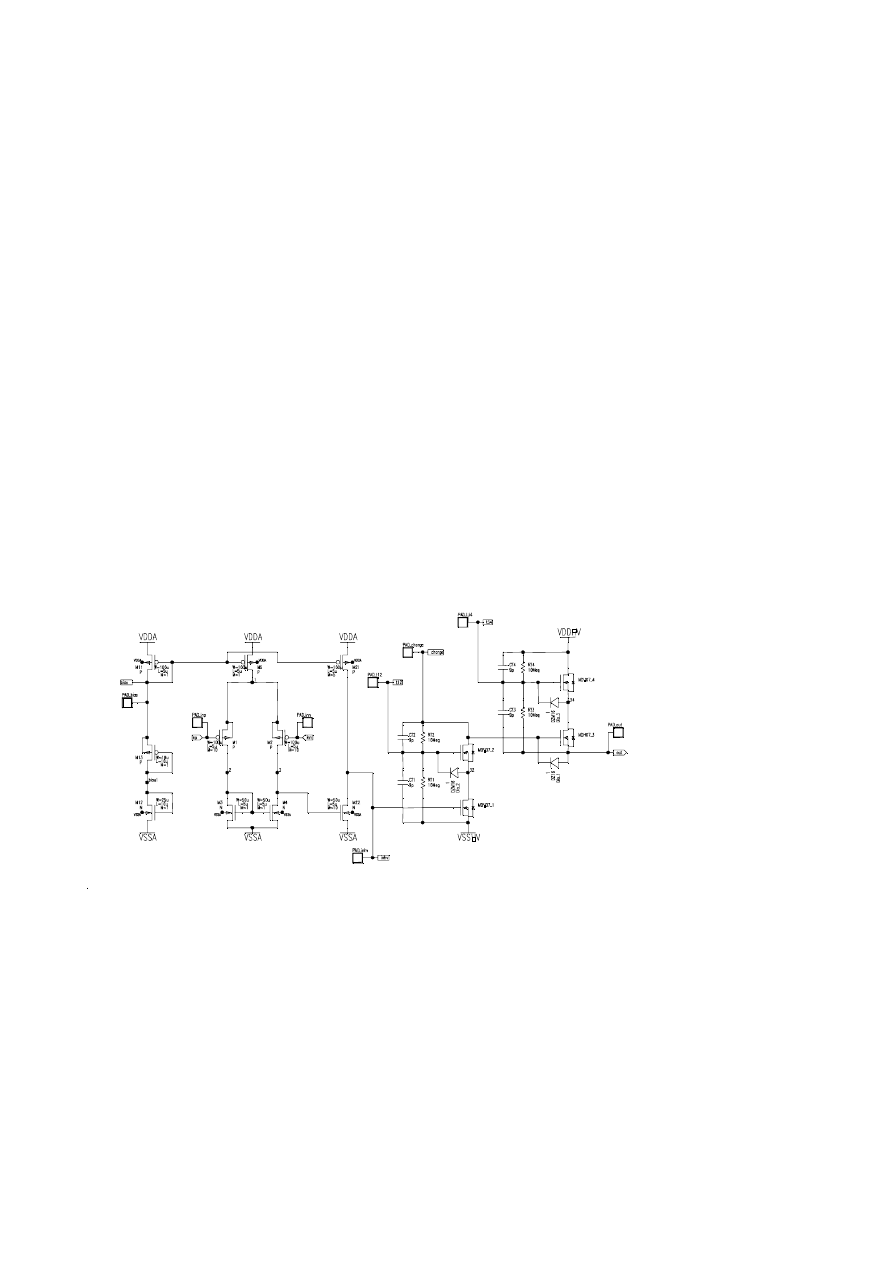
Meyer-type DMOS-capacitances and achieve an average accuracy of 5%. Figure 1 shows the
topology of a linear HV-amplifier to deflect micromechanical scanner mirrors. This design was
derived from a circuit made of discrete components and has been moved to the DMOS process. It
consists of an Miller OTA as preamplifier and a pseudo push-pull output stage. The output
transistors are stacked
to increase the
maximum output
voltage. The
amplifiers gain is
adjusted by an off-
chip feedback network
and the chip area is 4
sqmm in size.
Figure 1: Linear HV-
amplifier circuit
Another example for high-voltage driven microactuators are piezotransducers for ultrasonic mea-
surements. Their utilization in form of phased arrays offers a diversity of possibilities in use. The
control of piezotransducer-arrays used in liquids requires transceiving amplifiers generating short
voltage bursts of several hundred volts with the option to have both polarities. The design of such
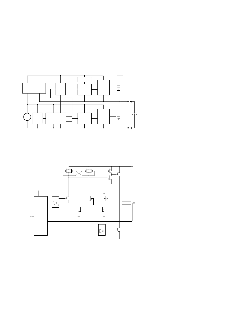
amplifiers has some difficulties to work out. The block diagram of figure 2 shows a complete
integrated half-bridge switching amplifier for unidirectional use. The gate controlled MOS devices
are working in the switch mode to achieve rise / fall times of about 10ns for voltage bursts of 200 V
at a capacitive load of about 10 pF. Beside the gate control of the integrated high voltage output
stage being fast enough there are two main problems to solve for such an application. The first one
is the signal level shift for the high side circuit. The control signal coupled over an isolation stage
from a TTL logic level will be mirrored from the common reference to the high side control level.
The voltage has to be shifted over the distance of the complete output voltage swing. The second
98
problem is the preparation of the high side, output referenced control voltage, originating from the
common referenced control voltage VC.
Some specific problems are referred for example to the fast switching devices (steep transients), the
high at best capacities for bootstrap and charge pump circuits and the wide area consumption of the
high voltage devices (especially for the use of array structures). A feature to increase the usability
of the circuit is an under voltage protection stage availing in the high side control circuit. Therefore
is a monitoring of correct output burst regime superfluous within an measurement application. A
full bridge circuit for the bidirectional control of transducers needed in advanced measurement
methods (coded control, correlation
analysis) has been designed too.
This cannot be solved by simply
doubling the circuit because of the
non-symmetrical DMOS-devices.
Figure 2: Simplified block dia-
gram of a fast half bridge switching
amplifier
In contrast to the linear high voltage amplifier with his advantages a concept of a switch-mode
high-voltage amplifier has been examined. Recently this concept is in the focal point of interest for
several applications. The reason for this interest are the benefits of this concept in context with the
integration. The disadvantage, more expenditure for signal preparation circuits, is compensated
with higher power efficiency and smaller layout area. We use the pulse-width modulation principle
to control the switch mode
amplifier. This employs the
conversion of an analog signal to a
variable-duty-cycle. To drive
micromechanical actuators we use
an output stage with an p-channel
HVMOS- and an n-channel
DMOS-transistor. The first version
of the switch amplifier drives
capacitive loads to a voltage of up
to 300 V.
Figure 3: Class-D-switching-amp-
lifier
In the next evolution steps we plan to achieve voltages up to 600 V and subsequently up to 1000 V.
One of the main problems is signal conditioning for the high side stage. It needs a signal pulse in
reference to the upper voltage rail. We solved this problem with a voltage mirror circuit (figure 3).
This voltage mirror consists of two DMOS-transistors and four PMOS-"standard"-transistors. It
converts the signal with an amplitude of 15 V to 300 V minus 15 V. The high-voltage mirror-circuit
operates like a flip-flop and generates the signal for the p-channel HVMOS-driver. Our future plans
include the integration of some high-voltage amplifiers (4 .. 9 exemplars) with adapted power
supply system and high-voltage generation on one chip.
G ATE
DRIVE
G ATE
DRIVE
CO N TRO L
LO G IC
U V - DETECT
LEVEL
SH IFT
SIG N AL
+H V
C
LO AD
CO N TRO L
LO G IC
SH O O T TRO U G H
PRO TECTIO N
ISO
O U T
Vc
CO M
SH IFT
CO N TRO L VO LTAG E
P_DRV
Vddh
OUT
Filter
XMH1
XMH2
M1
M2
M3
M4
M7
M8
M9
M10
XMH3
XMH11
...
XMH20
N_DRV
P-Channel-DRV
N-Channel-DRV
Vdd
Signal-
Pulse-Width-
Modulation
and
conditioning
IN
Control
Wyszukiwarka
Podobne podstrony:
High voltage electrostatic generator
Make your Own High Voltage Electromagnets
High voltage electrostatic generator
MCP16301 High Voltage Input Integrated Switch Step Down Regulator
15 Electrostatic comb drive X– Y microactuators
dm7407 Hex Buffer Driver with High Voltage Open Collector Outputs
Ir2111 High Voltage High Speed Power Mosfet And Igbt Driver
[DI] Circuit makes simple high voltage inverter
Bearden Tech papers Utilizing Scalar Electromagnetics To Tap Vacuum Energy
Alexander, Lloyd The Chronicles of Prydain 05 The High King 5 0
Lloyd Alexander Chronicles of Prydain 05 The High King
2019 05 26 O Knabit Ideologia gender to kontynuacja komunizmu Do Rzeczy
Alexander, Lloyd Chronicles of Prydain 05 The High King
Alexander, Lloyd Chronicles of Prydain 05 The High King
#0386 – Learning How to Drive
więcej podobnych podstron