Timing belt, checking and adjusting
Removal and Installation
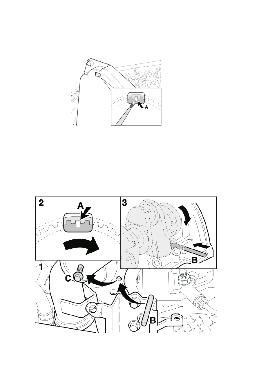
Marking the camshaft pulley
Note! Mark the camshaft pulley to facilitate reading off.
Turn the crankshaft until the marking (A) on the camshaft pulley is visible in the centre of the opening
in the upper timing cover.
Make sure that the marking (A) is clearly visible. Use white paint for example.
Note! It is important to carry out the following when fixing the position of the camshaft.
Remove the plug (C) from the cylinder block (positioned by the fuel filler hose).
Insert the lock pin (B) with an approximate diameter of 8 mm into the opening (do not slide the lock
pin fully into the cylinder block yet).
Turn the crankshaft until the marking (A) on the camshaft pulley is visible in the opening in the timing
cover.
Press the lock pin (B) in the cylinder block towards the crankshaft section. Then turn the crankshaft
until the pin is forced into the groove on the crankshaft (to a depth of 8-10 mm).
The marking on the camshaft pulley must now be approximately in the centre of the groove in the
timing cover.
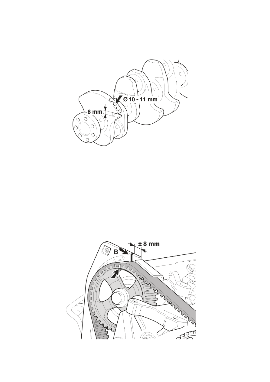
Checking the position of the lock pin
Note! Carried out at top dead centre (TDC).
The groove (zero adjustment of top dead centre) in the crankshaft section is 8 mm wide and 10 mm
deep. When the lock pin has been inserted in the crankshaft section, the crankshaft cannot be turned
any further.
There must not be any play.
Note! If there is play, it may be because the lock pin has been inserted in a balance hole. These holes
have a diameter of 10-11 mm, which would allow the crankshaft to be turned slightly.
Moving the marking
The following must be carried out if the timing belt needs to be removed:
After removing the protective cover, make a permanent mark (B) on the rear timing cover behind the
camshaft pulley. Make a mark on the timing cover which corresponds to the marking on the camshaft
pulley.
Note! The mark (B) must be within ±8 mm, measured from the beginning of the groove in the
crankcase.
Note! The fuel pump (FP) gear does not need to be marked because the injection timing is
electronically regulated.
Moving the marking
The fuel pump (FP) gear does not need to be marked because the injection timing is electronically
regulated.
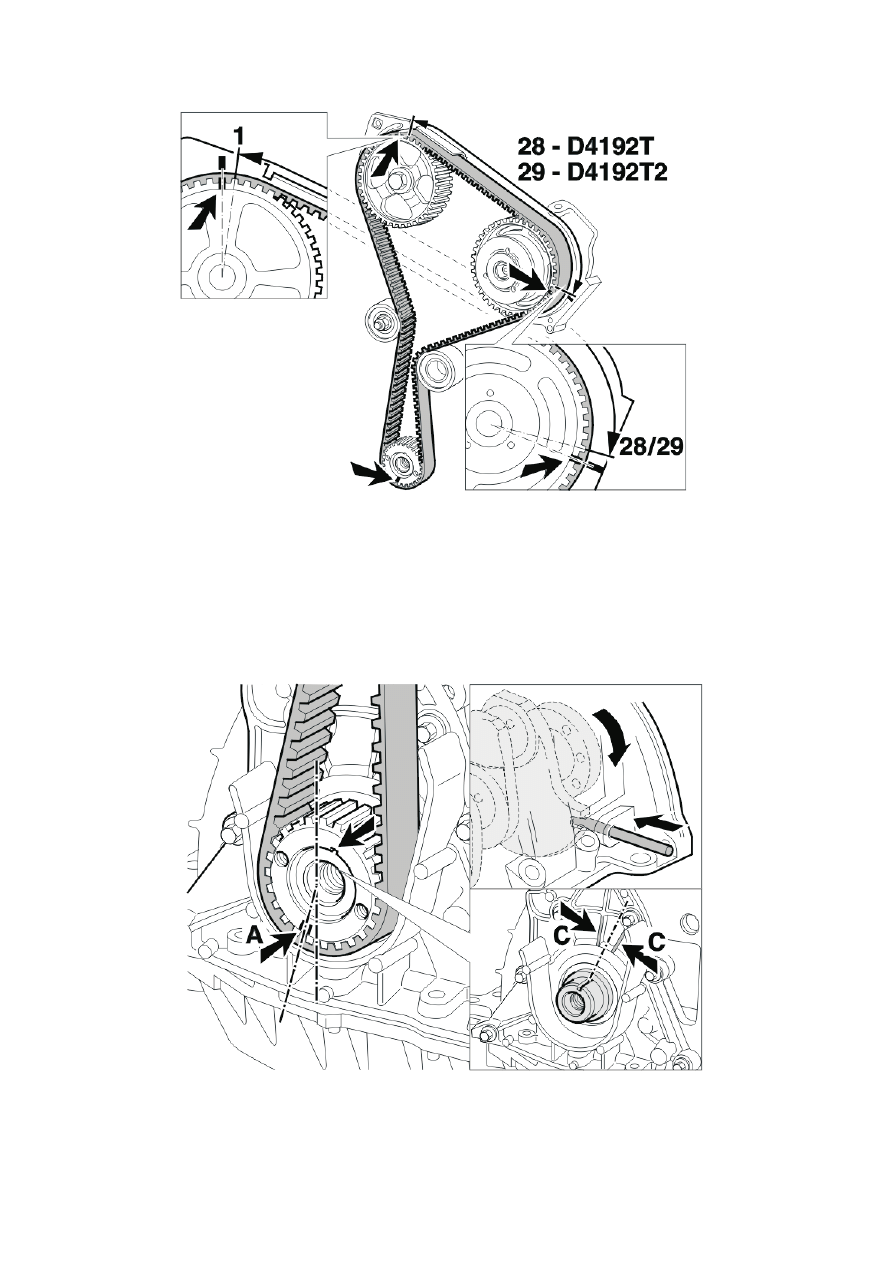
Checking the crankshaft drive gear position (TDC)
When the lock pin has been inserted in the case, the mark (A) on the crankshaft drive gear must be
pointing downwards. (See the illustration).
The crankshaft key must be aligned between the two cast ribs (C) on the front cover. The mark (A) for
the toothed belt is located 1 tooth to the left of the vertical face of the crankshaft, (see the illustration).
Document Outline
Wyszukiwarka
Podobne podstrony:
Wstrząsające znaki na niebie i Ziemi
Znaki na pojazdach
Znaki na stronkę
fragment Znaki na szlaku PL
ZNAKI NA KLAWIATURZE (PICTOGRAMS)
Znaki na towarach
Znaki w sztuce na przykładzie obrazu Małżenstwo Arnolfinich
Uważnie patrzeć na znaki, Z Bogiem, zmień sposób na lepsze; ZAPRASZAM!, katolik. czyli, chomiki w ka
Znaki drogowe obowiązujące na kartę rowerową, KLASA IV
materiay1geodezjagrnicza, Znaki K-1, Podręczny zestaw znaków umownych na mapie zasadniczej wg instru
Znaki umowne na mapie zasadniczej (K 1)
Znaki i napisy na mieczach sredniowiecznych w Polsce
Znaki Zodiaku i ich podziały na części
Uważnie patrzeć na znaki, 3 Stare matriały nieposegregowane
Kirunki świata i znaki patrolowe 08.03.14r, Kospekty na zbiórki harcerskie
bezpieczeństwo na drogach i znaki, różna tematyka
Konspekt dla klasy I(reagowanie na umówione znaki i sygnały)
więcej podobnych podstron