
RA583
Service Manual

TABLE OF CONTENTS
SERVICE WARNING
····································
1
A. I M P O R T A N T S A F E T Y I N S T R U C T I O N
· · · · · · · · · · · · · · · · · · · · ·
1
B. S P E C I F I C A T I O N S
· · · · · · · · · · · · · · · · · · · · · · · · · · · · · · · · · · · · ·
2
C. T I M I N G C H A R T
· · · · · · · · · · · · · · · · · · · · · · · · · · · · · · · · · · · · · ·
3
D. C O N T R O L L O C A T I O N
· · · · · · · · · · · · · · · · · · · · · · · · · · · · · · · · ·
5
E. CONDUCTIONVIEW
···································
6
F. ADJUSTMENTPROCEDURE
···························
·
11
G. T R O U B L E S H O O T I N G H I N T S
· · · · · · · · · · · · · · · · · · · · · · · · · · ·
1 2
H. B L O C K D I A G R A M
· · · · · · · · · · · · · · · · · · · · · · · · · · · · · · · · · · · ·
1 6
I. S C H E M A T I C D I A G R A M
· · · · · · · · · · · · · · · · · · · · · · · · · · · · · · · ·
1 7

WARNING
To prevent from fire or shock hazard,do not expose monitor to any rain or any form of water.High voltage is
inside the monitor so please do not remove the back cover of the cabinet if you are not a qualified
monitor engineer.Contact the local dealer or the nearest Proview branch office if you need help.
A. IMPORTANT SAFETY INSTRUCTION
Prior to using this service manual,please ensure that you have carefully followed all the procedures outlined in
the user's manual for this product.
1. Read all of these instructions.
2. Save these instructions.
3. Follow all warnings and instructions a marked on the product.
4. Unplug this product from the wall outlet before cleaning.Do not use liquid cleaners or aerosol
cleaners, use a damp cloth for cleaning.
5. Do not use this product near water.
6. Do not place this product on an unstable cart,stand or tablle.The product may fall,causing serious
damage to the product.
7. Slots and openings in the cabinet and the back or bottom are provided for ventilation,to ensure
reliable operation of the product and to protect it from overheating,those openings must not be
blocked or covered.The openings should never be blocked by placing the product on a bed,sofa, rug,
or other similar surface.This product should not be placed in a built-in installation less proper
ventilation is provided.
8. This products should be operated from the type of power source indicated on the marketin label.
If you are not sure of the type of power available, consult your dealer or local power company
9. This product is equipped with a 3-wire grounding type plug,a plug having a third (grounding)
pin.This plug will only fit into a grounding-type power outlet.This is a safety feature,if you are
unable to insert the plug into the outlet,contact your electrician to replace your obsolete outlet.Do
not defeat the purpose of the grounding-type plug.
10. Do not allow anything to rest on the power cord.Do not locate this product where persons will walk
on the cord.
11. If an extension cord is used with this product,make sure that the total of the ampere ratings on the
product plugged into the extension cord to the waplugged into outlet does not exceed 15 ampere.
12. Never push objects of any kind into this product through cabinet slots as they may touch dangerous
voltage points or short out parts that could result in a risk of fire or electric shock.Never spill liquid
of any kind on the product.
13. Do not attempt to service this product yourself,as opening or removing covers may expose you to
dangerous voltage points or other risks.Refer all servicing to service personnel.
14. Unplug this product from the wall outlet and refer servicing to qualified service personnel under the
following conditions.
a.
When the power cord or plug is damaged or frayed.
b.
If liquid has been spilled into the product.
c.
If the product has been exposed to rain or water.
d.
If the product does not operate normally,when the operating instructions are followed.Adjust
only those controls that are covered by the operating instructions since improper adjustment of
other controls may result in damage and will often require extension work by a qualified
technician to restore the product to normal operation.
e.
If the product has been dropped or the cabinet has been damaged.
f.
If the product exhibits a distinct change in performance,indicating a need for service.

B. SPECIFICATIONS
1. Maximum Resolution
1024x768 @ 75Hz
2. Recommend Resolution
1024x768 @ 60Hz
3. Synchronization Range
Horizontal
Vertical
30 – 60 KHz
56– 75 Hz
4. Active Display Area
304.1mm (H) x 228.1mm (V)
5. Dot Pitch
0.297(H) x 0.297(V) mm
6. Support display colors
16.7M color
7. Contrast Ratio (Typical)
400:1
8.Luminance of White
250cd/m²
9. Bandwidth
135MHz
10. User Control
4 Key Switch
11. OSD Function
Brightness, Conrast, H-Pos, V-Pos, H. Size, Phase, Color Select,
Auto, Reset, Language, OSD Adjust, Exit
12. View Angle CR=5
Horizontal
Vertical
+-70 Degrees
+-60 Degrees
13. Power Source
90-264Vac 60 / 50 Hz
14. Power Consumption
48W (max.)
15. Connection Type
15 Pin D Type
16. Input Signal
Video
Sync.
Analog R.G.B. , 0.7Vp-p / 75 Ohms
TTL level,positive or negative polarity
17. Color Temperature
Cool / Warm
18. Dimension (WxHxD)
421mm x 418mm x 188mm
19. Monitor Weight
4.8Kg
20. Base Operation
Tilt
0 / + 15 degree
21. Power Saving
ON
STAND BY
OFF
<
30W
<
3W
<
3W
22. Signal Connector Pin Assignment
Pin No.
1. Red 9. V
DD
from PC for DDC
2. Green 10. Sync. Ground
3. Blue 11. Ground
4. Ground 12. SDA (For DDC)
5. Self Test 13. Horizontal Sync.
6. Red Ground 14. Vertical Sync.
7. Green Ground 15. SCL (For DDC)
8. Blue Ground
23. Audio signal
3.5Φ stereo phone jack
Input Sensitivity : 200mV
2.5+2.5W 8Ω Speaker
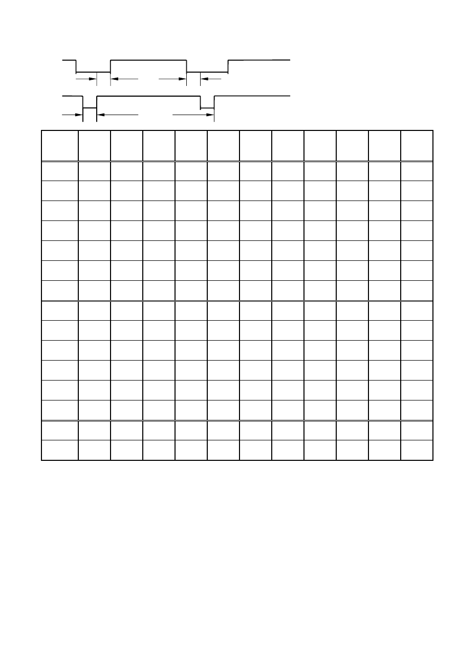
C.TIMING CHART
Video A: Period
D B E B: Active
C: Sync Width
Sync. D: Back Porch
C A E: Front porch
Preset
Modes
VGA
640X350
VGA
640X400
VGA
640X480
VGA
640X480
VESA
640X480
VESA
640X480
VGA
720X350
VGA
720X400
VESA
800X600
VESA
800X600
VESA
800X600
Dot Rate
25.175MHz 25.175MHz 25.175MHz
31.340MHz
31.500MHz 31.500MHz
28.322MHz
28.322MHz 36.000MHz 40.000MHz 50.000MHz
F.H
31.469KHz 31.469KHz 31.469KHz
34.978KHz
37.861KHz 37.500KHz
31.469KHz
31.469KHz 35.156KHz 37.879KHz 48.077KHz
A-period
31.778us 31.778us
31.778us
28.590us
26.413us
26.667us
31.777us
31.777us 28.444us 26.400us
20.800us
B-Active
25.422us 25.422us
25.422us
20.421us
20.317us
20.317us
25.422us
25.422us 22.222us 20.000us
16.000us
C-Syn
3.813us
3.813us
3.813us
2.042us
1.270us
2.032us
3.813us
3.813us
2.000us
3.200us
2.400us
D-Back
Porch
1.907us
1.907us
1.589us
3.063us
3.810us
3.810us
1.907us
1.907us
3.556us
2.200us
1.280us
E-Front
Porch
0.636us
0.636us
0.954us
3.064us
1.016us
0.508us
0.635us
0.635us
0.666us
1us
1.12us
F . V
70.087Hz 70.087Hz
59.941Hz
66.625Hz
72.810Hz
75.000Hz
70.087Hz
70.087Hz 56.250Hz 60.317Hz
72.188Hz
A-Period
14.268ms 14.268ms
16.683ms
15.009ms
13.734ms
13.333ms
14.268ms
14.268ms 17.778ms 16.579ms
13.853ms
B-Active
11.122ms 12.711ms
15.253ms
13.723ms
12.678ms
12.800ms
11.122ms
12.711ms 17.067ms 15.840ms
12.480ms
C-Syn
0.064ms
0.064ms
0.064ms
0.086ms
0.079ms
0.080ms
0.064ms
0.064ms
0.057ms
0.106ms
0.125ms
D-Back
Porch
1.907ms
1.112ms
0.794ms
1.115ms
0.528ms
0.427ms
1.907ms
1.112ms
0.626ms
0.607ms
0.478ms
E-Front
Porch
1.175ms
0.381ms
0.572ms
0.085ms
0.449ms
0.026ms
1.175ms
0.381ms
0.028ms
0.026ms
0.77ms
H/V
SYNC
+ -
- +
- -
- -
- -
- -
+ -
- +
+ +
+ +
+ +
Interlace
NON
NON
NON
NON
NON
NON
NON
NON
NON
NON
NON

Preset
Modes
VESA
800X600
MAC
832X624
VESA
1024X768
VESA
1024X768
VESA
1024X768
Dot Rate
49.500MHz
55.000MHz
65.000MHz 75.000MHz 78.750MHz
F.H
46.875KHz
49.107KHz
48.363KHz 56.476KHz 60.023KHz
A-period
21.333us
20.364us
20.677us 17.707us
16.660us
B-Active
16.162us
15.127us
15.754us 13.653us
13.003us
C-Syn
1.616us
2.182us
2.092us
1.813us
1.219us
D-Back
Porch
3.232us
1.745us
2.462us
1.920us
2.235us
E-Front
Porch
0.323us
1.31us
0.369us
0.321us
0.203us
F . V
75.000Hz
75.087Hz
60.004Hz 70.069Hz
75.029Hz
A-Period
13.333ms
13.318ms
16.666ms 14.272ms
13.328ms
B-Active
12.800ms
12.707ms
15.880ms 13.599ms
12.795ms
C-Syn
0.064ms
0.061ms
0.124ms
0.106ms
0.050ms
D-Back
Porch
0.448ms
0.428ms
0.600ms
0.513ms
0.466ms
E-Front
Porch
0.021ms
0.122ms
0.062ms
0.054ms
0.017ms
H/V
SYNC
+ +
- -
- -
- -
+ +
Interlaced
NON
NON
NON
NON
NON
D. CONTROL LOCATION
Font control panel
1.
Power Button
2.
2. LED (Power Display)
3. Menu Button
4. Select Button
5. Auto Button
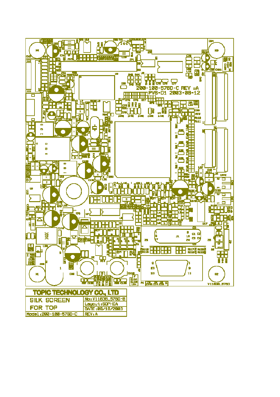
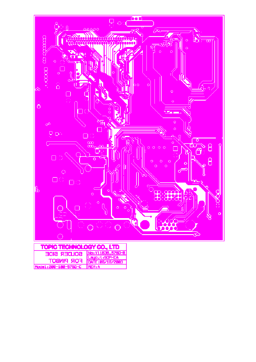
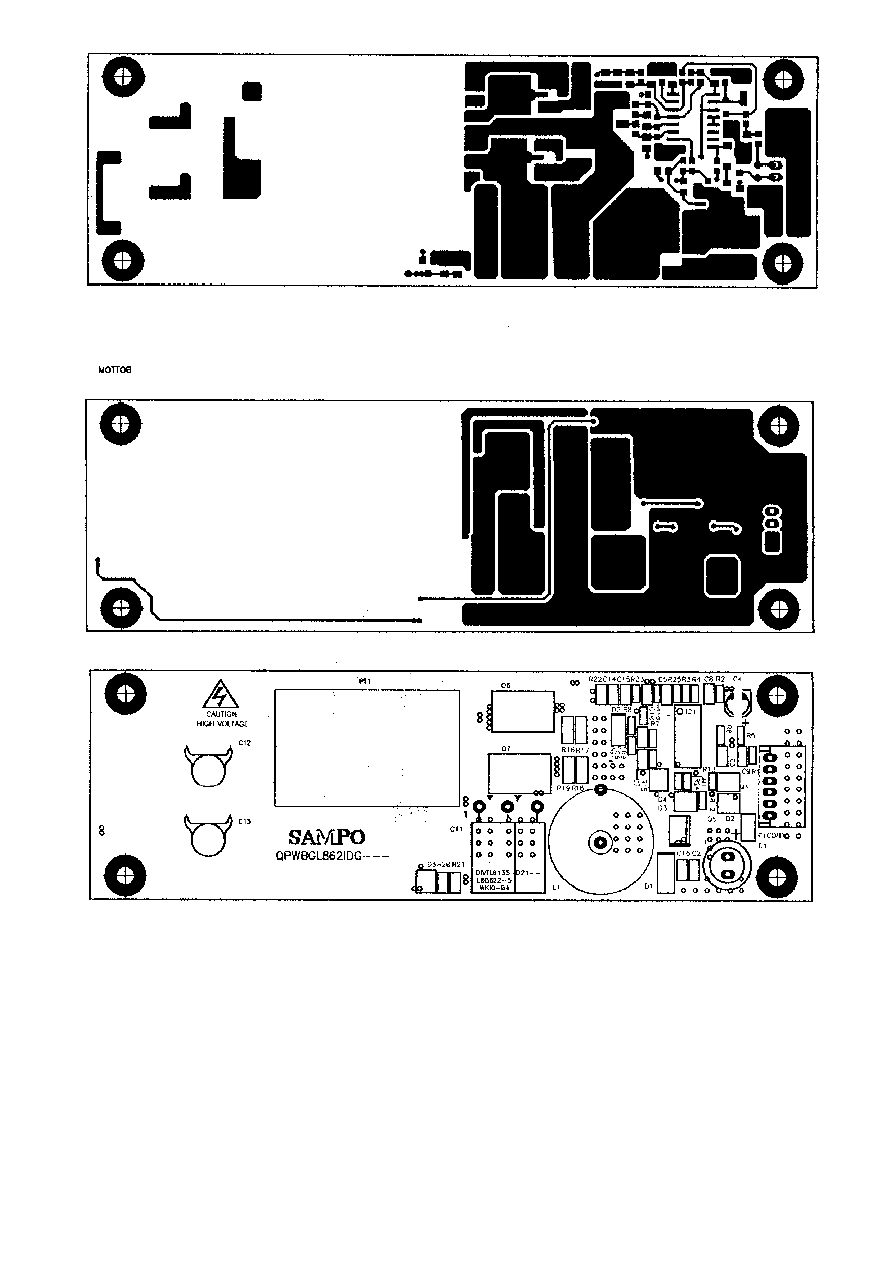
E. CONDUCTION VIEW
MAINBOARD(ComponentSide)

MAIN BOARD (Component Side)
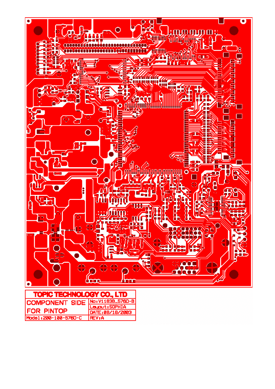
MAIN BOARD (Solid Side)
F. ADJUSTMENT PROCEDURE
ITEM
Program Menu.
﹟Test Meter
﹡Test Point
﹫Pattern
Operation
Check
Value
A
B+
Check
﹟Digital Voltmeter
﹡CN7
﹫Crosshatch Pattern
(31.5KHz,640x480)
1. Plug power cable into the adapter, check adapter
power indicator light up green.
2. Make sure the voltage of the power plug (
CN7
)
on the main
PCB
to the value shown at right.
12.0V
±0.2V
B
Power Saving
Check
﹟Wattmeter
﹟PC or Pattern
generator
﹫Crosshatch Pattern
(31.5KHz,640x480)
1. Unplug the signal cable into the monitor.
2. Turn the power switch of the monitor
ON
.
3. Check monitor power indicator light up orange.
4. Make sure the wattmeter value shown at right.
5.
OSD
will be display “
NO SIGNAL
” Picture.
‹ 2.5W
C
Into Factory
mode
﹟PC or Pattern
generator
﹫Crosshatch Pattern
(31.5KHz,640x480)
1. Hold ‹ key,then turn the power switch of the
monitor
OFF
.
2. Hold › key,then turn the power switch of the
monitor
ON
.
3. You can into factory adjustment mode.
D
Auto mode
Check
﹟PC or Pattern
generator
﹫Crosshatch Pattern
(1024x768/60Hz)
1. Press and relese the
MENU
knob to activate the
OSD
menu.
2. Move the
OSD
to the
AUTO
function,press
MENU
key auto adjuat display mode to its utmost
performance according to
VGA
setting.
3. In the event of the display image needs further
adjustment
E
White
Balance
Adjust
﹟
PC or Pattern
generator
﹫White Pattern
(1024x768/60Hz)
1. Move the
OSD
to the
COLOR mode
(
AUTO COLOR).
2. set color is 9300
°K
using the
OSD
,Check the value
shown at right.
Y = 220±0.1FL x = 0.283±0.01 y = 0.297±0.01
3. set color is 6500
°K
using the
OSD
,Check the value
shown at right.
Y = 220±0.1FL x = 0.313±0.01 y = 0.329±0.01
F
OSD
Language
Setting
﹟
PC or Pattern
generator
1. Move the
OSD
to the
LANGUAGE mode
.
2. You can choose one of the eight language you need.
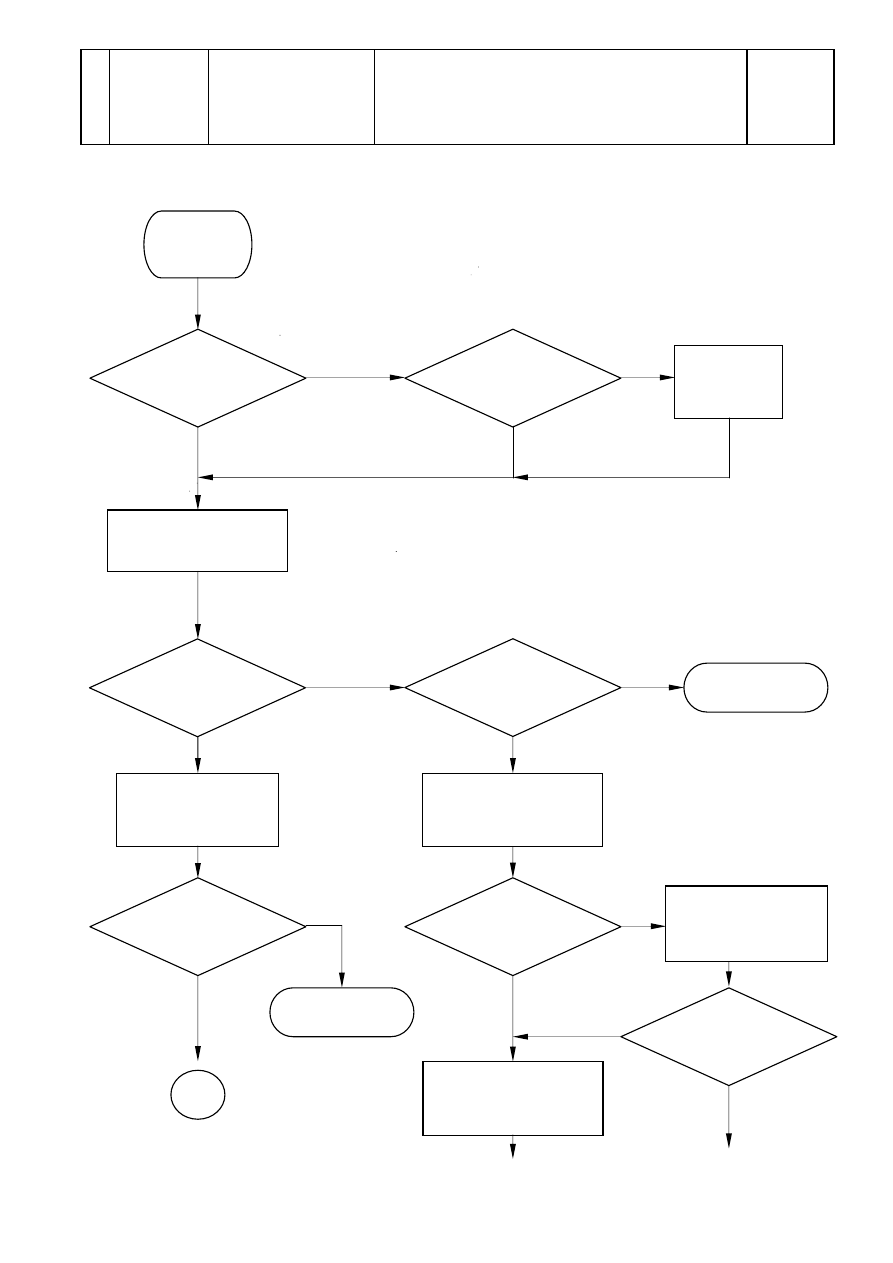
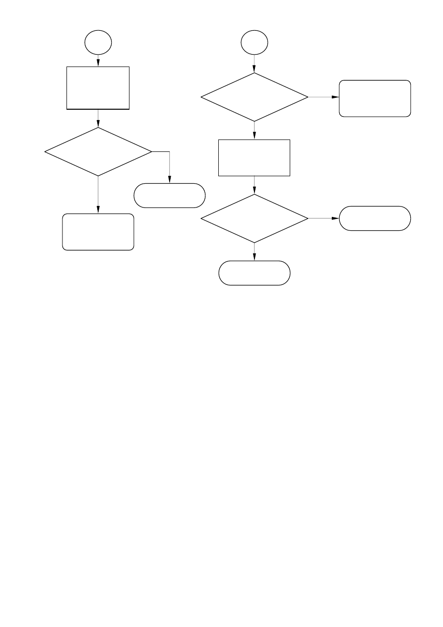
G. TROUBLE SHOOTING HINTS
NO NO
YES YES
YES
YES
NO
NO
High Voltage !
NO
YES
YES
NO
NO
YES
No Display
( Black )
LED ON
?
Push the power
ON/OFF
switch
LED Color
change ?
Check main
board U2/Pin2
Hi / Lo under
push power
sw?
Back light
ON?
To Step 2
Make sure the
connection of
Inverter is fine
+12V ?
Check the
CN1
/Pin1
of Inverter
Check
F1(Fuse) of inverter
Display ?
A
To Step 2
Power
adapter ?
Change
adapter

B
Nice Job !
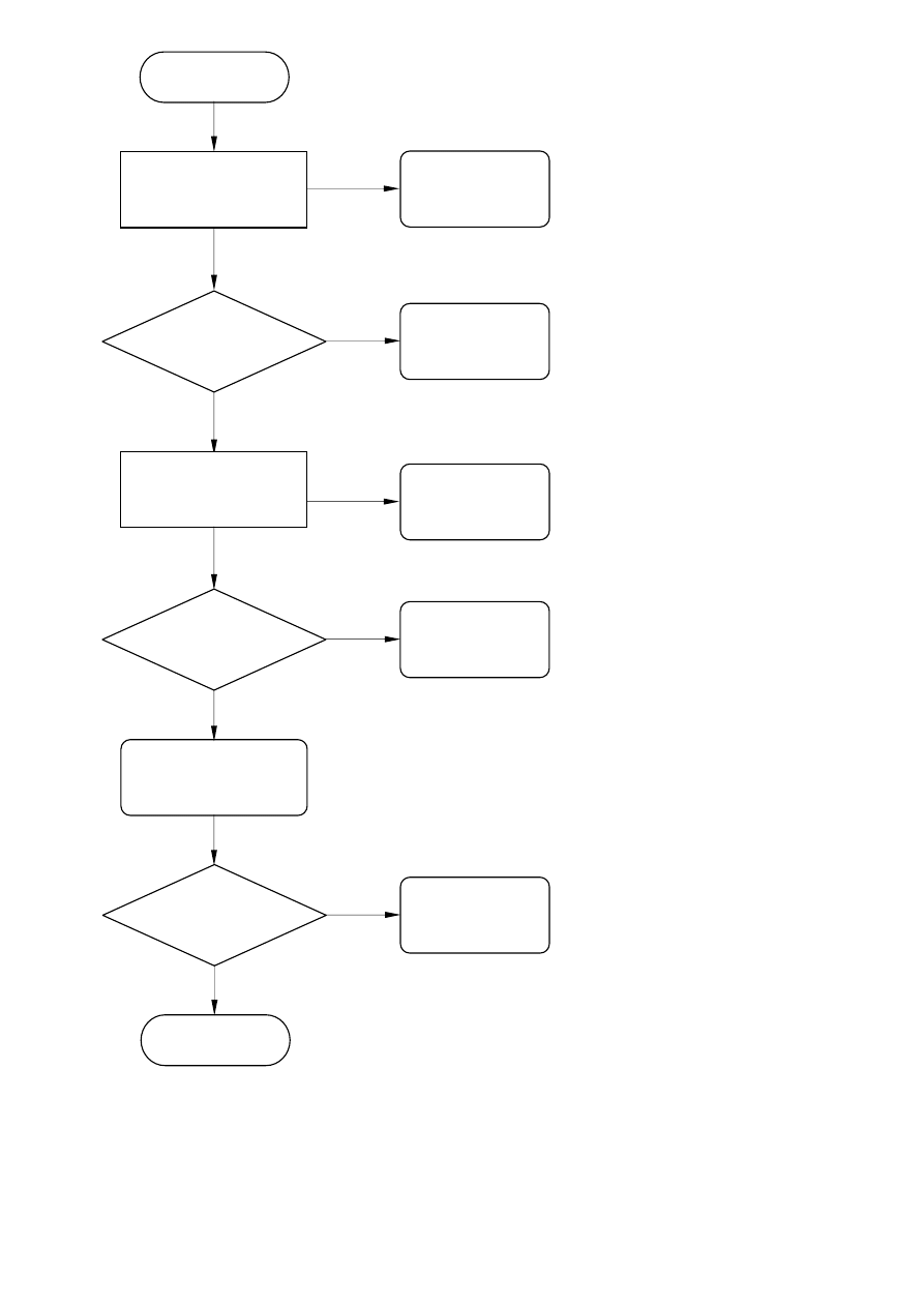
NO
YES
YES
NO
YES
NO
B
Hi / Lo under
push power
sw?
Change the
Inverter
Display ?
Nice Job !
To Step 2
A
Check the
connection of
CN8
cable
Display ?
Nice Job !
Change the
main board
Change the
main board
NO
YES
NO
YES
YES
YES
YES
NO
NO
YES
Step 2
Check the main
board
12V
?
+5.0 V ?
Check
U10,U11,TR1
H/V input
Signal ?
Check the main
board
U7
/
Pin 5
?
Change
U9
Check
H/V Signal
Display ?
Nice Job !
Change
Signal Cable
Check
F1,D5
Check
U7
NO
YES
NO
YES
NO
YES
YES
NO
NO
YES
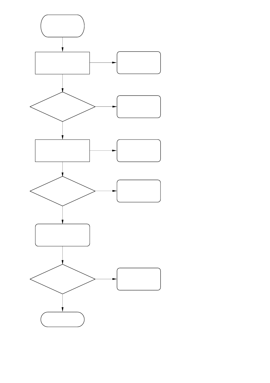
.
No display
(White)
Check the main
board
5V
?
+3.3V ?
H/V Input
Signal ?
Check the main
board
U9/Pin3
?
Change
U9
Check
H/V Signal
Display ?
Nice Job !
Change
Signal Cable
Check
U10,U11,TR1
Check
U8,U13
Check
3.3V Circuit

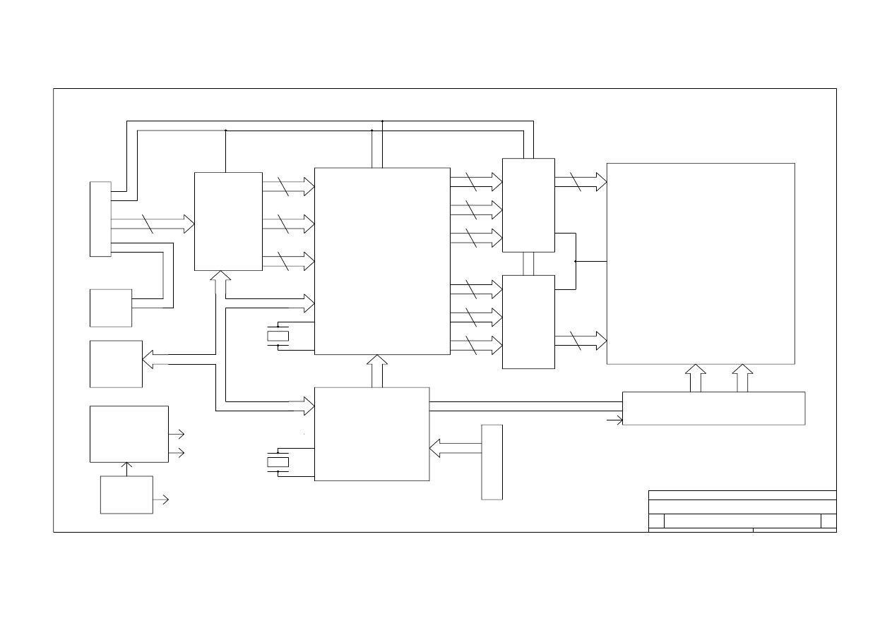
H. BLOCK DIAGRAM
ORION
B
BLOCK DIAGRAM
B
1
1
Tuesday, October 23, 2001
Title
Size
Document Number
Rev
Date:
Sheet
of
HSYNC
VSYNC
D-DE
BLK-ON/OFF
SDA
BRIGHTNESS
DDC-SCL
DDC-SDA
SCL
POWER
ADAPTER
12V
SWITCH POWER
SUPPLY AND
3V
5V
12V
C
O
N
N
E
N
T
VGA-IN
12PIN
D.D.C
24C21
EEPROM
ADC
SCALER
LVDS
LVDS
MCU
24C16
EEPROM
INVERTER
12V
C
O
N
N
E
N
T
FUNCTION KEY
8PIN
LCD PANEL(LVDS)
REGULATOR
CRYSTAL
CRYSTAL
3 {R.G.B}
12M HZ
12M HZ
8 R0~R7
8 G0~G7
8 B0~B7
8 RA0~RA7
8 GA0~GA7
8 BA0~BA7
8 RB0~RB7
8 GB0~GB7
8 BB0~BB7
10 ODD
10 EVEN
POWER
HI VOLTAGE

I.SCHEMATIC DIAGRA
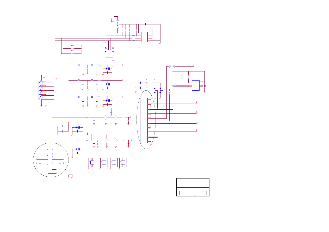
200-100-576D (PV6-D1)
S3
VGA/DVI INPUT
Proview Electronics (Taiwan) Co., LTD.
6F, NO.1, Pau-Sheng Rd., Yung-Ho City,
Taipei County, Taiwan R.O.C.
Tel: 886-2-2231-6789 Fax: 886-2-2232-4613
1
6
Friday, December 13, 2002
Title
Size
Document Number
Rev
Date:
Sheet
of
VE
VE
VCC
VE
VE
VE
VE
VE
VE
VCC
VE
VE
VE
VE
VE
VCC
VCC
VCC
BAIN
2
GAIN
2
RAIN
2
AHSYNC
2
RXD_PC
TXD_PC
RX2m
2
RX2p
2
RX1m
2
RX1p
2
RX0m
2
RX0p
2
RXCm
2
RXCp
2
AVSYNC
2
RXD_PC
TXD_PC
RXD_PC
TXD_PC
TXD
2
RXD
2
232E
2
232E
2
R
G
B
VCK_D1
P5V_D1
SDA_D1
SCL_D1
HPDET_D1
PIN9
DDC-SDA
DDC-SCL
VGA_HSYNC
VGA_VSYNC
VGA_VSYNC
R
G
B
VGA_HSYNC
VGA_VSYNC
DDC-SDA
VGA_HSYNC
VGA_VSYNC
PIN9
B
G
DDC-SCL
R
GND
R3
47K
D9
DAN217K(NP)
A
C
AC
H2
TP
1 2 3
4
5
6
7
8
9
1 2 3
4
5 6
7
8
9
L2
0R
1
2
L4
0R
1
2
C6
5PF
Q6
2N3904
B
E
C
Q7
2N3904
B
E
C
D4
DAN202K/NC
A2
C
A1
R51
4.7K(NP)
L6
0R
1
2
R50
4.7K
R54
4.7K
R1
47K
R55
4.7K
D1
DAN202K/NC
A2
C
A1
C16 0.1uF(NP)
P1
DB15HD
1
2
3
4
5
6
7
8
9
10
11
12
13
14
15
16
17
D10
DAN217K(NP)
A
C
AC
R18 51R
R17 51R
C20 0.1uF(NP)
R13
47K
D11
DAN217K(NP)
A
C
AC
R14
47K
R15
10K(NP)
R59
0(NC)
R62
0(NC)
R21
10K/NC
C3
5PF
C7
5PF
C10
5PF
C5
0.1uF
D7
DAN217K(NP)
A
C
AC
R7
0R
R5
0R
C148
0.1uF
C147
0.1uF
D6
DAN217K(NP)
A
C
AC
U3B
74LVC14-SOP14
3
4
14
7
U2
24LC21A
1
2
3
4
5
6
7
8
NC1
NC2
NC3
GND
SDA
SCL
VCLK
VCC
J1
DVI_D_CON/NC
1
2
3
4
5
6
7
8
9
10
11
12
13
14
15
16
17
18
19
20
21
22
23
24
25
26
C1
C2
C3
C4
C5
DATA2-
DATA2+
DATA2/4_SHLD
DATA4-
DATA4+
DDC_CLK
DDC_DATA
A_VSYNC
DATA1-
DATA1+
DATA1/3_SHLD
DATA3-
DATA3+
+5V
GND
H_PLUG_DET
DATA0-
DATA0+
DATA0/5_SHLD
DATA5-
DATA5+
CLK_SHLD
CLK+
CLK-
SHELL1
SHELL2
A_RED
A_GREEN
A_BLUE
A_HSYNC
A_GND
C17
NC
R28
NC
U3D
74LVC14-SOP14
9
8
14
7
U3C
74LVC14-SOP14
5
6
14
7
H3
TP
1 2 3
4
5
6
7
8
9
1 2 3
4
5 6
7
8
9
U1
24LC21
1
2
3
4
5
6
7
8
NC
NC
NC
VSS
SI
SCK
VCLK
VCC
C21
0.1uF
C1
0.1uF
D5
DAN217K(NP)
A
C
AC
R20
75
R4
47K
U3A
74LVC14-SOP14
1
2
14
7
R6
NP
R23
75
C4
0.1uF(NP)
C12
22pF
H4
TP
1 2 3
4
5
6
7
8
9
1 2 3
4
5 6
7
8
9
C11 0.1uF(NP)
D3
DAN217K(NP)
A
C
AC
R9
51
R16
75
L3
0R
1
2
R11
BE0603
D8
DAN217K(NP)
A
C
AC
R24
100
R8
51
R26
100
L5
0R
1
2
R12
47R
R25
100
C2
5PF
H1
TP
1 2 3
4
5
6
7
8
9
1 2 3
4
5 6
7
8
9
C9
5PF
C14
0.1uF
R27
100
D2
DAN217K(NP)
A
C
AC
C18
22pF
R19
47R
C8
0.1uF(NP)
R2
(NP)
R22
47R
C15
0.1uF
L1
0R
1
2
C13
22pF
C19
22pF
Check DVI package
200-100-576D (PV6-D1)
S3
A/D + Scaler
Proview Electronics (Taiwan) Co., LTD.
6F, NO.1, Pau-Sheng Rd., Yung-Ho City,
Taipei County, Taiwan R.O.C.
Tel: 886-2-2231-6789 Fax: 886-2-2232-4613
2
6
Friday, December 13, 2002
Title
Size
Document Number
Rev
Date:
Sheet
of
V18A
V18
V33
V33
3.3VDVI
3.3VADC
V18
V33
V33
3.3VADC
V33
3.3VDVI
PV1
V18
V33
V18
V33
V18
PV1
V33
3.3VADC
3.3VADC
V33
V33
V18
V18
3.3VADC
V33
V33
3.3VDVI
3.3VADC
VCC
VE
V33
AVSYNC
1
AHSYNC
1
GAIN
1
BAIN
1
RAIN
1
RX2p
1
RX2m
1
RX0m
1
RX0p
1
RX1m
1
RX1p
1
RXCm
1
RXCp
1
LED1
3
LED2
3
RESETn
3
LVDSON
4
MUTE
6
BKLON
5
LCDON
4
SCL
3
SDA
3
PWMOUT
5
NMI
3
A[19:1]
3
D[15:0]
3
ROMWEn
3
CS0n
3
RDn
3
ROMOEn
3
DCLK
4
DVS
4
DHS
4
DEN
4
DRE[7:0]
4
DGE[7:0]
4
DBE[7:0]
4
DRO[7:0]
4
DGO[7:0]
4
DBO[7:0]
4
DPMS
5
RXD
1
TXD
1
VOLUME
6
232E
1
DGO2
DBO5
DV
1
D1
IGREEN
DRE6
D2
DBO6
D11
TESTEN
DGO4
A14
DRO0
D0
DGE6
DGE0
DBO3
D13
A3
ISOG
DBE5
LV1
DRO5
A12
D6
DRO7
R28C11
DRO3
A7
DBO0
A13
A16
IRED
DBE7
DRE0
D15
D14
DRO6
A6
MPV1
D
PV1
A8
DRO2
A9
DBE3
DGO1
D3
DGE1
A18
DGE7
DGO0
A15
RTERM
DRO4
A1
GFILT
D8
DBO1
DGE3
D12
DRE7
A5
DRO1
DGO6
DGO3
DGO7
A17
D4
DBO2
DGE5
X608
DBE6
D5
DGE2
D7
DGO5
DRE1
A19
DRE3
DRE2
DBO4
DBE0
X607
D10
A2
DRE5
DGE4
IBLUE
DBE4
DRE4
A10
A4
DBO7
DBE2
A11
DBE1
D9
C74
NC
R65
0R
R66
0R
PW131
Misc
U4C
PW13x
193
192
191
190
189
188
183
182
181
180
179
178
177
176
175
164
163
162
161
160
159
158
157
156
155
154
153
152
151
150
149
148
145
144
143
196
195
197
198
199
200
137
132
53
54
208
207
206
205
204
203
202
201
142
141
140
139
138
194
169
170
A1
A2
A3
A4
A5
A6
A7
A8
A9
A10
A11
A12
A13
A14
A15
A16
A17
A18
A19
D0
D1
D2
D3
D4
D5
D6
D7
D8
D9
D10
D11
D12
D13
D14
D15
RD
WR
ROMOE
ROMWE
CS0
CS1
TESTEN
RESETB
RXD
TXD
PORTA0
PORTA1
PORTA2
PORTA3
PORTA4
PORTA5
PORTA6
PORTA7
TRST
TCK
TMS
TDI
TDO
NMI
XI
XO
R35
3.3K
C51
0.1uF
C52
0.1uF
L10
22uH
R33
NP
L9
22uH
C45
0.1uF
C24
47nF
R29
100(NC)
C29
18pF
C53
0.1uF
C41
0.1uF
C25
47nF
C50
0.1uF
R84
NC
R88
NC
C72
NC
C73
NC
C49
0.1uF
R34
3.3K
Y1
XTAL14.31818
C30
0.1uF
C46
0.1uF
C54
0.1uF
R36
430
C31
0.1uF
C34
0.1uF
R106
NC
R64
4.7K
C23
39nF
C47
0.1uF
R37
1.5M
C28
18pF
C57
0.1uF
R30
3.3K
WRN1
C26
1nF
L11
22uH
C56
0.1uF
Display Port
U4B
PW13x
106
107
101
102
103
98
97
94
93
92
91
90
89
88
87
86
85
82
81
80
79
78
77
74
73
71
70
67
66
131
130
129
128
127
126
125
124
121
120
119
118
117
116
115
114
113
112
111
110
109
108
100
99
DCLK
DCLKNEG
DVS
DHS
DEN
DR0
DR1
DR2
DR3
DR4
DR5
DR6
DR7
DG0
DG1
DG2
DG3
DG4
DG5
DG6
DG7
DB0
DB1
DB2
DB3
DB4
DB5
DB6
DB7
DGR0
DGR1
DGR2
DGR3
DGR4
DGR5
DGR6
DGR7
DGG0
DGG1
DGG2
DGG3
DGG4
DGG5
DGG6
DGG7
DGB0
DGB1
DGB2
DGB3
DGB4
DGB5
DGB6
DGB7
C33
0.1uF
CS1N1
L7
22uH
C38
0.1uF
C39
0.1uF
R32
(NP)
C27
47nF
C35
0.1uF
C32
0.1uF
C37
0.1uF
C36
0.1uF
R31
0R
C40
0.1uF
C48
0.1uF
U8
P2781A(NP)
1
2
3
4
5
6
7
8
XIN
XOUT
FS1
LF
VSS
MOUT
RS0
VDD
J8
CON4
1
2
3
4
R113
NC
Power and Ground
U4D
PW13x
1 3 20
2 4 19
6 18
9 12 15
22 24 26
21 25 27
28 29
30 31
32 33 36 39 41 46 48 52
34 35 38 40 42 45 47 49 51
68 83 104 122 133 171 186
69 84 105 123 134 172 187
75 95 135 146 173 184
76 96 136 147 174 185
165
167
166
168
DV
DD11
DV
DD12
DV
DD13
DGND11 DGND12 DGND13
DV
DD31
DV
DD32
DGND31 DGND32 DGND33
PVD
11
PVD
12
PVD
13
PG
ND11
PG
ND12
PG
ND13
AL
VD
D
11
AL
VD
D
12
AL
GND11
AL
GND12
AV
DD31
AV
DD32
AV
DD33
AV
DD34
AV
DD35
AV
DD36
AV
DD37
AV
DD38
AG
ND31
AG
ND32
AG
ND33
AG
ND34
AG
ND35
AG
ND36
AG
ND37
AG
ND38
AG
ND39
VDDQ31 VDDQ32 VDDQ33 VDDQ34 VDDQ35 VDDQ36 VDDQ37
VSSQ
31
VSSQ
32
VSSQ
33
VSSQ
34
VSSQ
35
VSSQ
36
VSSQ
37
VDD11 VDD12 VDD13 VDD14 VDD15 VDD16
VSS1
1
VSS1
2
VSS1
3
VSS1
4
VSS1
5
VSS1
6
DP
LLV
DD1
M
PLLV
DD1
D
PL
LVSS1
MPL
LVSS1
C22
3.9nF
U3E
74LVC14-SOP14
11
10
14
7
L8
22uH
C55
0.1uF
Graphics and
Video Port
U4A
PW13x
63
62
61
60
59
58
57
56
55
64
65
72
17
16
14
13
11
10
8
7
5
50
44
43
37
23
V656_0
V656_1
V656_2
V656_3
V656_4
V656_5
V656_6
V656_7
VPEN
VS
HS
VCLK
RCM
RCP
RX0M
RX0P
RX1M
RX1P
RX2M
RX2P
RTERM
BLUE
SOG
GREEN
RED
FILTER
C44
0.1uF
C42
0.1uF
350ma max.
175ma max.
Sleep Mode 9ma max.
40ma max.
Sleep Mode 35ma
90ma max.
40ma max.
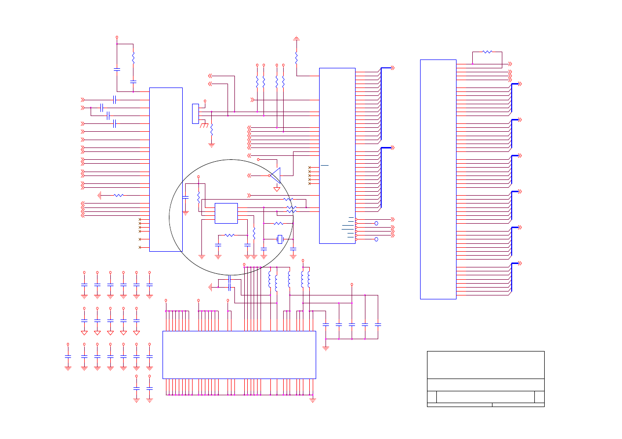
200-100-576D (PV6-D1)
S3
MEMORY & LCD POWER CONTROL
Proview Electronics (Taiwan) Co., LTD.
6F, NO.1, Pau-Sheng Rd., Yung-Ho City,
Taipei County, Taiwan R.O.C.
Tel: 886-2-2231-6789 Fax: 886-2-2232-4613
3
6
Friday, December 13, 2002
Title
Size
Document Number
Rev
Date:
Sheet
of
V33
V33
V33
V33
V33
V33
V33
V33
V33
V33
V33
V33
V33
V33
V33
V33
V33
V33
V33
V33
RDn
2
CS0n
2
NMI
2
SDA
2
SCL
2
ROMOEn
2
ROMWEn
2
RESETn
2
A[19:1]
2
D[15:0]
2
D[15:0]
2
LED2
2
LED1
2
ROMWEn
FCEn
A8
A14
A1
A10
NMI
A12
A3
A13
A17
A9
A1
A11
A4
A7
A4
ICEn
A15
IRPn
IA21
A9
A6
IA20
A3
ICEn
ROMOEn
A15
A16
A8
A19
FCEn
U3C5
A2
U3WPn
A18
A6
A13
A19
A5
A18
A17
A11
A14
A12
A5
A16
A7
A2
RESETn
A10
NMI
LEFT
POWER
MENU
RIGHT
RESETn
D4
D8
D3
D5
D14
D9
D11
D14
D2
D15
D10
D1
D7
D15
D5
D4
D3
D6
D12
D5
D0
D[15:0]
D7
D9
D12
D6
D6
D1
D8
D1
D2
D10
D11
D4
D3
D7
D2
D13
D13
D0
D0
RIGHT
LEFT
MENU
POWER
LED_O
AUTO
AUTO
LED_G
C61
NC
1
2
R10
0R
R57
3.3K
R63
2.2K
R60
3.3K
R39
10K
R42
10K
R41
10K
R40
10K
R43
10K
R56
10K
C69
0.1uF
C60
0.1uF
U7
24C16
5
6
8
4
1
2
3
7
SDA
SCL
VCC
GND
NC0
NC1
NC2
WP
JP1
HDR_RA30X2
1
2
3
4
5
6
7
8
9
10
11
12
13
14
15
16
17
18
19
20
21
22
23
24
25
26
27
28
29
30
31
32
33
34
35
36
37
38
39
40
41
42
43
44
45
46
47
48
49
50
51
53
55
57
59
52
54
56
58
60
R58
3.3K
U5
EN29LV800T-90
37
13
46
27
29
30
31
32
33
34
35
36
38
39
40
41
42
43
44
45
1
2
3
4
5
6
7
8
17
18
19
20
21
22
23
24
25
48
26
28
11
12
14
47
16
VCC
VPP
GND1
GND2
D1
D9
D2
D10
D3
D11
D4
D12
D5
D13
D6
D14
D7
D15
D8
D16
A15
A14
A13
A12
A11
A10
A9
A8
A17
A7
A6
A5
A4
A3
A2
A1
A0
A16
CE
OE
WE
RP
WP
BYTE
A18
R48
100K
J12
CON3
1
2
3
R61
3.3K
C59
0.1uF
R49
100K
CN2
WAFE-8PIN-1.5MM-90@
1
2
3
4
5
6
7
8
9
R53
33R
C63
0.1uF
C65
0.1uF
R52
33R
C64
0.1uF
C62
0.1uF
R47 2.2K
RP4
33X4
1
8
2
7
3
6
4
5
C68
0.1uF
C67
0.1uF
C66
0.1uF
R38
100K
R44
10K
R45
10K
R46
10K
U6
74LVC541A
2
3
4
5
6
7
8
9
10
20
19
1
18
17
16
15
14
13
12
11
I0
I1
I2
I3
I4
I5
I6
I7
GND
VCC
OE2
OE1
O0
O1
O2
O3
O4
O5
O6
O7
J11
CON4
1
2
3
4
C58
0.1uF
5.UP
1.Power
6.MENU
7.AUTO
2.LED O
4.DOWN-
3.LED G
PROVIEW KEY PAD --OK
8.GND
50 mil, Male 30X2, PromJet
Promjet Header, Removed for Production
ROM
NVRAM
OPTIONAL
Input Buffer
. .
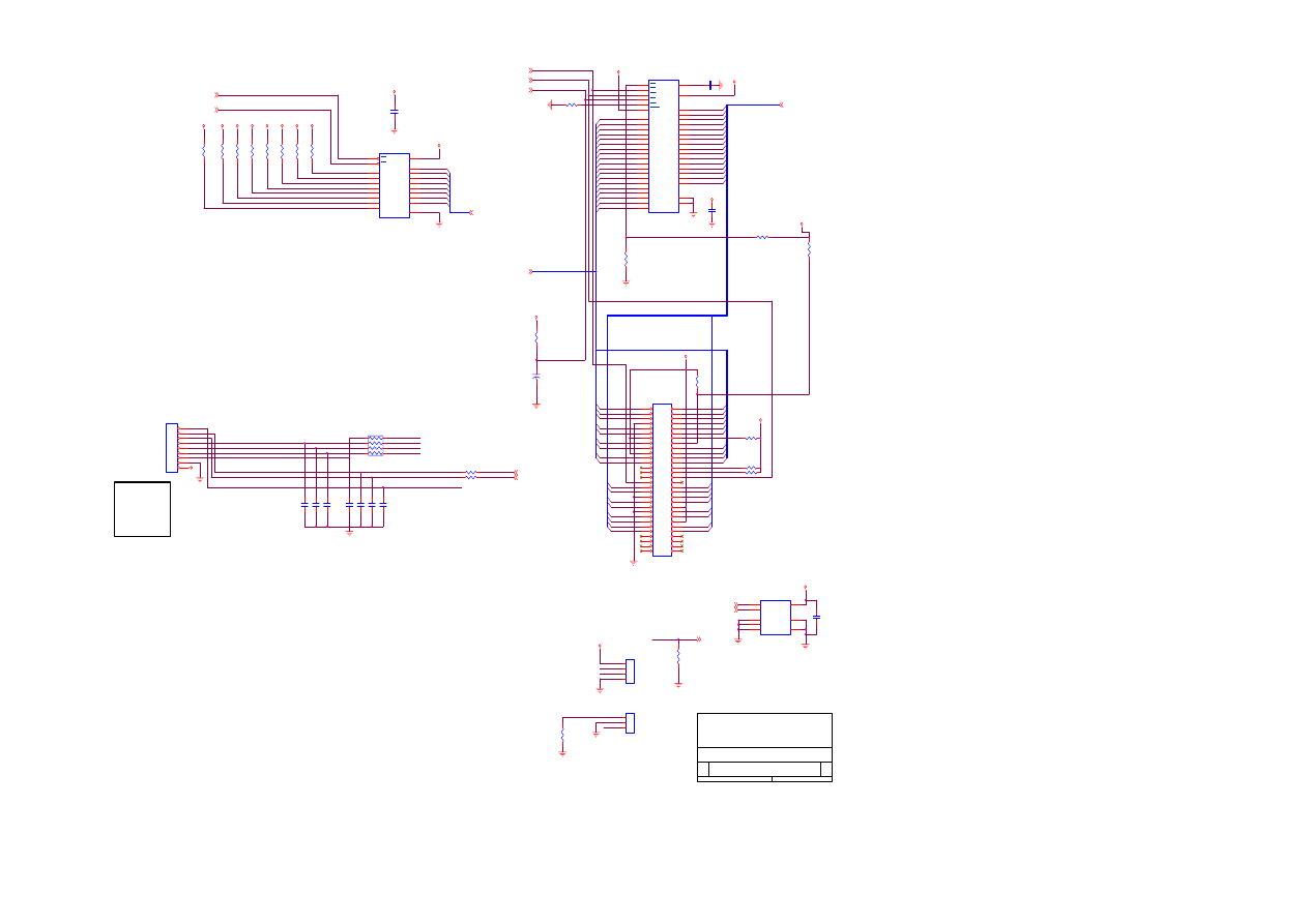
200-100-576D (PV6-D1)
S3
OUTPUT CONNECTOR
Proview Electronics (Taiwan) Co., LTD.
6F, NO.1, Pau-Sheng Rd., Yung-Ho City,
Taipei County, Taiwan R.O.C.
Tel: 886-2-2231-6789 Fax: 886-2-2232-4613
4
6
Friday, December 13, 2002
Title
Size
Document Number
Rev
Date:
Sheet
of
GND
GND
GND
GND
VCC
V33
GND
GND
GND
GND
GND
GND
CVDD
CVDD
CVDD
CVDD
GND
GND
GND
GND
GND
V33
CVDD
VCC
GND
LCDVDD
GND
GND
GND
GND
LVDSON
2
DRO[7:0]
2
DGO[7:0]
2
DBO[7:0]
2
DRE[7:0]
2
DGE[7:0]
2
DBE[7:0]
2
DCLK
2
DEN
2
DHS
2
DVS
2
LCDON
2
PVCC
LCDVDD
D-HSYNC
SHCLK
D-VSYNC
D-SHCLK2
BE4
RIN2-
RIN1-
GE5
RE3
RIN0-
RIN0+
CLK-
BE5
RE4
RE7
GE7
GE3
RE6
BE2
RE5
GE4
BE3
BE6
RIN1+
GE6
RE2
RIN2+
CLK+
GE2
BE7
GO4
GO3
GO5
GO2
GO0
GO1
GO6
GO7
BO0
BO2
BO1
BO3
RO0
RO2
RO7
RO4
RO3
RO6
RO5
BE5
BE1
BE2
BE6
BE3
BE4
BE0
BE7
GE1
GE2
GE4
GE6
GE5
GE3
GE0
GE7
RE6
RE3
RE0
RE5
RE1
RE2
RE4
RE7
D-VSYNC
D-HSYNC
D-SHCLK2
D-DE2
LVDSVCC
CLK+
RIN1-
RIN0-
LCDVDD
CLK-
LCDVDD
RIN2-
RIN2+
RIN1+
RIN0+
DBE7
DRE6
DGE5
DBE0
DRE4
DGE1
DBE4
DBE6
DGE3
DRE1
DGE2
DGE7
DBE5
DBE1
DBE2
DBE3
DGE0
DGE6
DGE4
DRE0
DRE7
DRE2
DRE3
DRE5
DGO6
DGO0
DRO7
DRO4
DGO7
DGO5
DGO3
DRO5
DBO4
DGO4
DGO2
DRO0
DGO1
DRO6
DRO2
DRO3
DRO1
DBO0
DBO3
DBO2
DBO1
BO4
BO5
BO6
BO7
DBO5
DBO6
DBO7
RO1
GND
RO5
D-SHCLK2
BO3
D-VSYNC
GND
GO4
GO3
BO6
RO4
GO0
GND
BO4
BO2
BO0
LCDVDD
LCDVDD
RO3
GO7
GO6
RO0
RO7
GND
GO2
D-DE2
GND
GND
RO6
RO2
GO5
BO7
D-HSYNC
BO5
GND
GND
GO1
RO1
GND
BO1
BE1
RE0
BE7
RE6
RE3
GND
GND
GND
GE3
RE5
BE5
GE4
GE1
BE4
GE6
GE2
RE2
RE1
RE7
RE4
BE3
BE0
GE7
GND
BE2
GND
GE0
GND
GE5
GND
GND
GND
BE6
RE5
RE3
GO3
GND
RO1
GND
LCDVDD
BE3
GO7
RO4
BO6
BE2
GE6
RE7
GE5
GND
GE7
D-SHCLK2
BE5
RO6
GND
GND
GO4
GND
GND
GND
GE4
BE6
GE3
BE0
D-DE2
RO7
GO2
D-HSYNC
GND
BO0
BO5
D-VSYNC
RE4
RE2
GO0
GND
RE0
GND
GND
RE6
RO0
GO1
RO3
BO2
GE0
GE1
GND
RO2
RE1
RO5
BO4
BO7
GE2
GO6
BE4
BE7
GO5
GND
GND
GND
GND
BE1
GND
BO3
BO1
D-DE2
CNA1
XF2H-4015-1
1
2
3
4
5
6
7
8
9
10
11
12
13
14
15
16
17
18
19
20
21
22
23
24
25
26
27
28
29
30
31
32
33
34
35
36
37
38
39
40
CNA2
XF2H-3615-1
1
2
3
4
5
6
7
8
9
10
11
12
13
14
15
16
17
18
19
20
21
22
23
24
25
26
27
28
29
30
31
32
33
34
35
36
R111
33R
R110
33R
R109
33R
R108
33R
R74
4.7K
C89
22pF
RP15
33X4
1
8
2
7
3
6
4
5
Q3
2N3904
B
E
C
C93
100uF/16V
BE0603
L13
RED
GREEN
BLUE
H_SYNC
V_SYNC
ENABLE
U9
SN75LVDS84A(NP)
44
45
47
48
1
3
4
6
7
9
10
12
13
15
16
18
19
20
22
23
25
26
41
40
39
38
35
34
33
32
2
5
11
17
24
46
37
36
31
42
27
29
30
28
8
21
D0
D1
D2
D3
D4
D5
D6
D7
D8
D9
D10
D11
D12
D13
D14
D15
D16
D17
D18
D19
D20
DCLK
Y0M
Y0P
Y1M
Y1P
Y2M
Y2P
TCLKM
TCLKP
VCC
GND
GND
GND
GND
GND
LVDSVCC
LVDSGND
LVDSGND
LVDSGND
SHTDN
PLLVCC
PLLGND
PLLGND
VCC
VCC
C94
0.1uF
RP9
33X4
1
8
2
7
3
6
4
5
R69
33R
L16
0R
1
2
+
C87
22u/6.3V
RP11
33X4
1
8
2
7
3
6
4
5
CN4
HEADER 20
1
2
3
4
5
6
7
8
9
10
11
12
13
14
15
16
17
18
19
20
R67
4.7K
R71
10K(NC)
R73
33R
BE0603
L12
CN3
FH-12-45S-0.5SH
1
2
3
4
5
6
7
8
9
10
11
12
13
14
15
16
17
18
19
20
21
22
23
24
25
26
27
28
29
30
31
32
33
34
35
36
37
38
39
40
41
42
43
44
45
L17
BE1206
C98
NC
R70
4.7k
C92
0.1uF
RP6
33X4
1
8
2
7
3
6
4
5
C91
NC
C88
0.1uF
C90
22pF
CN5
FH-12-30S-0.5SH
1
2
3
4
5
6
7
8
9
10
11
12
13
14
15
16
17
18
19
20
21
22
23
24
25
26
27
28
29
30
L15
33R
1
2
RP13
33X4
1
8
2
7
3
6
4
5
RP16
33X4
1
8
2
7
3
6
4
5
R68
33R
TU1
EMI KHLC-010(NP)
I
G
O
IN
GND
OUT
C75
0.1uF
L18
BE1206(NP)
L19
BE1206
C79
0.1uF
RP5
33X4
1
8
2
7
3
6
4
5
C76
0.01uF
C96
100uF/16V
U10
Si9435
4
6
3
7
2
1
8
5
C80
0.01uF
C77
0.1uF
RP12
33X4
1
8
2
7
3
6
4
5
RP8
33X4
1
8
2
7
3
6
4
5
C95
0.1uF
L14
BE0805(NP)
1
2
C97
0.1uF
+
C86
220uF/16V
RP7
33X4
1
8
2
7
3
6
4
5
RP14
33X4
1
8
2
7
3
6
4
5
C99
NC
C78
0.1uF
R72
10K
PS : SHCLK & D-SHCLK ADD GND
PS : SHCLK & D-SHCLK ADD GND
1
PANEL
20
M/B
1
20
1
DE
GND
GO7
GND
BO7
RO7
40
LCDVDD
BE7
36
1
GE7
RE0
RE7
GND
TM150XG-26L06A
PANEL
45
45
1
M/B
1
1
1
M/B
PANEL
30
30
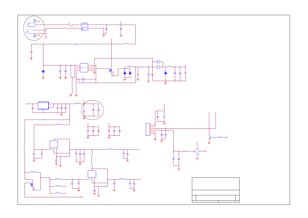
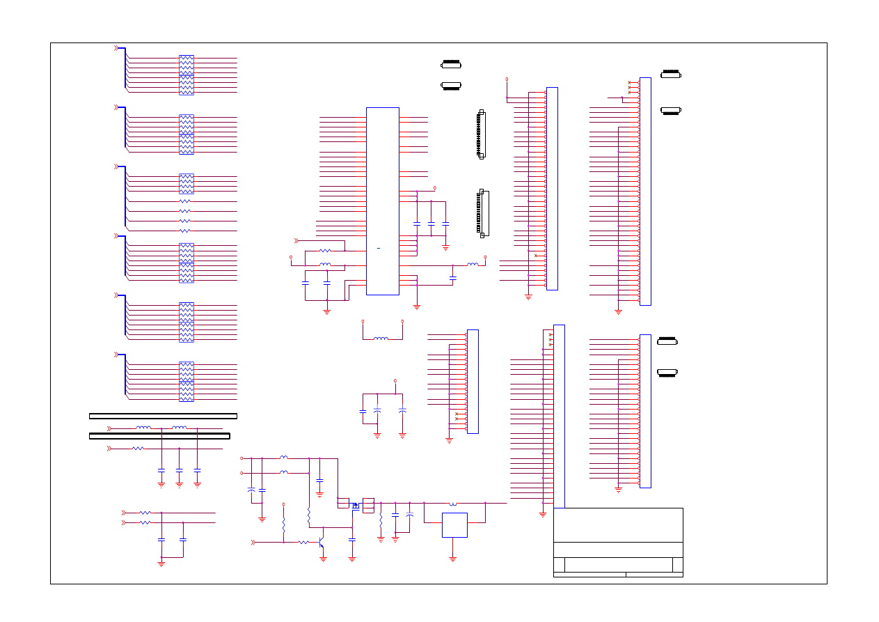
.
200-100-576D (PV6-D1)
S3
POWER SUPPLY
Proview Electronics (Taiwan) Co., LTD.
6F, NO.1, Pau-Sheng Rd., Yung-Ho City,
Taipei County, Taiwan R.O.C.
Tel: 886-2-2231-6789 Fax: 886-2-2232-4613
5
6
Friday, December 13, 2002
Title
Size
Document Number
Rev
Date:
Sheet
of
V33
3.3VADC
V18
VCC
VIN1
VCC
VIN
GND
GND
GND
GND
GND
GND
GND
GND
GND
GND
GND
GND
GND
GND
GND
GND
GND
VIN
V18A
3.3VDVI
3.3VADC
3.3VDVI
GND
GND
GND
GND
GND
GND
GND
GND
GND
GND
GND
GND
GND
GND
VE
VCC
V33
GND
BKLON
2
PWMOUT
2
DPMS
2
Bri
On/Off
VIN12V
V33A
VIN
C125
0.01uF
+
C126
10uF/16V
1
2
R112
NC
1
2
U3F
74LVC14-SOP14
13
12
14
7
R87
300
L33
BE0805
L32
BE0805
C149
220uF/16V
U14
LM1117
G
O
I
TAB
ADJ
Vo2
Vin
Vo4
C128
0.1uF
C150
10uF/16V
R86
680
C152
0.1uF
L25
BE0805
C151
0.1uF
L29 NC
C153
0.01uF
R85
2.2K
C154
0.01uF
R83
4.7K
L28
NC
R82 470
R81
4.7K
1
2
Q4
2N3904
B
E
C
Q5B
FDS4953
3
4
5
6
C156
10uF/16V
C155
10uF/16V
C127
0.1uF
C132
0.1uF
C157
0.1uF
C129
220uF/16V
R90
300
R89
680
U15
LM1117
G
O
I
TAB
ADJ
Vo2
Vin
Vo4
L24
BE0805
C71
0.01uF
C70
0.1uF
+
C43
220uF/16V
F1
FUS1206-5A
1
2
C103
0.1uF
C108
220uF/16V
C121
220uF/16V
D12
MMSZ5248B(NP)
A
C
C120
0.1uF
CN6
DC-JACK
1
2
3
4
5
C115
0.01uF
U13
AIC1084-33CM
<Part Type>
I
O
G
TAB
IN
OUT
C OUT1
C122
0.1uF
C107
0.01uF
U12
AIC1578-SO8
1
2
3
4
8
7
6
5
VIN
DUTY
SHDN
FB
CS+
CS-
DRI
GND
C130
100uF/16V
R75
JUMP WIRE15MM
L30
BE0805
C118
0.1uF
NP
S3
1
2
CN7
JST-2.0-6PIN
1
2
3
4
5
6
D13
1N5822(NP)
A
C
+
C116
220uF/16V
C123
0.01uF
C119
0.1uF
C109
0.1uF
C111
300p
R80
2K_1%
L21
BE1206
C110
220uF/16V
R79
6.2K_1%
D15
MMSZ5248B(NP)
A
C
C106
0.1uF
C113
220uF/16V
C100
0.01uF
C114
0.1uF
L23
BE1206
L20
JBT0385-100805-4
2
4
1
3
R76
0.02-1/4W
L22
47UH@3A
C112
0.1uF
C117
0.1uF
C131
0.01uF
R78
20K(NC)
C102
220uF/16V
L31
BE0805
+
C105
220uF/16V
C104
0.01uF
R77
10K
D14
SB340
A
C
C101
0.1uF
NP
S4
1
2
Q5A
FDS4953
1
2
7
8
C124
100uF/16V
L26
BE0805
L27
BE0805
3A
INVERTER I/F
Check DC jack pin defile
.
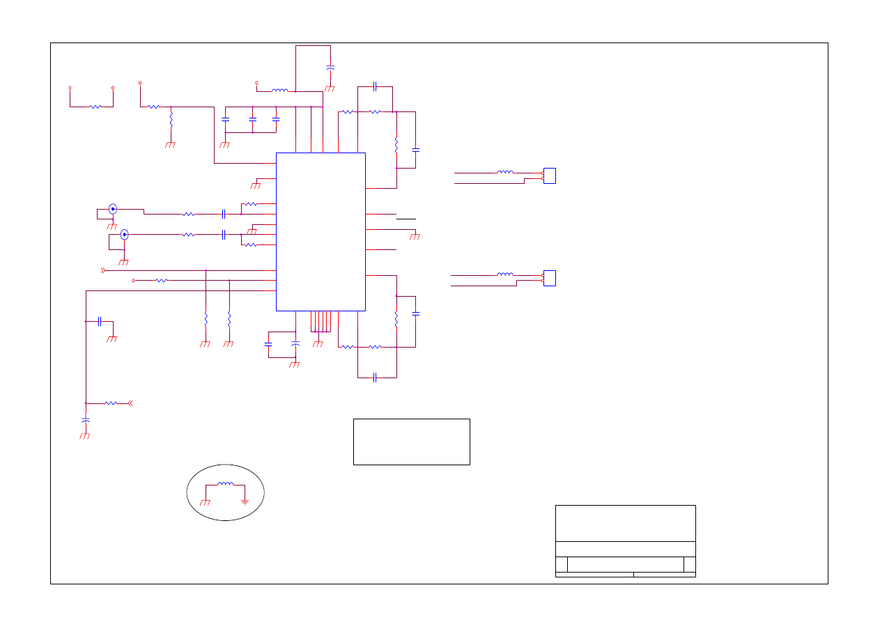
.
200-100-576D (PV6-D1)
S3
AUDIO4835
Proview Electronics (Taiwan) Co., LTD.
6F, NO.1, Pau-Sheng Rd., Yung-Ho City,
Taipei County, Taiwan R.O.C.
Tel: 886-2-2231-6789 Fax: 886-2-2232-4613
6
6
Friday, December 13, 2002
Title
Size
Document Number
Rev
Date:
Sheet
of
VDDA
VCC
VDDA
VDDA
VDDA
MUTE
2
VOLUME
2
VCC_AU
Right_outm
Right_Outp
Left_outp
Left_Outm
RIGHTIN
LEFTIN
Left_outp
AUD4835_DCVOL
L-SPOUT
Left_Outm
R-SPOUT
Right_Outp
Right_outm
R91
1K
C139 1UF
R96
20K
R102
10K(NC)
CN11
BASE2S
1
2
CN10
SCP606
1
3
2
C141 1UF
C138 1UF
R92
20K
U17
APA4835A
1 8 14 20 23
6
16
27
2
3
4
5
7
9
10
11
12
13
28
26
25
24
22
21
19
18
17
15
29
GND GND GND GND GND
VD
D
VD
D
VD
D
Shutdown
Gain Select
Mode
Mute
DC_Vol
Right Dock
Right In
Beep In
Lift In
Left Dock
Right Out+
Right Out-
R
ight
G
ain2
R
ight
G
ain1
Bypass
HP Sense
Li
ft Ga
in
1
Li
ft Ga
in
2
Lift out -
Lift out +
GND
C134
33PF
CN9
SCP606
1
3
2
R94
NC
R99
20K
R107
10K
C133
10uF/16V
1
2
R103
20K
C142
0.1uF
R105
33K
R104
20K
C137
0.068UF
R95
20K
R93
33K
R101
10K(NC)
+
C145
10uF/16V
1
2
C135
0.1uF
R98
20K
R97
20K
C136
0.1uF
C140
0.068UF
CN8
BASE2S
1
2
C144
33PF
L34
BE0805
1
2
C143
10UF/16V
1
2
L35
BE0603
L36
BE0603
R100
10K
C146
0.1uF
R114
BE0603
L37
BE0805
GAIN
HI HP OUT
SDWN
MODE
1
0
MODE VCC OP VOL
HI SHUTDOWN
MUTE
0
0
MODE GND OP MAX
1
HPS
LOW SP OUT
L-OUT
R-OUT
DEL L15
DEL L17
DEL C134
DEL R86
DEL R89
AUD4835_SD
. .

Memu..
Wyszukiwarka
Podobne podstrony:
Proview RA783 LCD Service Manual
Proview PZ456 LCD Service Manual
Proview SH770I LCD Service Manual
Proview SH970I LCD Service Manual
Proview SH770 LCD Service Manual
Proview AY965 LCD Service Manual
Proview RA783 LCD Service Manual
Proview PZ456 LCD Service Manual
Proview SH770I LCD Service Manual
Proview AY765 LCD Service Maunal
proviewHD972 service manual
więcej podobnych podstron