Disassembly
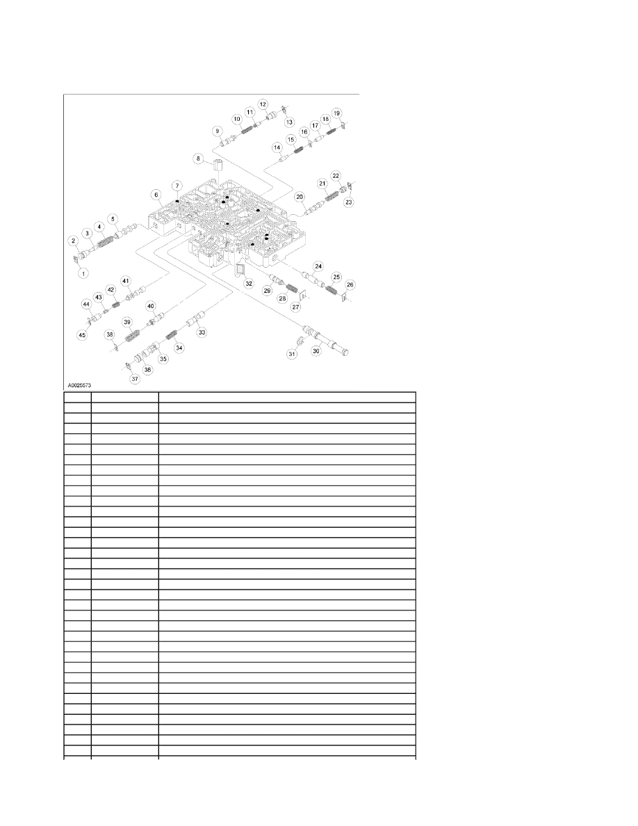
Main Control Valve Body Disassembled View
Item
Part Number
Description
1
—
Valve plug retainer (part of 7A100)
2
—
Main pressure booster valve sleeve (part of 7A100)
3
—
Main pressure booster valve (part of 7A100)
4
—
Main pressure regulator valve spring (part of 7A100)
5
—
Main regulator valve (part of 7A100)
6
7A100
Main control valve body assembly
7
7E195
Check ball (8 required)
8
7H171
Converter drain back valve
9
—
Overdrive servo regulator valve (part of 7A100)
10
—
Overdrive servo regulator valve spring (part of 7A100)
11
—
Overdrive servo regulator boost plunger (part of 7A100)
12
—
Overdrive servo regulator boost sleeve (part of 7A100)
13
—
Valve retainer (part of 7A100)
14
—
Capacity modulator valve (part of 7A100)
15
—
Capacity modulator valve spring (part of 7A100)
16
—
Spring retaining plate (part of 7A100)
17
—
Capacity modulator valve (part of 7A100)
18
—
Capacity modulator valve spring (part of 7A100)
19
—
Spring retaining plate (part of 7A100)
20
—
3-4 shift valve (part of 7A100)
21
—
3-4 shift valve spring (part of 7A100)
22
—
Valve retainer plug (part of 7A100)
23
—
Valve plug retainer (part of 7A100)
24
—
2-3 back out valve (part of 7A100)
25
—
2-3 back out valve spring (part of 7A100)
26
—
Spring retaining plate (part of 7A100)
27
—
Spring retaining plate (part of 7A100)
28
—
Pressure regulator valve spring (part of 7A100)
29
—
Pressure regulator valve (part of 7A100)
30
—
Control manual valve (part of 7A100)
31
—
Retaining ring (part of 7A100)
32
—
Solenoid screen
33
—
1-2 shift valve (part of 7A100)
34
—
2-3 shift valve spring (part of 7A100)
Page 1 of 5
2004 F-150 Workshop Manual
3/15/2010
http://www.fordtechservice.dealerconnection.com/pubs/content/~WS42/~MUS~LEN/19/S...
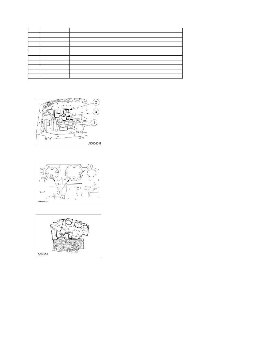
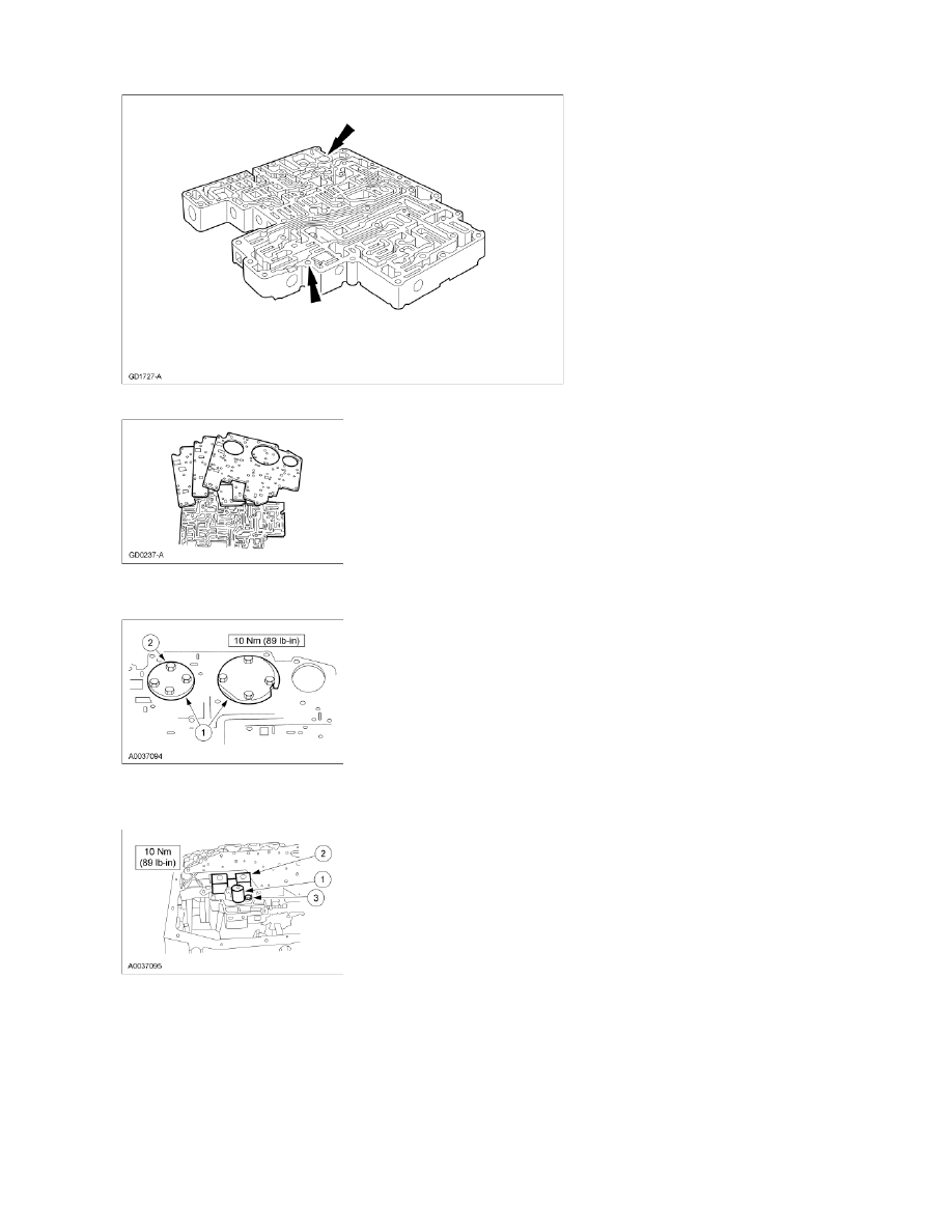
1.
Remove the torque converter clutch (TCC) solenoid and the shift solenoid.
1.
Remove the retaining bolt.
2.
Remove the shift solenoid.
3.
Remove the TCC solenoid.
2.
Remove the 2 reinforcement plates.
1.
Remove the bolts.
2.
Remove the plates.
3.
Remove the separator plate and discard the gaskets.
4.
NOTE: Note the location of the eight coasting booster valve shuttle balls for assembly.
Remove the 8 coasting booster valve shuttle balls.
35
—
2-3 valve (part of 7A100)
36
—
Valve retaining plug (part of 7A100)
37
—
Valve plug retainer (part of 7A100)
38
—
Spring retaining plate (part of 7A100)
39
—
Pressure regulator valve spring (part of 7A100)
40
—
Pressure regulator valve (part of 7A100)
41
—
Bypass clutch control valve (part of 7A100)
42
—
Bypass clutch control valve spring (part of 7A100)
43
—
Bypass clutch control valve plunger (part of 7A100)
44
—
Bypass clutch control plunger sleeve (part of 7A100)
45
—
Control valve plate (part of 7A100)
Page 2 of 5
2004 F-150 Workshop Manual
3/15/2010
http://www.fordtechservice.dealerconnection.com/pubs/content/~WS42/~MUS~LEN/19/S...
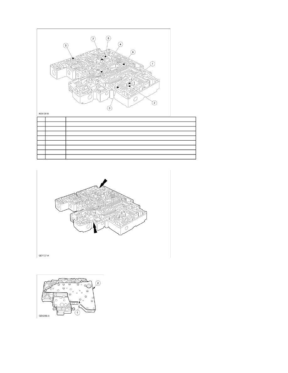
5.
Remove the converter drain back valve and solenoid pressure supply screen.
6.
Remove the main control valve body cover plate.
1.
Remove the 13 main control valve body cover plate bolts.
2.
Remove the main control valve body cover plate.
Assembly
NOTE: Inspect the shift solenoid O-rings and TCC solenoid O-rings for damage.
1.
Install the valve body cover plate.
1.
Position the valve body cover plate gasket and cover plate.
Item
Part Number
Description
1
7E195
Check ball (B9) located in the forward clutch circuit near the 3-4 shift valve
2
7E195
Check ball (B2) located in the direct clutch circuit near the 2-3 backout valve
3
7E195
Check ball (B3) located in the overdrive and forward clutch circuits near the 1-2 shift valve
4
7E195
Check ball (B4) located in the reverse circuit near the orifice 1
5
7E195
Check ball (B5) located between the reverse, LS modulator and the low reverse servo circuits
6
7E195
Check ball (B6) located between the L, 2, 3, 4 and the torque converter clutch (TCC) circuits
7
7E195
Check ball (B7) located between the L, 2, 3, 4 and the intermediate clutch circuits
8
7E195
Check ball (B8) located between the forward clutch and the 23 BP circuits
Page 3 of 5
2004 F-150 Workshop Manual
3/15/2010
http://www.fordtechservice.dealerconnection.com/pubs/content/~WS42/~MUS~LEN/19/S...
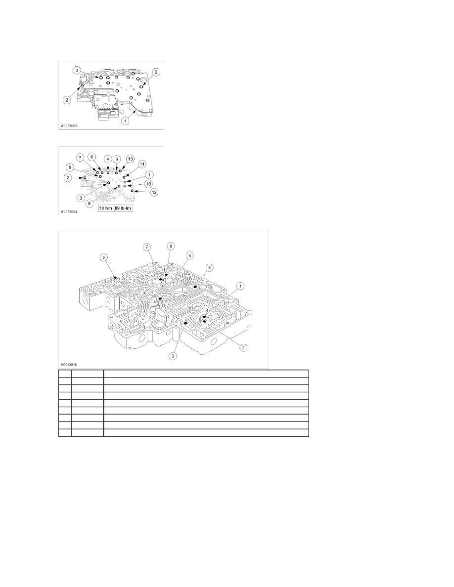
2.
Loosely install the 2 guide pin bolts.
3.
Loosely install the remaining bolts.
2.
Tighten all the bolts in the sequence shown.
3.
Install the 8 coasting booster valve shuttle balls.
4.
Install the converter drain back valve and solenoid pressure supply screen.
Item
Part Number
Description
1
7E195
Check ball (B9) located in the forward clutch circuit near the 3-4 shift valve
2
7E195
Check ball (B2) located in the direct clutch circuit near the 2-3 backout valve
3
7E195
Check ball (B3) located in the overdrive and forward clutch circuits near the 1-2 shift valve
4
7E195
Check ball (B4) located in the reverse circuit near the orifice 1
5
7E195
Check ball (B5) located between the reverse, LS modulator and the low reverse servo circuits
6
7E195
Check ball (B6) located between the L, 2, 3, 4 and the torque converter clutch (TCC) circuits
7
7E195
Check ball (B7) located between the L, 2, 3, 4 and the intermediate clutch circuits
8
7E195
Check ball (B8) located between the forward clutch and the 23 BP circuits
Page 4 of 5
2004 F-150 Workshop Manual
3/15/2010
http://www.fordtechservice.dealerconnection.com/pubs/content/~WS42/~MUS~LEN/19/S...
5.
Install the separator plate and gaskets.
6.
Install the 2 reinforcement plates.
1.
Position the plates.
2.
Install the reinforcement plate bolts.
7.
Install the shift solenoid.
1.
Position the TCC solenoid.
2.
Position the shift solenoid.
3.
Install the bolt.
Page 5 of 5
2004 F-150 Workshop Manual
3/15/2010
http://www.fordtechservice.dealerconnection.com/pubs/content/~WS42/~MUS~LEN/19/S...
Wyszukiwarka
Podobne podstrony:
Historia prawa polskiego wyk 10 2010 03 16
2010 03 Ratownictwo medyczne Podlasin
2010 03 Urazy sportoweid 26986 Nieznany (2)
2010 03, str 050 052
Prawo cywilne wyk.13 2010-02-16, Prawo Cywilne
2010 03 04
Podatki w Działalności Gospodarczej wykłady 2013 03 16
2010 03 02
arkusz kalkulacny technilogia V sem, do uczenia, materialy do nauczania, rok2009 2010, 03.01.10
2010 03 21 pieniadz
2010 03, str 150 153
2010 03 Gnome on Edge
2010 12 16 trm wyklad
2010 03 10
IS wyklad 03 16 10 08 MDW id 22 Nieznany
03 2010 03 31id 4284
2010 03, str 040 044
więcej podobnych podstron