
Full Paper
Modification and tuning of diesel bus engine for biogas
electricity production
Sittiboon Siripornakarachai
*
and Thawan Sucharitakul
Department of Mechanical Engineering, Faculty of Engineering, Chiang Mai University,
Chiang Mai 50200, Thailand
* Corresponding author, e-mail : siripornakarachai@yahoo.com and thawan@dome.eng.cmu.ac.th
Received: 19 September 2007 / Accepted: 2 November 2007 / Published: 9 November 2007
Abstract: This study is to convert and tune a bus diesel engine for electricity production in
a farm using biogas as fuel. The engine under study was a Hino K-13CTI 13,000cc 24 valve
turbocharged engine coupled to a 3-phase 4-pole induction motor to produce electricity at
50 Hz. Modifications included an addition of biogas carburettor for air-fuel mixing,
replacing the fuel injection system with spark ignition system, reduction of compression
ratio from the original 16:1 to 8:1 using a cylinder head spacer, and modification of the
turbocharger waste gate so the boost pressure can be adjusted. When the induction motor
was synchronised to the power grid, the running speed of the engine was 1,500 rpm.
Optimal engine efficiency was achieved at 28.6% by setting the lambda factor at 1.097,
ignition timing at 54
o
before top dead center, and the turbocharger boost at 56 kPa. With this
setting, the generator power output was 134.20 kilowatt with emission of CO and NO
X
being 1,154 and 896 ppm respectively.
Keywords: modification engine, engine for electricity, biogas engine, engine for biogas, gas
engines
Introduction
Biogas is a by-product of waste treatment in animal farms and can be used to replace fossil fuel to
produce electrical energy. Biogas is formed by digestion of animal waste by anaerobic bacteria and the
approximate composition is 60-80% methane, 20-40% carbon dioxide, and about 1% hydrogen sulfide

195
and other trace gases. Biogas has a liquefying pressure of 200-300 bar and a heating value of about
23,400 kJ/m
3
[1,2]. The gas density is 1.2 kg/m
3
and has research octane number (RON) of about 130
[2,3]. From the above properties, it can be seen that it is difficult to liquefy biogas for storage or
transport and it is quite suitable to be used as fuel in an internal combustion engine [4,5]. Statistics as
of 2006 shows that in Thailand there are pig farms which have biogas waste treatment system that can
produce biogas totalling 35,000,000 cubic metres per year. If all are used to produce electricity, the
total energy of 35,000,000 kilowatt-hour can be produced per year [6]. With an increase in biogas
production towards larger quantities, such technical utilisation as the transformation into mechanical
energy becomes an issue to be researched on. While larger engines specifically designed for gas are on
the market, smaller engines modified from standard Otto or diesel engines are seen to fill the gap for
small-to-medium and decentralised applications. Indian [7,8], Chinese [9], and French [10]
publications mainly dealt with the modification of small stationary diesel engines for dual fuel
operation. Others went on to modify medium-sized diesel engines including their governors [11], or
researched on the performance parameters of dual fuel biogas engines in more detail [12].
In Thailand, the bus is an expensive commodity compared to per capita income. As a result, buses
are kept running long beyond its life expectancy set by the manufacturer. To keep these buses running,
skilled mechanics as well as used engine markets and spare parts are well developed in Thailand. A
used bus engine imported from Japan in a reasonably good condition can be had for about 5,500 US
dollars. The cost for engine overhaul after about 1,000,000 kilometers of use is about 1,400 US dollars.
With a used bus engine coupled to an electrical generator, a farm owner can make a 130 kilowatt
power generator fueled by biogas for about 23,100 US dollars and the break-even of the investment
can be as short as one year. These engines do not use a proper gas carburettor and are seldom tuned for
best efficiency or low pollution [13]. This project is to investigate the proper adaptation of engine for
durability and tune it for high efficiency and low emission.
Just about any engine can be converted to run on biogas and produce electricity in a farm. Smaller
engines (under 5,000 cc capacity) are normally designed to perform best at higher engine speed and
are normally not designed for full capacity output like those required in electrical power production
[14]. On the other hand, larger engines like those found in heavy trucks or large buses are designed to
carry a full load for most of its operating cycle and are also designed to run at lower engine speed. As
a result, car engines will last about 150,000 kilometers between overhauls while buses and large trucks
engines are expected to last more than 1,000,000 kilometers between overhauls. The long operating
life of large engine makes it more suitable for electricity production in a farm and will probably cost
less in the long run to operate [13].
Few variables need to be considered before the attempted adaptation of a diesel engine for
electricity production. First consideration is given to the overall engine design itself. The engine will
need to run at the generator synchronization speed to work as a generator. In this case, the generator
requires the engine speed of 1,500 rpm for a four-pole generator and 3,000 rpm for a two-pole
generator. The bus engine under consideration provides maximum torque at 1,500 rpm so it is suitable
for the 1,500 rpm running speed. Another variable to be considered is the feasibility of reducing the
compression ratio down to the spark ignition range. An overhead camshaft engine would be easy to
adapt but the engine under consideration can also be adapted if the valve pushrod can be extended to
accommodate the additional distance between the camshaft and the rocker arm, due to the thickness of

196
the cylinder head spacer. The space issue when replacing the fuel injectors with spark plugs also needs
to be considered before the adaptation.
This study aims to adapt a large diesel engine to run on biogas only and the adaptation involves an
addition of biogas carburettor for air-fuel mixing, replacing the fuel injection system with spark
ignition system, reducing the compression ratio to suit biogas fuel using a cylinder head spacer, and
modification of the turbocharger waste gate so the boost pressure can be adjusted. The test rig used a
Hino K-13CTI 13,000cc 24 valve turbocharged engine coupled to a 3-phase 4-pole induction motor to
produce electricity at 50 Hz. The engine was then tuned by changing air/fuel ratio, ignition timing, and
turbocharger boost pressure to obtain the optimal running condition.
Materials and Methods
The Hino K-13CTI engine being studied was a turbocharged bus diesel engine that came with a fuel
injection system as well as a high compression ratio of 16:1 and a fixed waste gate boost control. For
biogas fuel adaptation, a biogas carburettor was designed, manufactured, and installed. The fuel
injection system was replaced with a spark ignition system, the compression ratio was reduced to 8:1,
and the waste gate was modified so the boost pressure could be adjusted. Each of these modifications
is discussed in turn in the following section of the paper.
Carburettor design
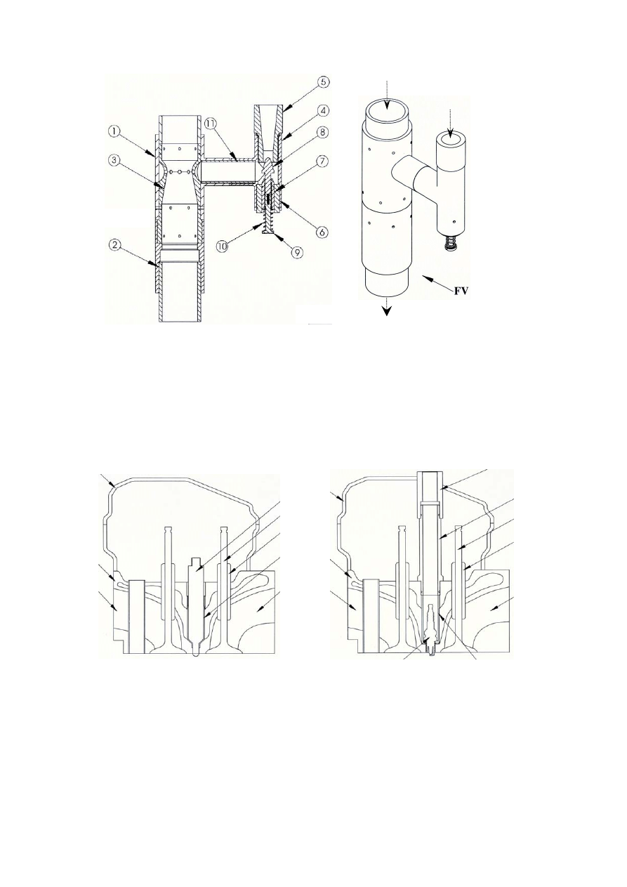
The biogas carburettor designed and installed in this study is shown in Figure 1. A literature survey
shows that a suitable carburettor for a biogas engine should be a venturi with the accelerator cone
being tapered as a curve of 40 mm radius and the diffuser cone angle of 10
o
. The biogas is fed into the
venturi through multiple circular ports around the throat area and the throat air velocity should be
between 100 to 150 meters/second [2]. With this information, a carburettor designed for the 13,00cc
engine operating at 1,500 rpm should have the throat diameter of 7.5 mm. The metering needle for the
gas inlet was fabricated with a square root profile to provide some linearity between the needle
position and the gas flow rate. The venturi was machined from aluminum stock and the carburettor
body was fabricated from PVC pipe parts.
Spark ignition
The distributor and ignition coil was adapted from the one used in 6-cylinder Toyota 5-ME engine.
The vacuum and centrifugal advance was disabled because the engine would run at a constant speed
and a full load when used to drive the generator. The distributor was driven by the original fuel
injection distributor mechanism. The fuel injection nozzle in the cylinder head was removed and
replaced with a spark plug and an appropriate guide tube. The spark plug modification detail is shown
in Figure 2.
197
Figure 1. Biogas carburettor design: (1) Venturi housing, (2) Venturi base, (3) Venturi mixer,
(4) Metering housing, (5) Main jet, (6) Metering adjusting nut spacer, (7) Metering adjusting
nut, (8) Metering needle, (9) Metering adjusting screw, (10) Return spring, and (11) Pipe
junction
Figure 2. Cutaway view of the modified cylinder head: (1) Valve cover, (2) Cylinder head,
(3) Intake port, (4) Exhaust port, (5) Valve guide, (6) Exhaust valve, (7) Diesel injection
nozzle guide, (8) Diesel injection nozzle, (9) Spark plug guide, (10) Middle spark plug rod
guide, (11) Upper spark plug rod guide, and (12) Spark plug
Air
Biogas inlet
Gas mixer outlet
(A) Before modification
1
2
3
4
5
6
7
8
1
2
3
4
5
6
9
12
10
11
(B) After modification
198
Compression ratio
For proper biogas operation, the compression ratio needs to be brought down from the original 16:1
to some lower value to avoid engine knock. Literature suggests that the compression ratio should be
between 10:1 and 12:1 for biogas operation [2]. Since a turbocharger would be used, the compression
ratio was further lowered to 8:1. To achieve this, a steel spacer 10 mm thick was fabricated for this
purpose.
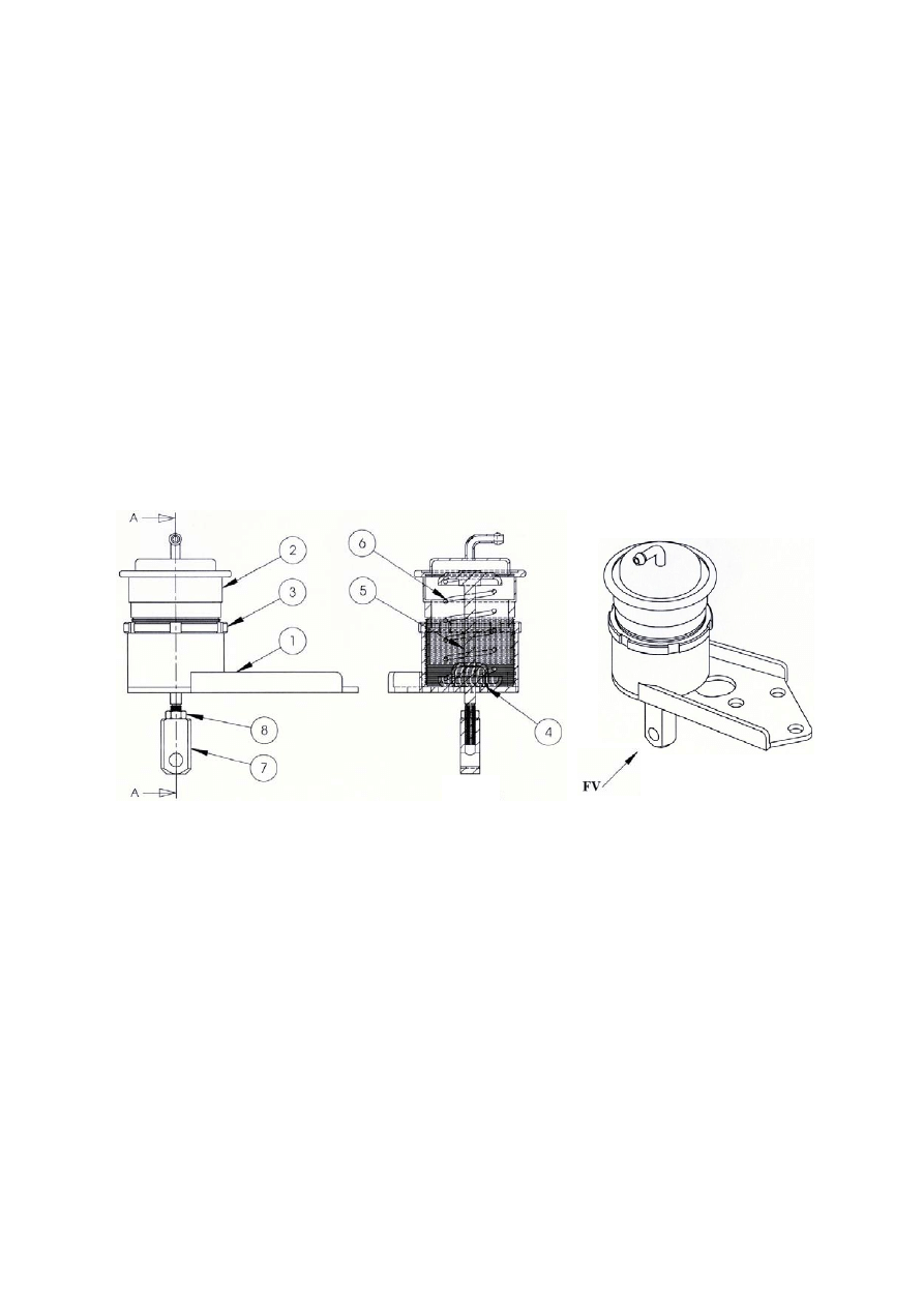
Turbocharger boost pressure
The turbocharger pressure is another parameter to be optimised. Too low pressure will cause loss of
efficiency while too much boost will cause knocking, which can damage the engine in the long run.
The boost pressure in the experimental engine was varied by modifying the waste gate spring housing
so it could be adjusted to vary the turbocharger pressure. After the modification, the turbocharger
boost could be adjusted between 40 kPa and 80 kPa. Details of the modification are in Figure 3.
Figure 3. Modified waste gate from standard waste gate for adjustable turbocharger pressure:
(1) Waste gate base, (2) Waste gate spring housing, (3) Waste gate adjustment lock nut,
(4) Push rod bushing, (5) Waste gate push rod, (6) Return spring, (7) Adjustable push rod
joint, and (8) Lock nut
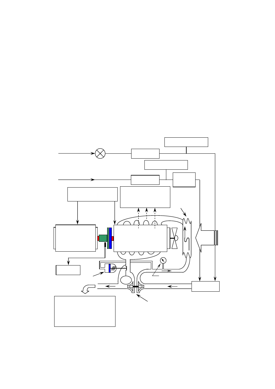
Test Rig Description
The purpose of this experiment is to find an optimal tuning condition when a bus diesel engine is
modified and converted to a spark ignition engine which will be fueled by biogas to drive an electrical
generator to produce electricity. Inlet air and biogas were monitored so air/fuel ratio could be
calculated. Exhaust gas was also checked for carbon monoxide and oxide of nitrogen emission at
various engine settings. Each component of the test rig is briefly described in the following section.
The overall block diagram of the test rig is shown in Figure 4.
A-A
199
Test engine
The test engine was a Hino 13,000cc diesel engine with 4 valves per cylinder, modified for biogas
fuel as described above. The engine model was K-13CTI and was normally installed in buses in
Thailand. This engine was chosen because of used engine availability and commonly available spare
parts. It was overhauled to new engine specification before testing and is currently undergoing
endurance test at 4T farm, Chiang Mai, Thailand.
Electrical generator unit
The generator used was a 3-phase 4-pole 132-kW generator with an induction motor made by
HASCON, model number 200L2-2. The generator was directly coupled by a clutch mechanism to the
test engine and was synchronised to the power grid when in operation. The nominal operating speed
was 1,500 rpm.
Figure 4. Block diagram of the test rig
Biogas main
Air main
Safety & Control unit
Cooling water, Gas
mixer & Oil lubricant
CO, O
2
, NO
X
emission
analyzer & Exhaust gas
temperature meter
Crank angle signal
Ball valve
Turbocharger
Intercooler
Adjustable waste gate
Air flow
Pressure gage
Temperature meter
Temperature meter
Four stroke engine
with spark ignition
Gas meter
Air filter
Gas meter
Three phase
induction motor
Monitor
Carburettor

200
Control unit
Biogas Advisory Unit, Chiang Mai University, designed the control unit and the blueprint was
available to the public at no cost. It was used to start the test engine, synchronise the generator with the
power grid, as well as monitor safety function in the case of gas supply shortage, short circuit,
overloading in power grid, engine overheating, loss of oil pressure in the engine, or power grid failure.
Intake air measurement
Intake air flow rate was measured using a Kobold gas flow meter model GVPA-303-GDR.
Intake biogas measurement
The composition of inlet biogas varies with the type of animal waste used to produce the gas as well
as the ambient temperature in which the fermentation occurs. In general, biogas contains carbon
dioxide, methane and one percent of other trace gases. The methane content of biogas can be
determined by finding the amount of carbon dioxide, adding 1 percent to the amount and subtracting
this from 100, thus yielding the percentage by volume of methane. The amount of carbon dioxide in
the biogas was determined by using the Brigon IND 60 gas analyser. The volume flow rate of biogas
was measured using a Kobold gas flow meter model GVPA-303-GDR.
Exhaust gas measurement
A flue gas analyser (Testo 300XL-1) was used to monitor the quantity of O
2
, CO, and NO
X
in the
exhaust gas. The probe attached could also measure the exhaust gas temperature as well.
Ignition timing measurement
Ignition timing was measured by a timing light (Sincro model DG86) with trigger signal from the
high tension wire from the distributor to cylinder number one spark plug.
Power output measurement
The power output from the generator was monitored by Curcutor model AR5 supply network
analyser.
Experimental Procedure
The experiment was carried out using the following steps to collect data for analysis.
Turbocharger pressure adjustment
The engine was run on biogas with RON of about 130. To get the most benefit from the higher
RON, higher compression ratio was used for higher thermal efficiency [15-18]. The proper
compression ratio for the spark ignition engine to be run on biogas fuel was between 10 to 12:1 [2].

201
While a naturally aspirated spark ignition engine may have sufficient margin of safety relative to
knock to allow modest inlet-air boost, any substantial air compression prior to cylinder entry will
require changes in engine design and/or operating variables to offset the negative impact on knock.
The variables which were adjusted to control knock in a turbocharged SI engine were: compression
ratio, spark retard from optimum, charge air temperature, and air/fuel equivalence ratio [18]. Therefore
the cylinder head was installed with a spacer to increase the combustion chamber volume and produce
lower compression ratio. The experiment would start at the compression ratio of 8:1 and the
turbocharger pressure was adjusted by the waste gate at 40 kPa and increased at an increment of 4 kPa
until engine efficiency began to decrease.
Initial air/fuel mixture adjustment
The engine was started, the ignition timing was set at about mid range (55
o
BTDC) and the air/fuel
mixture screw (metering adjustment screw in the carburetor) was adjusted to the position that the
engine just ran smoothly (lean mixture).
Initial ignition timing adjustment
The ignition timing was set at 50
o
BTDC at the beginning of a data collection.
Data collection
The recording of the following set of data was performed: air temperature, biogas temperature
before and after boost by turbocharger and after cooling by intercooler, engine coolant temperature,
lubricating oil temperature, exhaust gas temperature, air and biogas consumption rate, ignition timing,
generator power output, oxygen remaining after combustion, carbon monoxide and oxide of nitrogen
in the exhaust gas.
Ignition timing increment
The ignition timing was advanced 2
o
and the data above were again collected. The process was
repeated until the ignition timing reached 60
o
BTDC or excessive pre-ignition was
observed.
Air/fuel mixture increment
After a set of data was collected, the air/fuel mixture screw was turned half a revolution in the rich
direction. Another set of data was collected and the process was repeated until the mixture was too rich
for the engine to run smoothly.
Results
The collected data were processed into excess air ratio (
λ), engine efficiency, and then the system
efficiency (overall efficiency), power output, exhaust gas temperature, specific biogas consumption,
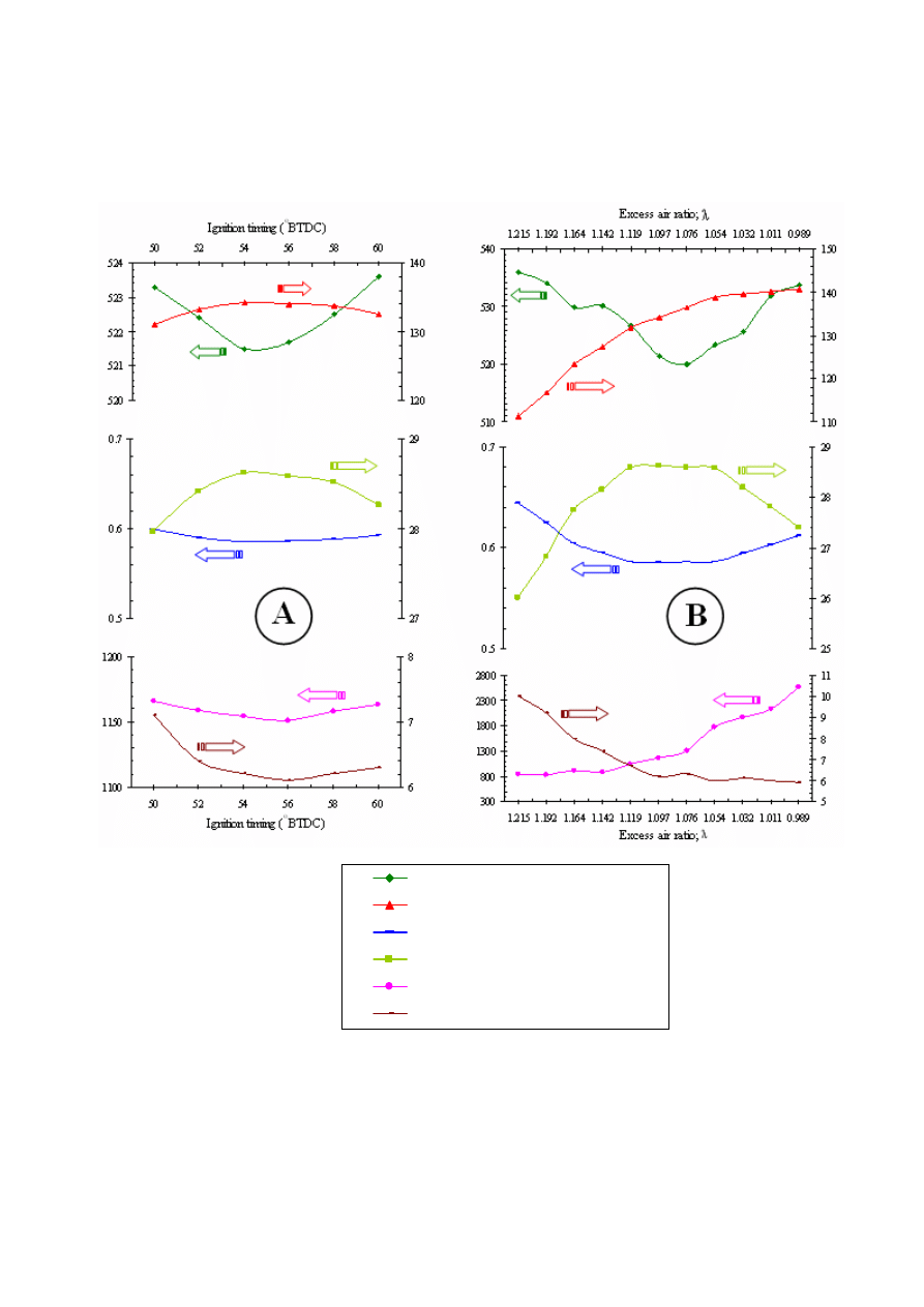
202
oxygen quantity in exhaust gas, carbon monoxide and oxide of nitrogen emission were plotted against
the ignition timing, excess air ratio, and turbocharger pressure. The resulting graphs are shown in
Figures 5-7.
Exhaust gas temperature;Tfg (oC)
Actual Electric Power Output (kW)
Specific Biogas Consumption (m3/kWh)
Engine efficiency (%)
Carbon monoxide;CO (ppm)
Oxygen;O2 (%)
Figure 5. Exhaust gas temperature, electric power output, specific biogas consumption, engine
efficiency, carbon monoxide, and oxygen for compression ratio of 8:1 and turbocharger
pressure setting at 56 kPa plotted against: (A) Ignition timing, and (B) Excess air ratio.
203
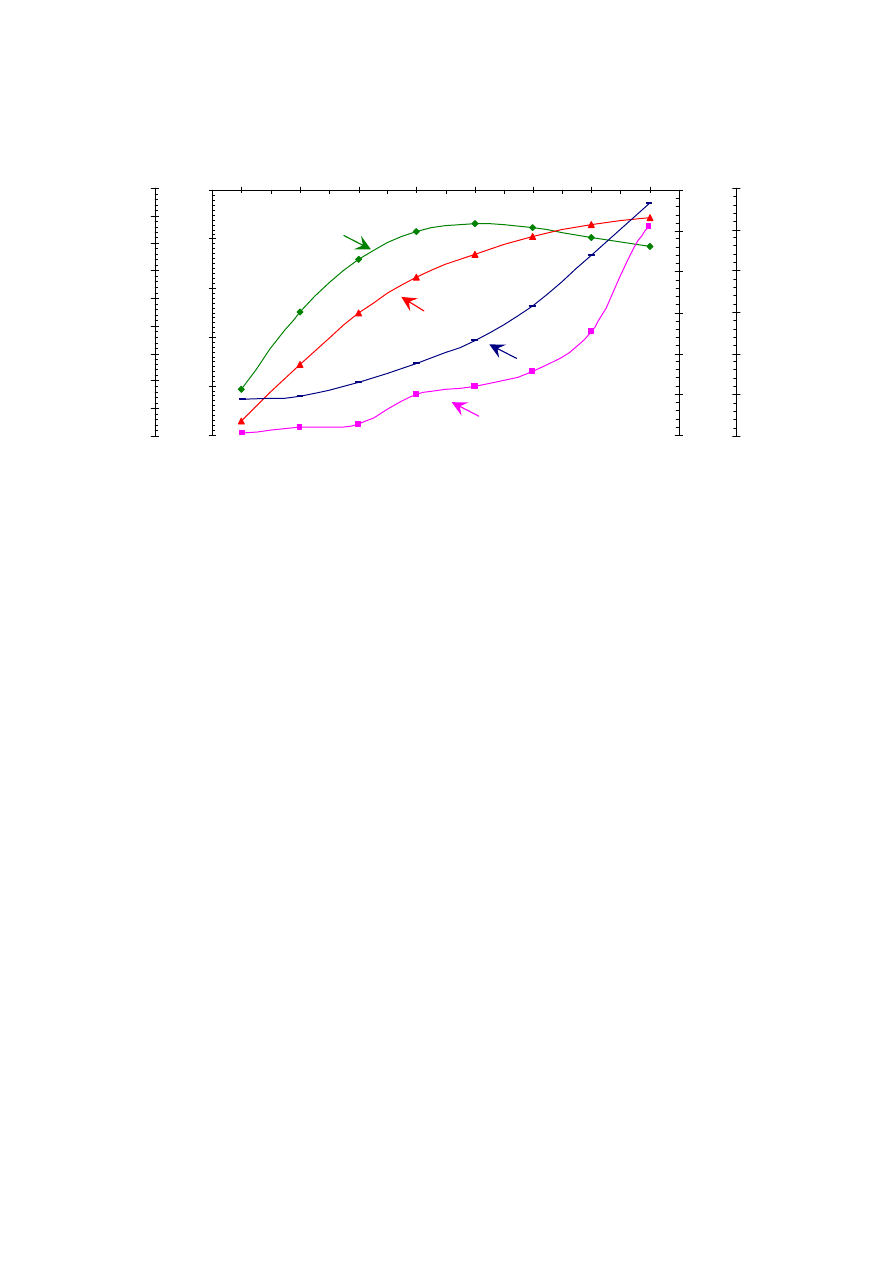
Figure 6. Output power, engine efficiency, carbon monoxide and oxide of nitrogen plotted against
turbocharger boost pressure.
Discussion
Effect of Ignition Timing on Engine Performance
From Figure 5(A) it can be seen that the maximum engine efficiency and maximum output power
can be achieved at 54
o
BTDC ignition timing. When the timing is retarded from the optimal setting,
the combustion process is completed after the bottom dead center position of the crankshaft and the
thermal energy transferred to shaft power is reduced. The result is higher exhaust gas temperature as
shown in the graph. If the ignition timing is advanced beyond the optimal point, knocking occurs,
resulting in excessive combustion temperature and increase in NO
X
and CO emission.
Effect of Air/Fuel Mixture on Engine Performance
Figure 5(B) shows that the optimal excess air ratio for this engine is 1.097. Leaner mixture results
in lower flame speed and incomplete combustion, which leads to high exhaust gas temperature. Rich
mixture can lead to engine knock and results in higher NO
X
and CO emission as well as high exhaust
temperature.
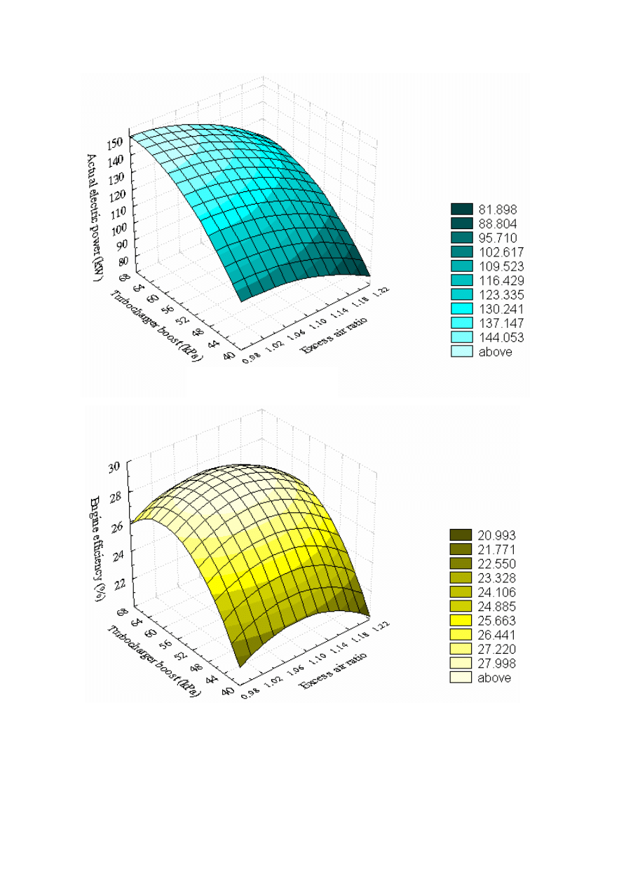
Effect of Turbocharger Boost Pressure on Engine Performance
Figures 6 and 7 show that the increase in turbocharger boost pressure can increase the engine output
even though the engine efficiency has dropped off at higher boost pressure. Increasing the boost
pressure beyond the maximum efficiency point results in high CO and NO
X
emission as well as
excessive engine vibration and it appears that the increased engine output is not worth the increased
pollution and shortened engine life due to vibration.
20
22
24
26
28
30
90
100
110
120
130
140
150
40
44
48
52
56
60
64
68
E
ng
in
e e
ff
ici
en
cy
(
%
)
Turbocharger pressure (kPa)
A
ct
ual
el
ect
ri
c p
ow
er
o
ut
pu
t (
kW
)
0
500
1000
1500
2000
2500
3000
3500
4000
4500
0
500
1000
1500
2000
2500
3000
O
xid
e o
f n
itr
og
en
; N
O
X
(p
pm
)
C
ar
bo
n m
on
oxi
de
; C
O
(p
pm
)
Engine efficiency
Actual electric power
Carbon monoxide
Oxide of nitrogen
204
Figure 7. Power output (A) and engine efficiency (B) plotted against excess air ratio and
turbocharger pressure at compression ratio of 8:1
Engine efficiency (%)
Electric power output (kW)
(A)
(B)

205
Three categories of tuning optimisation were done. The categories are lowest CO emission, highest
engine efficiency, and highest power output. The tuning parameters and collected data for the three
categories are presented in Table 1.
With the presented data, it can be shown that a large diesel engine can be economically adapted for
power generation in a farm. The payback period is less than one year and when properly tuned, the
engine passes the internationally accepted pollution control standard of carbon monoxide of a vehicle
engine [19, 20].
Table
1. Summarised data of fine tuning of biogas engine for optimum operation when compression
ratio is 8:1 and turbocharger boost pressure is 56 kPa
Item
Lowest CO
emission
Highest engine
efficiency
Highest
power output
1. Optimum ignition timing (
o
BTDC)
57
54
52
2. Excess air ratio; λ 1.215
1.097
0.989
3. Fuel consumption; f
C
(m
3
/hr) 71.80
78.60
86.10
4. Specific fuel consumption; sfc (m
3
/kWh) 0.64 0.59 0.61
5. Actual electric power output; P
EL
(kW)
111.40
134.20
140.70
6. Engine efficiency; η
eng
(%)
26.01
28.63
27.40
7. Overall efficiency; η
tot
(%) 23.41
25.76
24.66
8. Oxide of nitrogen emission; NO
X
(ppm)
511
896
843
9. Carbon monoxide emission; CO (ppm)
854
1,154
2,576
10. Oxygen in exhaust gas; O
2
(%)
10.00
6.20
5.90
11. Engine coolant temperature; T
eng
(
o
C) 88.2
88.7 89.0
12. Lubricating oil temperature; T
oil
(
o
C) 87.8
87.2
87.6
13. Exhaust gas temperature; T
fg
(
o
C) 536.0
521.5
533.8
14. Payback period (year)
0.78
0.52
0.49
Conclusion
In this study, engine performance and pollution figures are recorded for a range of engine tuning
parameters, viz. turbocharger boost, ignition timing and excess air ratio. The compression ratio was set
at 8:1 and the turbocharger boost was varied by adjusting the waste gate. When the system was
operating at 1,500 rpm, the range of engine setting was as follows: excess air ratio between 0.9 to 1.2,
ignition timing between 50
o
to 60
o
before top dead center, and turbocharger pressure setting between
40 to 68 kPa. Under these operating conditions, the engine efficiency increased as the boost was
increased from 40 to 56 kPa and there was a slight increase of NO
X
and CO as the boost went up. As
the boost was increased from 56 kPa to 68 kPa, the engine efficiency began to decrease and the
amount of pollution was increased. Increase in engine vibration was also noted in this turbocharger
boost range. Oxide of nitrogen (NO
X
) was high when high pressure and temperature occurred in the
combustion. A test showed that more power can be generated if the engine is operated with rich excess

206
air ratio and high turbocharger boost. Higher engine output will yield shorter payback period for the
investment but increasing the boost pressure beyond 56 kPa will cause excessive pollution emission
and engine vibration, which will probably shorten the engine life. It can be concluded that the boost
pressure of 56 kPa yields the highest efficiency with acceptable pollution level for this engine.
Acknowledgements
The work presented in this research would not have been possible without the invaluable support
from many people. First and foremost, the authors would like to gratefully acknowledge material
assistance from the Mechanical Engineering Department of Chiang Mai University and also from
Biogas Technology Center (BTC). 4T Farm Chiang Mai is cordially thanked for permission to use the
location and biogas to finish the research.
Last and most importantly, we would like to thank the Energy Policy and Planning Office (EPPO),
Thailand for financial support.
References
1. U. Werner, U. Stoehr, and N. Hees, “A Handbook of Biogas Plants in Animal Husbandry; A
Practical Guid in Deutsche Gesellschaft fuer Technische Zusammenarbeit (GTZ)”, Friedr. Vieweg
& Sohn, Verlagsgesellschaft mbH, 1988.
2. K. von Mitzlaff, “A Handbook of Engine for Biogas; Theory, Modification, Econum, Operation”,
Friedr. Vieweg & Sohn, Verlagsgesellschaft mbH, 1988.
3. G. Sridhar, P. J. Paul, and H. S. Mukunda, “Biomass derived producer gas as a reciprocating
engine fuel, an experimental analysis”, J. Biomass and Bioenergy, 2001, 21, 61−72.
4. J. L. King and T. Mintner, “Biogas-driven generator set”, US Patent, Patent Number: 5,724,948,
Mar. 10, 1998.
5. S. Siripornakarachai and T. Sucharitakul, “Adapting gasoline engine to biogas engine for
electrical power generation”, J. Energy Word, 2007, 37, 34-36.
6. N. Potikanond, “Use of animals dung from biogas reactor as fertilizer”, Project for Promotion of
Biogas Production in Animals Farm (Handbook), Biogas Advisory Unit (BAU), Chiang Mai,
1995.
7. M. K. K. Publ, “Kirloskar Dual Fuel Biogas Engines”, Commonwealth Regional (Asia/Pacific)
Rural Technology Programme, Bombay, 1980.
8. A. Henhem and M. K. Makkar, “Combustion of simulated biogas in a diesel-fuel diesel engine”,
J. Sci., 1998, 39, 2001-2009.
9. S. P. E. Persson and H. D. Bartlett, “Biogas engines for agricultural motor-generators”, J. Amer.
Soc. Agric. Eng. (ASAE), 1981, Paper Number: 811211.
10. A. Bilican, O. L. Corre, and A. Delebarre, “Thermal efficiency and environmental performances
of a biogas-diesel stationary engine”, J. Environ. Tech., 2003, 24, 1165-1173.
11. J. O. Canavate, D. J. Hills, and W. J. Chancellor, “Diesel engine modification to operate on
biogas.”, Transactions of the American Society of Agricultural Engineers (ASAE), 1981.

207
12. K. V. Mitzlaff and M. H. Mkumbwa, “Use of biogas as an alternative fuel in stationary diesel
engines.”, Technical Report, University of Dar-es-Salaam, Tanzania, 1985.
13. S. Siripornakarachai and T. Sucharitakul, “Modification of diesel engine for electricity production
fueled by biogas”, The 6
th
Asia Pacific Conference on Sustainable Energy and Environmental
Technologies (APCSEET 2007), 7 - 11 May 2007, Bangkok, Thailand.
14. S. Siripornakarachai and T. Sucharitakul, “Tuning of multi-valve automotive engine for electricity
production fueled by biogas.”, International Conference on Green and Sustainable Innovation
(ICGSI 2006), 29 November - 1 December 2006, Chiang Mai, Thailand.
15. S. Siripornakarachai, “The result of worked as velocity of electrical power generator used by
biogas”, J. Energy Word, 2007, 36, 32-35.
16. Hino Motors, Ltd., “A Handbook of Industrial Engines”, Tokyo, 2005.
17. J. Huang and R. J. Crookes, “Assessment of simulated biogas as a fuel for the spark ignition
engine”, J. Sci., 1998, 77, 1793−1801.
18. J. B. Heywood, “A Textbook of Internal Combustion Engine Fundamentals”, Int. Edn., McGraw-
Hill, New York, 1988.
19. Pollution Control Department in Ministry of Natural Resources and Environment, Bangkok,
Thailand, “Law & Regulations of Air Quality and Noise Standard”,
http//www.pcd.go.th/info_serv/ reg_std_airsnd02.html, 1 November, 2007.
20. United States Environmental Protection Agency (USEPA), “Law & Regulations of Air Pollution”,
http//www.epa.gov/ebtpages/air.html, 1 November, 2007.
© 2007 by Maejo University, San Sai, Chiang Mai, 50290 Thailand. Reproduction is permitted for
noncommercial purposes.
Wyszukiwarka
Podobne podstrony:
First 2015 Reading and Use of E Nieznany
Guide to Selection and Use of D Nieznany
05 DFC 4 1 Sequence and Interation of Key QMS Processes Rev 3 1 03
IR and philosophy of history
A Contrastive Analysis of Engli Nieznany (3)
Guide to the properties and uses of detergents in biology and biochemistry
African Filmmaking North and South of the Sahara
In vivo MR spectroscopy in diagnosis and research of
Microstructures and stability of retained austenite in TRIP steels
lecture 14 CUSUM and EWMA id 26 Nieznany
Poland and?lsifications of Polish History
Sterne The Life and Opinions of Tristram Shandy, Gentleman
SHSBC418 The Progress and Future of Scientology
The?uses and?fects of the Chernobyl Nuclear Reactor Melt
Preliminary Analysis of the Botany, Zoology, and Mineralogy of the Voynich Manuscript
Theory and practise of teaching history 18.10.2011, PWSZ, Theory and practise of teaching history
Doll's House, A Interpretation and Analysis of Ibsen's Pla
więcej podobnych podstron