1.Cel ćwiczenia
Zapoznanie się z podstawami teoretycznymi na skręcanie oraz ze sposobami pomiaru kąta skręcania dla obliczenia modułu sprężystości postaciowej G i liczby Poissona ν.
2. Podstawowe definicje
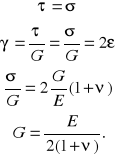
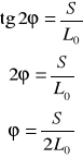
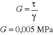
Moduł sprężystości postaciowej G, w przypadku odkształceń sprężystych i proporcjonalnych, definiuje się jako
![]()
a w przypadku odkształceń sprężystych i nieproporcjonalnych oraz dla praktycznych pomiarów G definiuje się jako
![]()
Teoretycznie ![]()
ale ponieważ ![]()
jest pochodną funkcji ![]()
stąd można te funkcje interpretować jako styczną do krzywej ![]()

3. wyprowadzenie zależności między G i E
![]()
wydłużenie ![]()
wydłużenie ![]()
![]()
![]()
z trójkąta A'OD'
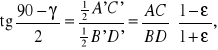
ponieważ AC = BD, to
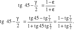
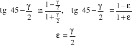
Korzystając z przybliżenia ![]()
otrzymujemy
4. Schemat aparatu lusterkowego Martensa do pomiaru kąta skręcenia
5. Schemat urządzenia do próby skręcania
6. Tabela pomiarów
Próbka poddana skręcaniu miała średnicę d0 = 8 mm. Wykonała ona 6 obrotów i uległa ukręceniu.
![]()
![]()
Ms
|
Ms |
n |
Φ |
Rs |
[kgN] |
[Nm] |
1 |
[rad] |
[MPa] |
220 |
22 |
2 |
6,28 |
- |
270 |
27 |
3 |
12,54 |
- |
280 |
28 |
4 |
18,84 |
- |
290 |
29 |
5 |
25,12 |
- |
300 |
30 |
6 |
31,4 |
- |
308 |
30,8 |
7 |
37,68 |
- |
310 |
31 |
8 |
43,86 |
- |
312 |
31,2 |
9 |
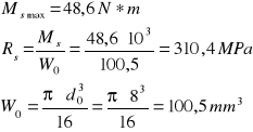
48,6 |
310,4 |
8. Przykłady obliczeń
Dane: 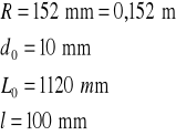
Ms dla F = 1 daN
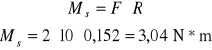
ϕ1 dla F = 1 daN
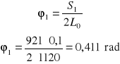
dla F = 1 daN
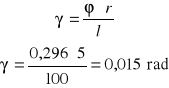
τ dla F = 1 daN
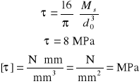
σ dla F = 1 daN
9. Wykresy
wykres histerezy sprężystej przy skręcaniu

wykres skręcania

1
1
γ
τ
Wyszukiwarka
Podobne podstrony:
Wyznaczanie odksztalcen w belkach zginanych, BUDOWNICTWO, INŻ, semestr 4, Mechanika budowli, Mechani
Wyznaczenie odksztace w belkach zginanych, BUDOWNICTWO, INŻ, semestr 4, Mechanika budowli, Mechanika
c61, BUDOWNICTWO, INŻ, semestr 4, Mechanika budowli, Mechanika Budowli 1, zadania
Mblab8~1, BUDOWNICTWO, INŻ, semestr 4, Mechanika budowli, Mechanika Budowli 2, przyklady
14, BUDOWNICTWO, INŻ, semestr 4, Mechanika budowli, Mechanika Budowli 1, zadania
Mechw2#, BUDOWNICTWO, INŻ, semestr 4, Mechanika budowli, Mechanika Budowli 2, przyklady
zginanie, BUDOWNICTWO, INŻ, semestr 4, Mechanika budowli, Mechanika Budowli 2, przyklady
Mechanika Budowli - Łuk Trójprzegubowy, BUDOWNICTWO, INŻ, semestr 4, Mechanika budowli, Mechanika Bu
Mechw10, BUDOWNICTWO, INŻ, semestr 4, Mechanika budowli, Mechanika Budowli 2, przyklady
Mbiwm4, BUDOWNICTWO, INŻ, semestr 4, Mechanika budowli, Mechanika Budowli 2, przyklady
Mb10, BUDOWNICTWO, INŻ, semestr 4, Mechanika budowli, Mechanika Budowli 2, przyklady
rodekzgin, BUDOWNICTWO, INŻ, semestr 4, Mechanika budowli, Mechanika Budowli 2, przyklady
spraw7betti2a, BUDOWNICTWO, INŻ, semestr 4, Mechanika budowli, Mechanika Budowli 1, zadania
Skręcanie swobodne pręta o przekroju (1), BUDOWNICTWO, INŻ, semestr 4, Mechanika budowli, Mechanika
Mechaniki Budowli, BUDOWNICTWO, INŻ, semestr 4, Mechanika budowli, Mechanika Budowli 1, zadania
więcej podobnych podstron