
DESIGN AND DEVELOPMENT OF MICRO TURBINE
A THESIS SUBMITTED IN PARTIAL FULFILLMENT OF THE
REQUIREMENTS FOR THE DEGREE OF
Bachelor of Technology
In
Mechanical Engineering
By
SIBASISH PATNAIK
and
ANKUR SACHDEV
Department of Mechanical Engineering
National Institute of Technology
Rourkela
2009

DESIGN AND DEVELOPMENT OF MICRO TURBINE
A THESIS SUBMITTED IN PARTIAL FULFILLMENT OF THE
REQUIREMENTS FOR THE DEGREE OF
Bachelor of Technology
In
Mechanical Engineering
By
SIBASISH PATNAIK
and
ANKUR SACHDEV
Under the guidance of
K. P. MAITY
Department of Mechanical Engineering
National Institute of Technology
Rourkela
2009

National Institute of Technology
Rourkela
CERTIFICATE
This is to certify that the thesis titled, “DESIGN AND DEVELOPMENT OF MICRO TURBINE”
submitted by Ankur Sachdev and Sibasish Patnaik in partial fulfillment of the requirements for the
award of Bachelor of Technology Degree in Mechanical Engineering at National Institute of
Technology, Rourkela (Deemed University) is an authentic work carried out by them under my
supervision and guidance.
To the best of my knowledge, the matter embodied in the thesis has not been submitted to any other
University / Institute for the award of any Degree or Diploma.
Date: Prof. K.P.Maity
Department of Mechanical Engineering
National Institute of Technology
Rourkela – 769008.

ACKNOWLEDGEMENT
We place on record and warmly acknowledge the continuous encouragement, invaluable
supervision, timely suggestions and inspired guidance offered by our guide Prof. K.P.Maity,
Department of Mechanical Engineering, National Institute of Technology, Rourkela, in bringing
this report to a successful completion. We consider ourselves fortunate to get a chance to work
under the guidance of such a dynamic personality.
We are grateful to Prof.P.Rath, Department of Mechanical Engineering, for building up our
fundamentals in Computational Fluid Dynamics which enabled us to carry out the project
successfully.
Last but not the least we thank our parents and the Almighty whose blessings are always there
with us.
Ankur Sachdev Sibasish Patnaik
10503042 10503072

Page | i
Contents
Contents..................................................................................................... i
List of Figures and Tables......................................................................... iii
Abstract...................................................................................................... iv
Chapter 1: Literature Review
1
Chapter 2: Gas Turbine
4
2.1 Gas Turbine
5
2.2
Types of Gas Turbine
5
2.3
Gas Turbine Cycle
5
2.4
Advantages of Gas Turbine
7
Chapter 3: Micro turbine
8
3.1 Micro turbine
9
3.2 Types of Microturbine
9
3.3 Characteristics of Microturbine
10
3.4 Advantages
10
3.5 Thermodynamic Heat Cycle for Micro turbine
11
3.6 Components of Micro turbine
12
3.7 Application
13
Chapter 4: Designing of Micro Turbine
14

Page | ii
4.1 Design of Turbine Blade
15
4.2 Design of Nozzle
19
4.3 Assembly
20
4.4 CFD Analysis
21
Chapter 5: Conclusion
25
References

Page | iii
List of Figures and Tables
Fig. 1.1:
Idealized Brayton Cycle
Fig. 1.2:
Microturbine based combined heat and power system
Fig. 1.3:
Blade Profile
Fig 1.4: Blade Profile (Different view)
Fig 1.5: Turbine Blade Passage
Fig 1.6: Nozzle Assembly
Fig.1.7: Turbine assembly
Fig.1.8: Turbine Assembly (Reverse view)
Fig 1.9: Velocity contours for steady state with laminar flow
Fig 1.10: Velocity contours for unsteady state with laminar flow
Table 1.1: Data for blade design

Page | iv
ABSTRACT:
Micro turbines are a relatively new type of combustion turbine that produces both heat and
electricity on a small scale. Micro turbines offer an efficient and clean solution to direct
mechanical drive markets such as compression and air-conditioning.
This report focuses on the
design and development of a micro turbine driven by compressed nitrogen gas. The available
literature regarding the design aspects of micro turbine were reviewed in detail. Gas turbine
cycle and operation of micro turbine was studied and reported. The turbine blades and nozzles
were designed with the help of Gambit software using a given set of cylindrical coordinates. The
turbine has a radial inlet and axial outlet. A proper meshing scheme was used to mesh the turbine
and nozzle assembly. CFD analysis was carried out by Fluent software to get the velocity vectors
using a set of suitable inputs.
Keywords: Gas turbine, turbine blade, nozzle, nitrogen

1 |
P a g e
Chapter 1
LITERATURE REVIEW

2 |
P a g e
Micro turbine is one of the important components in a micro gas turbine engine. Micro gas
turbine engine is a promising solution to provide high-density power source for micro systems. A
micro gas turbine engine consists of a radial inflow turbine, a centrifugal compressor and a
combustor. This thesis mainly deals with the design aspects of a micro turbine. Various journals
has been published on designing of various types of micro turbines. Exhaustive study has been
done on these papers and the major points have been highlighted here.
In the paper ―Design, fabrication and characterization of an air-driven micro turbine device‖ by
X. C. Shan, and Qide Zhang, development and investigations of a micro turbine device driven by
compressed air, which consists of three layers of silicon wafers and two layers of acrylic plates
has been presented. The key challenges to develop a successful high-speed turbine device are
geometry design and fabrication of micro blade profiles as well as air- bearings. The micro air
bearings have been designed, and a deep reactive ion etching (DRIE) process has been used for
fabricating micro journal bearings with high aspect ratio
―Design of turboexpander for cryogenic applications‖ by Subrata Kr. Ghosh , N. Seshaiah, R. K.
Sahoo, S. K. Sarangi focuses on design and development of turbo expander.The paper briefly
discuses the design methodology and the fabrication drawings for the whole system, which
includes the turbine wheel, nozzle, diffuser, shaft, brake compressor, two types of bearing, and
appropriate housing. With this method, it is possible to design a turbo expander for any other
fluid since the fluid properties are properly taken care of in the relevant equations of the design
procedure.
A simple method sufficient for the design of a high efficiency expansion turbine is outlined by
Kun et. al. A study was initiated in 1979 to survey operating plants and generate the cost factors
relating to turbine by Kun & Sentz. Sixsmith et. al. in collaboration with Goddard Space Flight
Centre of NASA, developed miniature turbines for Brayton Cycle cry coolers. They have
developed of a turbine, 1.5 mm in diameter rotating at a speed of approximately one million rpm.
Yang et. al developed a two stage miniature expansion turbine made for an 1.5 L/hr helium
liquefier at the Cryogenic Engineering Laboratory of the Chinese Academy of Sciences. The
turbines rotated at more than 500,000 rpm. The design of a small, high speed turbo expander was
taken up by the National Bureau of Standards (NBS) USA. The first expander operated at

3 |
P a g e
600,000 rpm in externally pressurized gas bearings. The turbo expander developed by Kate et. al
was with variable flow capacity mechanism (an adjustable turbine), which had the capacity of
controlling the refrigerating power by using the variable nozzle vane height.
In another paper on ―A micro turbine device with enhanced micro air bearings by ―X. C. Shan ,
Q. D. Zhang , Y. F. Sun and R. Maeda design, fabrication and testing of a silicon-based micro
turbine device, which is driven by compressed air has been shown. The thrust air bearings are
utilized for supporting the rotor from both its top- and bottom- sides.
India has also started devoting attention to this field of research work and significant progress
has been made during the past two decades. In CMERI Durgapur, Jadeja et. al developed an
inward flow radial turbine supported on gas bearings for cryogenic plants. The device gave
stable rotation at about 40,000 rpm. Another programme at IIT Kharagpur developed a turbo
expander unit by using aerostatic thrust and journal bearings which had a working speed up to
80,000 rpm. The detailed summary of technical features of the cryogenic turbo expander
developed in various laboratories has been given in the PhD dissertation of Ghosh. Recently
Cryogenic Technology Division, BARC developed Helium refrigerator capable of producing 1
kW at 20K temperature.

4 |
P a g e
Chapter 2
GAS TURBINE

5 |
P a g e
2.1 Gas Turbine
A gas turbine is a rotating engine that extracts energy from a flow of combustion gases that result
from the ignition of compressed air and a fuel (either a gas or liquid, most commonly natural
gas). It has an upstream compressor module coupled to a downstream turbine module, and a
combustion chamber(s) module (with igniter[s]) in between.
Energy is added to the gas stream in the combustor, where air is mixed with fuel and ignited.
Combustion increases the temperature, velocity, and volume of the gas flow. This is directed
through a nozzle over the turbine’s blades, spinning the turbine and powering the compressor.
Energy is extracted in the form of shaft power, compressed air, and thrust, in any combination,
and used to power aircraft, trains, ships, generators, and even tanks.
2.2 Types of Gas Turbine
There are different types of gas turbines. Some of them are named below:
1. Aero derivatives and jet engines
2. Amateur gas turbines
3. Industrial gas turbines for electrical generation
4. Radial gas turbines
5. Scale jet engines
6. Micro turbines
The main focus of this paper is the design aspects of micro turbine.
2.3 Gas Turbine Cycle
The simplest gas turbine follows the Brayton cycle (Figure 1.1). In a closed cycle (i.e., the
working fluid is not released to the atmosphere), air is compressed isentropically, combustion
occurs at constant pressure, and expansion over the turbine occurs isentropically back to the
starting pressure. As with all heat engine cycles, higher combustion temperature (the common
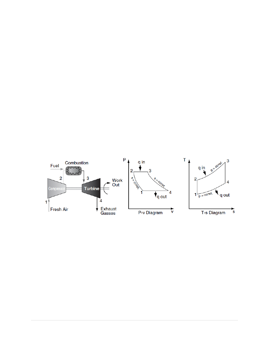
6 |
P a g e
industry reference is turbine inlet temperature) means greater efficiency. The limiting factor is
the ability of the steel, ceramic, or other materials that make up the engine to withstand heat and
pressure. Considerable design/manufacturing engineering goes into keeping the turbine parts
cool. Most turbines also try to recover exhaust heat, which otherwise is wasted energy.
Recuperators are heat exchangers that pass exhaust heat to the compressed air, prior to
combustion. Combined-cycle designs pass waste heat to steam turbine systems, and combined
heat and power (i.e., cogeneration) uses waste heat for hot water production. Mechanically, gas
turbines can be considerably less complex than internal combustion piston engines. Simple
turbines might have one moving part: the shaft/compressor/ turbine/alternator-rotor assembly,
not counting the fuel system. More sophisticated turbines may have multiple shafts (spools),
hundreds of turbine blades, movable stator blades, and a vast system of complex piping,
combustors, and heat exchangers.
Figure 1.1- Idealized Brayton Cycle
The largest gas turbines operate at 3000 (50 hertz [Hz], European and Asian power supply) or
3600 (60 Hz, U.S. power supply) RPM to match the AC power grid. They require their own
building and several more to house support and auxiliary equipment, such as cooling towers.
Smaller turbines, with fewer compressor/turbine stages, spin faster. Jet engines operate around
10,000 RPM and micro turbines around 100,000 RPM. Thrust bearings and journal bearings are
a critical part of the design. Traditionally, they have been hydrodynamic oil bearings or oil-
cooled ball bearings.

7 |
P a g e
2.4 Advantages of Gas Turbine
1. Very high power-to-weight ratio, compared to reciprocating engines.
2. Smaller than most reciprocating engines of the same power rating.
3. Moves in one direction only, with far less vibration than a reciprocating engine.
4. Fewer moving parts than reciprocating engines.
5. Low operating pressures.
6. High operation speeds.
7. Low lubricating oil cost and consumption.

8 |
P a g e
Chapter 3
MICRO TURBINE

9 |
P a g e
3.1 Micro turbine
Micro turbines are small combustion turbines with outputs of 25 kW to 500 kW. They evolved
from automotive and truck turbochargers, auxiliary power units (APUs) for airplanes, and small
jet engines.
Micro turbines are a relatively new distributed generation technology being used for
stationary energy generation applications. They are a type of combustion turbine that produces
both heat and electricity on a relatively small scale.
A micro gas turbine engine consists of a radial inflow turbine, a centrifugal compressor and a
combustor. The micro turbine is one of the critical components in a micro gas turbine engine,
since it is used for outputting power as well as for rotating the compressor. Micro turbines are
becoming widespread for distributed power and combined heat and power applications. They are
one of the most promising technologies for powering hybrid electric vehicles. They range from
hand held units producing less than a kilowatt, to commercial sized systems that produce tens or
hundreds of kilowatts.
Part of their success is due to advances in electronics, which allows unattended operation and
interfacing with the commercial power grid. Electronic power switching technology eliminates
the need for the generator to be synchronized with the power grid. This allows the generator to
be integrated with the turbine shaft, and to double as the starter motor.
They accept most commercial fuels, such as gasoline, natural gas, propane, diesel, and kerosene
as well as renewable fuels such as E85, biodiesel and biogas.
3.2 Types of Micro turbine
Micro turbines are classified by the physical arrangement of the component parts: single shaft or
two-shaft, simple cycle, or recuperated, inter-cooled, and reheat. The machines generally rotate
over 40,000 revolutions per minute. The bearing selection—oil or air—is dependent on usage. A
single shaft micro turbine with high rotating speeds of 90,000 to 120,000 revolutions per minute
is the more common design, as it is simpler and less expensive to build. Conversely, the split

10 |
P a g e
shaft is necessary for machine drive applications, which does not require an inverter to change
the frequency of the AC power.
3.3 Characteristics of Micro turbine
Some of the primary characteristics for micro turbines include:
Distributed generation—stand-alone, on-site applications remote from power grids
Quality power and reliability—reduced frequency variations, voltage transients, surges,
dips, or other disruptions
Stand-by power—used in the event of an outage, as a back-up to the electric grid
Peak shaving—the use of micro turbines during times when electric use and demand
charges are high
Boost power—boost localized generation capacity and on more remote grids
Low-cost energy—the use of micro turbines as base load or primary power that is less
expensive to produce locally than it is to purchase from the electric utility
Combined heat and power (cogeneration)—increases the efficiency of on-site power
generation by using the waste heat for existing thermal process.
3.4 Advantages
Micro turbine systems have many advantages over reciprocating engine generators, such as
higher power density (with respect to footprint and weight), extremely low emissions and few, or
just one, moving part. Those designed with foil bearings and air-cooling operate without oil,
coolants or other hazardous materials. Micro turbines also have the advantage of having the
majority of their waste heat contained in their relatively high temperature exhaust, whereas the
waste heat of reciprocating engines is split between its exhaust and cooling system. However,
reciprocating engine generators are quicker to respond to changes in output power requirement
and are usually slightly more efficient, although the efficiency of micro turbines is increasing.
Micro turbines also lose more efficiency at low power levels than reciprocating engines.

11 |
P a g e
Micro turbines offer several potential advantages compared to other technologies for small-scale
power generation, including: a small number of moving parts, compact size, lightweight, greater
efficiency, lower emissions, lower electricity costs, and opportunities to utilize waste fuels.
Waste heat recovery can also be used with these systems to achieve efficiencies greater than
80%. Because of their small size, relatively low capital costs, expected low operations and
maintenance costs, and automatic electronic control, micro turbines are expected to capture a
significant share of the distributed generation market. In addition, micro turbines offer an
efficient and clean solution to direct mechanical drive markets such as compression and air-
conditioning.
3.5 Thermodynamic Heat Cycle
In principle, micro turbines and larger gas turbines operate on the same thermodynamic heat
cycle, the Brayton cycle. In this cycle, atmospheric air is compressed, heated at constant
pressure, and then expanded, with the excess power produced by the expander (also called the
turbine) consumed by the compressor used to generate electricity. The power produced by an
expansion turbine and consumed by a compressor is proportional to the absolute temperature of
the gas passing through those devices. Higher expander inlet temperature and pressure ratios
result in higher efficiency and specific power. Higher pressure ratios increase efficiency and
specific power until an optimum pressure ratio is achieved, beyond which efficiency and specific
power decrease. The optimum pressure ratio is considerably lower when a recuperator is used.
Consequently, for good power and efficiency, it is advantageous to operate the expansion turbine
at the highest practical inlet temperature consistent with economic turbine blade materials and to
operate the compressor with inlet air at the lowest temperature possible. The general trend in gas
turbine advancement has been toward a combination of higher temperatures and pressures.
However, micro turbine inlet temperatures are generally limited to 1750°F or below to enable the
use of relatively inexpensive materials for the turbine wheel and recuperator. For recuperated
turbines, the optimum pressure ratio for best efficiency is usually less than 4:1.

12 |
P a g e
3.6 Components of Micro turbine
Micro turbines are very small gas turbines (30 to 400 kilowatts [kW]) that usually have an
internal heat-recovery heat exchanger (called a recuperator) to improve electric efficiency. In
typical micro turbines, the cycle is similar to that of a conventional gas turbine. It consists of the
following processes:
● Inlet air is compressed in a radial (centrifugal) compressor, then
● Preheated in the recuperator using heat from the turbine exhaust.
● Heated air from the recuperator is mixed with fuel in the combustor and burned.
The hot combustion gas is then expanded in one or more turbine sections, which produces
rotating mechanical power to drive the compressor and the electric generator. The recuperator
efficiency is the key to whether a particular micro turbine is economically viable. By
comparison, in a conventional gas turbine, the gas flow path is as follows: compressed air from
the compressor (more air mass can be ―introduced‖ by inter-cooling) is burned with fuel.
Gaseous products expand through the turbine section (where more power can be extracted by
reheating the gaseous products). Exhaust gases can provide waste heat recovery or cogeneration
potential, as those gases may produce steam to drive a steam turbine, may be led into a
greenhouse system, or may optimize thermal efficiency by some other means. Wit hout waste
heat recovery or cogeneration of some sort, a gas turbine is said to operate in ―simple cycle‖
mode. With the addition of a boiler (to get steam from waste heat recovery) and a steam turbine,
the gas turbine package is said to operate as a ―combined cycle.‖ However, most micro turbines,
to be financially viable, have a recuperator (to recover waste heat). This is not quite a simple
cycle, but the micro turbine can be said to operate ―solo‖ in power-only applications. Frequently,
micro turbines are used to extract heat as a product. This then would be called combined heat and
power (CHP) applications. In single-shaft micro turbines, a single expansion turbine turns both
the compressor and the generator. Two-shaft models use one turbine to drive the compressor and
a second turbine to drive the generator, with exhaust from the compressor turbine powering the
generator turbine. The power turbine’s exhaust is then used in the recuperator to preheat the air
from the compressor.
13 |
P a g e
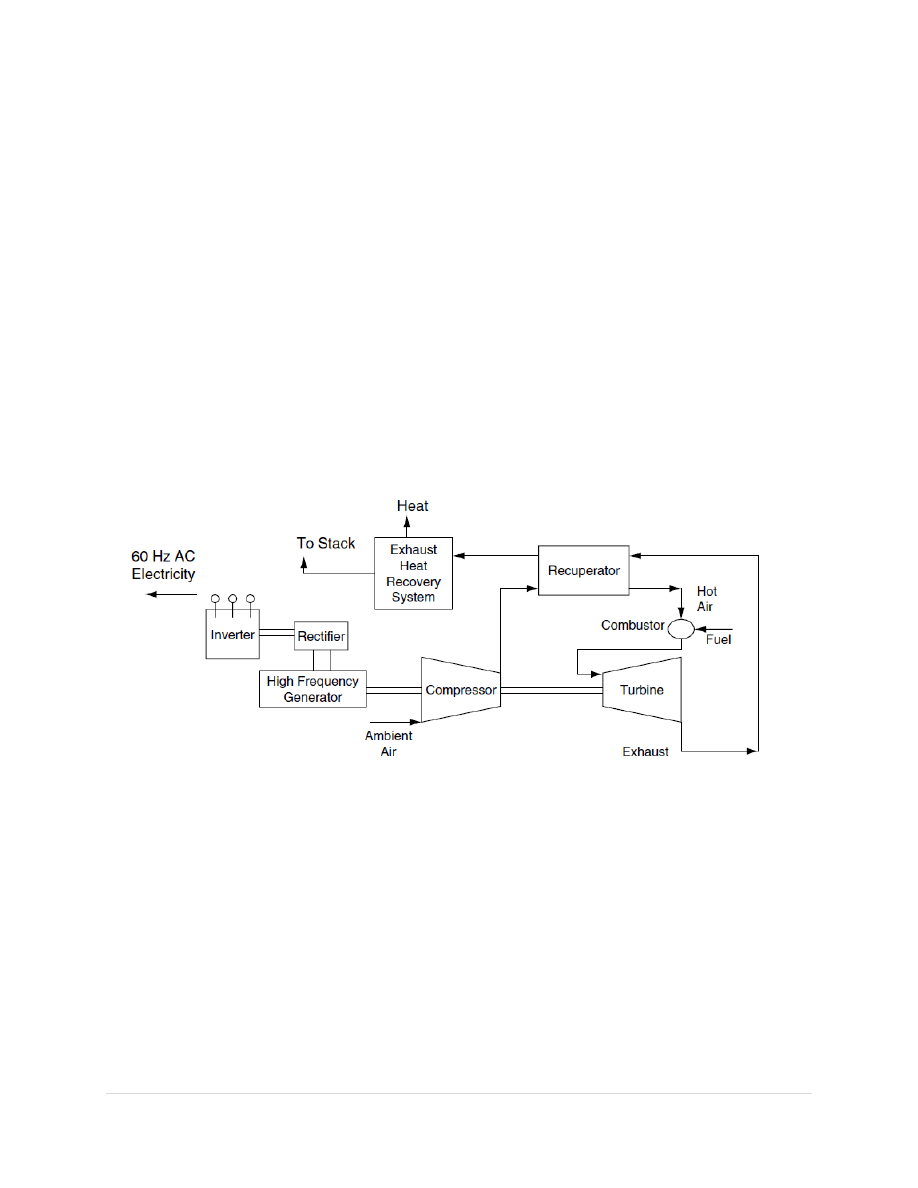
The basic components of a micro turbine are the compressor, turbine, generator, and recuperator
(Figure 2-1). The heart of the micro turbine is the compressor-turbine package, which is most
commonly mounted on a single shaft along with the electric generator. The single shaft is
supported by two (or more) high-speed bearings. Because single-shaft turbines have only one
moving shaft, they have the potential for lower maintenance and higher reliability than turbines
with two or more shafts. There are also two-shaft versions of the micro turbine, in which the
turbine on the first shaft only drives the compressor while a second power turbine on a second
shaft drives a gearbox and conventional electric generator producing 60 or 50 Hz of power.
Moderate- to large-sized gas turbines use multistage axial flow compressors and turbines, in
which the gas flows parallel to the axis of the shaft and then is compressed and expanded in
multiple stages. Most current micro turbines are based on single-stage radial flow compressors
and either single- or double-stage turbines.
Figure 1.2-Microturbine based combined heat and power system
3.7 Applications
Micro turbines can be used for stand-by power, power quality and reliability, peak shaving, and
cogeneration applications. In addition, because micro turbines are being developed to utilize a
variety of fuels, they are being used for resource recovery and landfill gas applications. Micro
turbines are well suited for small commercial building establishments such as: restaurants,
hotels/motels, small offices, retail stores, and many others.

14 |
P a g e
Chapter 4
DESIGNING OF MICRO TURBINE

15 |
P a g e
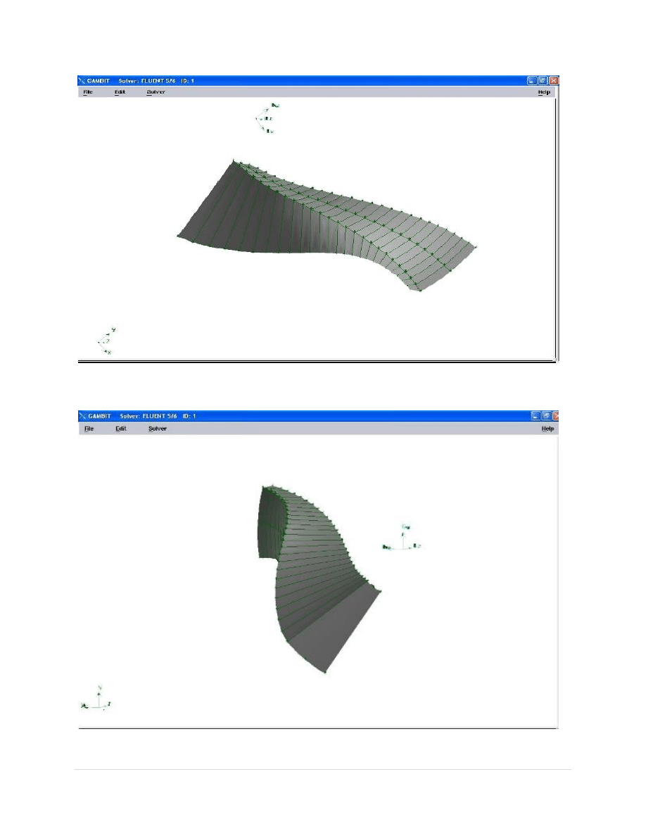
4.1 Design of Turbine Blade
The modelling of the blades and nozzles was done using Gambit 2.3.16 software. Gambit is a
software package designed to help analysts and designers build and mesh models for
computational fluid dynamics (CFD) and other scientific applications. It includes both geometry
modelling and mesh generation tools for structured, unstructured and hybrid meshing.
The main features of the geometry i.e. the blades, nozzles, diffuser were created using Gambit.
They were then assembled to construct the 3-D geometry.
A method of computing blade profiles has been worked out by H.Hasselgruber(1958).The rotor
blade geometry comprises of a series of three dimensional streamlines which are determined
from a series of mean line distributions and are used to form the rotor blade surface. The
coordinates needed for the purpose were obtained from the available literature.
Table 1.1 shows qualitatively the computed hub and tip streamlines as well as the resulting
stream surface. These data are used to create NURBS (Non-Uniform Rational B Splines) for
solid models in Gambit. A ruled surface is created by joining the hub and tip streamlines with a
set of tie lines. The surface so generated is considered as the mean surface within a blade. The
suction and pressure surfaces of two adjacent channels are computed by translating the mean
surface in the +ve and -ve θ directions through half the blade thickness. Coordinates of all the
blade surfaces are computed by further rotating the pair of surfaces over an angle 2π / Z, i.e.
51.43
o
for Z = 7.
The turbine wheel is of radial or mixed flow geometry, i.e. the flow enters the wheel radially and
exits axially. The blade passage has a profile of a three dimensional converging duct, changing
from purely radial to an axial-tangential direction. Work is extracted as the process gas
undergoes expansion with corresponding drop in static temperature.

16 |
P a g e
TIP CAMBERLINE
HUB CAMBERLINE
z(mm)
r(mm)
phi(deg)
z(mm)
r(mm)
phi(deg)
-0.4775
2.2615
0
0
0.7915
0
-0.35975
2.28025
5.502
0.1065
0.84575
5.502
-0.2375
2.28225
10.61
0.20875
0.9165
10.61
-0.11725
2.2835
15.347
0.31275
0.9885
15.347
0.0005
2.28575
19.732
0.41875
1.06075
19.732
0.11575
2.2895
23.786
0.52675
1.13325
23.786
0.2285
2.29525
27.524
0.6365
1.2065
27.524
0.33825
2.30325
30.961
0.7475
1.28125
30.961
0.4455
2.314
34.111
0.85925
1.358
34.111
0.55025
2.32775
36.987
0.971
1.438
36.987
0.65175
2.34525
39.602
1.082
1.52125
39.602
0.751748
2.3665
41.966
1.1915
1.609
41.966
0.84825
2.3925
44.091
1.29825
1.7015
44.091
0.943275
2.42325
45.989
1.4015
1.799
45.989
1.0275
2.45975
47.672
1.50025
1.902
47.672
1.1175
2.50225
49.15
1.593
2.0105
49.15
1.2075
2.5515
50.435
1.679
2.124
50.435
1.2825
2.60775
51.54
1.757
2.24225
51.54
1.3575
2.6715
52.475
1.82625
2.36425
52.475
1.4325
2.74475
53.253
1.8865
2.4895
53.253
1.5
2.8205
53.891
1.93725
2.617
53.891
1.55775
2.906
54.38
1.979
2.7455
54.38
1.6095
2.9975
54.752
2.012
2.86725
54.752
1.65375
3.09475
55.007
2.037
3.00225
55.007
1.69125
3.19675
55.154
2.05475
3.1295
55.154
1.72275
3.279
55.202
2.06675
3.279
55.202
Table 1.1- Data for blade design
where,
z = axial length
r = radius
phi = angle of deflection measured in clockwise direction
17 |
P a g e
F
IG 1.3-Blade Profile
F
IG 1.4-Blade Profile (Different view)
18 |
P a g e
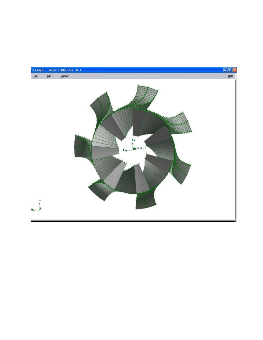
The obtained blade profile is then rotated about z-axis by using the copy option in Gambit to
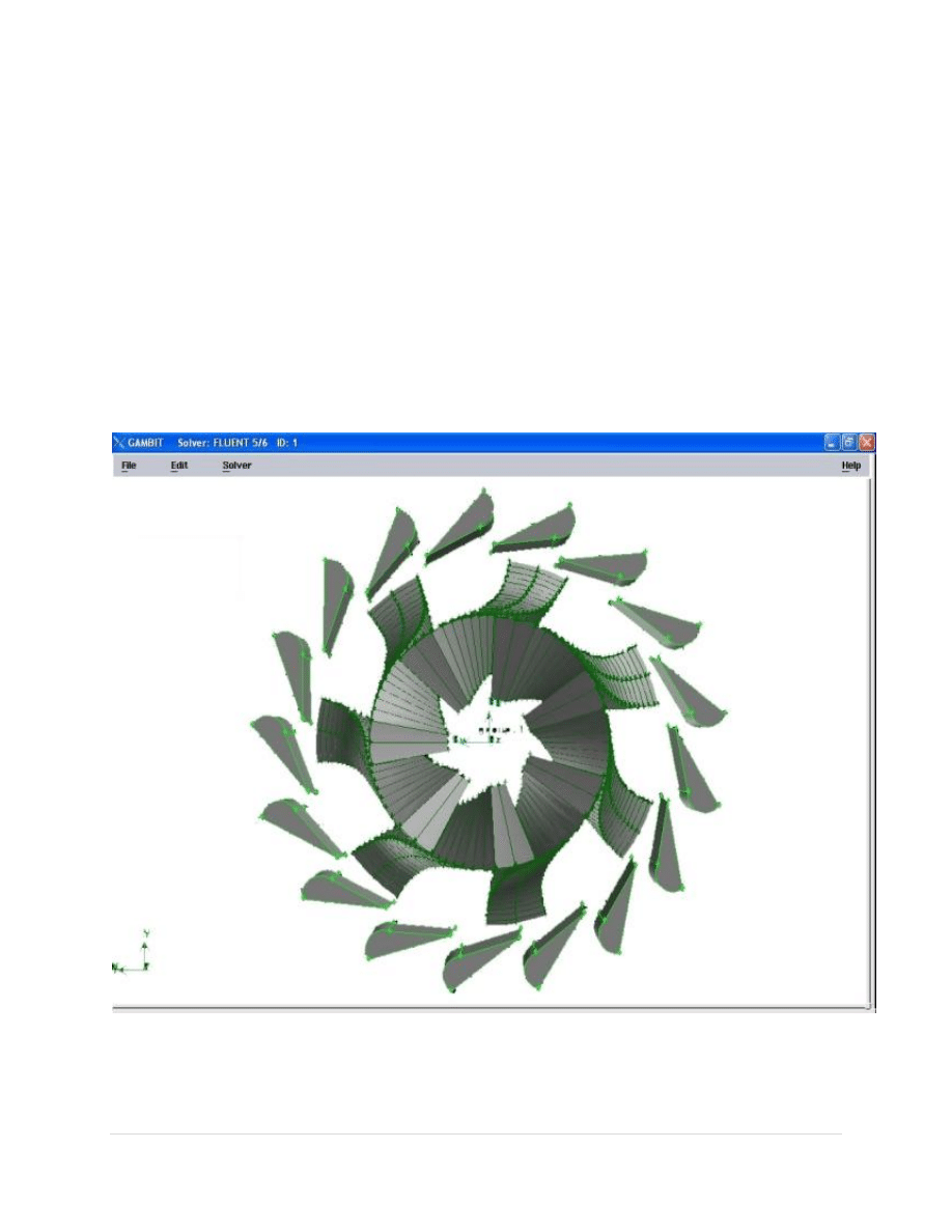
create the turbine blade assembly. The blades are rotated by 2π / Z, i.e. 51.43
o
for Z = 7.
FIG 1.5-Turbine Blade Passage

19 |
P a g e
4.2 Design of Nozzle
A set of static nozzles must be provided around the turbine wheel to generate the required inlet
velocity and swirl. The working fluid accelerates through the converging passages of the nozzles.
Pressure energy is transformed into kinetic energy, leading to a reduction in static temperature.
The high velocity fluid streams impinge on the rotor blades, imparting force to the rotor and
creating torque. The nozzles and the rotor blades are so aligned as to eliminate sudden changes in
flow direction and consequent loss of energy.
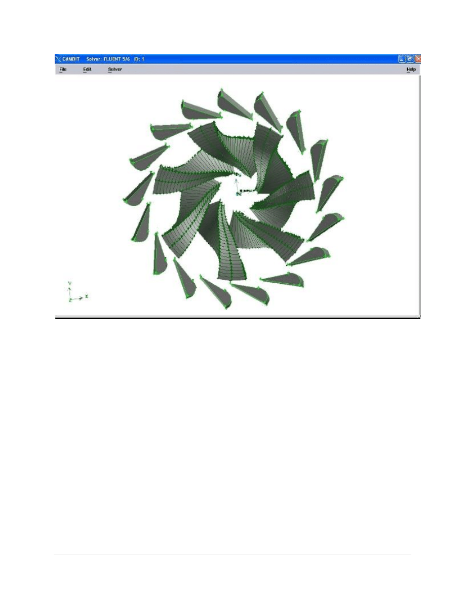
Kun, L .C. and Sentz, R. N.(1985) proposed that the number of nozzle blades is normally
dictated by mechanical design consideration, particularly to ensure that nozzle discharge does
not excite some natural frequency of the impeller. The number of blades in the nozzle and that in
the wheel should be mutually prime in order to raise this excitation frequency well beyond the
operating speed and to reduce the overall magnitude of the peak force. The number of nozzle
blades has been taken as 17 for 7 blades in the turbine wheel. The nozzle was designed in
Gambit using data from available literature. The obtained nozzle profile was then rotated about
z-axis over an angle 21.18
o
to create the complete nozzle assembly.
FIG 1.6-Nozzle Assembly
20 |
P a g e
4.3 Assembly
The turbine blades and nozzles were then assembled to give the complete turbine profile. The
high-pressure process gas enters the turbine through the converging passages of the nozzles.
Pressure energy is transformed into kinetic energy, leading to a reduction in static temperature.
The high velocity fluid streams impinge on the rotor blades, imparting force to the rotor and
creating torque. The turbine wheel is of radial or mixed flow geometry, i.e. the flow enters the
wheel radially and exits axially. Work is extracted as the process gas undergoes expansion with
corresponding drop in static temperature.
FIG.1.7-Turbine assembly
21 |
P a g e
Fig.1.8 Turbine Assembly (Reverse view)
4.4 CFD Analysis
The CFD analysis has been carried out by the help of Fluent 6.2 software. Fluent enables
engineers and designers to simulate fluid flow, heat and mass transfer, and a host of related
phenomena involving turbulent, reacting, and multiphase flow. The broad physical modelling
capabilities of Fluent have been applied to industrial applications ranging from airflow over an
aircraft wing to combustion in a furnace, from bubble columns to glass production, from blood
flow to semiconductor manufacturing, from clean room design to wastewater treatment plants.
The ability of the software to model in-cylinder engines, aero acoustics, turbo machinery, and
multiphase systems has served to broaden its reach.

22 |
P a g e
Advanced solver technology provides fast, accurate CFD results, flexible moving and deforming
meshes, and superior parallel scalability. User-defined functions allow the implementation of
new user models and the extensive customization of existing ones. Fluent’s interactive solver set-
up, solution, and post-processing make it easy to pause a calculation, examine results with
integrated post-processing, change any setting, and then continue the calculation within a single
application.
Fluent is written in the C computer language and makes full use of the flexibility and power
offered by the language. Consequently, true dynamic memory allocation, efficient data
structures, and flexible solver control are all possible. All functions required to compute a
solution and display the results are accessible in Fluent through an interactive, menu-driven
interface.
The analysis of a turbine with similar profile has been carried out in a previous literature. The
procedure and results of that analysis are reported here.
The material selected was nitrogen gas.
The properties of Nitrogen used are as follows:
Density = 1.138 kg/m3
Cp (specific heat capacity) = 1040.67 J/kg K
Thermal conductivity = 0.0242 W/m K
Viscosity = 1.663 x 10⁻⁵ kg/m s
The analysis was done at atmospheric pressure condition and with given conditions. The nozzle
inlet was defined as the mass-flow-inlet with a mass flow rate of 0.0606 kg/s. The total
temperature was taken to be 120K and initial Gauge pressure was taken as 5 bar. The mixing
plane model was used. Two mixing planes were needed, one at the interface between the
pressure outlet of the upstream nozzle outlet region and the pressure inlet at the adjacent face of
the blades passage region. It was defined as radial mixing plane geometry. Similarly, the second
mixing plane was defined at the pressure outlet of blades passage and the pressure inlet to the
downstream diffuser inlet region. It was defined as axial mixing plane geometry. For the mixing
23 |
P a g e
planes as defined earlier, the boundary conditions were set to default. The z-axis was selected as
the rotation axis and moving mesh type was selected with a rotational speed of 10400 rad/sec.
The diffuser outlet was defined as pressure outlet. The backflow temperature was set to 80K and
the pressure was set to default value of 0 bar.
The steady state as well as unsteady state analysis was carried out in Fluent. The turbulent flow
analysis was done using k-epsilon method. The Pressure-velocity coupling was done using
SIMPLE algorithm. The SIMPLE algorithm uses a relationship between velocity and pressure
corrections to enforce mass conservation and to obtain the pressure field. The second order
upwind scheme, PRESTO scheme and second order upwind scheme was used for momentum,
pressure and energy equations.
The suitable under relaxation factors were given, depending upon the nature of the model
selected. The residuals were plotted. Initialization was done and the solution was subjected to
iterations till convergence was obtained. The different contours of pressure and velocity, and the
velocity vectors were plotted and the results were analyzed for the different cases.
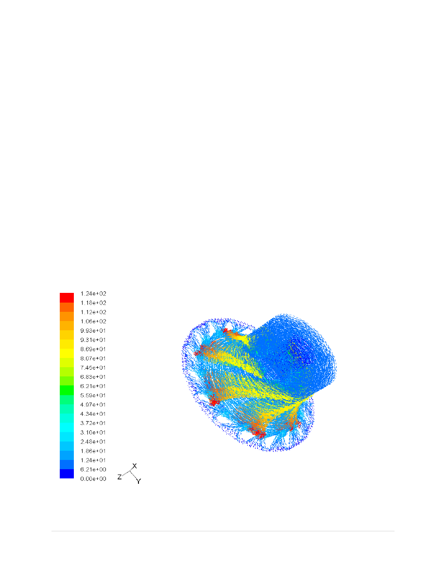
FIG 1.9- Velocity contours for steady state with laminar flow
24 |
P a g e
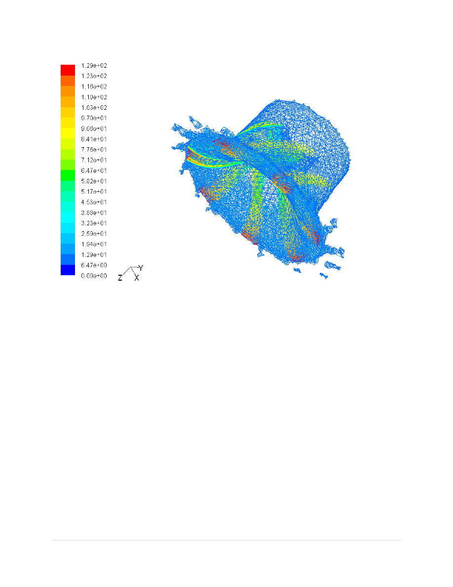
FIG 1.10- Velocity contours for unsteady state with laminar flow

25 |
P a g e
Chapter 5
CONCLUSION

26 |
P a g e
The work presented in the report is an attempt at designing a micro turbine of a given dimension.
Extensive literature review was carried out to study the various aspects and applications of micro
turbines. A suitable design procedure was chosen from the available methods to design the
turbine blades and nozzles. Modelling of blade profile was done using a set of given co-
ordinates. Gambit was used for creation of a single blade and then they were assembled to give
the complete turbine wheel. CFD analysis of a turbine with similar profile has also been reported
from an available literature.
Micro turbines are relatively new in the market and are attracting wide attention due to their
varied applications. Development of a sophisticated engineering product like micro turbine is a
continuous process. A lot of work is yet to be done on the design aspects before the micro
turbine can be readied for market consumption. The design procedure has to take into various
other parameters to make it suitable for practical applications. Also, manufacturing of such
complex shapes of minute size is another ongoing research work. Further research into the
design and manufacture process would result in production of even better micro turbines.

27 |
P a g e
REFERENCE:
1. Experimental and Computational Studies on Cryogenic Turbo expander – S. K. Ghosh
and Sarangi
2. Design, fabrication and characterization of an air-driven micro turbine device-
X. C. Shan, Qide Zhang and Yaofeng Sun, Zhenfeng Wang
3. Experimental simulation on the integration of solid oxide fuel cell and micro-turbine
generation system-by Wei-Hsiang Lai , Chi-An Hsiao , Chien-Hsiung Lee , Yau-Pin
Chyou
b
, Yu-Ching Tsai
4. Laser Profiling of 3-D Micro turbine Blades-by Andrew S. Holmes, Mark E. Heaton,
Guodong Hong, Keith R. Pullen and Phil T. Rumsby
5. Experimental and simulation analysis of micro turbines- by S. M. Flockhart and R.S.
Dhariwal
6. ―Analytical and Experimental Studies on Turboexpander‖ - Ghosh, P and Sarangi, IIT
Kharagpur (2002)
7. A micro turbine device with enhanced micro air bearings-by X. C. Shan , Q. D. Zhang ,
Y. F. Sun and R. Maed
8. High efficiency expansion turbines in air separation and liquefaction plants International
Conference on Production and Purification of Coal Gas & Separation of Air, Kun, L .C.
and Sentz, R. N. , Beijing, China (1985), 1-21
9. Hammerstein-model-based predictive control of micro-turbines- by Francisco Jurado

28 |
P a g e
11. Hydraulics an Fluid Mechanics- by Modi and Seth
12. B-Fluid Dynamics and Heat Transfer in Turbo machinery - Laxminarayana
13. Fluid Mechanics and Thermodynamics of Turbo machinery - Dixon, S. L.
14. V Numerical Heat Transfer and Fluid Flow - Patankar Suhas
15. Stromungsgerechte gestaltung der laufrader von radialkompressoren mit axialem
laufradeintrict Konstruction - H. Hasselgruber (1958), 10(1) 22(in German)\
16
.
- Bernard F. Kolanowski (2004)
Wyszukiwarka
Podobne podstrony:
Advanced Methods for Development of Wind turbine models for control designe
Development of BBM turbine
Development of wind turbine control algorithms for industrial use
Design and implementation of Psychoacoustics Equalizer for Infotainment
FIDE Trainers Surveys 2012 08 31 Uwe Bönsch The recognition, fostering and development of chess tale
[architecture ebook] Design And Construction Of Japanese Gardens
Design and construction of three phase transformer for a 1 kW multi level converter
Design and Performance of the OpenBSD Statefull Packet Filter Slides
Design and manufacturing of plastic
Wójcik, Marcin; Suliborski, Andrzej The Origin And Development Of Social Geography In Poland, With
Emotion Work as a Source of Stress The Concept and Development of an Instrument
Ando Acoustical Design And Measurement Of A Circular Hall, Improving A Spatial Factor At Each Seat
Invention And Development Of The Flag Antenna
Center Temperament and Development of Conduct Disorders
Design and Simulation of a Stand alone Wind Diesel Generator with a Flywheel
więcej podobnych podstron