Air-Conditioners
PKA-RP·FAL (2)
PKH-P·FALH
English
Deutsch
Français
Nederlands
Español
Italiano
∂ÏÏËÓÈο
Português
Dansk
Svenska
Türkçe
Русский
INSTALLATION MANUAL
For safe and correct use, read this manual and the outdoor unit installation manual thoroughly before installing
the air-conditioner unit.
FOR INSTALLER
INSTALLATIONSHANDBUCH
Aus Sicherheitsgründen und zur richtigen Anwendung vor Installation der Klimaanlage die vorliegende Bedie-
nungsanleitung und das Installationshandbuch gründlich durchlesen.
MANUEL D’INSTALLATION
Avant d’installer le climatiseur, lire attentivement ce manuel, ainsi que le manuel d’installation de l’appareil
extérieur pour une utilisation sûre et correct.
INSTALLATIONSMANUAL
Läs bruksanvisningen och utomhusenhetens installationshandbok noga innan luftkonditioneringen installeras så
att den används på ett säkert och korrekt sätt.
INSTALLATIEHANDLEIDING
Lees deze handleiding en de installatiehandleiding van het buitenapparaat zorgvuldig door voordat u met het
installeren van de airconditioner begint.
MANUALE DI INSTALLAZIONE
Per un uso sicuro e corretto, prima di installare il condizionatore d’aria leggere attentamente il presente
manuale ed il manuale d’installazione dell’unità esterna.
MANUAL DE INSTALACIÓN
Para un uso seguro y correcto, lea detalladamente este manual de instalación antes de montar la unidad de
aire acondicionado.
E°XEIPI¢IO O¢H°IøN E°KATA™TA™H™
°È· ÛˆÛÙ‹ Î·È ·ÛÊ·Ï‹ ¯Ú‹ÛË, ‰È·‚¿ÛÙ ÚÔÛÂÎÙÈο ·˘Ùfi ÙÔ ÂÁ¯ÂÈÚ›‰ÈÔ, ηıÒ˜ Î·È ÙÔ ÂÁ¯ÂÈÚ›‰ÈÔ
ÂÁηٿÛÙ·Û˘ Ù˘ Â͈ÙÂÚÈ΋˜ ÌÔÓ¿‰·˜, ÚÈÓ ·fi ÙËÓ ÂÁηٿÛÙ·ÛË Ù˘ ÌÔÓ¿‰·˜ ÎÏÈÌ·ÙÈÛÙÈÎÔ‡.
MANUAL DE INSTALAÇÃO
Para uma utilização segura e correcta, leia atentamente este manual e o manual de instalação da unidade
exterior antes de instalar o aparelho de ar condicionado.
INSTALLATIONSMANUAL
Læs af sikkerhedshensyn denne manual samt manualen til installation af udendørsenheden grundigt, før du
installerer klimaanlægget.
MONTAJ ELK‹TABI
Emniyetli ve do¤ru kullanım için, klima cihazını monte etmeden önce bu kılavuzu ve dıfl ünite montaj kılavuzunu
tamamıyla okuyun.
РУКОВОДСТВО ПО УСТАНОВКЕ
Для обеспечения безопасной и надлежащей эксплуатации внимательно прочтите данное руководство и
руководство по установке наружного прибора перед установкой кондиционера.
FÜR INSTALLATEURE
POUR L’INSTALLATEUR
FÖR INSTALLATÖREN
VOOR DE INSTALLATEUR
PER L’INSTALLATORE
PARA EL INSTALADOR
PARA O INSTALADOR
TIL INSTALLATØREN
°π∞ ∞À∆√¡ ¶√À ∫∞¡∂π ∆∏¡ ∂°∫∞∆∞™∆∞™∏
MONTÖR ‹Ç‹N
ДЛЯ УСТАНОВИТЕЛЯ
2
s Before installing the unit, make sure you read all the “Safety precau-
tions”.
s Please report to your supply authority or obtain their consent before
connecting this equipment to the power supply system.
Warning:
Describes precautions that must be observed to prevent danger of injury or
death to the user.
Caution:
Describes precautions that must be observed to prevent damage to the unit.
1.2. Before installation or relocation
Caution:
• Be extremely careful when transporting the units. Two or more persons are
needed to handle the unit, as it weighs 20 kg or more. Do not grasp the
packaging bands. Wear protective gloves as you can injure your hands on
the fins or other parts.
• Be sure to safely dispose of the packaging materials. Packaging materials,
such as nails and other metal or wooden parts may cause stabs or other
injuries.
Contents
Warning:
• Ask a dealer or an authorized technician to install the unit.
• For installation work, follow the instructions in the Installation Manual and
use tools and pipe components specifically made for use with refrigerant
specified in the outdoor unit installation manual.
• The unit must be installed according to the instructions in order to minimize
the risk of damage from earthquakes, typhoons, or strong winds. An incor-
rectly installed unit may fall down and cause damage or injuries.
• The unit must be securely installed on a structure that can sustain its weight.
• If the air conditioner is installed in a small room, measures must be taken to
prevent the refrigerant concentration in the room from exceeding the safety
limit in the event of refrigerant leakage. Should the refrigerant leak and cause
the concentration limit to be exceeded, hazards due to lack of oxygen in the
room may result.
• Ventilate the room if refrigerant leaks during operation. If refrigerant comes
into contact with a flame, poisonous gases will be released.
• All electric work must be performed by a qualified technician according to
local regulations and the instructions given in this manual.
• Use only specified cables for wiring.
• The terminal block cover panel of the unit must be firmly attached.
• Use only accessories authorized by Mitsubishi Electric and ask a dealer or
an authorized technician to install them.
• The user should never attempt to repair the unit or transfer it to another loca-
tion.
• After installation has been completed, check for refrigerant leaks. If refriger-
ant leaks into the room and comes into contact with the flame of a heater or
portable cooking range, poisonous gases will be released.
1.1. Before installation (Environment)
Caution:
• Do not use the unit in an unusual environment. If the air conditioner is in-
stalled in areas exposed to steam, volatile oil (including machine oil), or sulfuric
gas, areas exposed to high salt content such as the seaside, the performance
can be significantly reduced and the internal parts can be damaged.
• Do not install the unit where combustible gases may leak, be produced, flow,
or accumulate. If combustible gas accumulates around the unit, fire or explo-
sion may result.
• Do not keep food, plants, caged pets, artwork, or precision instruments in the
direct airflow of the indoor unit or too close to the unit, as these items can be
damaged by temperature changes or dripping water.
• When the room humidity exceeds 80% or when the drainpipe is clogged, wa-
ter may drip from the indoor unit. Do not install the indoor unit where such
dripping can cause damage.
• When installing the unit in a hospital or communications office, be prepared
for noise and electronic interference. Inverters, home appliances, high-fre-
quency medical equipment, and radio communications equipment can cause
the air conditioner to malfunction or breakdown. The air conditioner may also
affect medical equipment, disturbing medical care, and communications equip-
ment, harming the screen display quality.
• Thermal insulation of the refrigerant pipe is necessary to prevent condensa-
tion. If the refrigerant pipe is not properly insulated, condensation will be formed.
• Place thermal insulation on the pipes to prevent condensation. If the drain-
pipe is installed incorrectly, water leakage and damage to the ceiling, floor,
furniture, or other possessions may result.
• Do not clean the air conditioner unit with water. Electric shock may result.
• Tighten all flare nuts to specification using a torque wrench. If tightened too
much, the flare nut can break after an extended period.
1.3. Before electric work
Caution:
• Be sure to install circuit breakers. If not installed, electric shock may result.
• For the power lines, use standard cables of sufficient capacity. Otherwise, a
short circuit, overheating, or fire may result.
• When installing the power lines, do not apply tension to the cables.
• Be sure to ground the unit. If the unit is not properly grounded, electric shock
may result.
• Use circuit breakers (ground fault interrupter, isolating switch (+B fuse), and
molded case circuit breaker) with the specified capacity. If the circuit breaker
capacity is larger than the specified capacity, breakdown or fire may result.
1. Safety precautions ................................................................................... 2
2. Installation location .................................................................................. 3
3. Installing the indoor unit ........................................................................... 3
4. Installing the refrigerant piping ................................................................. 5
5. Drainage piping work (Fig. 5-1) ............................................................... 6
6. Electrical work .......................................................................................... 7
7. Test run ................................................................................................... 11
8. Easy maintenance function (Option) ...................................................... 14
1. Safety precautions
After installation work has been completed, explain the “Safety Precautions,” use,
and maintenance of the unit to the customer according to the information in the Op-
eration Manual and perform the test run to ensure normal operation. Both the Instal-
lation Manual and Operation Manual must be given to the user for keeping. These
manuals must be passed on to subsequent users.
: Indicates a part which must be grounded.
Warning:
Carefully read the labels affixed to the main unit.
1.4. Before starting the test run
Caution:
• Turn on the main power switch more than 12 hours before starting operation.
Starting operation just after turning on the power switch can severely dam-
age the internal parts.
• Before starting operation, check that all panels, guards and other protective
parts are correctly installed. Rotating, hot, or high voltage parts can cause
injuries.
• Do not operate the air conditioner without the air filter set in place. If the air
filter is not installed, dust may accumulate and breakdown may result.
• Do not touch any switch with wet hands. Electric shock may result.
• Do not touch the refrigerant pipes with bare hands during operation.
• After stopping operation, be sure to wait at least five minutes before turning off
the main power switch. Otherwise, water leakage or breakdown may result.
3
2. Installation location
3. Installing the indoor unit
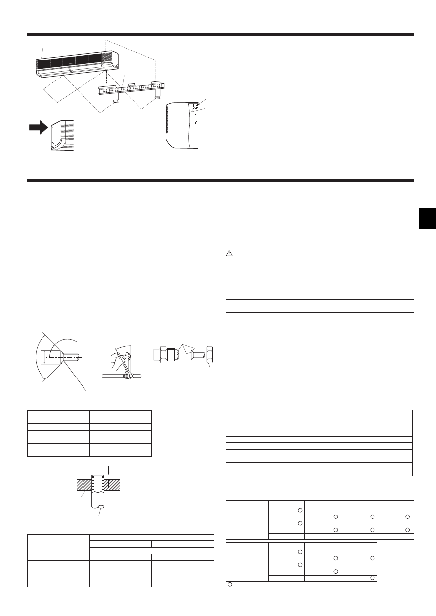
3.1. Check the indoor unit accessories (Fig. 3-1)
The indoor unit should be supplied with the following accessories.
PARTNUMBER
ACCESSORY
QUANTITY
LOCATION OF SETTING
1
Wall-fixing bracket
1
Fix at the back of the unit
2
Tapping screw 4 × 35
12
3
Insulation material
2
4
Band
4 (large) + 3 (small)
5
Felt tape
3
6
Drain socket
1
7
Wireless remote controller
1
8
Remote controller holder
1
9
Alkali batteries
2
RP50
2 (ø9.52, ø15.88)
RP100
1 (ø19.05)
0
Flare nut
RP60, 71
0
P60-100
Fig. 2-1
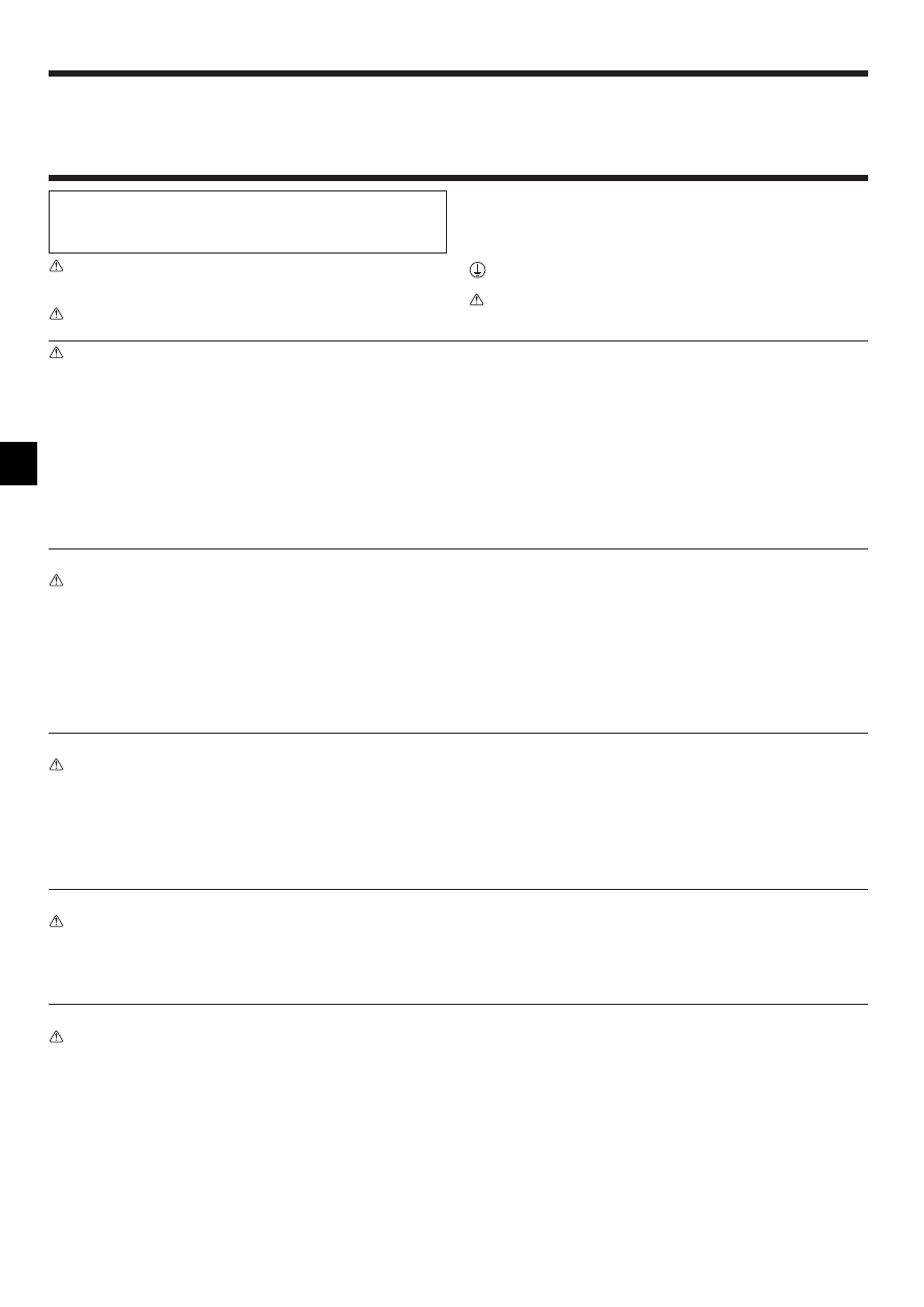
2.1. Outline dimensions (Indoor unit) (Fig. 2-1)
Select a proper position allowing the following clearances for installation and mainte-
nance.
(mm)
Models
W
D
H
A
B
C
E
F
50, 60, 71
1400
235
340
Min. 150
Min. 50
Min. 30
Min. 250 Min. 150
100
1680
235
340
Min. 150
Min. 50
Min. 30
Min. 250 Min. 150
Warning:
Mount the indoor unit on a ceiling strong enough to withstand the weight of the
unit.
2.2. Outline dimensions (Outdoor unit)
Refer to the outdoor unit installation manual.
D
A
C
F
E
H
W
B
Set inside the unit
990
245
285
455
10×91=(910)
19
10
184
280
60
30
30
30
29
80
900
91
90
610
314
280
180
240
225
18
18
A
B
C
G
I
H
F
E
D
1270
18 18
900
19
91
295
225
240
180
280
314
90
750
60
280
80
29
30
30
30
10
184
13×91=(1183)
245
285
595
I
H
H
E
D
B
G
A
C
F
1 50, 60, 71
(mm)
1
2
3
4
5
6
7
8
9
A
C
D
E
B
2 100
Fig. 3-1
Fig. 3-2
Fig. 3-3
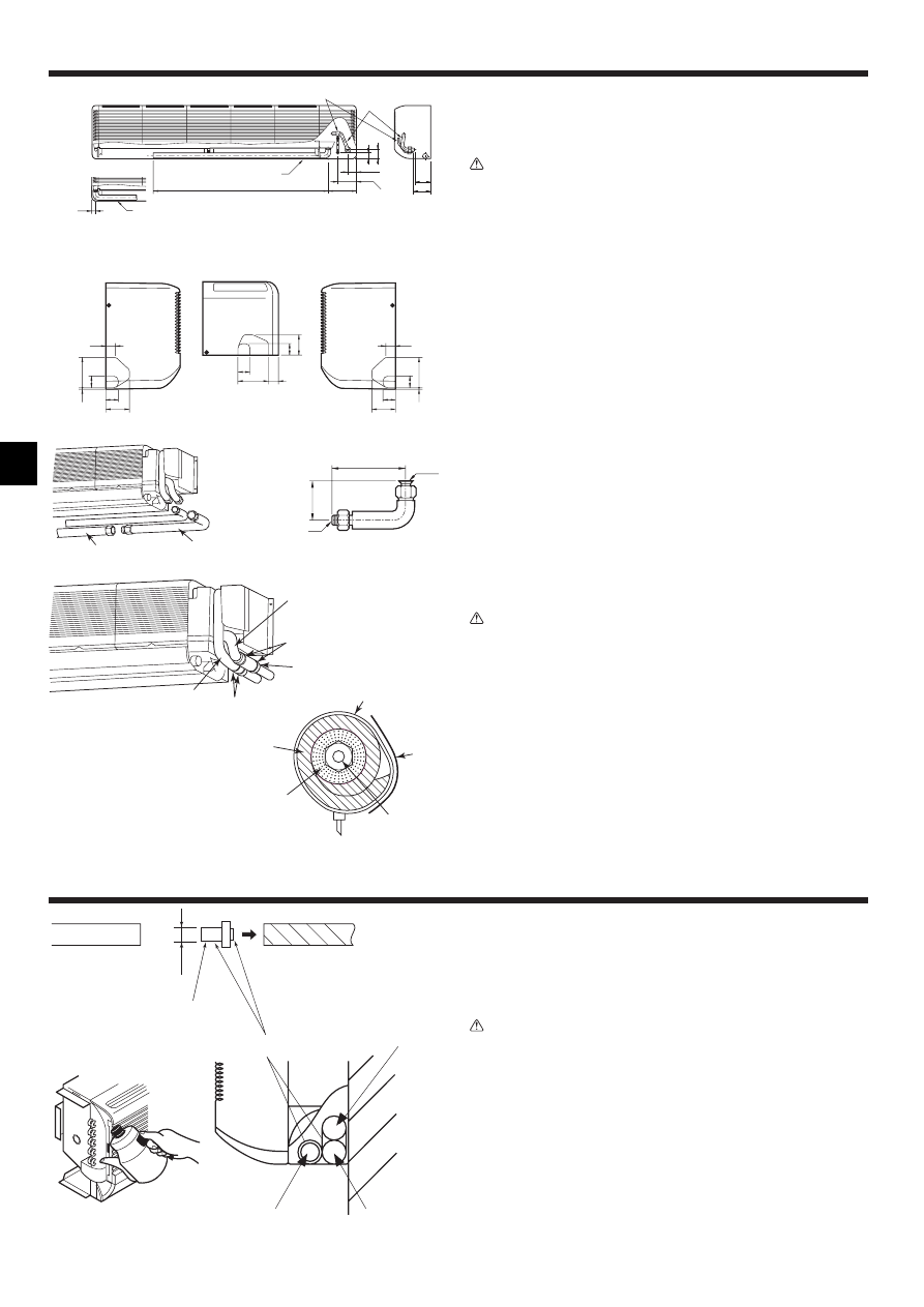
3.2. Installing the wall mounting fixture (Fig. 3-2)
1) Setting the wall mounting fixture and piping positions
s Using the wall mounting fixture, determine the unit’s installation position
and the locations of the piping holes to be drilled.
Warning:
Before drilling a hole in the wall, you must consult the building contractor.
A Indoor unit center line
B Left drain range
C Right drain range
D Hole for tapping screw
E Bolt hole
F Hole for tapping screw
G Contour of the unit
H Knockout hole for left rear piping
I Rear piping access hole (90-100 mm dia.)
2) Drilling the piping hole (Fig. 3-3)
s Use a core drill to make a hole of 90-100 mm diameter in the wall in the
piping direction, at the position shown in the diagram to the left.
s The hole should incline so that the outside opening is lower than the inside
opening.
s Insert a sleeve (with a 90 mm diameter and purchased locally) through the
hole.
Note:
The purpose of the hole’s inclination is to promote drain flow.
A Sleeve
B Hole
C (Indoors)
D Wall
E (Outdoors)
0
4
3. Installing the indoor unit
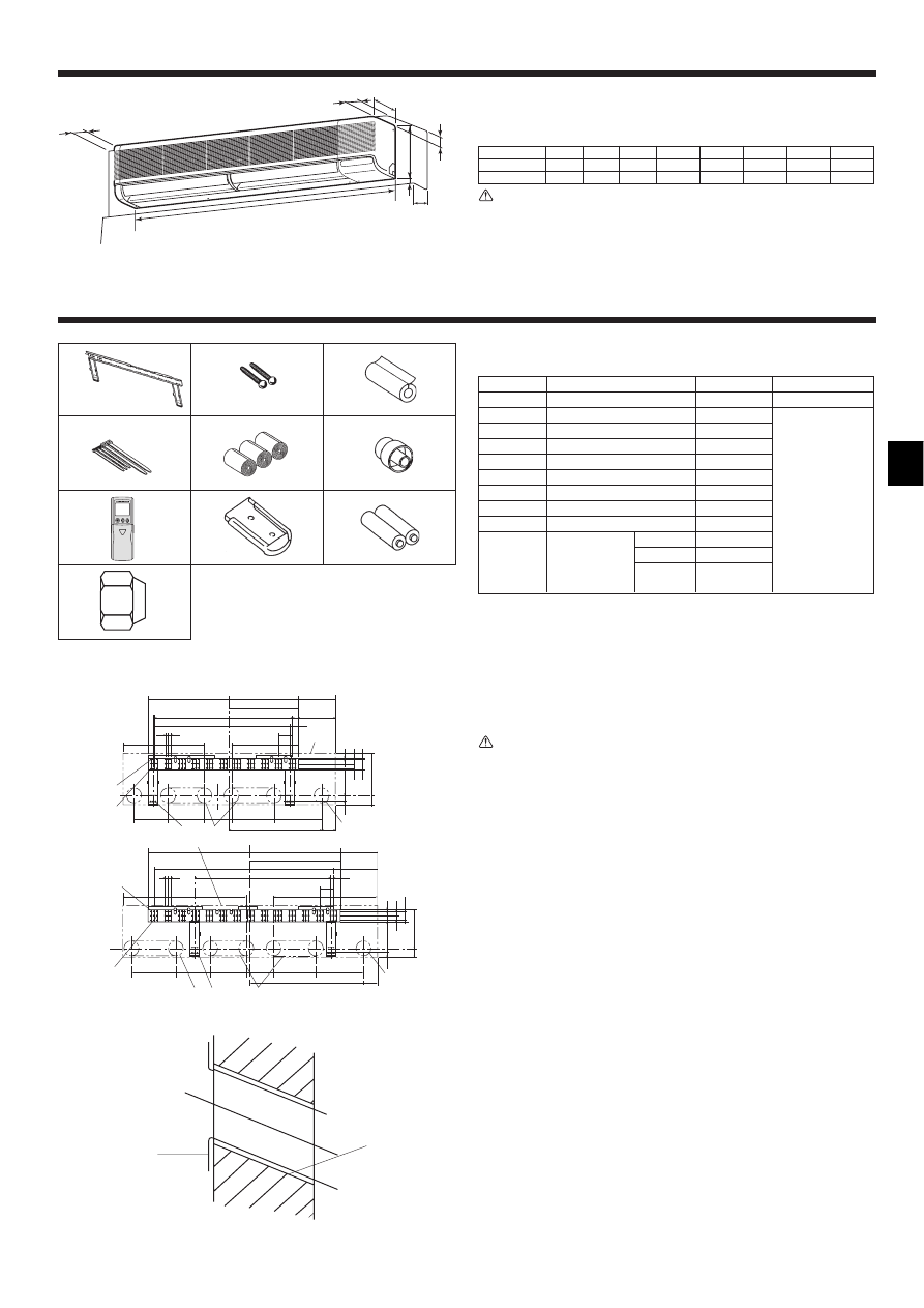
3) Installing the wall mounting fixture
s Since the indoor unit weighs near 30 kg, selection of the mounting location
requires thorough consideration. If the wall does not seem to be strong
enough, reinforce it with boards or beams before installation.
s The mounting fixture must be secured at both ends and at the centre, if
possible. Never fix it at a single spot or in any nonsymetrical way.
(If possible, secure the fixture at all the positions marked with a bold arrow.)
(Fig. 3-4)
s Secure the wall mounting fixture through its middle row of 12-mm-dia. holes
using locally purchased bolts (through bolts, bolt anchor and nut anchor) of
M10 or W3/8 threading. The bolt tip must not protrude by more than
15 mm from the wall surface. (Fig. 3-5)
Use at least two bolts for a concrete wall, and at least four bolts for a foamed
concrete wall.
A Wall-fixing bracket
B Mounting bolt
C Wall
Warning:
If possible, secure the fixture at all the positions marked with a bold arrow.
Caution:
The unit body must be mounted horizontally.
3.3. Preparation for piping connection
Remove the vinyl band that holds the drain piping.
• This vinyl band can be used to temporarily attach the pipes to the wall mounting
fixture while connecting the left pipe.
1) Rear, right and lower piping (Fig. 3-6)
1 Remove the right side panel.
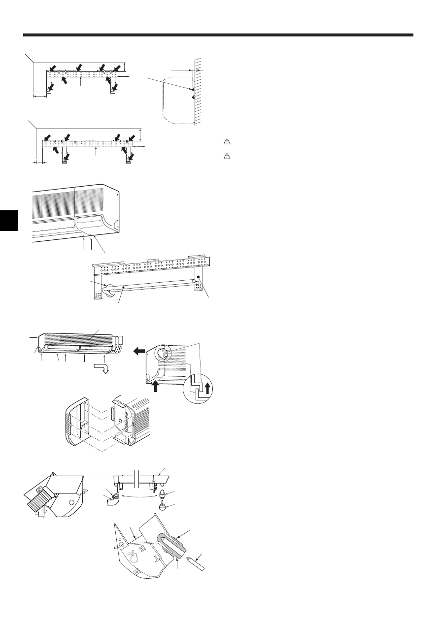
2) Left and left rear piping
1 Remove the side panel.
When embedding pipes into the wall (Fig. 3-7)
When the refrigerant pipe, drain pipes, internal/external connection lines, etc., are to
be embedded into the wall in advance, the extruding pipes, etc., may have to be bent
and have their length modified to the unit.
• Make the pipes to be embedded slightly longer than necessary, and install.
A Right side panel
C On-site piping
B Through hole
D Wall-fixing bracket 1
2 Remove the five screws indicated by the arrows in the diagram. (Fig. 3-8)
3 Remove the left side panel, then the lower panel.
1. While pushing up the front lower portion of the side panel (to disengage the side
panel catch from the unit catch), slide the upper portion of the side panel to the
left.
• When the indoor unit is already mounted, be sure the unit does not fall from the wall
mounting fixture.
• For reassembly, put the catch at the front lower portion of the side panel over the
unit body and push it to the right.
A Grille
D Catch
B Left side panel
E Side panel
C Lower panel
F Unit body
∗
Structure of the side panel and the unit body (Fig. 3-9)
1. Panel catch engages the unit body catch.
2. Panel catch is put in the unit body hole.
3. Panel catch engages the unit body catch.
4. Sheet metal of the unit body enters the panel.
5. Panel catch enters the unit body hole.
4 The drain hose can be connected at two different positions. Use the most conven-
ient position and, if necessary, exchange the position of the drain pan, rubber plug
and the drain hose. (Fig. 3-10)
G Drain pan
H Band
I Plug
J Drain hose
K Screwdriver
D
D
B
C
D
1
2
3
B
C
A
5
4
3
2
1
E
F
∗
4
G
I
K
J
H
K
I
G
H
Fig. 3-7
Fig. 3-9
Fig. 3-10
Fig. 3-4
Fig. 3-5
Fig. 3-6
Fig. 3-8
Min.165
Min.60
Min.500
A
Min.165
Min.60
Min.500
A
Max.15
C
B
1 60, 71
2 100
A
5
3. Installing the indoor unit
4. Installing the refrigerant piping
3.4. Mounting the indoor unit (Fig. 3-11)
1 Make sure to hang the metal catches of the indoor unit over the hooks of the wall
mounting fixture.
2 When the piping has been completed, use the securing screws to fix the indoor
unit on the wall mounting fixture.
Note:
Check that the catches of the indoor unit securely fit over the hooks of the wall
mounting fixture.
3 The screw indicated by the bold arrow is used only during transportation and
should be removed. Remove the screw before installation if there is not enough
space at the left side to remove it once the unit has been installed.
A Indoor unit
B Wall fixing bracket 1
C Hook
D Metal catch of the indoor unit
E Securing screws
1
3
2
D
C
Fig. 3-11
A
E
B
4.1. Precautions
4.1.1.
For devices that use R407C refrigerant
• Do not use the existing refrigerant piping.
• Do not use crushed, misshapen, or discolored tubing. The inside of the tub-
ing should be clean and free from harmful sulfuric compounds, oxidants,
dirt, debris, oils and moisture.
• Store the piping to be used during installation indoors and keep both ends of
the piping sealed until just before brazing.
• Use ester oil, ether oil or alkylbenzene (small amount) as the refrigerator oil
to coat flares and flange connections.
• Use liquid refrigerant to fill the system.
• Do not use a refrigerant other than R407C.
• Use a vacuum pump with a reverse flow check valve.
• Do not use the tools that are used with conventional refrigerants.
• Do not use a charging cylinder.
• Be especially careful when managing the tools.
• Do not use commercially available dryers.
4.1.2.
For devices that use R410A refrigerant
• Use ester oil, ether oil, alkylbenzene oil (small amount) as the refrigeration
oil applied to the flared sections.
• Use C1220 copper phosphorus, for copper and copper alloy seamless pipes,
to connect the refrigerant pipes. Use refrigerant pipes with the thicknesses
specified in the table to the below. Make sure the insides of the pipes are
clean and do not contain any harmful contaminants such as sulfuric com-
pounds, oxidants, debris, or dust.
Warning:
When installing or moving the air conditioner, use only the specified refriger-
ant (R410A) to charge the refrigerant lines. Do not mix it with any other refriger-
ant and do not allow air to remain in the lines. Air enclosed in the lines can
cause pressure peaks resulting in a rupture and other hazards.
RP35, 50
RP60-140
Liquid pipe
ø6.35 thickness 0.8 mm
ø9.52 thickness 0.8 mm
Gas pipe
ø12.7 thickness 0.8 mm
ø15.88 thickness 1.0 mm
• Do not use pipes thinner than those specified above.
4.2. Connecting pipes (Fig. 4-1)
• When commercially available copper pipes are used, wrap liquid and gas pipes
with commercially available insulation materials (heat-resistant to 100 °C or more,
thickness of 12 mm or more).
• The indoor parts of the drain pipe should be wrapped with polyethylene foam insu-
lation materials (specific gravity of 0.03, thickness of 9 mm or more).
• Apply thin layer of refrigerant oil to pipe and joint seating surface before tightening
flare nut.
• Use two wrenches to tighten piping connections.
• Use refrigerant piping insulation provided to insulate indoor unit connections. Insu-
late carefully.
B Flare nut tightening torque
Copper pipe O.D.
Flare nut O.D.
Tightening torque
(mm)
(mm)
(N·m)
ø6.35
17
14 - 18
ø6.35
22
34 - 42
ø9.52
22
34 - 42
ø12.7
26
49 - 61
ø12.7
29
68 - 82
ø15.88
29
68 - 82
ø15.88
36
100 - 120
ø19.05
36
100 - 120
C Apply refrigerating machine oil over the entire flare seat surface.
D Use correct flare nuts meeting the pipe size of the outdoor unit.
Available pipe size
RP35, 50
RP60
RP71
RP100, 125, 140
Liquid side
ø6.35
ø6.35
–
–
ø9.52
ø9.52
ø9.52
ø9.52
ø12.7
–
–
–
Gas side
ø15.88
ø15.88
ø15.88
ø15.88
–
–
–
ø19.05
P25
P35, 50, 60, 71 P100, 125, 140
Liquid side
ø6.35
–
–
–
ø9.52
ø9.52
ø12.7
–
–
Gas side
–
ø15.88
–
–
–
ø19.05
: Factory flare nut attachment to the heat-exchanger.
A Flare cutting dimensions
Copper pipe O.D.
Flare dimensions
(mm)
øA dimensions (mm)
ø6.35
8.7 - 9.1
ø9.52
12.8 - 13.2
ø12.7
16.2 - 16.6
ø15.88
19.3 - 19.7
ø19.05
23.6 - 24.0
90
°
±0.5
°
ø
A
R0.4~R0.8
A
45°±2°
B
C
D
Fig. 4-1
A Die
B Copper pipe
A
A
B
Fig. 4-2
Copper pipe O.D.
A (mm)
(mm)
Flare tool for R-22·R407C
Flare tool for R410A
Clutch type
ø6.35 (1/4")
0 - 0.5
1.0 - 1.5
ø9.52 (3/8")
0 - 0.5
1.0 - 1.5
ø12.7 (1/2")
0 - 0.5
1.0 - 1.5
ø15.88 (5/8")
0 - 0.5
1.0 - 1.5
ø19.05 (3/4")
0 - 0.5
1.0 - 1.5
6
4.4. Refrigerant piping (Fig. 4-6)
1) Indoor unit
Caution:
Before connecting right, lower, left or left rear piping, connect the supplied L-
shaped connection pipe B to the on-site piping.
Liquid pipe
Gas pipe
Insulation material 3
Band (large) 4
Band (small) 4
Band (small) 4
Tape
Thermal insulating
material for
refrigerant piping
Thermal insulating
material for liquid pipe
Liquid pipe
ø
20
O.D
Drain socket
Apply PVC adhesive
On-site drain pipe
Unit’s drain pipe
Felt tape 5
Liquid pipe
Drain pipe
Gas pipe
5. Drainage piping work (Fig. 5-1)
• Drain pipes should have an inclination of 1/100 or more.
• Use PVC pipe VP-20 (O.D. ø26 PVC TUBE) for drain piping.
• Drain pipes can be cut with a knife at the connection point according to the on-site
conditions.
• When connecting the VP-20, use adhesive to attach the supplied drain socket.
• To prevent dripping condensation, put felt tape 5 over the insulation materials on
the refrigerant and drain pipes within the unit as shown in the diagram.
Caution:
The drain pipe should be installed according to this Installation Manual to en-
sure correct drainage. Thermal insulation of the drain pipes is necessary to
prevent condensation. If the drain pipes are not properly installed and insu-
lated, condensation may drip on the ceiling, floor or other possessions.
Fig. 5-1
Fig. 4-6
25
1110
183
120
55
42
58
111
C
D
A
D
C
B
B
B
E
1
Fig. 4-3
2
30
37
74
100
39
4
30
37
74
39
98
32
37
65
100
39
4
G
F
H
I
4.3. Positioning refrigerant and drain piping
1 Position of refrigerant and drain piping (Fig. 4-3)
2 Determine the position of the knockout holes on the unit body (Fig. 4-4)
• Make the knockout holes using a saw blade or an adequate knife.
Caution:
The side panel must be removed before drilling a knockout hole in it.
If a hole is made with the side panel in place, the refrigerant pipe within the unit
could be damaged.
3 L-shaped connection pipe (for gas piping) (Fig. 4-5)
A 107 mm (60,71), 102 mm (100)
H For lower-side piping
B Drain hose
I For right-side piping
C Liquid pipe
J L-shaped connection pipe (option)
D Gas pipe
K Unit side
E Drain hose in left-side piping
L On-site piping side
F Knockout holes on the unit body
M Piping
G For left-side piping
3
Fig. 4-4
Fig. 4-5
J
M
K
J
L
340
80
4. Installing the refrigerant piping
7
6. Electrical work
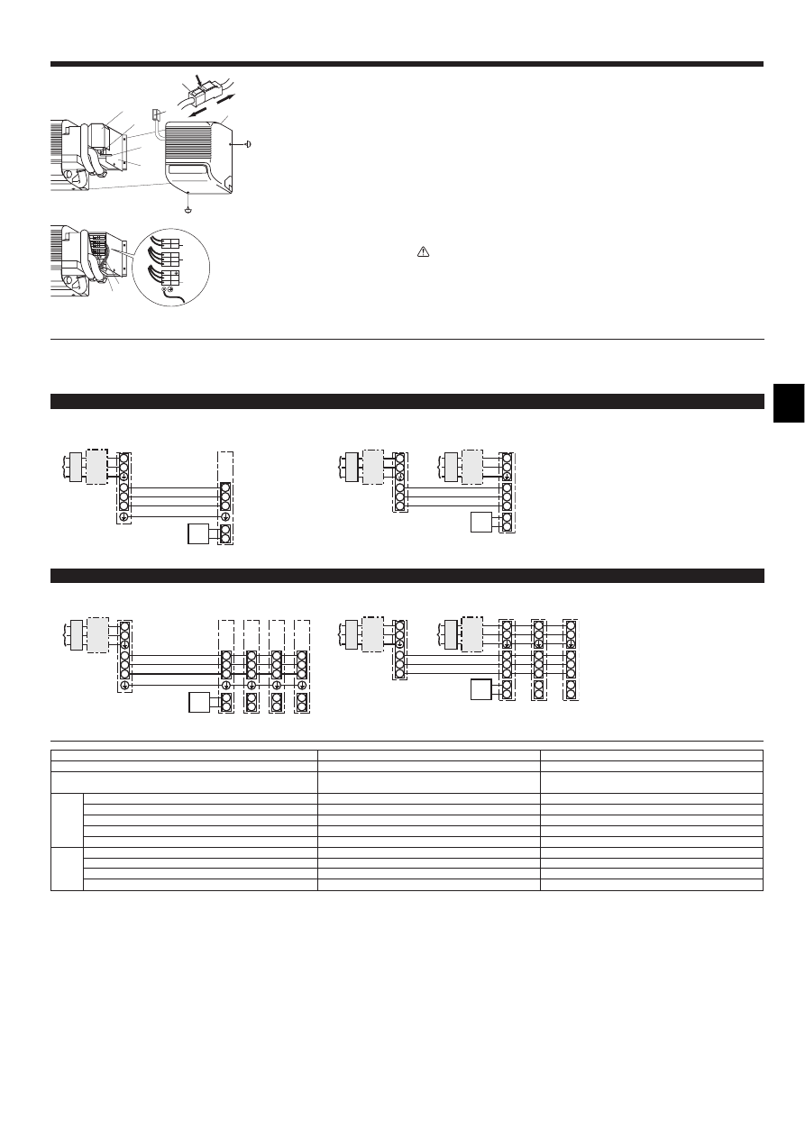
6.1. Indoor unit (Fig. 6-1)
1 Remove the right side panel.
To do this, remove the screws on the lower and right sides.
Remove the securing screw on the terminal board cover to take away the cover.
2 Connect the power, control line. (3 × 2.5 mm
2
2 poler).
s This cables shall not lighter than polychloroprene sheathed flexible cord.
(design 245 IEC 57)
s Fix power source wiring to control box using buffer bushing for tensile force.
(PG connection or the like.)
• Since the electric box may need to be pulled out for servicing or other occasions,
wires must have enough slack.
• Class 3 grounding work must be conducted (grounding wire size: 2.5 mm
2
or more).
After wiring is completed, reinstall the parts in the reverse order of removal.
Warning:
Wiring should be done so that the power lines are not subject to tension. Oth-
erwise, heat may be generated or fire may occur.
1
Fig. 6-1
I
J
G
H
1
S1
S2
S3
2
K
L
N
*1. A breaker with at least 3 mm contact separation in each pole shall be provided. Use non-fuse breaker (NF) or earth leakage breaker (NV).
*2. <For 25-140 outdoor unit application>
Max. 45 m
If 2.5 mm
2
used, Max. 50 m
If 2.5 mm
2
used and S3 separated, Max. 80 m
For PUHZ-RP100/125/140 YHA application, use shield wires. The shield part must be grounded with the indoor unit OR the outdoor unit, NOT with both.
<For 200/250 outdoor unit application>
Max. 18 m
If 2.5 mm
2
used, Max. 30 m
If 4 mm
2
used and S3 separated, Max. 50 m
If 6 mm
2
used and S3 separated, Max. 80 m
*3. The 10 m wire is attached in the remote controller accessory. Max. 500 m
*4. The figures are NOT always against the ground.
S3 terminal has DC 24 V against S2 terminal. However between S3 and S1, these terminals are not electrically insulataed by the transformer or other device.
Notes: 1. Wiring size must comply with the applicable local and national code.
2. Power supply cords and indoor unit/outdoor unit connecting cords shall not be lighter than polychloroprene sheathed flexible cord. (Design 245 IEC 57)
3. Install an earth longer than other cables.
Indoor unit model
Indoor unit power supply (Heater)
Indoor unit input capacity (Heater)
*1
Main switch (Breaker)
Indoor unit power supply (Heater)
Indoor unit power supply (Heater) earth
Indoor unit-Outdoor unit
*2
Indoor unit-Outdoor unit earth
*2
Remote controller-Indoor unit
*3
Indoor unit (Heater) L-N
*4
Indoor unit-Outdoor unit S1-S2
*4
Indoor unit-Outdoor unit S2-S3
*4
Remote controller-Indoor unit
*4
PKA
PKH
–
~/N (single), 50 Hz, 230 V
–
16 A
–
2 × Min. 1.5
–
1 × Min. 1.5
3 × 1.5 (polar)
3 × 1.5 (polar)
1 × Min. 1.5
–
–
–
–
AC 230 V
AC 230 V
AC 230 V
DC 24 V
DC 24 V
–
–
C
ir
c
u
it
ra
ti
n
g
W
ir
in
g
Wire
No.
×
si
ze
(mm
2
)
6.1.1.
Indoor unit power supplied from outdoor unit
The following connection patterns are available.
The outdoor unit power supply patterns vary on models.
1:1 System
S1
S2
L
N
1
2
S1
S2
S3
S3
A
B
C
D
E
F
G
S1
S2
L
N
1
2
S1
S2
S3
1
2
S1
S2
S3
S3
1
2
S1
S2
S3
1
2
S1
S2
S3
A
B
C
D
E
F
G
G
G
G
<For models with heater>
S1
S2
L
N
1
2
L
N
S1
S2
S3
S3
A
B
C
D
G
H
E
F
B
C
S1
S2
L
N
1
2
L
N
S1
S2
S3
1
2
L
N
S1
S2
S3
1
2
L
N
S1
S2
S3
S3
A
B
C
D
E
C
G
G
G
B
H
F
Simultaneous twin/triple/four system
<For models without heater>
<For models with heater>
* Affix a label A that is included with the manuals near each wiring diagram for the indoor and outdoor units.
A Outdoor unit power supply
B Earth leakage breaker
C Wiring circuit breaker or isolating switch
D Outdoor unit
E Indoor unit/outdoor unit connecting cords
F Remote controller
G Indoor unit
H Heater power supply
<For models without heater>
2
A Terminal board cover
B Screw
C Band
D Printed circuit board cover
E Right side panel
F Coupler connector
G Terminal board for remote con-
troller (option)
H Terminal board for control lines
from the outdoor unit
I Power supply wiring & connec-
tion wiring
J Cord clamp
K Terminal board for electric heater
power (PKH models only)
A
B
C
D
E
F
F
8
*1. A breaker with at least 3 mm contact separation in each pole shall be provided. Use non-fuse breaker (NF) or earth leakage breaker (NV).
*2. Max. 120 m
For PUHZ-RP100/125/140 YHA application, use shield wires. The shield part must be grounded with the indoor unit OR the outdoor unit, NOT with both.
*3. The 10 m wire is attached in the remote controller accessory. Max. 500 m
*4. The figures are NOT always against the ground.
Notes: 1. Wiring size must comply with the applicable local and national code.
2. Power supply cords and indoor unit/outdoor unit connecting cords shall not be lighter than polychloroprene sheathed flexible cord. (Design 245 IEC 57)
3. Install an earth longer than other cables.
Indoor unit model
Indoor unit power supply
Indoor unit input capacity
*1
Main switch (Breaker)
Indoor unit power supply
Indoor unit power supply earth
Indoor unit-Outdoor unit
*2
Indoor unit-Outdoor unit earth
Remote controller-Indoor unit
*3
Indoor unit L-N
*4
Indoor unit-Outdoor unit S1-S2
*4
Indoor unit-Outdoor unit S2-S3
*4
Remote controller-Indoor unit
*4
PKA
~/N (single), 50 Hz, 230 V
16 A
2 × Min. 1.5
1 × Min. 1.5
2 × Min. 0.3
–
–
AC 230 V
–
DC 24 V
DC 12 V
C
ir
c
u
it
ra
ti
n
g
W
ir
in
g
Wire
No.
×
si
ze
(mm
2
)
6. Electrical work
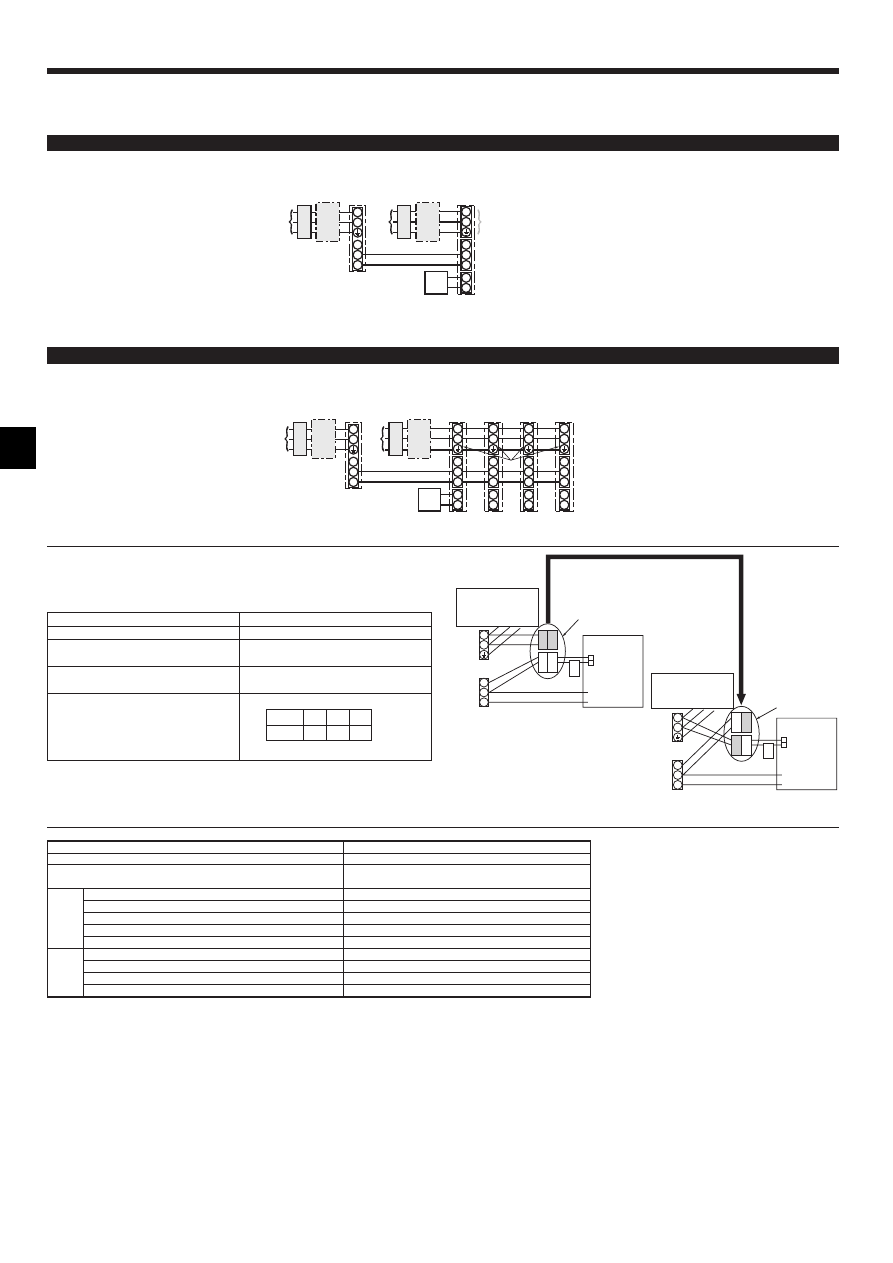
6.1.2.
Separate indoor unit/outdoor unit power supplies (For PUHZ application only)
The following connection patterns are available.
The outdoor unit power supply patterns vary on models.
1:1 System
<For models without heater>
* The optional wiring replacement kit is required.
S1
S2
L
N
1
2
L
N
S1
S2
S3
S3
A
C
B
D
J
E
B
C
F
G
H
S1
S2
L
N
1
2
L
N
S1
S2
S3
1
2
L
N
S1
S2
S3
1
2
L
N
S1
S2
S3
1
2
L
N
S1
S2
S3
S3
A
B
C
D
E
J
B
C
F
H
G
G
G
G
* Affix a label B that is included with the manuals near each wiring diagram for the indoor and outdoor units.
A Outdoor unit power supply
B Earth leakage breaker
C Wiring circuit breaker or isolating switch
D Outdoor unit
E Indoor unit/outdoor unit connecting cords
F Remote controller
G Indoor unit
H Option
J Indoor unit power supply
<For models without heater>
* The optional wiring replacement kits are required.
Simultaneous twin/triple/four system
If the indoor and outdoor units have separate power supplies, refer to the table at the
below. If the optional wiring replacement kit is used, change the indoor unit electrical
box wiring refering to the figure in the right and the DIP switch settings of the outdoor
unit control board.
* Affix a label B that is included with the manuals near each wiring diagram for the indoor and outdoor units.
A Outdoor unit power supply
B Earth leakage breaker
C Wiring circuit breaker or isolating switch
D Outdoor unit
E Indoor unit/outdoor unit connecting cords
F Remote controller
G Indoor unit
H Option
J Indoor unit power supply
ON
OFF
1
2
(SW8)
3
Indoor power supply terminal kit (option)
Indoor unit electrical box connector con-
nection change
Label affixed near each wiring diagram
for the indoor and outdoor units
Outdoor unit DIP switch settings (when
using separate indoor unit/outdoor unit
power supplies only)
Indoor unit specifications
Required
Required
Required
Electric heater
(For models with
heater)
Connectors (connections when shipped
from the factory are for indoor unit power
supplied from outdoor unit)
Indoor unit power supplied from outdoor unit
(when shipped from factory)
If the indoor and
outdoor units have
separate power
supplies, change the
connections of the
connectors as shown
in the following
figure.
Connectors
Indoor unit
control board
Separate indoor unit/outdoor unit power
supplies
Electric heater
(For models with
heater)
S1
S2
S3
L
N
BLUE
BLUE
YELLOW
YELLOW
CND
CND
ORANGE
CND
ORANGE
S1
S2
S3
L
N
YELLOW
BLUE
BLUE
YELLOW
CND
Indoor unit
control board
* There are three types of labels (labels A, B, and C). Affix the appropriate labels to
the units according to the wiring method.
9
ON
OFF
STAND
BY
COOL
HEAT
D
B
1
C
A
2
6. Electrical work
6.2. Remote controller
6.2.1.
For wired remote controller
1) Installing procedures
(1) Select an installing position for the remote controller. (Fig. 6-2)
The temperature sensors are located on both remote controller and indoor unit.
s Procure the following parts locally:
Two piece switch box
Thin copper conduit tube
Lock nuts and bushings
A Remote controller profile
B Required clearances surrounding the remote controller
C Installation pitch
(2) Seal the service entrance for the remote controller cord with putty to prevent pos-
sible invasion of dew drops, water, cockroaches or worms. (Fig. 6-3)
A For installation in the switch box:
B For direct installation on the wall select one of the following:
• Prepare a hole through the wall to pass the remote controller cord (in order to run
the remote controller cord from the back), then seal the hole with putty.
• Run the remote controller cord through the cut-out upper case, then seal the cut-
out notch with putty similarly as above.
B-1. To lead the remote controller cord from the back of the controller:
B-2. To run the remote controller cord through the upper portion:
(3) For direct installation on the wall
C Wall
D Conduit
E Lock nut
F Bushing
G Switch box
H Remote controller cord
I Seal with putty
J Wood screw
2) Connecting procedures (Fig. 6-4)
1 Connect the remote controller cord to the terminal block.
A To TB5 on the indoor unit
B TB6 (No polarity)
3) Two remote controllers setting
If two remote controllers are connected, set one to “Main” and the other to “Sub”. For
setting procedures, refer to “Function selection of remote controller” in the operation
manual for the indoor unit.
6.2.2.
For wireless remote controller
1) Installation area
• Area in which the remote controller is not exposed to direct sunshine.
• Area in which there is no nearby heating source.
• Area in which the remote controller is not exposed to cold (or hot) winds.
• Area in which the remote controller can be operated easily.
• Area in which the remote controller is beyond the reach of children.
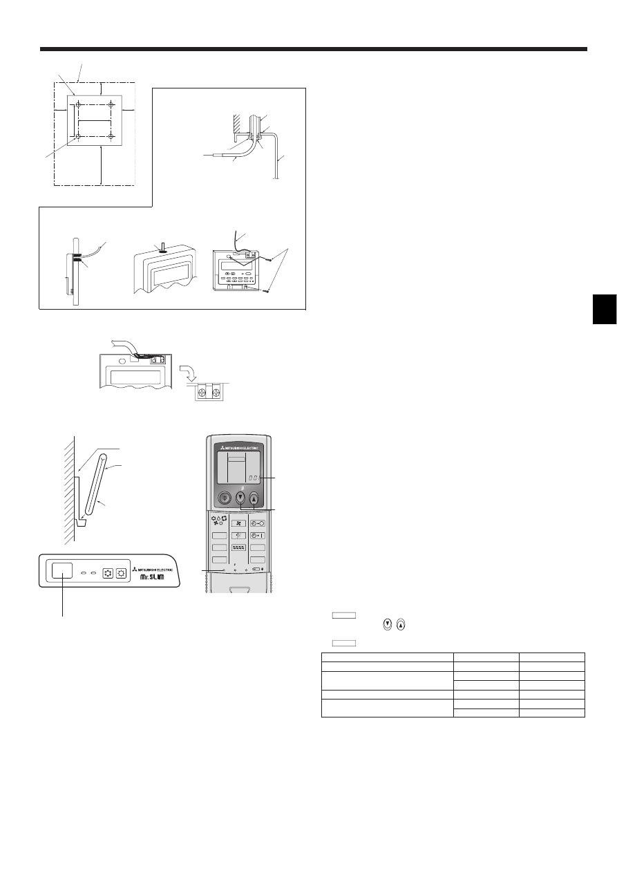
2) Installation method (Fig. 6-5)
1 Attach the remote controller holder to the desired location using two tapping screws.
2 Place the lower end of the controller into the holder.
A Remote controller
B Wall
C Display panel
D Receiver
• The signal can travel up to approximately 7 meters (in a straight line) within 45
degrees to both right and left of the center line of the receiver.
3) Setting (Fig. 6-6)
1 Insert batteries.
2 Press the SET button with something sharp at the end.
MODEL SELECT
blinks and Model No. is lighted.
3 Press the temp
button to set the Model No.
4 Press the SET button with something sharp at the end.
MODEL SELECT
and Model No. are lighted for three seconds, then turned off.
30
46
30
30
120
83.5
A
B
C
F
A
H
C
D
E
G
I
I
I
H
B
B-1.
B-2.
Fig. 6-3
A
AB
TB6
B
Indoor
Outdoor
A Model No.
PLH, PCH, PKH (35, 50)
PUH
001
PLA, PCA, PKA-G (35, 50)
PUH, PUHZ, SUZ
001
PU
033
PKH (60, 71, 100)
PUH
003
PKA-F (50, 60, 71, 100)
PUH, PUHZ, SUZ
003
PU
035
ON/OFF
TEMP
FAN
VANE
TEST RUN
AUTO STOP
AUTO START
h
min
LOUVER
MODE
CHECK
RESET
SET
CLOCK
MODEL SELECT
2,4
3
A
Fig. 6-5
Fig. 6-6
Fig. 6-2
J
H
Fig. 6-4
10
A Pair No. of wireless remote controller
Indoor PC board
0
Factory setting
1
Cut J41
2
Cut J42
3–9
Cut J41, J42
4) Assigning a remote controller to each unit (Fig. 6-7)
Each unit can be operated only by the assigned remote controller.
Make sure each pair of an indoor unit PC board and a remote controller is assigned
to the same pair No.
5) Wireless remote controller pair number setting operation
1 Press the SET button with something sharp at the end.
Start this operation from the status of remote controller display turned off.
MODEL SELECT
blinks and Model No. is lighted.
2 Press the
min
button twice continuously.
Pair No. “0” blinks.
3 Press the temp
button to set the pair number you want to set.
4 Press the SET button with something sharp at the end.
Set pair number is lighted for three seconds then turned off.
Fig. 6-7
Fig. 6-8
3
CHECK
4
CHECK
ON/OFF
TEMP
FAN
VANE
TEST RUN
AUTO STOP
AUTO START
h
min
LOUVER
MODE
CHECK
RESET
SET
CLOCK
CHECK
E
C,D
F
A
B
Fig. 6-9
2
CHECK
CHECK
1
6. Electrical work
⁄ Mode number
⁄ Setting number
⁄ Refrigerant address
⁄ Unit number
1
2
3
4
ON/OFF
TEMP
FAN
VANE
TEST RUN
AUTO STOP
AUTO START
h
min
LOUVER
MODE
CHECK
RESET
SET
CLOCK
MODEL SELECT
1,4
3
A
2
PAR-21MAA
ON/OFF
FILTER
CHECK
OPERATION
CLEAR
TEST
TEMP.
MENU
BACK
DAY
MONITOR/SET
CLOCK
ON/OFF
A
B
D
C
G
E
F
4
1
2
1
3 4
1
2
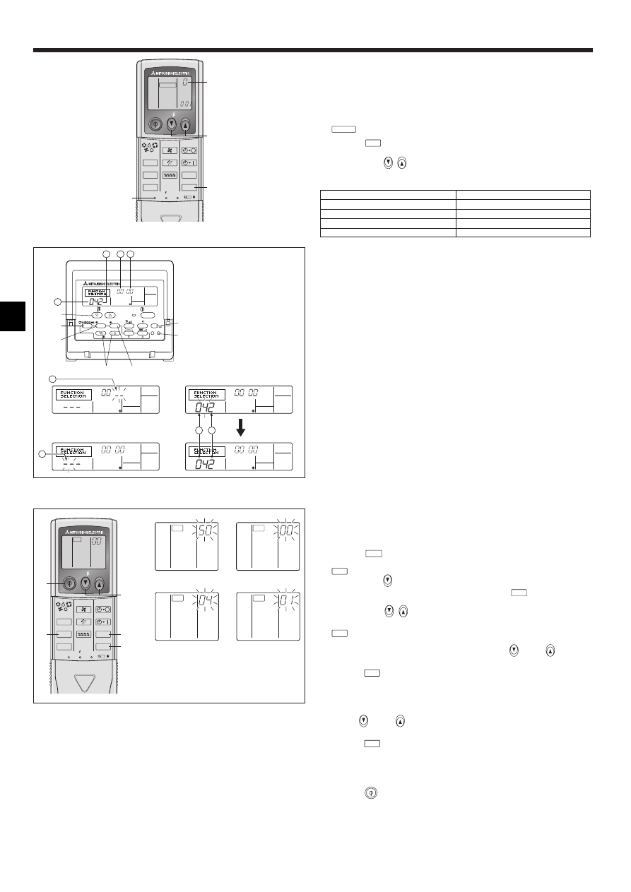
6.3. Function settings
6.3.1
Function setting on the unit (Selecting the unit functions)
1) For wired remote controller (Fig. 6-8)
Changing the power voltage setting
• Be sure to change the power voltage setting depending on the voltage used.
1 Go to the function setting mode.
Switch OFF the remote controller.
Press the A and B buttons simultaneously and hold them for at least 2
seconds. FUNCTION will start to flash.
2 Use the C button to set the refrigerant address (3) to 00.
3 Press D and [--] will start to flash in the unit number (4) display.
4 Use the C button to set the unit number (4) to 00.
5 Press the E MODE button to designate the refrigerant address/unit number. [--]
will flash in the mode number (
1) display momentarily.
6 Press the F buttons to set the mode number (1) to 04.
7 Press the G button and the current set setting number (2) will flash.
Use the F button to switch the setting number in response to the power supply
voltage to be used.
Power supply voltage
240 V
: setting number = 1
220 V, 230 V : setting number = 2
8 Press the MODE button E and mode and the setting number (1) and (2) will
change to being on constantly and the contents of the setting can be confirmed.
9 Press the FILTER A and TEST RUN B buttons simultaneously for at least two
seconds. The function selection screen will disappear momentarily and the air
conditioner OFF display will appear.
2) For wireless remote controller (Fig. 6-9)
Changing the power voltage setting
• Be sure to change the power voltage setting depending on the voltage used.
1 Go to the function select mode
Press the
CHECK
button F twice continuously.
(Start this operation from the status of remote controller display turned off.)
CHECK
is lighted and “00” blinks.
Press the temp
button C once to set “50”. Direct the wireless remote control-
ler toward the receiver of the indoor unit and press the
h
button A.
2 Setting the unit number
Press the temp
button C and D to set the unit number “00”. Direct the
wireless remote controller toward the receiver of the indoor unit and press the
min
button B.
3 Selecting a mode
Enter 04 to change the power voltage setting using the
C and
D buttons.
Direct the wireless remote controller toward the receiver of the indoor unit and
press the
h
button A.
Current setting number:
1 = 1 beep (one second)
2 = 2 beeps (one second each)
3 = 3 beeps (one second each)
4 Selecting the setting number
Use the
C and
D buttons to change the power voltage setting to 01 (240
V). Direct the wireless remote controller toward the sensor of the indoor unit and
press the
h
button A.
5 To select multiple functions continuously
Repeat steps 3 and 4 to change multiple function settings continuously.
6 Complete function selection
Direct the wireless remote controller toward the sensor of the indoor unit and
press the
button E.
Note:
Whenever changes are made to the function settings after installation or main-
tenance, be sure to record the changes with a mark in the “Setting” column of
the Function table.
6.3.2
Function setting on the remote controller
Refer to the indoor unit operation manual.
11
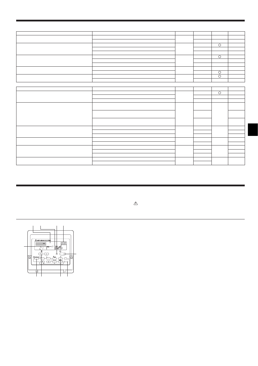
6. Electrical work
Function table
Select unit number 00
Mode
Power failure automatic recovery
Indoor temperature detecting
LOSSNAY connectivity
Power voltage
Auto mode (only for PUHZ)
Settings
Not available
Available
*1
Indoor unit operating average
Set by indoor unit’s remote controller
Remote controller’s internal sensor
Not Supported
Supported (indoor unit is not equipped with outdoor-air intake)
Supported (indoor unit is equipped with outdoor-air intake)
240 V
220 V, 230 V
Energy saving cycle automatically enabled
Energy saving cycle automatically disabled
Mode no.
Setting no. Initial setting
setting
01
1
*2
2
*2
1
02
2
3
–
1
03
2
3
–
04
1
2
05
1
2
Mode
Filter sign
Fan speed
No. of air outlets
Installed options (high-performance filter)
Up/down vane setting
Energy saving air flow
(Heating mode)
Settings
100Hr
2500Hr
No filter sign indicator
Standard (PLH/PLA-P·AA(H)/PLA-RP·AA)/Silent (PLH/PLA-
P·KA(H), PCH/PCA)
High ceiling 1 (PLH/PLA-P·AA(H)/PLA-RP·AA)/Standard (PLH/
PLA-P·KA(H), PCH/PCA)
High ceiling 2 (PLH/PLA-P·AA(H)/PLA-RP·AA)/High ceiling
(PLH/PLA-P·KA(H), PCH/PCA)
4 directions
3 directions
2 directions
Not supported
Supported
No vanes
Equipped with vanes (vanes angle setup 1)
Equipped with vanes (vanes angle setup 2)
Disabled
Enabled
Mode no.
Setting no. Initial setting
setting
1
07
2
3
1
08
2
–
3
1
09
2
–
3
10
1
2
–
11
1
2
–
3
12
1
2
–
Select unit numbers 01 to 03 or all units (AL [wired remote controller]/07 [wireless remote controller])
7. Test run
7.1. Before test run
s After completing installation and the wiring and piping of the indoor and
outdoor units, check for refrigerant leakage, looseness in the power supply
or control wiring, wrong polarity, and no disconnection of one phase in the
supply.
s Use a 500-volt megohmmeter to check that the resistance between the power
supply terminals and ground is at least 1.0 MΩ
Ω
Ω
Ω
Ω
.
s Do not carry out this test on the control wiring (low voltage circuit) termi-
nals.
Warning:
Do not use the air conditioner if the insulation resistance is less than 1.0 MΩ
Ω
Ω
Ω
Ω
.
Insulation resistance
7.2. Test run
The following 3 methods are available.
7.2.1.
Using wired remote controller (Fig. 7-1)
1 Turn on the power at least 12 hours before the test run.
2 Press the [TEST] button twice. ➡ “TEST RUN” liquid crystal display
3 Press the [Mode selection] button. ➡ Make sure that wind is blown out.
4 Press the [Mode selection] button and switch to the cooling (or heating) mode.
➡ Make sure that cold (or warm) wind is blown out.
5 Press the [Fan speed] button. ➡ Make sure that the wind speed is switched.
6 Check operation of the outdoor unit fan.
7 Release test run by pressing the [ON/OFF] button. ➡ Stop
8 Register a telephone number.
The telephone number of the repair shop, sales office, etc., to contact if an error
occurs can be registered in the remote controller. The telephone number will be
displayed when an error occurs. For registration procedures, refer to the opera-
tion manual for the indoor unit.
Fig. 7-1
˚C
˚C
SIMPLE
PAR-21MAA
ON/OFF
FILTER
CHECK
OPERATION
CLEAR
TEST
TEMP.
MENU
BACK
DAY
MONITOR/SET
CLOCK
ON/OFF
TEST RUN
COOL, HEAT
A
F
C
E
D B
M
I
H G
A ON/OFF button
B Test run display
C Indoor temperature liquid line
temperature display
D ON/OFF lamp
E Power display
F Error code display
Test run remaining time dis-
play
G Set temperature button
H Mode selection button
I Fan speed button
M TEST button
*1 When the power supply returns, the air conditioner will start 3 minutes later.
*2 Power failure automatic recovery initial setting depends on the connecting outdoor unit.
12
ON/OFF
TEMP
FAN
VANE
TEST RUN
AUTO STOP
AUTO START
h
min
LOUVER
MODE
CHECK
RESET
SET
CLOCK
TEST RUN
5
7
A
3,4
2
6
Fig. 7-2
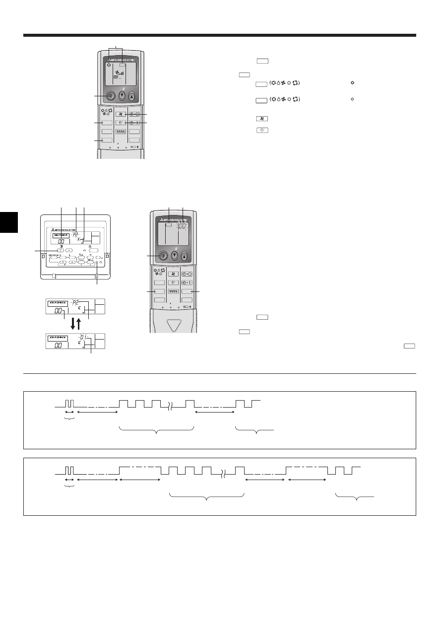
7.2.2.
Using wireless remote controller (Fig. 7-2)
1 Turn on the power to the unit at least 12 hours before the test run.
2 Press the
TEST RUN
button twice continuously.
(Start this operation from the status of remote controller display turned off.)
A TEST RUN and current operation mode are displayed.
3 Press the
MODE
button to activate
COOL
mode, then check whether
cool air is blown out from the unit.
4 Press the
MODE
button to activate
HEAT
mode, then check whether
warm air is blown out from the unit.
5 Press the
FAN
button and check whether fan speed changes.
6 Press the
VANE
button and check whether the auto vane operates properly.
7 Press the ON/OFF button to stop the test run.
Note:
• Point the remote controller towards the indoor unit receiver while following
steps 2 to 7.
• It is not possible to run the in FAN, DRY or AUTO mode.
7.2.3.
Using SW4 in outdoor unit
Refer to the outdoor unit installation manual.
7.3. Self-check
7.3.1.
Wired remote controller (Fig. 7-3)
1 Turn on the power.
2 Press the [CHECK] button twice.
3 Set refrigerant address with [TEMP] button if system control is used.
4 Press the [ON/OFF] button to stop the self-check.
A CHECK button
B Refrigerant address
C TEMP. button
D IC: Indoor unit
OC: Outdoor unit
E Check code
F Unit address
7.3.2.
Wireless remote controller (Fig. 7-4)
1 Turn on the power.
2 Press the
CHECK
button twice.
(Start this operation from the status of remote controller display turned off.)
A
CHECK
begins to light.
B “00” begins to blink.
3 While pointing the remote controller toward the unit’s receiver, press the
h
button. The check code will be indicated by the number of times that the buzzer
sounds from the receiver section and the number of blinks of the operation lamp.
4 Press the ON/OFF button to stop the self-check.
7. Test run
ON/OFF
TEMP
FAN
VANE
TEST RUN
AUTO STOP
AUTO START
h
min
LOUVER
MODE
CHECK
RESET
SET
CLOCK
CHECK
2
4
A
3
B
Fig. 7-4
Fig. 7-3
PAR-21MAA
ON/OFF
FILTER
CHECK
OPERATION
CLEAR
TEST
TEMP.
MENU
BACK
DAY
MONITOR/SET
CLOCK
ON/OFF
ERROR CODE
ERROR CODE
ERROR CODE
C
B
A
B
F
E
E D
OPERATION
INDICATOR
lamp flash
pattern
Beep
Beep
Beep
Beep
Beep
Beep
Beep
Off
Approx. 2.5 sec.
On
Approx. 3 sec.
On
0.5 sec.
On
0.5 sec.
On
0.5 sec.
On
0.5 sec.
Off
Approx. 2.5 sec.
On
Approx. 3 sec.
On
0.5 sec.
On
0.5 sec.
· · · Repeated
Number of flashes/beeps in pattern indicates the check
code in the following table (i.e., n=5 for “U2”)
Number of flashes/beeps in pattern indicates
the check code in the following table
n
th
1
st
2
nd
3
rd
1
st
2
nd
Self-check
starts
(Start signal
received)
Beeper sounds
[Output pattern B]
OPERATION
INDICATOR
lamp flash
pattern
Beep
Beep
Beep
Beep
Beep
Beep
Beep
Off
Approx. 2.5 sec.
On
0.5 sec.
On
0.5 sec.
On
0.5 sec.
On
0.5 sec.
Off
Approx. 2.5 sec.
On
0.5 sec.
On
0.5 sec.
· · · Repeated
Number of flashes/beeps in pattern indicates the check
code in the following table (i.e., n=5 for “P5”)
Number of flashes/beeps in pattern indicates
the check code in the following table
n
th
1
st
2
nd
3
rd
1
st
2
nd
Self-check
starts
(Start signal
received)
Beeper sounds
• Refer to the following tables for details on the check codes. (Wireless remote controller)
[Output pattern A]
13
PLEASE WAIT
PLEASE WAIT → Error code
Display messages do not appear even
when operation switch is turned ON
(operation lamp does not light up).
For about 2
minutes following
power-on
After about 2
minutes has
expired following
power-on
After LED 1, 2 are lighted, LED 2 is turned off,
then only LED 1 is lighted. (Correct operation)
Only LED 1 is lighted. → LED 1, 2 blink.
Only LED 1 is lighted. → LED 1 blinks twice,
LED 2 blinks once.
• For about 2 minutes following power-on, operation of the
remote controller is not possible due to system start-up. (Cor-
rect operation)
• Connector for the outdoor unit’s protection device is not con-
nected.
• Reverse or open phase wiring for the outdoor unit’s power
terminal block (L1, L2, L3)
• Incorrect wiring between indoor and outdoor units (incorrect
polarity of S1, S2, S3)
• Remote controller wire short
7. Test run
[Output pattern B]
Errors detected by unit other than indoor unit (outdoor unit, etc.)
Beeper sounds/OPERATION
Symptom
Remark
INDICATOR lamp flashes
Check code
(Number of times)
1
E9
Indoor/outdoor unit communication error (Transmitting error) (Outdoor unit)
2
UP
Compressor overcurrent interruption
3
U3, U4
Open/short of outdoor unit thermistors
4
UF
Compressor overcurrent interruption (When compressor locked)
5
U2
Abnormal high discharging temperature/49C worked/insufficient refrigerant
6
U1, Ud
Abnormal high pressure (63H worked)/Overheating safeguard operation
7
U5
Abnormal temperature of heat sink
8
U8
Outdoor unit fan safeguard stop
9
U6
Compressor overcurrent interruption/Abnormal of power module
10
U7
Abnormality of super heat due to low discharge temperature
11
U9, UH
Abnormality such as overvoltage or voltage shortage and abnormal synchronous
signal to main circuit/Current sensor error
12
–
–
13
–
–
14
Others
Other errors (Refer to the technical manual for the outdoor unit.)
*1 If the beeper does not sound again after the initial two beeps to confirm the self-check start signal was received and the OPERATION INDICATOR lamp does not come on,
there are no error records.
*2 If the beeper sounds three times continuously “beep, beep, beep (0.4 + 0.4 + 0.4 sec.)” after the initial two beeps to confirm the self-check start signal was received, the
specified refrigerant address is incorrect.
• On wireless remote controller
The continuous buzzer sounds from receiving section of indoor unit.
Blink of operation lamp
• On wired remote controller
Check code displayed in the LCD.
For details, check the LED display
of the outdoor controller board.
Wireless remote controller
Wired remote
controller
[Output pattern A]
Errors detected by indoor unit
Beeper sounds/OPERATION
Symptom
Remark
INDICATOR lamp flashes
Check code
(Number of times)
1
P1
Intake sensor error
2
P2, P9
Pipe (Liquid or 2-phase pipe) sensor error
3
E6, E7
Indoor/outdoor unit communication error
4
P4
Drain sensor error
5
P5
Drain pump error
6
P6
Freezing/Overheating safeguard operation
7
EE
Communication error between indoor and outdoor units
8
P8
Pipe temperature error
9
E4
Remote controller signal receiving error
10
–
–
11
–
–
12
Fb
Indoor unit control system error (memory error, etc.)
No sound
– –
No corresponding
Wireless remote controller
Wired remote
controller
• If the unit cannot be operated properly after the above test run has been performed, refer to the following table to remove the cause.
Symptom
Cause
Wired remote controller
LED 1, 2 (PCB in outdoor unit)
14
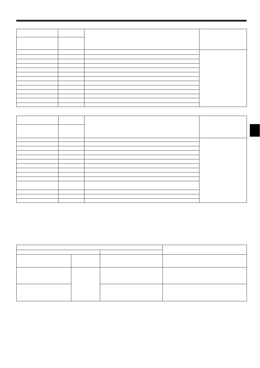
Maintenance mode operation procedures
(1) Press the
TEST
button for three seconds to
activate the maintenance mode.
(2) Press the TEMP.
buttons to set the refrigerant address.
MAINTENANCE
(3) Select the data you want to display.
MENU
ON/OFF
Compressor
information
COMP ON
x10 HOURS
COMP ON
x100 TIMES
COMP ON
CURRENT (A)
Cumulative
operation time
ON/OFF
number
Operation
current
Display A
Display B
Display A
OUTDOOR UNIT
H·EXC. TEMP
OUTDOOR UNIT
OUTLET TEMP
OUTDOOR UNIT
OUTDOOR TEMP
Heat exchanger
temperature
Comp discharge
temperature
Outdoor ambient
temperature
Display A
Outdoor unit
information
INDOOR UNIT
INLET TEMP
INDOOR UNIT
H·EXC. TEMP
INDOOR UNIT
FILTER USE H
Indoor room
temperature
Heat exchanger
temperature
Filter operation
time
Display A
Indoor unit
information
* The filter operation time displayed is the number of hours the filter has been
used since the filter reset was performed.
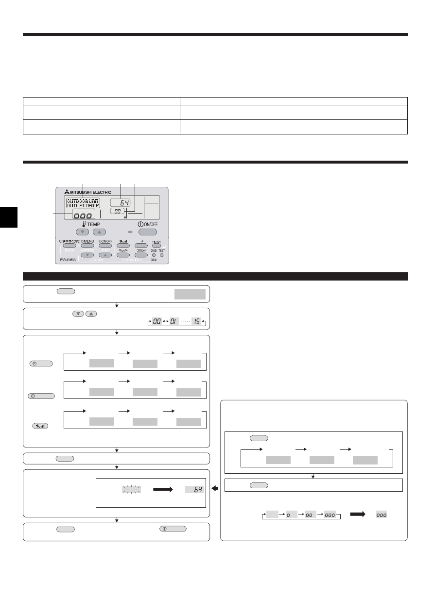
(4) Press the
FILTER
button.
(5) The data is displayed in C.
(Airflow temperature display example)
Flashing
Waiting for
response
Approx.
10 sec.
64°C
* Repeat steps (2) to (5) to check another date.
(6) Press the
TEST
button for three seconds or press the
ON/OFF
button to
deactivate the maintenance mode.
Stable operation
Using the maintenance mode, the operation frequency can be fixed and the op-
eration can be stabilized. If the air conditioner is stopped, use the following pro-
cedure to start this operation.
COOL
STABLE MODE
HEAT
STABLE MODE
STABLE MODE
CANCEL
Stable cooling
operation
Stable heating
operation
Stable operation
cancellation
Display A
Press the
MODE
button to select the operation mode.
Press the
FILTER
button.
Waiting for
stable operation
Display D
Stable
operation
10-20 min.
* You can check the data using steps (3) to (5) of the maintenance mode opera-
tion procedures while waiting for the stable operation.
8. Easy maintenance function (Option)
By using the maintenance mode, you can display many types of maintenance data
on the remote controller such as the heat exchanger temperature and compressor
current consumption for the indoor and outdoor units.
This function can be used whether the air conditioner is operating or not.
During air conditioner operation, data can be checked during either normal operation
or maintenance mode stable operation.
* This function cannot be used during the test run.
* The availability of this function depends on the connecting outdoor unit. Refer to
the brochures.
D
A
C
B
Display example (Comp discharge temperature 64°C)
Display C
On the wireless remote controller with condition above, following phenomena takes place.
• No signals from the remote controller are accepted.
• OPE lamp is blinking.
• The buzzer makes a short pipng sound.
Note:
Operation is not possible for about 30 seconds after cancellation of function selection. (Correct operation)
For description of each LED (LED 1, 2, 3) provided on the indoor controller, refer to the following table.
LED 1 (power for microcomputer)
Indicates whether control power is supplied. Make sure that this LED is always lit.
LED 2 (power for remote controller)
Indicates whether power is supplied to the remote controller. This LED lights only in the case of the
indoor unit which is connected to the outdoor unit refrigerant address “0”.
LED 3 (communication between indoor and outdoor units)
Indicates state of communication between the indoor and outdoor units. Make sure that this LED is
always blinking.
7. Test run
Wyszukiwarka
Podobne podstrony:
IM PKA RP60 71 100FAL BG79U616H01 2005
IM PKA RP60 100KAL RG79D349H01 Jul 2009
IM PCA RP50 140GA PCH P GAH BG79U614H02 2006
IM PKA RP35 50GAL BG79U615H01 2005
IM PSA RP71 140GA PSH P GAH BG79U621H01 2007
70 71 206cc pol ed02 2006
atmwp recenzja re 03 2006 id 71 Nieznany (2)
Rezolucja Pralamentu Europejskiego z 2006 96.71, delegowani
IM PUMY P100 140VHM BG79U904H02 2006
IM PCA RP HA BG79U617H01 2005
IM MSZ GA22 35 MUZ 25 35VA SG79Y421H01 GB Nov 2006
IM PKFY P63 100VFM E BG79U776H01 GB 2006
IM MUZ MSZ GB50VA SG79Y676H01 EN 2006
IM PUHZ RP200 250YHA BG79U638H01
IM PUMY P100 125 140YHM BG79U713H03 2006
IM BG79U637H01 pl PUHZ RP YHA
IM PCA RP GA BG79U614H01 2005
IM PUHZ RP200 250YHA BG79U637H03 GB 03 2007
XR 71 Sniffer PI schem PCB im
więcej podobnych podstron