
1MRS751861-MEN
Issued:
15.03.2002
Version:
A
Program revision: 4.0
We reserve the right to change data without prior notice.
Configuring MicroSCADA for DNP V3.00
Slave Protocol
Configuration Guide
COM 500
Notice 1
The information in this document is subject to change without notice and should not
be construed as a commitment by ABB. ABB assumes no responsibility for any error
that may occur in this document.
Notice 2
This document complies with the program revision 4.0.
Notice 3
Additional information such as Release Notes and Last Minute Remarks can be
found on the program distribution media.
Trademarks
Microsoft is a registered trademark of Microsoft Corporation.
Windows NT is a trademark of Microsoft Corporation.
L
ON
W
ORKS
is a registered trademark of Echelon Corporation.
Other brand or product names are trademarks or registered trademarks of their respective holders.
All Microsoft products referenced in this document are either trademarks or registered trademarks of Microsoft
Corporation.


MicroSCADA Technology Manuals
SYS 500 manuals
COM 500 manuals
Application Objects
1MRS751848-MEN
Introduction to MicroSCADA Technology
1MRS751852-MUM
JAVA-API for MicroSCADA
1MRS751851-MEN
Programming Language SCIL
1MRS751849-MEN
SCIL-API for MicroSCADA
1MRS752199-MEN
Status Codes
1MRS751850-MEN
System Configuration
1MRS751846-MEN
System Objects
1MRS751847-MEN
Configuring MicroSCADA for OPC DA Client
1MRS752246-MEN
Installation
1MRS751853-MEN
Picture Editing
1MRS751854-MEN
System Management
1MRS751857-MEN
Visual SCIL Objects
1MRS751856-MEN
Visual SCIL User Interface Design
1MRS751855-MEN
COM 500 Engineering
1MRS751858-MEN
Connecting LONWORKS Devices to MicroSCADA
1MRS751845-MEN
Communication Programming Interface (CPI)
1MRS751859-MEN
Configuring MicroSCADA for DNP V3.00 Master Protocol
1MRS751860-MEN
Configuring MicroSCADA for DNP V3.00 Slave Protocol
1MRS751861-MEN
Configuring MicroSCADA for IEC 60870-5-101 Master Protocol
1MRS751862-MEN
Configuring MicroSCADA for IEC 60870-5-101 Slave Protocol
1MRS751863-MEN
Configuring MicroSCADA for IEC 60870-5-103 Master Protocol
1MRS752012-MEN
Configuring MicroSCADA for IEC 60870-5-104 Master Protocol
1MRS751964-MEN
Configuring MicroSCADA for IEC 60870-5-104 Slave Protocol
1MRS751965-MEN
Configuring MicroSCADA for Modbus Master Protocol
1MRS752242-MEN
Configuring MicroSCADA for Modbus Slave Protocol
1MRS751864-MEN
COM 500
Configuring MicroSCADA for DNP V3.00
Slave Protocol
Configuration Guide
1MRS751861-MEN

LIB 500 manuals
LIB 510 manuals
SMS 510 manuals
CAP 505 manuals
Common manual for LIB, CAP and SMS
LIB 500 Configuration Manual
1MRS751880-MEN
LIB 500 Operator’s Manual
1MRS751885-MUM
LIB 510 Configuration
1MRS751886-MEN
LIB 510 MV Process Configuration
1MRS751887-MEN
LIB 510 MV Process Operator’s Manual
1MRS751891-MUM
LIB 510 Operator’s Manual
1MRS751888-MUM
SMS 510 Installation and Commissioning
1MRS751897-MEN
SMS 510 Operator’s Manual
1MRS751898-MUM
CAP 505 Installation and Commissioning
1MRS751901-MEN
CAP 505 Operator’s Manual
1MRS751902-MUM
Relay Configuration Tool Tutorial
1MRS751903-MEN
Relay Mimic Editor Configuration
1MRS751904-MEN
Relay Configuration Tool Quick Start Reference
1MRS751905-MEN
SPTO Configuration Tool
1MRS751906-MEN
Protocol Editing Tool
1MRS751982-MUM
Tools for Relays and Terminals
1MRS752008-MUM
1MRS751861-MEN
Configuring MicroSCADA for DNP V3.00
Slave Protocol
COM 500
Configuration Guide

1
2
3
4
1
2
3
4
COM 500
Configuring MicroSCADA for DNP V3.00
Slave Protocol
Configuration Guide
1MRS751861-MEN


COM 500
Contents
Configuration Guide
Contents:
1. Introduction ...............................................................................1
2. Safety information .....................................................................3
3. Instructions ................................................................................5
3.2.1. Base system configuration .................................................5
3.2.2. Communication system configuration ................................8
3.3. After configuration .......................................................................31
3.4. How to test the configuration .......................................................32
3.5. Serial cable wiring diagram .........................................................33
4. Technical description .............................................................35
4.1.1. DNP V3.00 protocol .........................................................35
4.1.2. Level of implementation ...................................................35
4.1.3. Supported process object types .......................................38
4.2. Communication ...........................................................................39
4.2.1. Protocol converter ............................................................39
4.2.2. Communication modes ....................................................40
4.2.3. Handshaking ....................................................................40
4.2.4. DNP3.0 in LAN/WAN .......................................................40
4.2.5. Addressing .......................................................................41
4.2.6. Internal indications ...........................................................41
4.2.7. Data flow ..........................................................................42
4.2.8. Device communication attributes .....................................44
4.3. Command procedures .................................................................49
4.3.1. Command procedures in COM 500 .................................49
4.3.2. Command procedures in SYS 500 ..................................50
4.3.2.1. Command procedures for process data .............50
4.3.2.2. Command procedures for the status of output
objects ................................................................54
4.3.2.3. Command procedures for initialising the NET
database ............................................................54
4.3.2.4. Command handling in DNP V3.00 protocol .......56
4.3.2.5. Command procedures for data commands ........56
4.3.2.6. Command procedures for application and system
commands ..........................................................59
1MRS751861-MEN
Configuring MicroSCADA for DNP V3.00
Slave Protocol

1MRS751861-MEN
Configuring MicroSCADA for DNP V3.00
Slave Protocol
COM 500
Contents
Configuration Guide
4.6. Device profile .............................................................................. 63

1MRS751861-MEN
COM 500
1
Configuring MicroSCADA for DNP V3.00
Slave Protocol
Configuration Guide
1. Introduction
1
1.
Introduction
Using this manual
This manual should be read when you want to use the DNP V3.00 slave protocol and
need information related to it. It describes how to configure the base system and the
communication system to establish communication to a DNP master.
In addition to this configuration, the base system needs to be configured for the
process communication. For information about this subject, refer to other manuals,
for example Application Objects manual or COM 500 Engineering manual. The
DNP master needs to be configured as well.
Referenced manuals
The following COM 500 manuals should be available for reference during the use
of this manual:
• Configuring MicroSCADA for DNP V3.00 Master Protocol manual
• COM 500 Engineering manual
The following MicroSCADA manuals should be available for reference during the
use of this manual:
• System Configuration manual
• System Objects manual
• Application Objects manual
Other referenced manuals
The following documents of the DNP V3.00 protocol are available via the DNP
Users Group:
• DNP V3.00 DATA LINK LAYER
• DNP V3.00 APPLICATION LAYER
• DNP V3.00 DATA OBJECT LIBRARY
• DNP V3.00 TRANSPORT FUNCTIONS
• DNP V3.00 SUBSET DEFINITIONS
1MRS751861-MEN
2
1MRS751861-MEN
Configuring MicroSCADA for DNP V3.00
Slave Protocol
COM 500
1. Introduction
Configuration Guide
DNP slave
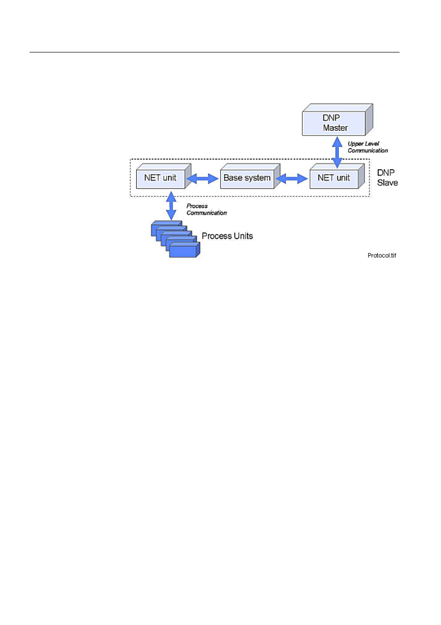
DNP V3.00 slave protocol is mainly used for upper level communication between
COM 500 or SYS 500 and a NCC as illustrated by Figure 1.-1:
)LJ 7KH'130DVWHUVHHVWKH1(7XQLWDQGWKHSURFHVVEHKLQGLWDVDVODYH
The data from the process activates certain event channels and command procedures
in the base system. This command procedure sends the information forward to the
NET unit and the DNP master.

1MRS751861-MEN
COM 500
3
Configuring MicroSCADA for DNP V3.00
Slave Protocol
Configuration Guide
2. Safety information
2. Safety
information
This chapter gives information about the prevention of hazards.
2.1.
Backup copies
We suggest that you take backup copies before making any changes, especially the
ones that might have side effects. Software and data need to be copied to another
place, usually to a CD or backup tape. A writable CD and DAT tape are commonly
used.
Backup copying makes it easier to restore application software in case of a disk crash
or any other serious failure when stored data is lost. Therefore, it is recommended
that backup copies are taken regularly.
There should be at least two system backup copies and two application copies. A
new backup is copied over the oldest backup. This way the latest version is always
available, even if the backup procedure fails.
Detailed information on how to take backup copies should be delivered to the
customer with the application.
System backup
Usually a system backup is taken after the application is made. A backup should be
taken again when changes are made to the MicroSCADA system. For example, if
the driver configuration or the network set-up is changed.
Application backup
An application backup is taken simultaneously with the system backup after the
application is made. A backup should be taken again when changes are made to the
application. For example, if pictures or databases are edited or new pictures are
added.
2.2.
Fatal errors
A fatal error is an error that causes a break-down or a locked situation in the
MicroSCADA program execution.
Handling
In case of a fatal error:
Write down the possible MicroSCADA error messages.
Shut down the MicroSCADA main program. If this cannot be done in the
MicroSCADA Control Panel, try to end the task in Windows NT™
1
Task
Manager.
1. Windows NT is a trademark of Microsoft Corporation.
1MRS751861-MEN
Configuring MicroSCADA for DNP V3.00
Slave Protocol

4
1MRS751861-MEN
Configuring MicroSCADA for DNP V3.00
Slave Protocol
COM 500
2. Safety information
Configuration Guide
Shutting down the base system computers by switching off the power might
damage the files.
In Windows NT, the data kept in the main memory at the moment of a fatal error
is placed in the drwtsn32.log file. It is placed in a system folder, for example,
Winnt. Analyse and copy the data in this file.
Restart the system.
Report the program break-down together with the possible MicroSCADA error
messages and the information from the drwtsn32.log file to the MicroSCADA
supplier.
Status codes
Error messages in SCIL are called status codes. A list of status codes and short
explanations can be found in the Status Codes manual.

1MRS751861-MEN
COM 500
5
Configuring MicroSCADA for DNP V3.00
Slave Protocol
Configuration Guide
3. Instructions
3
3.
Instructions
Communication
In MicroSCADA DNP V3.00 slave protocol is implemented only in the PC-NET
software. PC-NET unit communicates over an INTEGRATED link and via the serial
ports of the base system computer. Setting the attributes of MicroSCADA system
objects can modify the communication parameters.
The base system considers each DNP slave device as a station that has been created
to a line of a NET unit. Each DNP station works as a protocol converter that converts
data between the internal protocol of MicroSCADA and DNP V3.00 protocol.
3.1.
Installation
Software requirements
The following software is required:
• MicroSCADA 8.4.3 Software (or newer)
• Operating system - Windows NT
Install the software as described in their respective manuals. Installation of
MicroSCADA 8.4.3 software is described in the MicroSCADA Installation manual.
Revision information
The information given in this document is valid for MicroSCADA revision 8.4.4.
With the following limitations the information is valid in older revisions:
• Dial-up was implemented in revision 8.4.4
3.2.
Configuration
General
The configuration can be divided into two parts:
• Base system configuration
• Communication system configuration
3.2.1.
Base system configuration
General
Each base system has a set of objects that specify the base system and its
environment, hardware and software, as well as the physical and logical connections
of the base system and its applications.
The base system objects are defined with SCIL commands in the
SYS_BASCON.COM file, which is executed every time the base system is started.
Except for a few limitations, you can also define and modify the base system objects
any time when MicroSCADA is running. During the operation, the base system
objects are in the primary memory of the base system computer.
1MRS751861-MEN

6
1MRS751861-MEN
Configuring MicroSCADA for DNP V3.00
Slave Protocol
COM 500
3. Instructions
Configuration Guide
DNP V3.00 slave protocol is implemented in the PC-NET software, which means
that an INTEGRATED link must be used. When an integrated link is used, the base
system and PC-NET use services provided by the operating system for exchanging
information. DNP V3.00 slave protocol uses the station type 30 with DNP process
database interface.
Configuration steps
To configure SYS_BASCON.COM:
Define the base system.
Define a link.
Define a node.
Define a monitor.
Define an application.
Define the station type.
Define the DNP stations.
The definitions are made in the example below using the old SYS_BASCON.COM
template. If the new (revision 8.4.2 or later) template is used, the INTEGRATED
link and the node for the PC-NET is created by the System Configuration Tool and
need not to be included in SYS_BASCON.COM. For more information on the
system objects, see the System Objects manual.
([DPSOHRI6<6B%$6&21&20
The following is an example of SYS_BASCON.COM file for communication with
the DNP V3.00 slave protocol. An application DNP_TEST is defined. In this
example two DNP slave stations are configured.
;***************************************************************************
;
; SYS_BASCON.COM
; BASE SYSTEM CONFIGURATION TEMPLATE
;
;***************************************************************************
#CREATE SYS:B = LIST(-
SA = 209,- ;STATION ADDRESS OF BASE SYSTEM
ND = 9,- ;NODE NUMBER OF BASE SYSTEM
DN = 3,- ;DEFAULT NET NODE NUMBER
DS = "RTU",- ;STA TYPES: E.G. STA,RTU,SPA,REX
FS = "NEVER") ;FILE SYNCH CRITERIA:
;NEVER,MAINT,SET,CHECKPOINT,ALWAYS
;***************************************************************************
;
; COMMUNICATION LINKS
#CREATE LIN:V = LIST(- ;REQUIRES THE PC-NET PROGRAM
LT = "INTEGRATED",-
SC = "\SC\PROG\PC_NET\PC_NETS.EXE") ;STARTUP COMMAND
#CREATE LIN3:B = %LIN

1MRS751861-MEN
COM 500
7
Configuring MicroSCADA for DNP V3.00
Slave Protocol
Configuration Guide
3. Instructions
3
;***************************************************************************
;
; COMMUNICATION NODES
#CREATE NOD:V = LIST(-
LI = 3,-
SA = 203)
#CREATE NOD3:B = %NOD
;***************************************************************************
;
; PRINTERS
;***************************************************************************
;
; MONITORS
#LOOP_WITH I = 1..5
#CREATE MON’I’:B = LIST(-
TT = "LOCAL",- ;TRANSLATION TYPE
DT = "X") ;X MONITOR
@MON_MAP(%I) = -1
#LOOP_END
#LOOP_WITH I = 6..10
#CREATE MON’I’:B = LIST(-
TT = "LOCAL",- ;TRANSLATION TYPE
DT = "VS") ;VISUAL SCIL MONITOR
@MON_MAP(%I) = -1
#LOOP_END
;***************************************************************************
;
; APPLICATIONS
#CREATE APL:V = LIST(-
TT = "LOCAL",- ;TRANSLATION TYPE
NA = "DNP_TEST",- ;NAME OF APPLICATION DIRECTORY
AS = "HOT",- ;APPLICATION STATE: COLD,WARM,HOT
HB = 2000,- ;HISTORY BUFFER SIZE)
RC = VECTOR("FILE_FUNCTIONS_CREATE_DIRECTORIES"),-
AP = (1,2),-
MO = %MON_MAP,- ;MONITOR MAPPING
PR = (1,2,3)) ;PRINTER MAPPING
#CREATE APL1:B = %APL
;***************************************************************************
; STATION TYPES
#SET STY30:BCX = "DNP"
;***************************************************************************
; STATIONS
;*** NET 3 stations ***
#CREATE STA:V = LIST(-
TT = "EXTERNAL",-
ST = "DNP",-
ND = 3,-
TN = 1)
#CREATE STA1:B = %STA

8
1MRS751861-MEN
Configuring MicroSCADA for DNP V3.00
Slave Protocol
COM 500
3. Instructions
Configuration Guide
#CREATE STA:V = LIST(-
TT = "EXTERNAL",-
ST = "DNP",-
ND = 3,-
TN = 2)
#CREATE STA2:B = %STA
;***************************************************************************
3.2.2.
Communication system configuration
General
Each NET unit contains a set of system objects, which specify line properties,
connected devices etc. These objects can be created, modified and deleted by SCIL,
and setting the attributes of the objects can change the properties. This
communication system configuration is usually done by using command
procedures.
Access to the attributes can be one of the following:
•
5HDGRQO\: The attribute can only be read. There are still a few exceptions in
which the values can be reset.
•
:ULWHRQO\: The attribute can only be written (set).
•
5HDGFRQGLWLRQDOZULWHThe attribute can be both read and written, but the
object must be set out of use (IU = 0) before writing.
•
1ROLPLWDWLRQV: The attribute can be both read and written without limitations.
The implementation of DNP V3.00 slave protocol in MicroSCADA can be divided
into two layers: link layer and application layer. Both of these layers have a specific
functionality and a set of attributes of their own. The link layer corresponds to a line
of a NET unit and the application layer corresponds to a station configured to the
line.
The purpose of the communication system configuration is to:
• Create all the system objects needed to establish communication between the
master and the slave.
• Adjust the values of the system object attributes to match the physical
communication channel and the properties of the master station.
Setting the attribute values
All the line and station attributes have sensible default values but the value of each
attribute must be checked against the requirements of the actual communication
system. The attribute values depend on:
• The physical communication media (e.g. leased telephone line, radio link, power
line carrier). This affects in particular the attributes of the DNP line such as the
baud rate and parity.
• The network topology used (point-to-point, multi-drop). This affects for example
the link type.
• The size (number of stations) of the system. This affects especially the timeout
parameters; the slower the media and bigger the system, the longer timeouts are
needed.
1MRS751861-MEN
COM 500
9
Configuring MicroSCADA for DNP V3.00
Slave Protocol
Configuration Guide
3. Instructions
3
• The master system. This affects both the line and station attributes, and also the
message types used.
When making the DNP connection, an agreement about the used communication
parameters should be made with the supplier or owner of the master system.
Network topologies
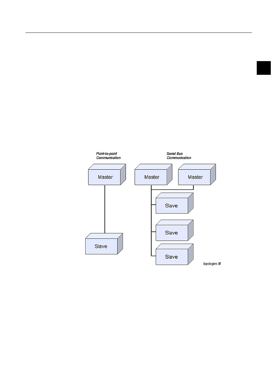
The implementation of the DNP V3.00 protocol in MicroSCADA supports direct
and serial bus topologies. The direct topology (point-to-point) can be a direct
physical cable from point-to-point or a two-node radio, or modem network. The
serial bus topology (multi-drop) is commonly made up of many modems with their
outputs/inputs tied together, or using a star-coupler.
DNP link layer supports the multiple-master, multiple-slave and peer-to-peer
communication methods. In peer-to-peer communication, all the stations act as slave
data links and collisions are possible as no station has a higher priority and all of
them can transmit spontaneously. MicroSCADA uses random delay of
retransmission as a collision avoidance method. Figure 3.2.2.-1 illustrates the
network topologies.
)LJ
1HWZRUNWRSRORJLHV
DNP V3.00 link layer
The line process of a NET unit performs the functions of the link layer. The purpose
of the link layer is to send and receive messages with external devices by using DNP
V3.00 protocol. By using DNP terminology this means that the data link layer
provides transfer of Link Service Data Units (LSDU) across the physical link.
LSDUs are user data fragments small enough to fit to the FT3 frame format. The
application layer of a NET unit is responsible for assembling and disassembling
messages into LSDUs. The link layer provides frame synchronisation and link
control.

10
1MRS751861-MEN
Configuring MicroSCADA for DNP V3.00
Slave Protocol
COM 500
3. Instructions
Configuration Guide
According to DNP V3.00 documentation, the link layer performs the following
functions:
• Exchange of LSDUs between peer DNP data links.
• Error notification to data link user.
• Sequencing of LSDUs.
• Priorities LSDU delivery.
• Quality LSDU delivery.
• Performing message retries.
• Synchronising and handling of the Frame Count Bit in the control word.
• Setting and clearing the Data Flow Control bit based on buffer availability.
• Packing user data into the defined frame format and transmitting the data to the
physical layer.
• Unpacking the frames that are received from the physical layer into user data.
• Controlling all aspects of the physical layer.
• Responding to all valid frames (function codes) received from the physical layer.
Link layer attributes
The following attributes can be used for configuring DNP V3.00 slave lines in
MicroSCADA.
,8
,Q8VH
Indicates whether the line is in use (value 1) or not in use (value 0).
Data type:
Integer
Value:
0 or 1
Index range:
1...8 (NET line numbering)
Default value:
0
Access: No
limitations
32
3URWRFRO
The data transfer protocol used on the line. The line is defined to the NET by setting
this attribute. By setting the attribute to 0 the line definition including all the line
attributes are deleted.
Data type:
Integer
Value:
0...35
35, value with DNP V3.00 slave protocol
Index range:
1...8 (NET line numbering)
Access:
Read, conditional write
6'
6\VWHP'HYLFH1DPH
Associates the NET line numbers of PC-NET with the device names of the physical
channels of the serial ports.

1MRS751861-MEN
COM 500
11
Configuring MicroSCADA for DNP V3.00
Slave Protocol
Configuration Guide
3. Instructions
3
By default, line number 1 is connected to COM1, line 2 to COM2 and so on. By
using the SD attribute it is possible to override these default values. This may be
necessary if COM ports will be used as NET lines or if, for example, a RocketPort
card is used.
Data type:
Text
Value:
See above
Index range:
1...8 (NET line numbering)
Access: Read,
conditional
write
When using DNP 3.0 over LAN, the SD attribute defines the used connection type.
Possible types are TCP and UDP.
#SET NET’NET’:SSD’LINE’ = “TCP”;line uses TCP connection
#SET NET’NET’:SSD’LINE’ = “UDP”;line uses UDP connection
36
%XIIHU3RRO6L]H
Specifies the number of message buffers reserved for the line. Each buffer can
contain one message. The maximum data content length of a message is 228 bytes.
Data type:
Integer
Value:
1...250
Index range:
1...8 (NET line numbering)
Default value:
20
Access:
Read, conditional write
%5
%DXG5DWH
Transmission rate used on the line.
Data type:
Integer
Value:
1...19200
Unit:
Bits / s
Index range:
1...8 (NET line numbering)
Default value:
1200
Access: Read,
conditional
write
3<
3DULW\
Specifies the parity check (if any) used for the characters transferred on the line.
Data type:
Integer
Value:
0 = no parity check
1 = odd parity
2 = even parity
Index range:
1...8 (NET line numbering)
Default value:
2
Access: Read,
conditional
write

12
1MRS751861-MEN
Configuring MicroSCADA for DNP V3.00
Slave Protocol
COM 500
3. Instructions
Configuration Guide
5'
5HFHLYHU'DWD%LW&RXQW
Specifies the number of data bits in each received character.
Data type:
Integer
Value:
5, 6, 7 or 8
Unit:
Data bits
Index range:
1...8 (NET line numbering)
Default value:
8
Access:
Read, conditional write
6%
6WRS%LWV
Specifies the number of stop bits attached to each transmitted character.
Data type:
Integer
Value:
1 or 2
Unit:
Stop bits
Index range:
1...8 (NET line numbering)
Default value:
1
Access:
Read, conditional write
7'
7UDQVPLWWHU'DWD%LW&RXQW
Specifies the number of data bits in each transmitted character.
Data type:
Integer
Value:
5, 6, 7 or 8
Unit:
Data bits
Index range:
1...8 (NET line numbering)
Default value:
8
Access:
Read, conditional write
3'
3ROO'HOD\
Delay (in milliseconds) between test function of link commands. The purpose of this
command is to ensure that the communication to the master is open. If this attribute
is set to zero, the test function of link command is not sent.
Data type:
Integer
Value:
0...65535
Unit:
Milliseconds
Index range:
1...8 (NET line numbering)
Default value:
500
Access:
Read, conditional write
0/
0D[LPXP0HVVDJH/HQJWK
Maximum length of a data link fragment (LPDU). This length is the amount of user
data without checksums.

1MRS751861-MEN
COM 500
13
Configuring MicroSCADA for DNP V3.00
Slave Protocol
Configuration Guide
3. Instructions
3
Data type:
Integer
Value:
50...249
Index range:
1...8 (NET line numbering)
Default value
230
Access: No
limitations
;5
0D[LPXP5DQGRP'HOD\IRU5HWUDQVPLVVLRQ
Random transmission delay is a simple collision avoidance method used in DNP
lines. When unsolicited responses are enabled for slave stations on a multi-drop line,
there is a possibility that several slave devices send messages at the same time. This
message collision is seen as timeout in a slave station since the master is not
responding. The XR attribute limits the possibility that two devices retransmit
messages at the same time.
This attribute can also be used for setting the priorities of the slave stations: the
station with the smallest retransmission delay has the highest priority.
Data type:
Integer
Value:
0...65535
Unit:
Milliseconds
Index range:
1...8 (NET line numbering)
Default value:
0
Access:
No limitations
'(
&76'HOD\
Time delay (in milliseconds) between the activation of the RTS signal (Request to
Send) and the start of a new transmission.
Data type:
Integer
Value:
0...65535
Unit:
Milliseconds
Index range:
1...8 (NET line numbering)
Default value
50
Access:
Read, conditional write
7:
7UDQVPLVVLRQ:DLW'HOD\
Specifies the transmission delay in milliseconds, i.e., the time that the NET must
wait after receiving a CTS (Clear to Send) signal until starting the transmission of a
message.
Data type:
Integer
Value:
0...65535
Unit:
Milliseconds
Index range:
1...8 (NET line numbering)
Default value:
5
Access: No
limitations

14
1MRS751861-MEN
Configuring MicroSCADA for DNP V3.00
Slave Protocol
COM 500
3. Instructions
Configuration Guide
+7
+HDGHU7LPHRXW
Specifies the maximum waiting time in milliseconds within which the first byte of
a link layer response from the external device should have been received after the
transmission of a message. If no response has been received within this time, new
attempts are performed the number of times specified by the Enquiry limit. If still
no response is obtained, the station is suspended.
Data type:
Integer
Value:
0...65535
Unit:
Milliseconds
Index range:
1...8 (NET line numbering)
Default value:
2000
Access:
Read, conditional write
7,
5HVSRQVH7LPHRXW
The time in seconds that the DNP link waits for the end of the received message.
Data type:
Integer
Value:
0...255
Unit:
Seconds
Index range:
1...8 (NET line numbering)
Default value:
2
Access: No
limitations
5.
576.HHSXS3DGGLQJ&KDUDFWHUV
The number of padding characters (null characters) inserted to the end of telegram
to delay the passivation of the RTS (Request To Send) signal.
Data type:
Integer
Value:
0...255
Index range:
1...8 (NET line numbering)
Default value:
0
Access:
Read, conditional write
5,
5HFHLYH,QWHUUXSW(QDEOH'HOD\
Defines the delay in milliseconds after which the receiver of a NET line is enabled
after a message has been issued.
Data type:
Integer
Value:
0...255
0 = receiver is always enabled
Unit:
Milliseconds
Index range:
1...8 (NET line numbering)
Default value:
0
Access: No
limitations

1MRS751861-MEN
COM 500
15
Configuring MicroSCADA for DNP V3.00
Slave Protocol
Configuration Guide
3. Instructions
3
(1
(QTXLU\/LPLW
Specifies the maximum number of times that a message is retransmitted after a
timeout.
Data type:
Integer
Value:
1...255
Index range:
1...8 (NET line numbering)
Default value:
1
Access:
Read, conditional write
6*
0RGHP6LJQDO
An attribute for direct supervision and control of the state of the modem signal. The
attribute applies to all protocols. It is used for diagnostics and testing.
Data type:
Integer
Value:
0 = Passive signal
1 = Active signal
Index range:
100 * line no + signal no. Signal no. 5 = CTS, 8 = DCD,
20 = DTR
Access: Read-only
0,
0HVVDJH,GHQWLILFDWLRQ
Object address of system messages.
Data type:
Integer
Value:
1...32760
Index range:
1...8 (NET line numbering)
Default value:
6000 + (100 * NET number) + line number
Access: Read,
conditional
write
06
0HVVDJH$SSOLFDWLRQ
The number of the application that is the receiver of the system messages generated
by the line.
Data type:
Integer
Value:
1...32
Default value:
1
Index range:
1...8 (NET line numbering)
Access:
Read, conditional write
([DPSOH
In the example of SYS_BASCON.COM earlier in this chapter, the number of the
message application is 1.
/.
/LQN7\SH
The type of data link connection used on the line:

16
1MRS751861-MEN
Configuring MicroSCADA for DNP V3.00
Slave Protocol
COM 500
3. Instructions
Configuration Guide
Data type:
Integer
Value:
14: Collision detection in use, transmission when the Data
Carrier Detect (DCD) signal of the line is not set.
15: No collision detection, Data Carrier Detect signal (DCD) is
handled as in other protocols.
Index range:
1...8 (NET line numbering)
Default value:
15
Access:
Read, conditional write
/$
/LQN/D\HU&RQILUPDWLRQV(QDEOHG
Determines whether the link layer confirmations are in use (value 1) or not in use
(value 0).
Data type:
Integer
Value:
0 or 1
Index range:
1...8 (NET line numbering)
Default value:
1
Access:
Read, conditional write
'&
'LDJQRVWLF&RXQWHUV
The line protocols gather statistical information about the events on the lines by
incrementing a number of diagnostic counters. All the major events and error
situations of the communication have their own counters.
When accessing diagnostic counters, the attribute is indexed according to the
formula:
100 * (line number) + (diagnostic counter number)
DNP V3.00 slave protocol supports the following counters:
1. Transmitted telegrams
2. Failed transmissions
4. Transmitted commands
5. Transmitted replies
11. Received messages
12. Parity errors
13. Overrun errors
14. Check sum errors
15. Framing errors
16. Buffer overflow errors
21. TCP/UDP connect
22. TCP/UDP accept
23. TCP/UDP close
Data type:
Integer
Value:
0...30000
Index range:
See above
Access:
Read-only, the values can be reset

1MRS751861-MEN
COM 500
17
Configuring MicroSCADA for DNP V3.00
Slave Protocol
Configuration Guide
3. Instructions
3
DNP V3.00 application layer
The main purpose of the application layer is protocol conversion between DNP and
the internal protocol of MicroSCADA. The application layer also takes care of the
application level communication with the master.
STA objects created in a NET unit perform the functions of the application layer.
Several STA objects of the DNP device type are allowed on the same line. Some
application layer attributes are used for configuration of the station, others are used
for device communication. The configuration attributes are presented in this chapter
and the device communication attributes in Chapter 4. By using the device
communication attributes you can send messages and, for example, reset queues on-
line.
Application layer attributes
The following attributes can be used for configuring the DNP slave stations in
MicroSCADA.
,8
,Q8VH
Indicates whether the station is in use (value 1) or not in use (value 0).
Data type:
Integer
Value:
0 or 1
Default value:
0
Access:
No limitations
/,
/LQH1XPEHU
The number of the NET line the station is connected to.
Data type:
Integer
Value:
1...8
Default value:
1
Access:
Read, conditional write
!
Setting this attribute is not needed when the station is created by using the DV
attribute.
6$
6ODYH$GGUHVV
The station address of the DNP slave station.
Data type:
Integer
Value:
0...65534
Access:
Read, conditional write
([DPSOH
In the example of the communication system configuration, the slave addresses are
1 and 2.

18
1MRS751861-MEN
Configuring MicroSCADA for DNP V3.00
Slave Protocol
COM 500
3. Instructions
Configuration Guide
0$
0DVWHU$GGUHVV
The station address of the master station, the destination address of the unsolicited
messages sent by the slave.
Data type:
Integer
Value:
0...65534
Access:
Read, conditional write
,$
,QWHUQHW$GGUHVV
The IP address or the hostname of the remote host. The connection is established
with a device in this address using port number 20000. The line must be taken into
use at least once before writing to this attribute. If routers/firewalls are used, it must
be ensured that the defined port number is left open for connection.
Value:
Any string, max 29 characters
Access:
Read/write
This attribute accepts the IP address in form:
#SET STA1:SIA=”62.236.144.120”
or as an alias name:
#SET STA1:SIA=”GRACE”
When an alias name is used, it must be defined in the TCP host file
%windir\system32\drivers\etc\hosts
There is one exception in the usage of the IA attribute. When operating as a DNP
master in the UDP mode and there is more than one STA objects, i.e. the
configuration is a multidrop configuration, a unique local port number must be
defined for the other station but the first one. This is done in the following way:
;first sta uses local port 20000
#SET STA1:SIA=”62.236.144.120”
;second STA uses local port 19999
#SET STA2:SIA=”19999>62.236.144.121”
;third STA uses local port 19998
#SET STA3:SIA=”19998>62.236.144.122”
The local port numbers are freely selectable, but they are not allowed to be used by
any other application.
$/
$OORFDWLRQ
Allocates the station to an application. When the AL attribute has the value 1, the
station is reserved by the application specified by the AS attribute. All the
spontaneous messages from the station will be sent to this application.
Data type:
Integer
Value:
0 or 1
Access:
No limitations

1MRS751861-MEN
COM 500
19
Configuring MicroSCADA for DNP V3.00
Slave Protocol
Configuration Guide
3. Instructions
3
$6
$OORFDWLQJ$SSOLFDWLRQ
Specifies the allocating application of the station (see the AL attribute). The
allocating application will get all the spontaneous process data from the station. This
application is also the only one that is allowed to set the device communication
attributes.
Data type:
Integer
Value:
0...32, 0 = no application
Access:
Read-only
!
When the AL attribute is set to 0, AS also gets the value 0.
0,
0HVVDJH,GHQWLILFDWLRQ
Object address of system messages.
Data type:
Integer
Value:
1...32760
Default value:
30000 + STA object number
Access: Read,
conditional
write
06
0HVVDJH$SSOLFDWLRQ
The number of the application that is the receiver of the system messages generated
by the station.
Data type:
Integer
Value:
1...32
Default value:
1
Access: Read,
conditional
write
([DPSOH
In the example of SYS_BASCON.COM earlier in this chapter, the number of the
message application is 1.
6(
6\VWHP0HVVDJHV(QDEOHG
Specifies whether the system messages generated by NET and related to the station
are sent to applications (value 1) or not (value 0). By using this attribute, it is
possible to disable the system messages related to the station.
Data type:
Integer
Value:
0 or 1
Default value:
1
Access: No
limitations

20
1MRS751861-MEN
Configuring MicroSCADA for DNP V3.00
Slave Protocol
COM 500
3. Instructions
Configuration Guide
,/
,QIRUPDWLRQ$GGUHVV/HQJWK
The length of data object address (index) used in the DNP messages.
Data type:
Integer
Value:
1 or 2
Unit:
Octets
Default value:
2
Access:
Read, conditional write
3&
3URFHVV'DWD&RQILUPDWLRQ
By setting the value of this attribute to 0, application level confirmations can be
disabled, and by setting the value to 1, the confirmations can be enabled. In the
following cases the DNP slave station sets the confirmation request of a data
fragment on, regardless of the value of the PC attribute:
• The sent data fragment contains event data.
• The response message consists of multiple data fragments.
Data type:
Integer
Value:
0, 1 or 2
Default value:
1 (application level confirmations enabled)
Access:
Read, conditional write
The station configuration PC=0 will disable the application layer confirmations in
most cases, but multifragment messages or messages containing event data will still
request for the application layer confirmation. This implementation follows the
recommendation in the DNP3.0 standard. A special value PC=2 is provided to
disable the application layer confirmations also with these messages.
$5
$SSOLFDWLRQ0HVVDJH'DWD5HWULHV
The maximum number of retransmissions of an application data fragment (APDU).
Data type:
Integer
Value:
0...5
Default value:
0
Access: No
limitations
0/
0D[LPXP0HVVDJH/HQJWK
The maximum length of an application data fragment (APDU).
Data type:
Integer
Value:
249...2048
Unit:
Octets
Default value:
2048
Access:
No limitations

1MRS751861-MEN
COM 500
21
Configuring MicroSCADA for DNP V3.00
Slave Protocol
Configuration Guide
3. Instructions
3
7&
7LPH6\QFKURQLVDWLRQ
Determines the behaviour of the slave device when it receives a time
synchronisation message as follows:
Data type:
Integer
Value:
0 = the synchronisation message is handled and the clock of the
base system is set to the received time.
1 = The message is acknowledged (positive acknowledgement),
but the clock of the base system is not set. The slave station never
sets the “time synchronisation needed” bit in its responses.
2 = The message is acknowledged (negative acknowledgement),
but the clock of the base system is not set. The slave station never
sets the “time synchronisation needed” bit in its responses.
Default value:
0
Access:
No limitations
&$
&RPPDQG$GGUHVV
The object address of bitstream process object in the MicroSCADA process
database, where the slave device sends unidentified messages. If the value of the CA
attribute is 0, the unidentified messages are not sent and the bitstsream object is not
updated.
Data type:
Integer
Value:
0...65534
Default value:
0 (unidentified messages not sent)
Access: No
limitations
!
The unit number of the bit stream process object must be the same as the STA object
number of the slave station.
'5
'LUHFWLRQ
States if the DNP slave station acts as the station A (primary station) or station B
(secondary station).
Data type:
Integer
Value:
0 or 1
Default value:
0 (secondary station)
Access:
Read, conditional write
5:
5HSO\:LQGRZ6L]H
Defines how many data items (e.g. single point values, analog values) can be written
from the base system to NET without a reply or request from the master. If the slave
station cannot send data items spontaneously to the master, it stores data into local

22
1MRS751861-MEN
Configuring MicroSCADA for DNP V3.00
Slave Protocol
COM 500
3. Instructions
Configuration Guide
buffers and creates a local reply to the base system and the execution of the SCIL
program can continue. The slave station stores items until the number of items in
local buffers is equal to RW. After that the slave station delays the replies to the base
system until the number of items drops below RW again (data sent to master and
reply received). This delay is configurable and it is defined by the MT attribute.
Data type:
Integer
Value:
0...500
Default value:
100
Access:
No limitations
50
5XQQLQJ0RGH
Consists of a set of flags that control the behaviour and functionality of the DNP
slave station. Each flag is one bit of this attribute. The bits are as follows:
Bit 0:
Sending messages while waiting for a confirmation. When this
bit is 0 the sending of a new message other than confirmation
may not be started, if the DNP slave station is waiting for a
confirmation from a remote station. The message, other than
confirmation, may be e.g. a response to a request. When this bit
is 1, the sending of a new APDU (other than confirmation) may
be started, althought the STA object is waiting for a confirmation
from the master.
Bit 1:
Variations in response messages. When this bit is 0, NET uses
dynamic variations in response messages. Variations depend on
the status flags of the data object and they can vary between with
and without status types. When this bit is 1, the variations are
fixed. The NET unit replies always with the same variation that
was in the master’s request.
Bit 2:
Address offset usage in command receiving. When this bit is 0,
no address offset is used. The address/index of the object in
command is used “as it is” in process object updating. Thus, the
address of the process object in the database and the address of
the incoming object are equal. When this bit is 1, an offset
TYPE*(2^24) is added to address/index of the incoming object
and the process objects must be created with these addresses.
The possible TYPEs are 12 (Control relay output block) and 41
(Analog output block).
Data type:
Integer
Value:
1...65535
Access:
No limitations
'&
'LDJQRVWLF&RXQWHUV
The values of the diagnostic counters which the NET unit keeps for the station. The
counters have the following meaning:
1. Suspension information (0 = OK, 1 = suspended)
2. Suspension counter

1MRS751861-MEN
COM 500
23
Configuring MicroSCADA for DNP V3.00
Slave Protocol
Configuration Guide
3. Instructions
3
3. Transmitted data messages
4. Transmitted command messages
5. Transmitted confirmation messages
6. Received data messages
7. Received command messages
8. Received confirmation messages
9. Received unknown messages
10. APDU in queue length
11. APDU out queue length
12. TSDU in queue length
13. TSDU out queue length
14. WAIT CONFIRM queue length
15. SYS transition queue length
16. Confirmation transition queue length
17. Select transition queue length
18. Free APDUs queue length
19. Free events queue length
20. Free SYS transitions queue length
Data type:
Integer
Value:
1...65535
Index range:
1...20
Access:
Read-only, the values can be reset
26
2EMHFW6WDWXV
The current object status of the DNP slave station. When value 1 is written to this
attribute, the slave station retransmits its current status code.
Data type:
Integer
Value:
0 or 1
Access:
No limitations
,1
,QWHUQDO,QGLFDWLRQV
The current value of the internal indications of the DNP slave station. See the DNP
protocol documentation for details of the internal indications.
Data type:
Integer
Value:
0...65535
Access:
Read-only
&7
&RQILUPDWLRQ7LPHRXW
The maximum time in seconds that the slave station waits for an application layer
confirmation from the master.
Data type:
Integer
Value:
0...600

24
1MRS751861-MEN
Configuring MicroSCADA for DNP V3.00
Slave Protocol
COM 500
3. Instructions
Configuration Guide
Unit:
Seconds
Default value:
10
Access:
No limitations
77
7UDQVSRUW/D\HU7LPHRXW
The maximum time in seconds that the transport layer is allowed to assemble one
application message fragment.
Data type:
Integer
Value:
0...600
Unit:
Seconds
Default value:
10
Access: No
limitations
67
6<6:DLWLQJ7LPH
The maximum time in milliseconds that the slave station waits for a reply from the
base system.
Data type:
Integer
Value:
0...60000
Unit:
Milliseconds
Default value:
5000
Access: No
limitations
07
0D[LPXP'HOD\HG5HVSRQVH7LPH
The maximum time in seconds to delay a response for writing data to the SD and EV
attributes, if the number of items in the queue is greater than the value of the RW
attribute.
Data type:
Integer
Value:
0...600
Unit:
Seconds
Default value:
15
Access:
No limitations
57
5HSO\7LPHRXW
The maximum time in seconds that the DNP application layer waits for a reply from
the master.
Data type:
Integer
Value:
0...600
Unit:
Seconds
Default value:
10
Access:
No limitations

1MRS751861-MEN
COM 500
25
Configuring MicroSCADA for DNP V3.00
Slave Protocol
Configuration Guide
3. Instructions
3
(7
([HFXWH:DLWLQJ7LPH$IWHU6HOHFW
The maximum time in seconds that the slave waits for an execute command after
receiving an operate command.
Data type:
Integer
Value:
0...600
Unit:
Seconds
Default value:
30
Access:
No limitations
Autodialling attributes
MicroSCADA provides support for the autocaller functionality for the DNP slave
protocol. An autocaller is a modem with functions for automatic dial-up. The DNP
slave or the DNP master can initiate the dial-up.
The autocaller must use the AT (Hayes) command set. Note that when using odd or
even parity, the modem must support 11-bit word length. In some cases, this feature
must be enabled by using the AT commands. Please refer to the documentation of
the modem used for further details.
The following autocaller attributes are valid for the DNP V3.00 slave lines.
$&
$XWRFDOOHU(QDEOHG
The AC attribute states whether an autocaller is connected to the line (value 1) or not
(value 0).
Data type:
Integer
Value:
0 or 1
Default value:
0
Access:
No limitations
$6
$XWRFDOOHU6WDWH
This attribute indicates the state of the autocaller.
Data type:
Integer
Value:
0...4
0 = IDLE, ready to make a call
1 = CONNECTED, transmission is activated
2 = BUSY, autocaller is dialling
3 = INITIAL, autocaller is uninitialised
4 = CONFIGURE, the IU attribute of the line is set to 0
Default value:
0
Access:
Read-only

26
1MRS751861-MEN
Configuring MicroSCADA for DNP V3.00
Slave Protocol
COM 500
3. Instructions
Configuration Guide
&/
&RQQHFWLRQ7LPH/LPLWHG
This attribute determines whether a time limit has been set to the connection (value
1) or not (value 0). The maximum duration of the connection is determined by the
CT attribute.
Data type:
Integer
Value:
0 or 1
Default value:
0
Access:
No limitations
&7
&RQQHFWLRQ7LPH
The maximum time that a connection is allowed to last. The attribute is significant
only if time limiting is activated (CL = 1).
Data type:
Integer
Value:
1...255
Unit:
Seconds
Default value:
0
Access:
No limitations
&1
&RQQHFWLRQ
The CN attribute is used for dialling devices from the NET unit and for breaking
telephone connections.
A call to a station or workstation is initiated by writing the phone number to the CN
attribute. The NET unit then commands the autodialling modem to dial the number.
The success of the dialling is reported as a system message. Writing an empty string
to CN breaks the connection.
Data type:
Text
Value:
Text string of maximum 25 characters
Default value:
Empty text string
Access:
No limitations
([DPSOH
#SET NET1:SCN5 = "123456789"
&6
&RQQHFWHG6WDWLRQ
The link address of the station a NET unit is communicating with.
Data type:
Integer
Value:
0...65535
0 = autocaller not defined or no communication
Default value:
0
Access:
Read-only

1MRS751861-MEN
COM 500
27
Configuring MicroSCADA for DNP V3.00
Slave Protocol
Configuration Guide
3. Instructions
3
''
5DGLR'LVFRQQHFWLRQ'HOD\
Delay between the last data transfer and line disconnection.
Data type:
Integer
Value:
1...255
Unit:
Seconds
Default value:
0
Access:
No limitations
0&
0RGHP&RPPDQG
Using this attribute, a modem can be controlled directly from SCIL with the AT/
Hayes commands. When an AT command is written to the MC attribute, it is
transmitted to the modem on the line. The response from the modem is read using
the same attribute.
Data type:
Text
Value:
Text string, an AT/Hayes command
Default value:
0
Access:
No limitations
([DPSOH
#SET NET1:SMC3 = ("AS0?")’
3&
3XOVH'LDOOLQJ
This attribute determines the dialling principle used.
Data type:
Integer
Value:
0 = tone dialling
1 = pulse dialling
Default value:
0
Access:
No limitations
5&
5HPRWH&DOOV(QDEOHG
The RC attribute states whether remote calls are enabled on a line, i.e., if the NET
unit can be called from the stations connected to the line in question.
Data type:
Integer
Value:
0 or 1
0 = remote calls not enabled
1 = remote calls enabled
Default value:
0
Access:
No limitations
5:
5DGLR&RQQHFWLRQ:DLW7LPH
Normally the DCD (Data Carrier Detect) signal is used to indicate an active
connection. There are cases, however, e.g. on radiotelephone lines using half-duplex

links, where this is not possible. The RW attribute defines the waiting time in
seconds in such a situation: from the finishing of the dialling until the transmission
is started.
Data type:
Integer
Value:
0...255
Unit:
Seconds
Default value:
0
Access:
No limitations
65
$XWRFDOOHU$765HJLVWHU
The S registers used by the autocallers follow the AT (Hayes) de facto standard.
All the autocallers which use the AT command set have a number of S registers. The
number of registers used and the meaning of the individual registers slightly varies
from one autocaller model to another. The contents of the S registers are therefore
not described in this document. Please refer to the modem manuals.
Using the SR attribute, the S registers number 2, 6, 7, 8, 9, 10, 11 and 12 are
accessed. By using the MC attribute (see above), other S registers can also be
accessed. The S registers 11 and 12 cannot be set.
Data type:
Integer
Value:
See the modem manuals
Indexing:
Seconds
Access:
100 * line number + register number
([DPSOH
The S register number 6 of line 2 in NET1 is set = 4:
#SET NET1:SSR206 = 4
Example of communication system configuration
The following SCIL procedure makes the communication system configuration
which is related to the base system configuration example presented earlier in this
document. The procedure creates a DNP slave line and two stations on this line.
;***************************************************************************
; INPUT PARAMETERS
@NET = 3
; NODE NUMBER OF THE PC-NET
@LINE = 1
; LINE NUMBER
@STATIONS = (1,2)
; SLAVE STATION NUMBERS
@MASTER_STATIONS = (1,1); MASTER STATION NUMBERS
@APPLIC = 1
;***************************************************************************
; CREATE A DNP V3.00 LINE TO NET
#IF NET’NET’:SPO’LINE’==0 #THEN #BLOCK
#SET NET’NET’:SPO’LINE’ = 35
;DNP 3.0 slave
#SET NET’NET’:SSD’LINE’ = "COM1"
;system device name
#SET NET’NET’:SMS’LINE’ = %APPLIC ;message application
#SET NET’NET’:SMI’LINE’ = %LINE+(6000+(%NET*100)) ;message identifier
#SET NET’NET’:SBR’LINE’ = 9600
;baud rate
#SET NET’NET’:SPY’LINE’ = 2
;parity
#SET NET’NET’:SRD’LINE’ = 8
;receive bit count
#SET NET’NET’:STD’LINE’ = 8
;transmit bit count
#SET NET’NET’:SSB’LINE’ = 1
;stop bit count
#SET NET’NET’:SLK’LINE’ = 15
;link type (full duplex)

1MRS751861-MEN
COM 500
29
Configuring MicroSCADA for DNP V3.00
Slave Protocol
Configuration Guide
3. Instructions
3
#SET NET’NET’:SPS’LINE’ = 20
;buffer pool size
#SET NET’NET’:SML’LINE’ = 230
;maximum message length (bytes)
#SET NET’NET’:SXR’LINE’ = 0
;max. random delay for retransm.(ms)
#SET NET’NET’:SDE’LINE’ = 50
;CTS delay (ms)
#SET NET’NET’:STW’LINE’ = 5
;transmission wait delay (ms)
#SET NET’NET’:SHT’LINE’ = 2000
;header timeout (ms)
#SET NET’NET’:STI’LINE’ = 0
;response timeout (ms)
#SET NET’NET’:SRK’LINE’ = 0
;RTS keep up padding characters
#SET NET’NET’:SRI’LINE’ = 0
;receiver disabling time (ms)
#SET NET’NET’:SPD’LINE’ = 500
;polling delay (ms)
#SET NET’NET’:SEN’LINE’ = 1
;retransmission limit
#SET NET’NET’:SLA’LINE’ = 1
;link layer conf. enabled
#BLOCK_END
;***************************************************************************
; CREATE DNP V3.00 STATIONS TO NET
#LOOP_WITH I = 1..LENGTH(%STATIONS)
@STA=%STATIONS(%I)
@MASTER = %MASTER_STATIONS(%I)
#SET NET’NET’:SDV(30) = (%STA,%LINE)
;create station to line
#SET STA’STA’:SIU
= 0
;set station out of use
#SET STA’STA’:SAL
= 1
;allocation
#SET STA’STA’:SAS
= %APPLIC
;allocating application
#SET STA’STA’:SMI
= 30000+%STA
;message identification
#SET STA’STA’:SMS
= %APPLIC
;message application
#SET STA’STA’:SSE
= 1
;system messages enabled
#SET STA’STA’:SSA
= %STA
;slave address
#SET STA’STA’:SMA
= %MASTER
;master address
#SET STA’STA’:SDI
= 0
;database not intialised
#SET STA’STA’:SIL
= 2
;info address length (bytes)
#SET STA’STA’:STC
= 0
;time synchronization
;(0,1,2,3)
#SET STA’STA’:SCA
= 32000
;command address
#SET STA’STA’:SRW
= 100
;reply window size
#SET STA’STA’:SPC
= 0
;process data confirmation
#SET STA’STA’:SMT
= 15
;max delayed response time(s)
#SET STA’STA’:SRT
= 10
;reply timeout (s)
#SET STA’STA’:SET
= 30
;execute waiting time (s)
#SET STA’STA’:SST
= 5000
;SYS waiting time (ms)
#SET STA’STA’:SCT
= 10
;confirmation timeout (s)
#SET STA’STA’:STT
= 10
;transport layer timeout (s)
#SET STA’STA’:SDR
= 0
;direction
#SET STA’STA’:SAR
= 0
;appl. message data retries
#SET STA’STA’:SML
= 2048
;max. message length
#SET STA’STA’:SRM
= 0
;running mode
#SET STA’STA’:SIU
= 1
;set station in use
#LOOP_END
; Set line in use
#SET NET’NET’:SIU’LINE’ = 1
The second example is for a DNP 3.0 slave line with dial-up and two DNP stations.
;***************************************************************************
; INPUT PARAMETERS
@NET = 3
; NODE NUMBER OF THE PC-NET
@LINE = 1
; LINE NUMBER
@STATIONS = (1,2)
; SLAVE STATION NUMBERS
@MASTER_STATIONS = (1,1); MASTER STATION NUMBERS
@APPLIC = 1
;***************************************************************************
; CREATE A DNP V3.00 LINE TO NET

30
1MRS751861-MEN
Configuring MicroSCADA for DNP V3.00
Slave Protocol
COM 500
3. Instructions
Configuration Guide
#IF NET’NET’:SPO’LINE’==0 #THEN #BLOCK
#SET NET’NET’:SPO’LINE’ = 35
;DNP 3.0 slave
#SET NET’NET’:SSD’LINE’ = "COM1"
;system device name
#SET NET’NET’:SMS’LINE’ = %APPLIC ;message application
#SET NET’NET’:SMI’LINE’ = %LINE+(6000+(%NET*100)) ;message identifier
#SET NET’NET’:SBR’LINE’ = 9600
;baud rate
#SET NET’NET’:SPY’LINE’ = 2
;parity
#SET NET’NET’:SRD’LINE’ = 8
;receive bit count
#SET NET’NET’:STD’LINE’ = 8
;transmit bit count
#SET NET’NET’:SSB’LINE’ = 1
;stop bit count
#SET NET’NET’:SLK’LINE’ = 15
;link type (full duplex)
#SET NET’NET’:SPS’LINE’ = 20
;buffer pool size
#SET NET’NET’:SML’LINE’ = 230
;maximum message length (bytes)
#SET NET’NET’:SXR’LINE’ = 0
;max. random delay for retransm.(ms)
#SET NET’NET’:SDE’LINE’ = 50
;CTS delay (ms)
#SET NET’NET’:STW’LINE’ = 5
;transmission wait delay (ms)
#SET NET’NET’:SHT’LINE’ = 2000
;header timeout (ms)
#SET NET’NET’:STI’LINE’ = 0
;response timeout (ms)
#SET NET’NET’:SRK’LINE’ = 0
;RTS keep up padding characters
#SET NET’NET’:SRI’LINE’ = 0
;receiver disabling time (ms)
#SET NET’NET’:SPD’LINE’ = 500
;polling delay (ms)
#SET NET’NET’:SEN’LINE’ = 1
;retransmission limit
#SET NET’NET’:SLA’LINE’ = 1
;link layer conf. enabled
#BLOCK_END
;*************** Configure Autocaller *************************************
#SET NET’NET’:SIU’LINE’ = 0
#SET NET’NET’:SCL’LINE’ = 0
;connection time limited
#SET NET’NET’:SCT’LINE’ = 0
;connection time
#SET NET’NET’:SDD’LINE’ = 0 ;radio disc. delay
#SET NET’NET’:SPU’LINE’ = 0
;pulse dialing
#SET NET’NET’:SRC’LINE’ = 0
;remote calls enabled
#SET NET’NET’:SRW’LINE’ = 0
;radio connecton wait time
#SET NET’NET’:SIU’LINE’ = 1
;***************************************************************************
; CREATE DNP V3.00 STATIONS TO NET
#LOOP_WITH I = 1..LENGTH(%STATIONS)
@STA=%STATIONS(%I)
@MASTER = %MASTER_STATIONS(%I)
#SET NET’NET’:SDV(30) = (%STA,%LINE)
;create station to line
#SET STA’STA’:SIU
= 0
;set station out of use
#SET STA’STA’:SAL
= 1
;allocation
#SET STA’STA’:SAS
= %APPLIC
;allocating application
#SET STA’STA’:SMI
= 30000+%STA
;message identification
#SET STA’STA’:SMS
= %APPLIC
;message application
#SET STA’STA’:SSE
= 1
;system messages enabled
#SET STA’STA’:SSA
= %STA
;slave address
#SET STA’STA’:SMA
= %MASTER
;master address
#SET STA’STA’:SDI
= 0
;database not intialised
#SET STA’STA’:SIL
= 2
;info address length (bytes)
#SET STA’STA’:STC
= 0
;time synchronization
;(0,1,2,3)
#SET STA’STA’:SCA
= 32000
;command address
#SET STA’STA’:SRW
= 100
;reply window size
#SET STA’STA’:SPC
= 0
;process data confirmation
#SET STA’STA’:SMT
= 15
;max delayed response time(s)
#SET STA’STA’:SRT
= 10
;reply timeout (s)
#SET STA’STA’:SET
= 30
;execute waiting time (s)
#SET STA’STA’:SST
= 5000
;SYS waiting time (ms)
#SET STA’STA’:SCT
= 10
;confirmation timeout (s)
#SET STA’STA’:STT
= 10
;transport layer timeout (s)
#SET STA’STA’:SDR
= 0
;direction
#SET STA’STA’:SAR
= 0
;appl. message data retries

1MRS751861-MEN
COM 500
31
Configuring MicroSCADA for DNP V3.00
Slave Protocol
Configuration Guide
3. Instructions
3
#SET STA’STA’:SML
= 2048
;max. message length
#SET STA’STA’:SRM
= 0
;running mode
#SET STA’STA’:SIU
= 1
;set station in use
#LOOP_END
; Set line in use
#SET NET’NET’:SIU’LINE’ = 1
3.3.
After configuration
For each input signal received from the process devices the process database should
contain a process object whose value changes when process data is received. The
change activates an event channel, which in turn starts a command procedure. The
command procedure changes a value in the NET unit. From the NET unit data can
be transferred to the DNP master in two ways:
• As a response to a request (poll) from the master.
• As an unsolicited (spontaneous) message.
Which type of data transfer is used depends on the properties of the DNP master and
the attribute used when the data is written to the NET unit. This is described in detail
in the next chapter.
Besides the configuration of the base system and the communication system you
also need to:
Configure the DNP master.
Configure the base system for process communication.
Configure the process units.
Define the cross-references for signal rerouting, if COM 500 is used. For more
information, see the COM 500 Engineering manual.
Create and define the input and output process objects for the process
communication. This is usually done when creating the station picture by using
standard functions from an application library.
Define event channels for the process objects.
Define command procedures for the event channels. If COM 500 is used, the
command procedures that are already in it can be used. If SYS 500 is used, the
command procedures are programmed. For more information about how to
program the command procedures and the values of the attributes, refer to
Chapter 4.

32
1MRS751861-MEN
Configuring MicroSCADA for DNP V3.00
Slave Protocol
COM 500
3. Instructions
Configuration Guide
3.4.
How to test the configuration
When the slave and master stations have been physically tested and the
configuration has been completed, the connection and configuration can be tested
based on the following methods:
• Clear to Send (CTS) and Data Carrier Detect (DCD) signals. With the DNP slave
protocols both of these signals should be active in the slave end of the line as
follows:
• When collision detection is not in use (the LK attribute of the line is 15),
Carrier Detect signal is always active and Clear to Send signal is active when
the slave station is transmitting.
• When collision detection is in use (the LK attribute of the line is 14), Clear to
Send signal is active when the slave station is transmitting, and the slave
station transmits only when the Carrier Detect signal is inactive, i.e. no other
station on the line is transmitting.
• Diagnostic counters. When the communication between the slave and the master
is running properly and data is moving on the line, the diagnostic counters
indicating the number received/transmitted data messages should be
incrementing.
• Object status. The OS attribute of the DNP slave station should be 0.
• By connecting a serial line analyser to the DNP line.
1MRS751861-MEN
COM 500
33
Configuring MicroSCADA for DNP V3.00
Slave Protocol
Configuration Guide
3. Instructions
3
3.5.
Serial cable wiring diagram
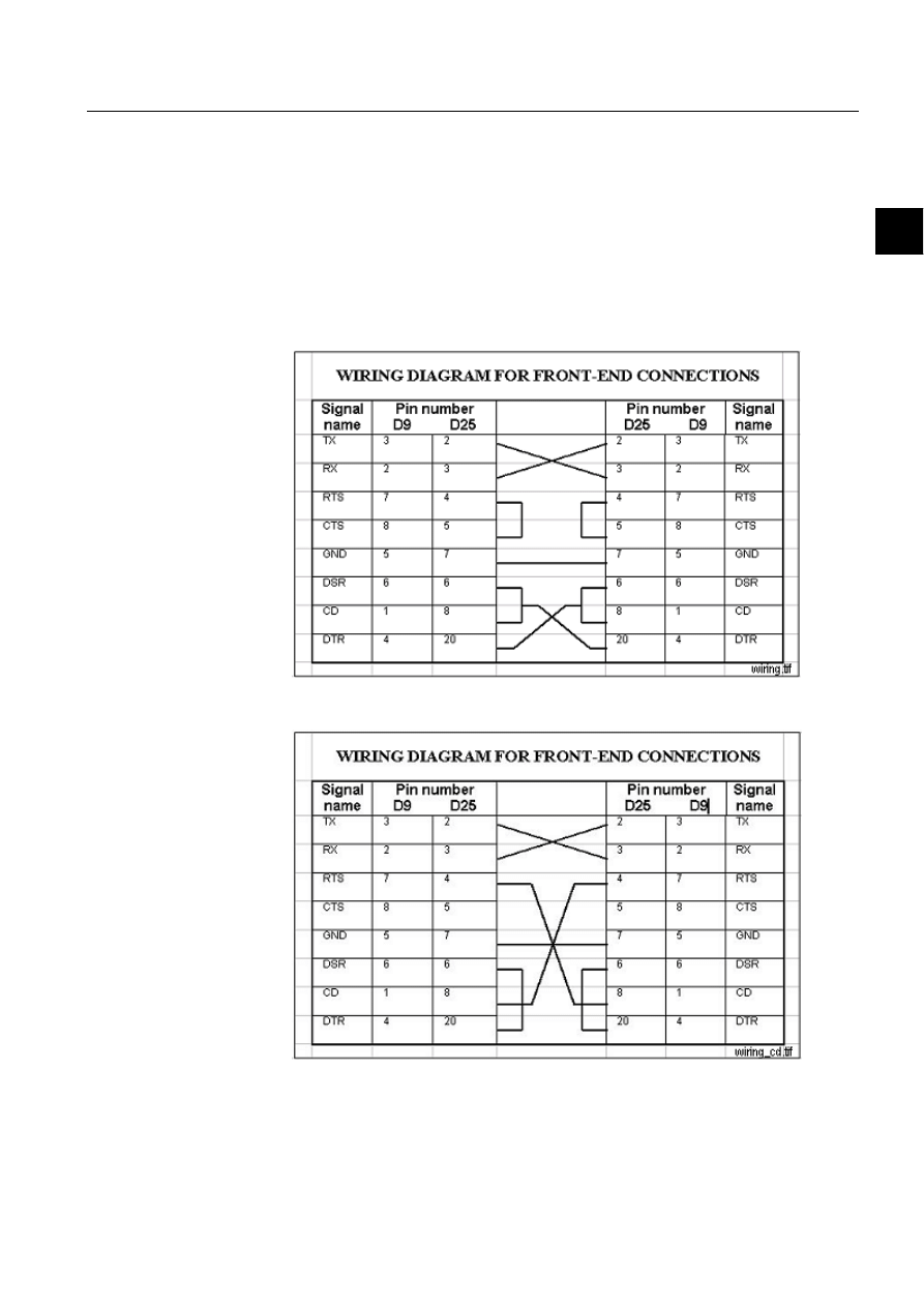
When connecting the DNP slave to a MicroSCADA DNP master using a direct
serial cable, the wiring illustrated by Figure 3.5.-1 or Figure 3.5.-2 should be used
depending on whether collision detection is used (the LK attribute of the line is 14)
or not (the LK attribute of the line is 15).
When connecting several slaves and masters to one line when collision detection is
used, a more sophisticated connection is needed. The connections should be made
in a way that when the Request to Send signal of any master or slave is set as an
indication that the station is transmitting, the Carrier Detect signal of all stations
should be set.
)LJ 6HULDOFDEOHZLULQJGLDJUDPZKHQFROOLVLRQGHWHFWLRQLVQRWXVHG
)LJ 6HULDOFDEOHZLULQJGLDJUDPZKHQFROOLVLRQGHWHFWLRQLVXVHG


1MRS751861-MEN
COM 500
35
Configuring MicroSCADA for DNP V3.00
Slave Protocol
Configuration Guide
4. Technical description
4
4. Technical
description
4.1.
General
4.1.1.
DNP V3.00 protocol
The Distribute Networks Protocol (DNP) V3.00 is a standards-based
communication protocol designed for electric utility, water, oil & gas and security
systems. DNP is hardware-independent and works with a variety of networks
enabling communication between substation computers, Remote Terminal Units
(RTUs), Intelligent Electronic Devices (IEDs) and master stations over serial or
LAN-based systems.
DNP is designed according to the Enhanced Protocol Architecture (EPA) and it
specifies the following Open Systems Interconnection (OSI) layers:
• Physical layer
• Data link layer
• Transport layer
• Application layer
The DNP transport layer is actually a pseudo-transparent layer that provides
minimum message assembly and disassembly. The purpose of the transport layer is
to provide support for application messages larger than the frame length of the data
link.
The physical layer can be any bit-serial physical layer, e.g. RS-232 C, RS-485 or
fibre transceiver. In MicroSCADA the communication takes place using the serial
port(s) of the base system computer. The interface used is RS-232 C.
A lot of the functionality of the protocol shall be implemented in SCIL by using the
application and system objects as presented in this document. The reason for this is
flexibility and versatility. Although different DNP masters are implemented
according to the same standard, functionality and requirements still vary from one
system and application to another. When some of the central parts of message
handling are implemented in SCIL, changes can easily be made, even on-line.
4.1.2.
Level of implementation
DNP V3.00 has three subset levels from 1 to 3 which each include a specific subset
of DNP message types and functionality. In MicroSCADA the DNP V3.00 protocol
has been implemented according to the Subset Level 2 of the protocol (DNP 3.00–
L2) as presented in the Table 4.1.2-1.
1MRS751861-MEN

36
1MRS751861-MEN
Configuring MicroSCADA for DNP V3.00
Slave Protocol
COM 500
4. Technical description
Configuration Guide
Table 4.1.2-1
Data object types and variations supported by MicroSCADA
Object
Request
Response
Obj.
Var.
Description
Func.
Qual.
Func.
Qual.
1
0
Binary input, all variations
1
6
1
1
Binary input
129,130
0,1
1
2
Binary input with status
129,130
0,1
2
0
Binary input change, all variations
1
6,7,8
2
1
Binary input change without time
1
6,7,8
129,130
17,28
2
2
Binary input change with time
1
6,7,8
129,130
17,28
2
3
Binary input change with relative time
1
6,7,8
129,130
17,28
10
0
Binary output, all variations
1
6
10
1
Binary output
10
2
Binary output status
129,130
0,1
12
1
Control relay output block
3,4,5,6
17,28
129
echo
20
0
Binary counter, all variations
1,7,8,9,10
17,28
20
1
32-bit binary counter
129,130
0,1
20
2
16-bit binary counter
129,130
0,1
20
3
32-bit delta counter
129,130
0,1
20
4
16-bit delta counter
129,130
0,1
20
5
32-bit binary counter without flag
129,130
0,1
20
6
16-bit binary counter without flag
129,130
0,1
20
7
32-bit delta counter without flag
129,130
0,1
20
8
16-bit delta counter without flag
129,130
0,1
21
0
Frozen counter, all variations
1
6
21
1
32-bit frozen counter
129,130
0,1
21
2
16-bit frozen counter
129,130
0,1
21
9
32-bit frozen counter without flag
129,130
0,1
21
10
16-bit frozen counter without flag
129,130
0,1
22
0
Counter change event, all variations
1
6,7,8
22
1
32-bit counter change event without time
129,130
17,28
22
2
16-bit counter change event without time
129,130
17,28
30
0
Analog input, all variations
1
6
30
1
32-bit analog input
129,130
0,1
30
2
16-bit analog input
129,130
0,1
30
3
32-bit analog input without flag
129,130
0,1
30
4
16-bit analog input without flag
1
0,1,6
129,130
0,1
32
0
Analog change event, all variations
1
6,7,8
32
1
32-bit analog change event without time
129,130
17,28
32
2
16-bit analog change event without time
129,130
17,28
40
0
Analog output status, all variations
1
6
129,130
0,1
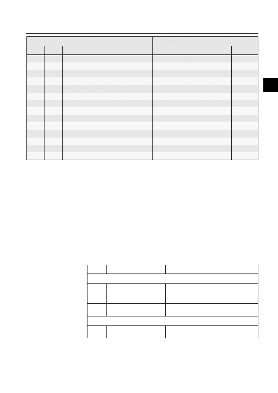
1MRS751861-MEN
COM 500
37
Configuring MicroSCADA for DNP V3.00
Slave Protocol
Configuration Guide
4. Technical description
4
Explanations:
• Obj. is the data object type.
• Var. is the variation.
• Func. is the function code of the message.
• Qual. is the qualifier code of the message in hexadecimal.
• Echo means that the response is the request mirrored.
Exceptions to the definition of the DNP V3.00 subset level 2 are indicated with bold
numbers in the table.
Each DNP V3.00 message contains a function code that describes the purpose of
the message. The function codes presented in Table 4.1.2-2 are supported by
MicroSCADA.
Table 4.1.2-2
Function code describes the purpose of the message
40
2
16-bit analog output status
41
2
16-bit analog output block
3,4,5,6
17,28
129
echo
50
1
Time and date
2
7
51
1
Time and date CTO
129,130
7
51
2
Unsynchronised time and date CTO
129,130
7
52
1
Time and date coarse
129
7
52
2
Time delay fine
129
7
60
1
Class 0 data
1
6
60
2
Class 1 data
1
6,7,8
60
3
Class 2 data
1
6,7,8
60
4
Class 2 data
1
6,7,8
80
1
Internal indications
2
0
No object
13
No object
23
Object
Request
Response
Obj.
Var.
Description
Func.
Qual.
Func.
Qual.
Code
Function
Description
Transfer Function Codes
0
Confirm
Message Fragment confirmation. No response.
1
Read
Request objects from outstation.
Respond with requested objects.
2
Write
Store specified objects to outstation.
Respond with status of operation.
Control Function Codes
3
Select
Select the output point of outstation.
Respond with status of control point.

38
1MRS751861-MEN
Configuring MicroSCADA for DNP V3.00
Slave Protocol
COM 500
4. Technical description
Configuration Guide
For more details about the implementation of DNP V3.00 protocol in
MicroSCADA, see the device profile in the end of this document.
4.1.3.
Supported process object types
Since in the DNP V3.00 slave protocol input data is sent to the master by using
SCIL statements, there is no strict relation between the MicroSCADA process
object types and DNP data object types, but the following relation presented in the
Table 4.1.3-1 can be made.
Table 4.1.3-1
Relation between the MicroSCADA process object types and
DNP data object types
4
Operate
Set the output that has previously been selected
Respond with status of control point.
5
Direct operate
Set the output directly.
Respond with status of control point.
6
Direct operate, no ack
Set the output directly.
No response.
Freeze Function Codes
7
Immediate Freeze
Copy the specified objects to freeze buffer.
Respond with status of operation.
8
Immediate Freeze, no ack
Copy the specified objects to freeze buffer.
No response.
9
Freeze and Clear
Copy the specified objects to freeze buffer
and clear the objects.
Respond with status of operation.
10
Freeze and Clear, no ack
Copy the specified objects to freeze buffer
and clear objects.
No response.
Application Control Function Codes
13
Cold Restart
Perform the desired reset sequence.
Respond with a time object.
14
Warm Restart
Perform the desired partial reset operation.
Respond with a time object.
Time Synchronisation Function Codes
23
Delay Measurement
Perform propagation delay measurement.
Response Function Codes
t
Confirm
Message fragment confirmation.
129
Response
Response to requested message.
130
Unsolicited Message
Spontaneous message without request.
Code
Function
Description
Object
Description
Process Object Type
1
Binary input
Binary input, double binary indication
10
Binary output status
Binary output
12
Control relay output block
Binary input

1MRS751861-MEN
COM 500
39
Configuring MicroSCADA for DNP V3.00
Slave Protocol
Configuration Guide
4. Technical description
4
Frozen binary counters are handled internally by the NET unit after the
corresponding freeze command has been received.
4.2.
Communication
This section gives a more detailed description of the implementation of the DNP
V3.00 slave protocol in MicroSCADA, describing also the attributes that can be
used for device communication. Examples of how to exchange data between the
master and the slave using the SCIL programming language are also given in this
section along with information of the DNP status codes.
4.2.1.
Protocol converter
Each DNP slave station configured on a line of a NET unit acts as a protocol
converter between the DNP V3.00 protocol and a base system. An internal protocol
of MicroSCADA is used in communication between the MicroSCADA nodes, for
example, between a base system and a NET unit.
In DNP there are basically two kinds of data: static data and event data. Static data
in DNP is called class 0 data. Event data can have three different classes or priorities:
1 (high priority), 2 (medium priority) and 3 (low priority). In DNP terminology static
data objects are called by their data type, e.g. “binary input” and “analog input”.
Corresponding events are called by adding “change” to the static data object, e.g.
“binary input change” and “analog change”.
Data, both static and event data can be sent from the slave to the master in two ways:
either the master polls it cyclically or when needed, or it is sent to the master
spontaneously as unsolicited messages. A combination of these two ways is also
possible. From this point of view DNP V3.00 implements both the balanced and
unbalanced transmission procedures.
Each DNP slave station has a database in the NET unit. This database contains a
static storage for the static data, and three queues for the event data, one for each
class. When data is sent from the slave to the master, the message is written to the
NET database by using the SD attribute (static data) or the EV attribute (event data).
These attributes are described later in this document. When data is sent from the
master to the slave, it is forwarded directly to the MicroSCADA process database
without going through the NET database.
20
Binary counter
Pulse counter
30
Analog input
Analog input
40
Analog output status
Analog output
41
Analog output block
Analog input
Object
Description
Process Object Type

40
1MRS751861-MEN
Configuring MicroSCADA for DNP V3.00
Slave Protocol
COM 500
4. Technical description
Configuration Guide
4.2.2.
Communication modes
A communication mode describes how messages are sent between the DNP V3.00
slave and the master by polling or by means of unsolicited messages, or by both
methods. The following four cases can be identified:
• Quiescent Operation. In this mode the master does not poll the slave, all the
communication is based on unsolicited (i.e. spontaneous) report-by-exception
messages. The master can send application layer confirmations to the slave.
• Unsolicited Report-by-Exception Operation. The communication is basically
unsolicited but the master occasionally sends integrity polls for Class 0 data to
verify that its database is up-to-date.
• Polled Report-by-Exception Operation. The master frequently polls for event
data and occasionally for Class 0 data.
• Static Report-by-Exception Operation. The master polls only for Class 0 data or
the specific data it requires.
When configuring DNP V3.00 stations in MicroSCADA, the communication mode
is set when the NET database is initialised by using the SD attribute. The
communication mode must be select to match the behaviour of the master. The most
important issue is that whether or not the master accepts unsolicited messages.
4.2.3.
Handshaking
By default, NET sends spontaneous “test function of link” messages to the DNP line
in order to check that the communication link is open. The message is sent at
intervals specified by the PD attribute of the line. If the DNP master does not
acknowledge this message, the communication will not be established.
If the DNP master does not accept spontaneous “test function of link” messages
from the slave, the sending of these messages can be prevented by setting both the
PD and LA attributes of the line to zero. In this case the communication link is not
supervised cyclically.
4.2.4. DNP3.0
in
LAN/WAN
The DNP3.0/LAN protocol is used in LAN and WAN networks to connect central
stations and outstations to each other. Since the stations use an open TCP/IP
interface as a connection to the network, the structure and the characteristics of the
network used will be invisible to the application. The transferred data messages are
equal to the ones used in the serial line based on the DNP 3.0 protocol. When
operating as a DNP slave, MicroSCADA is the server-end of the connection.
When operating as a controlled station (slave), only one connection to the
controlling station may be open at the same time. Each connection has a
configurable and unique IP address. There may be only one DNP slave line
operating in the TCP or UDP mode in the same computer.
The connection type is defined with line attribute SD. The client internet address is
defined with station attribute IA. Configuration examples for LAN connection are
given in the Appendix. Configuration examples .

1MRS751861-MEN
COM 500
41
Configuring MicroSCADA for DNP V3.00
Slave Protocol
Configuration Guide
4. Technical description
4
4.2.5.
Addressing
In the DNP V3.00 protocol each link layer message has two addresses: SOURCE
address indicates from which station the message is coming and DESTINATION
address tells which station the message is going to. When configuring a DNP slave
station in MicroSCADA, the SA (Slave Address) attribute should be equal to the
SOURCE address and the MA (Master Address) equal to the DESTINATION
address.
In DNP terminology a data point address is called index. Several data points of the
different data object type, e.g. binary input and analog input, can have the same
index. An individual data point is thus identified with the combination of data object
type and index.
4.2.6.
Internal indications
Each response message sent by the slave contains a two-octet field called internal
indications, which indicates the current state of the slave device. This information
can be used for monitoring the state of the slave or for troubleshooting purposes.
The internal indications sent by the DNP slave can be read by using the IN attribute
of the DNP master station. The bits of the internal indications are as presented in
Table 4.2.6-1.
Table 4.2.6-1
Bits of the internal indications
For example, if the value of the IN attribute is 144 = 0000000010010000, it means
that the slave should be synchronised (octet 1, bit 4) by the master and the slave has
restarted (octet 1, bit 7).
Octet
Bit
Description
1
0
All stations message received
1
1
Class 1 data available
1
2
Class 2 data available
1
3
Class 3 data available
1
4
Time-synchronisation required from the master
1
5
Some or all of the Outstation’s digital output points are in local state
1
6
Device trouble
1
7
Device restart
2
0
Function code not implemented
2
1
Requested object(s) unknown
2
2
Parameters in the qualifier, range or data fields are not valid or out of
range
2
3
Event buffer(s), or other application buffers overflow
2
4
Request understood but requested operation is already executing
2
5
Current configuration in the slave is corrupt
2
6
Currently always returned as zero (0)
2
7
Currently always returned as zero (0.
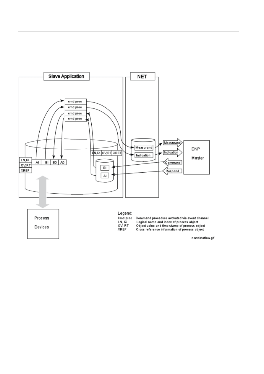
42
1MRS751861-MEN
Configuring MicroSCADA for DNP V3.00
Slave Protocol
COM 500
4. Technical description
Configuration Guide
4.2.7.
Data flow
Figure 4.2.7.-1 describes the data flow between the process devices and the DNP
master. Both directions are described separately since the data is handled in a
different way depending on the direction.
)LJ
'DWDIORZEHWZHHQWKHSURFHVVGHYLFHVDQGWKH'13PDVWHU
Input data
When input data, for example, indications and measured values are sent from the
process devices to the DNP master, the following steps are taken:
The process devices send data to the MicroSCADA process database.
The updated process object activates an event channel.
The event channel executes a command procedure. Some of the attributes of the
process object are given as arguments to the command procedure.

1MRS751861-MEN
COM 500
43
Configuring MicroSCADA for DNP V3.00
Slave Protocol
Configuration Guide
4. Technical description
4
The command procedure sends the data to the NET database by using the SD
and EV attributes based on specific cross-reference information.
The NET unit sends data to the DNP master either as static or unsolicited data.
The cross-reference information is the data needed to deliver the data to the NET
database for example object address and message type. The number event channels
and command procedures needed to deliver data to the master depends on the
application, one solution is to have one command procedure for each process object
type. Examples of the command procedures are given later in this document.
!
In the quiescent operation mode static data is sent to the master as unsolicited
messages only at start-up and when the status of a data point changes. Besides these
situations, data must be sent as change events or by means of polling.
Output data
When output data, for example, object commands and analog setpoints are sent
from the DNP master to the process devices, the following steps are taken:
The command is received by the MicroSCADA process database. There must
be a separate input process object for each DNP command address. This part of
the process object is created manually when the signal engineering is done.
The updated process object activates an event channel.
The event channel executes a command procedure. Some of the attributes of the
process object are given as arguments to the command procedure.
The command procedure sends the process devices by setting the corresponding
output process object(s) and, if required, sends a confirmation to the DNP
master via the NET unit.
Cross-reference data can also be used with commands. It can contain, for example,
information of the logical names and indices of the output process objects. Examples
of the command procedures are given later in this document.
Other messages
In addition to the input and output data described above there are also some other
messages transferred between the master and the slave. These messages contain, for
example, synchronisation commands and restart commands. Some of these
commands are handled automatically by the NET unit while others require SCIL
programming. The ones that require SCIL programming are described in detail later
in this document.
System and application commands and DNP messages that are not recognised by the
slave station are forwarded to a bit stream process object with an address as defined
by the CA address of the slave station. By using this process object the messages can
be interpreted and processed by SCIL, if necessary.

44
1MRS751861-MEN
Configuring MicroSCADA for DNP V3.00
Slave Protocol
COM 500
4. Technical description
Configuration Guide
4.2.8.
Device communication attributes
6'
6SRQWDQHRXV'DWD
Writing data to the SD attribute updates the corresponding static data object (class
0) of the NET database. It does not create an event even if the value changes; events
must be generated by using the EV attribute. The second purpose of the SD attribute
is to construct the NET database. When a data object is updated while the DI
attribute is 0, the object is added to the database if it is not previously known. There
must be a data object for each input DNP address.
Data type:
Vector
Value:
See above
Index range:
0...3, see above
Access: No
limitations
,QGH[LQJ
While writing:
0…3. The index determines which class is used as the default
class, when an unsolicited message is created for this address
using the EV attribute as follows:
0: the event generation is disabled for this object
1: default class is 1
2: default class is 2
3: default class is 3
While reading:
(TYPECODE..IOA+ TYPECODE)
'HVFULSWLRQRIWKHYHFWRUSDUDPHWHUV
TYPECODE:
A code for the data object type as presented in Table 4.2.8-1.
Table 4.2.8-1
Codes for data object types
IOA:
Object address, see description below
9DOXH
When writing:
vector (OBJ, VAR, IOA, VAL, FLAG, [CTRL])
When reading:
vector (EV_CLASS, TYPE, VAR, IOA, VAL, FLAG, CTRL)
'HVFULSWLRQRIWKHYHFWRUSDUDPHWHUV
OBJ:
Data object type
VAR:
Object variation, depends on the data object type
Code
Description
0
Binary Input
1
Binary Output
2
Binary Counter
3
Analog Input
4
Analog Output

1MRS751861-MEN
COM 500
45
Configuring MicroSCADA for DNP V3.00
Slave Protocol
Configuration Guide
4. Technical description
4
In DNP V3.00 message types are identified with the combination of data object type
and variation. One data object has usually several variations, for example, binary
input without status (data object 1, variation 1) and binary input with status (data
object 1, variation 2).
When the static data object in the NET database is updated, the parameters OBJ and
VAR define the default variation used in responses to the master, i.e. the variation
used if no variation is specified in the request from the master. Data object types and
variations presented in Table 4.2.8-2 are possible.
Table 4.2.8-2
Message types are identified with the combination of data
object type and variation
IOA:
Object address.
Value:
0...255
when IL attribute = 1
0…65535,
when IL attribute = 2
VAL:
The value of the object. The value range depends on the data
object type. See the examples later in this document. If the object
is of binary type the values 10…13 are converted to double
indications as follows: 10 -> 0, 11 -> 1, 12 -> 2, 13 -> 3.
FLAG:
Integer, bit mask of the status bits of object. Status bits indicate
the current state of the data object. The bits in the flag byte are
different for different data object types (see the examples later in
this document). The relation between the DNP status bits and
process object attributes is as shown in Table 4.2.8-3.
Table 4.2.8-3
Status bits indicate the current state of the data object
Object
Description
Variations
1
Binary Input
1, 2
10
Binary Output
2
20
Binary Counter
1, 2, 3 4, 5, 6, 7, 8
30
Analog Input
1, 2, 3, 4
40
Analog Output
2
Bit
Description
Attr
On-line
The on-line bit indicates that the binary input point has been
read successfully. If this field is set to off-line, the state of
the digital point may not be correct.
OS
Restart
The restart bit indicates that the field device which
originated the data object is currently restarting. This can
be the device reporting this data object.
-
Communication
lost
The communication lost bit indicates that the device
reporting this data object has lost communication with the
originator of the data object.
OS
Remote forced
data
The remote forced data bit indicates that the state of the
binary input has been forced to its current state at a device
other than the end device.
-

46
1MRS751861-MEN
Configuring MicroSCADA for DNP V3.00
Slave Protocol
COM 500
4. Technical description
Configuration Guide
CTRL:
Integer, a bit mask of the control bits of the data object. The control bits
define in which conditions the data object is reported to the master, i.e.
sent as a response to a request. The control bits also define whether an
unsolicited message is generated or not. The data bits are as follows:
Bit 0:
0 = object is not reported to the master at all
1 = object is reported to the master
Bit 1:
0 = unsolicited messages of this object are not generated
1 = object is reported as an unsolicited message
Bit 2:
0 = the static object is not sent as an unsolicited message
1 = the static object is sent as an unsolicited message at start up and
when the status of the object changes
CTRL is optional when the value of the DI attribute of the station is 1. For the
different communication modes the value of CTRL can be, for example, as
presented in Table 4.2.8-4.
Table 4.2.8-4
The different communication modes and corresponding
control bits
(9
(YHQW'DWDZLWK7LPH6WDPS
By setting the EV attribute the user can send time-tagged events to the DNP master.
An event is generated if:
• The value of the data object changes. In case of an analog data object, the change
must be greater than the DELTA parameter.
• The status (FLAG parameter) of the data object changes.
The EV attribute updates also the static data object in the NET database. Whether an
unsolicited message is generated depends on the value of the CTRL element used
Local forced data
The local forced data bit indicates that the state of the
binary input has been forced to its current state at the end
device.
SB
Chatter filter
The chatter filter bit indicates that the binary input point has
been filtered in order to remove unneeded transitions in the
state of the point.
BL
Roll-over
When set, the roll-over bit indicates that the accumulated
value has exceeded the last reported recordable. The
counter value has been reset to 0 upon the roll-over and
counting has resumed as normal. This bit is cleared when
the counter value (plus the roll-over state) is reported.
-
Over range
The out of range field indicates that the digitised signal or
calculation has exceeded the value range.
OR
Bit
Description
Attr
Communication Mode
CTRL
Quiescent Operation
7
Unsolicited Report-by-Exception Operation
3
Polled Report-by-Exception Operation
1
Polled Static Operation
1

1MRS751861-MEN
COM 500
47
Configuring MicroSCADA for DNP V3.00
Slave Protocol
Configuration Guide
4. Technical description
4
when the data point was initialised by using the SD attribute. By reading the EV
attribute the user can enquire the number of items in the event queues.
Data type:
Vector
Value:
See above
Index range:
0...3, see above
Access: No
limitations
,QGH[LQJ
0...3:
The unsolicited message class as follows:
0 or not given:
The default class determined with the SD attribute is used
1...3:
Class 1, 2 or 3
9DOXH
When writing:
Vector (TYPE, VAR, IOA,VAL, FLAG, DELTA, RT, RM,
[ALL])
When reading:
Integer, the length of the queue of the unsolicited message class
'HVFULSWLRQRIWKHYHFWRUSDUDPHWHUV
OBJ:
Data object type, integer
VAR:
Object variation, depends on the data object type, integer
In DNP V3.00 message types are identified with the combination of data object type
and variation. One data object has usually several variations, for example, binary
input change without time (data object 2, variation 1) and binary input change with
time (data object 2, variation 2).
The following data object types and variations showed in Table 4.2.8-5 are
possible.
Table 4.2.8-5
The message types are identified with the combination of data
object type and variation
IOA:
Object address, integer
Value:
0...255
, when IL attribute = 1
0...65535
, when IL attribute = 2
VAL:
The value of the object. The value range depends on the data
object type. See the examples later in this document.
FLAG:
Integer, bit mask of the status bits of object. Status bits indicate
the current state of the data object. The bits in the flag byte are
different for different data object types. See the examples later in
this document.
DELTA:
Integer. An event is generated only if the change of value is
greater than the delta value. This parameter can be used to
establish a deadband handling in the NET database.
Object
Description
Variations
2
Binary Input Change
1,2,3
22
Binary Counter Change Event
1,2,3,4
32
Analog Change Event
1,2,3,4

48
1MRS751861-MEN
Configuring MicroSCADA for DNP V3.00
Slave Protocol
COM 500
4. Technical description
Configuration Guide
RT:
Registration time. The registration time included in the time
stamp of the unsolicited message.
RM:
Registration milliseconds, integer 0..999. The millisecond part
of the time stamp of the unsolicited message.
ALL
If ALL is not zero, an event is always generated, even if the value
does not change.
&)
&RPPDQG&RQILUPDWLRQ
The CF attribute is used to accept commands received by the NET unit. The NET
unit does not send a response message to the command before the command is
confirmed using the CF attribute. The NET automatically stores the received
commands to a table. When the parameter ADDR is given when writing data to the
CF attribute, the confirmed command is searched (latest first) from the table. If no
command with matching address is found, the error 13925 =
DNPC_NO_ACTIVE_COMMAND is returned and a response message is not sent.
Data type:
Vector
Value:
Vector (CS, OBJ_ADDR)
Access:
Write-only
'HVFULSWLRQRIWKHYHFWRUSDUDPHWHUV
CS:
Control status, integer 0.255. Control status indicates the status
of the command to the master.
Valid status codes:
0:
Request accepted or initiated
1:
Request not accepted, the time between select and operate was too long
2:
No previous select message
3:
Request not accepted because of a formatting error
4:
Control operation is not supported for this point
5:
Request not accepted because the point is already active
6:
Request not accepted because of control hardware problems
7 ... 127:
Undefined
By adding 128 to the values above, the slave will report that some of the binary
outputs are in local state.
OBJ_ADDR:
Object address of the confirmed command, integer. In most
cases this is the address of the process object receiving the
command.
Value:
0...255,
when IL attribute = 1
0...65535,
when IL attribute = 2
',
'DWDEDVH,QLWLDOLVHG
When this attribute is set to 0, the NET database can be initialised by using the SD
attribute. When the value of this attribute is returned to 1 after the initialisation, the
communication between the master and the slave can be started. When this attribute
is set to 2, the NET database is cleared and it can be initialised by using the SD
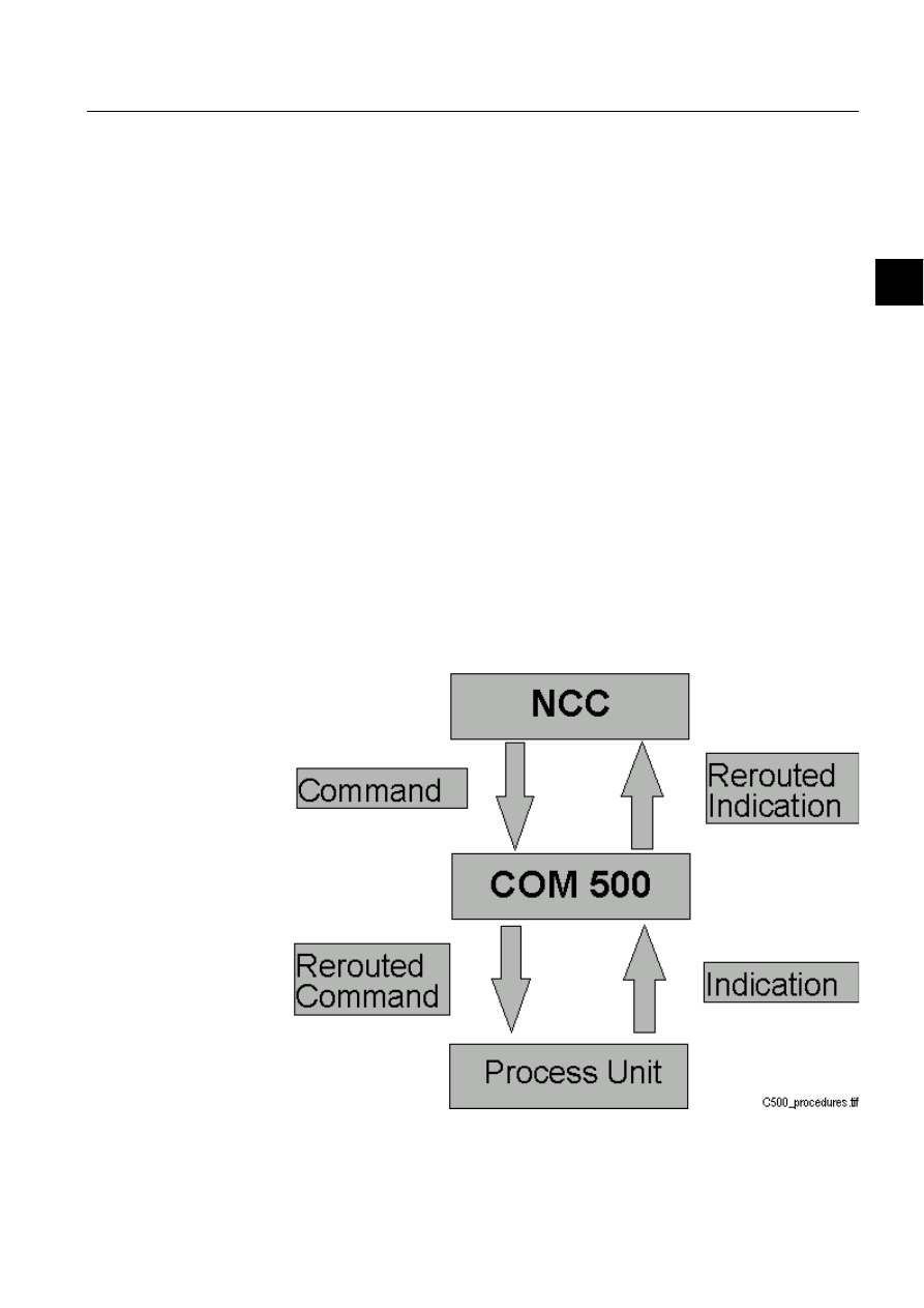
1MRS751861-MEN
COM 500
49
Configuring MicroSCADA for DNP V3.00
Slave Protocol
Configuration Guide
4. Technical description
4
attribute. While DI = 0, the slave does not send data as response to requests from the
master.
Data type:
Integer
Value:
0, 1 or 2
Access:
No limitations
56
5HVHW(YHQW4XHXHV
The RS attribute can be used for clearing the content of one or several event queues.
Data type:
Integer
Value:
0...3
0 = reset all queues
1 = reset the class 1 queue
2 = reset the class 2 queue
3 = reset the class 3 queue
Access:
Write-only
4.3.
Command procedures
4.3.1.
Command procedures in COM 500
Signals are sent from the process units to a NCC and commands from a NCC to the
process unit. COM 500 reroutes the signals using command procedures and cross-
references (see Figure 4.3.1.-1). The command procedures, which are used for signal
rerouting, are described here.
)LJ
&20UHURXWHVWKHVLJQDOV

50
1MRS751861-MEN
Configuring MicroSCADA for DNP V3.00
Slave Protocol
COM 500
4. Technical description
Configuration Guide
If the DNP V3.00 slave protocol is used with COM 500, the command procedures
available for COM 500 are used. The cross-reference information is entered in the
Signal Cross-reference tool. In order to receive more information, refer to COM 500
Engineering Manual. Table 4.3.1-1 shows the used COM 500 command procedures
and event channels.
Table 4.3.1-1
Used event channels and command procedures
* = Used for reporting the status of the output object to the master.
4.3.2.
Command procedures in SYS 500
4.3.2.1.
Command procedures for process data
The command procedures presented in this chapter cannot cover all combinations
and requirements but they provide examples of the implementation.
The connection between the MicroSCADA process objects and messages to and
from the DNP master is made by using cross-reference data. Cross-reference data is
written to the FX (Free teXt) attribute of the process objects by using the Process
Object Definition Tool.
Cross-references for data transfer from MicroSCADA to the DNP master are kept
in the FX attribute, which is a string of max 30 characters (10 before revision
8.4.2). The general syntax for a DNP cross-reference is:
<STA_NUMBER><ADDRESS><ST_TYPE><ST_VAR><DEF_CLASS>
[<EV_TYPE>][<EV_VAR>][<EV_CLASS>][<EV_DELTA>]
STA_NUMBER: Logical STA number (range 1...255). The value is stored as 3
ASCII digits with leading spaces added if necessary. FX string
positions 1...3 are used for this value.
ADDRESS:
The address in the database of the DNP master. Stored as 5
ASCII digits with leading spaces added if necessary. Address
uses FX string positions 4 ... 8.
ST_TYPE:
The data object type of the static data object in the NET
database. Stored as 2 ASCII digits with leading spaces added if
necessary. Static data object type uses FX string positions 9...10.
ST_VAR:
The data object type of the static data object in the NET
database. Stored as 2 ASCII digits with leading spaces added if
necessary. Static variation uses FX string positions 11...12.
Process Object Type
Event Channel
Command Procedure
Analog Input
COM_USAI
COM_USAI
Single Indication
COM_USDI
COM_USDI
Double Indication
COM_USDB
COM_USDB
Pulse Counter
COM_USPC
COM_USPC
Binary Outputs
COM_DSBO
COM_USBO*
COM_DSBO
COM_USBO*
Analog Outputs
COM_DSAO
COM_USAO*
COM_DSAO
COM_USAO*

1MRS751861-MEN
COM 500
51
Configuring MicroSCADA for DNP V3.00
Slave Protocol
Configuration Guide
4. Technical description
4
DEF_CLASS:
The default class used when a change of the process object
generates an event. Must be set to 0, if no event is generated.
Stored as one ASCII digit. Static variation uses FX string
position 13.
EV_TYPE:
The data object type used when a change of the process object
generates an event. Can be omitted if no event is generated.
Stored as 2 ASCII digits with leading spaces added if necessary.
Event data object type uses FX string positions 14...15.
EV_VAR:
The variation used when a change of the process object generates
an event. Stored as 2 ASCII digits with leading spaces added if
necessary. Event variation uses FX string positions 16...17.
EV_CLASS:
The event class used when a change of the process object
generates an event. If set to 0, the default class is used. Stored as
one ASCII digit. Event variation uses FX string position 18.
EV_DELTA:
The delta value used when an analog event is generated. The
change of the value must be greater than the delta value in order
to generate an event. Stored as 12 ASCII digits with leading
spaces added if necessary. Event delta uses FX string positions
19...30.
The used STA object attribute depends on whether an event is generated (EV) or not
(SD). The value of the FLAG parameter is calculated from the attributes of the
process object.
An example of the cross-reference of a binary input signal:
Another example of the cross-reference of an analog input signal, which does not
generate an event:
!
The NET database initialisation is described in a separate example. Thus, the CTRL
parameter is omitted in the following examples when updating the static data object
in the NET database by using the SD attribute.
Analog inputs
If a 16-bit variation is used, analog values must be limited or scaled to the Value –
32768...32767. This can be done in SCIL or by using a specific scale object and the
SCALE function.
FX
1
7 5 0 0
1
2 1
2
3 0
0
CHAR
1 2 3 4 5 6 7 8 9 0 1 2 3 4 5 6 7 8 9 0 1 2 3 4 5 6 7 8 9 0
FX
1
5 2 3 0 3 0
2 0
CHAR
1 2 3 4 5 6 7 8 9 0 1 2 3 4 5 6 7 8 9 0 1 2 3 4 5 6 7 8 9 0

52
1MRS751861-MEN
Configuring MicroSCADA for DNP V3.00
Slave Protocol
COM 500
4. Technical description
Configuration Guide
All the analog values are connected to the same event channel/command procedure
combination. The command procedure is activated each time the process object is
updated. It reads the updated value, and if necessary, limits or scales it and sends it
to NET by using the cross-reference data. An example of the command procedure
is listed below:
;read cross-reference data
;common data
@FX = ’LN’:PFX’IX’
@STA_NR = DEC_SCAN(SUBSTR(%FX,1,3))
@ADDR = DEC_SCAN(SUBSTR(%FX,4,5))
@ST_TYPE = DEC_SCAN(SUBSTR(%FX,9,2))
@ST_VAR = DEC_SCAN(SUBSTR(%FX,11,2))
@DEF_CLASS = DEC_SCAN(SUBSTR(%FX,13,1))
;data for unsolicited messages
#IF %DEF_CLASS <> 0 #THEN #BLOCK
@UN_TYPE = DEC_SCAN(SUBSTR(%FX,14,2))
@UN_VAR = DEC_SCAN(SUBSTR(%FX,16,2))
@UN_CLASS = DEC_SCAN(SUBSTR(%FX,18,1))
@UN_DELTA = DEC_SCAN(SUBSTR(%FX,19,0))
#BLOCK_END
;if 16-bit value (even variation), limit value to U16
#IF (EVEN(%ST_VAR) OR EVEN(%ST_VAR)) AND ABS(%OV) > 32767 - #THEN #BLOCK
@VALUE = ROUND(MIN(MAX(-32767,%OV),32767)
@OR = 1
#BLOCK_END
#ELSE @VALUE = ROUND(%OV)
;compose the flag byte
#IF %OS == 2 #THEN @COMM_LOST = 1
#ELSE @COMM_LOST = 0
#IF %OS == 1 OR %OS == 10 #THEN @ON_LINE = 0
#ELSE @ON_LINE = 1
@FLAG = %ON_LINE+%COMM_LOST*4+%SB*16+%OR*32
;send data to NET
#IF %DEF_CLASS == 0 #THEN – ;static data
#SET STA’STA_NR’:SSD(%DEF_CLASS)=(%ST_TYPE,%ST_VAR,%ADDR,-%VALUE,%FLAG)
#ELSE - ;event
#SET STA’STA_NR’:SEV(%UN_CLASS)=(%UN_TYPE,%UN_VAR,%ADDR,-
%VALUE,%FLAG,%UN_DELTA,%RT,%RM,0)
Single indications
All the binary inputs are connected to an event channel/command procedure
combination that sends the process value to the NET unit. The command procedure
is activated each time the process object is updated. It reads the updated value and
sends it to NET by using cross-reference data. An example of the command
procedure is listed below:
;read cross-reference data
;common data
@FX = 'LN':PFX'IX'
@STA_NR = DEC_SCAN(SUBSTR(%FX,1,3))
@ADDR = DEC_SCAN(SUBSTR(%FX,4,5))
@ST_TYPE = DEC_SCAN(SUBSTR(%FX,9,2))
@ST_VAR = DEC_SCAN(SUBSTR(%FX,11,2))
@DEF_CLASS = DEC_SCAN(SUBSTR(%FX,13,1))
;data for unsolicited messages
#IF %DEF_CLASS <> 0 #THEN #BLOCK
@UN_TYPE = DEC_SCAN(SUBSTR(%FX,14,2))
@UN_VAR = DEC_SCAN(SUBSTR(%FX,16,2))
@UN_CLASS = DEC_SCAN(SUBSTR(%FX,18,1))

1MRS751861-MEN
COM 500
53
Configuring MicroSCADA for DNP V3.00
Slave Protocol
Configuration Guide
4. Technical description
4
@UN_DELTA = DEC_SCAN(SUBSTR(%FX,19,0))
#BLOCK_END
;compose the flag byte
#IF %OS == 2 #THEN @COMM_LOST = 1
#ELSE @COMM_LOST = 0
#IF %OS == 1 OR %OS == 10 #THEN @ON_LINE = 0
#ELSE @ON_LINE = 1
@FLAG = %ON_LINE+%COMM_LOST*4+%SB*16+%BL*32
;send data to NET
#IF %DEF_CLASS == 0 #THEN – ;static data
#SET STA’STA_NR’:SSD(%DEF_CLASS)=(%ST_TYPE,%ST_VAR,%ADDR,-ROUND(%OV),%FLAG)
#ELSE - ;event
#SET STA’STA_NR’:SEV(%UN_CLASS)=(%UN_TYPE,%UN_VAR,%ADDR,-
ROUND(%OV),%FLAG,%UN_DELTA,%RT,%RM,0)
Double indications
Double indications are not supported directly in DNP V3.00. It is possible to send
two-bit indications from MicroSCADA by adding 10 to the corresponding binary
input value as follows: 10 -> 0, 11 -> 1, 12 -> 2, 13 -> 3. This will reserve two binary
input objects with consecutive addresses from the NET database and, if an
unsolicited message is generated, generate two messages with consecutive
addresses. Other parameters than values are as described in the previous example.
All the binary inputs are connected to an event channel/command procedure
combination that sends the process value to the NET unit. The command procedure
is activated each time the process object is updated. It reads the updated value and
sends it to NET by using cross-reference data.
Pulse counters
Pulse counters are termed binary counters in DNP V3.00 protocol. Frozen counters
(counters with frozen values) are handled internally by NET and cannot be written
to NET by using SCIL. All the pulse counters are connected to an event channel /
command procedure combination that sends the process value to the NET unit. The
command procedure is activated each time the process object is updated. It reads the
updated value and sends it to NET by using cross-reference data.
;read cross-reference data
;common data
@FX = 'LN':PFX'IX'
@STA_NR = DEC_SCAN(SUBSTR(%FX,1,3))
@ADDR = DEC_SCAN(SUBSTR(%FX,4,5))
@ST_TYPE = DEC_SCAN(SUBSTR(%FX,9,2))
@ST_VAR = DEC_SCAN(SUBSTR(%FX,11,2))
@DEF_CLASS = DEC_SCAN(SUBSTR(%FX,13,1))
;data for unsolicited messages
#IF %DEF_CLASS <> 0 #THEN #BLOCK
@UN_TYPE = DEC_SCAN(SUBSTR(%FX,14,2))
@UN_VAR = DEC_SCAN(SUBSTR(%FX,16,2))
@UN_CLASS = DEC_SCAN(SUBSTR(%FX,18,1))
@UN_DELTA = DEC_SCAN(SUBSTR(%FX,19,0))
#BLOCK_END
;compose the flag byte
#IF %OS == 2 #THEN @COMM_LOST = 1
#ELSE @COMM_LOST = 0
#IF %OS == 1 OR %OS == 10 #THEN @ON_LINE = 0
#ELSE @ON_LINE = 1

54
1MRS751861-MEN
Configuring MicroSCADA for DNP V3.00
Slave Protocol
COM 500
4. Technical description
Configuration Guide
@FLAG = %ON_LINE+%COMM_LOST*2+%SB*8
;send data to NET
#IF %DEF_CLASS == 0 #THEN – ;static data
#SET STA’STA_NR’:SSD(%DEF_CLASS)=(%ST_TYPE,%ST_VAR,%ADDR,-
ROUND(%OV),%FLAG)
#ELSE - ;event
#SET STA’STA_NR’:SEV(%UN_CLASS)=(%UN_TYPE,%UN_VAR,%ADDR,-
ROUND(%OV),%FLAG,%UN_DELTA,%RT,%RM,0)
4.3.2.2.
Command procedures for the status of output objects
In DNP V3.00 protocol it is possible to report the status of the binary and analog
output objects to the master. This means that output information is sent as if it was
input data. Only static data objects are provided for the status of output objects, no
unsolicited messages are available.
When reporting the status of multiple output objects (e.g. the four binary objects of
a controllable SPA device) to the master, it is often enough to connect to one output
object. The other way is to combine the status of all the outputs by using logical
AND/OR operations.
All the output objects of the same type that are reported to the master are connected
to an event channel / command procedure combination that sends the process value
to the NET unit. The command procedure is activated each time the process object
is updated. It reads the updated value and sends it to NET by using cross-reference
data. In this case the cross-reference information related to unsolicited messages can
be left out.
;common data
@FX = 'LN':PFX'IX'
@STA_NR = DEC_SCAN(SUBSTR(%FX,1,3))
@ADDR = DEC_SCAN(SUBSTR(%FX,4,5))
@ST_TYPE = DEC_SCAN(SUBSTR(%FX,9,2))
@ST_VAR = DEC_SCAN(SUBSTR(%FX,11,2))
@DEF_CLASS = DEC_SCAN(SUBSTR(%FX,13,1))
;compose flag byte
#IF %OS == 2 #THEN @COMM_LOST = 1
#ELSE @COMM_LOST = 0
#IF %OS == 1 OR %OS == 10 #THEN @ON_LINE = 0
#ELSE @ON_LINE = 1
@FLAG = %ON_LINE+%COMM_LOST*4+%SB*16+%BL*32
;send data to NET
#SET STA’STA_NR’:SSD(%DEF_CLASS)=(%ST_TYPE,%ST_VAR,%ADDR,-
ROUND(%OV),%FLAG)
4.3.2.3.
Command procedures for initialising the NET database
All the input signals that are to be sent to the DNP master must be written to NET
while the DI attribute of the corresponding STA object is 0. This will initialise the
NET internal database by creating static data objects. The initialisation must be
made:
• At start-up. This should be done after the input process objects have been updated
to avoid unnecessary sending of bad status.
• Whenever signals are added or removed, or any of the cross-reference parameters
(address, data object type etc.) are changed.

1MRS751861-MEN
COM 500
55
Configuring MicroSCADA for DNP V3.00
Slave Protocol
Configuration Guide
4. Technical description
4
After the initialisation is completed, the DI attribute must be set to 1 to establish
communication to the master. While DI = 0 the slave does not respond with data to
the requests from the master.
Listed below is an example of a command procedure that initialises the NET
database by using the same cross-reference data as in the examples above. This
command procedure can be executed, for example, from the predefined command
procedure APL_INIT_1. When using this procedure, the value of the control byte
(CTRL) must be changed to correspond to the master.
;initialise variables
@XREF_STA_NRS = VECTOR()
;find all process objects with cross-reference data
#LOOP
@XREF_OBJECTS = APPLICATION_OBJECT_LIST(0,"IX","A","F","",-
”IU==1 AND SS>0 AND FX<>”””””,(“FX”,"OS","PT","OV","LN",-
"IX","RT","RM","BL","SB","OR"),10000)
#IF LENGTH(XREF_OBJECTS:VLN) > 0 #THEN #BLOCK
;control byte (depends on communication mode)
@CTRL = 3 ; unsolicited report-by-exception mode
;initialise static data objects in NET
#LOOP_WITH SIGNAL = 1.. LENGTH(XREF_OBJECTS:VLN)
;cross-reference data
@FX = XREF_OBJECTS:VFX(%SIGNAL)
@STA_NR = DEC_SCAN(SUBSTR(%FX,1,3))
@ADDR = DEC_SCAN(SUBSTR(%FX,4,5))
@ST_TYPE = DEC_SCAN(SUBSTR(%FX,9,2))
@ST_VAR = DEC_SCAN(SUBSTR(%FX,11,2))
@DEF_CLASS = DEC_SCAN(SUBSTR(%FX,13,1))
;set DI to zero, if not already set
#IF LENGTH(SELECT(%XREF_STA_NRS,”==%STA_NR”))== 0 –
#THEN #BLOCK
@XREF_STA_NRS = APPEND(%XREF_STA_NRS,%STA_NR)
#SET STA’STA_NR’:SDI = 0
#BLOCK_END
; substitution value and flag for each data type
@OS = XREF_OBJECTS:VOS(%SIGNAL)
@BL = XREF_OBJECTS:VBL(%SIGNAL)
@SB = XREF_OBJECTS:VSB(%SIGNAL)
#IF %OS == 2 #THEN @COMM_LOST = 1
#ELSE @COMM_LOST = 0
#IF %OS == 1 OR %OS == 10 #THEN @ON_LINE = 0
#ELSE @ON_LINE = 1
#CASE XREF_OBJECTS:VPT(%SIGNAL)
#WHEN 3 #BLOCK ; binary input
@SUBS_VALUE = 1
@FLAG = %ON_LINE+%COMM_LOST*4+%SB*16+%BL*32
#BLOCK_END
#WHEN 9 #BLOCK ;analog input
@SUBS_VALUE = 0
@FLAG = %ON_LINE+%COMM_LOST*4+%SB*16+%BL*32
#BLOCK_END
#WHEN 12 #BLOCK ;double binary input
@SUBS_VALUE = 11
@FLAG = %ON_LINE+%COMM_LOST*4+%SB*16+%BL*32
#BLOCK_END
#WHEN 13 #BLOCK ;pulse counter
@SUBS_VALUE = 0
@FLAG = %ON_LINE+%COMM_LOST*2+%SB*8
#BLOCK_END
#CASE_END
;if not sampled or error, give substitution value
#IF %OS >= 10 #THEN @VALUE = %SUBS_VALUE

56
1MRS751861-MEN
Configuring MicroSCADA for DNP V3.00
Slave Protocol
COM 500
4. Technical description
Configuration Guide
#ELSE @VALUE = XREF_OBJECTS:VOV(%SIGNAL)
#SET STA’STA_NR’:SSD(%DEF_CLASS)= -
(%ST_TYPE,%ST_VAR,%ADDR,%VALUE,%FLAG,%CTRL)
#LOOP_END
#BLOCK_END
#IF NOT XREF_OBJECTS:VMORE #THEN #LOOP_EXIT
#LOOP_END
;set DI attribute to 1
#IF LENGTH(%XREF_STA_NRS) > 0 #THEN #BLOCK
#LOOP_WITH I = 1.. LENGTH(%XREF_STA_NRS)
@STA_NR = %XREF_STA_NRS(%I)
#SET STA’STA_NR’:SDI = 1
#LOOP_END
#BLOCK_END
4.3.2.4.
Command handling in DNP V3.00 protocol
Requests and responses
Messages from the master to the slave are called requests in DNP V3.00 protocol. A
request can be, for example, a request for data or a latch relay command. The slave
replies to a request with a response that can contain, for example, the requested user
data or the status of a command.
In the MicroSCADA implementation of the DNP V3.00 slave protocol one
command transaction can be open at the same time. This means that the latest
command received from the master is kept in a buffer in the NET unit. When a
command is confirmed by using the CF attribute, a command with a matching data
object type and address is searched from the buffer. If a match is found, a
confirmation message is sent to the master and if not, status 13925=
DNPC_NO_ACTIVE_COMMAND is returned.
Process object receiving commands
As stated before, commands received from the DNP master are seen as input data
by the slave and command messages can be received by REX type process objects.
These process objects activate an event channel, which executes a command
procedure. The following attribute values should be the same for all the process
objects receiving command from the master:
• The value of the AN (Action Enabled) attribute should be 1.
• The value of the AA (Action Activation) attribute should be 2 (update).
• The value of the AF (Action at First Update) attribute should be 1.
4.3.2.5.
Command procedures for data commands
The commands sent from the DNP master to MicroSCADA are seen as input data,
and are received by REX type input process objects. When this kind of input is
updated, the value is read by a command procedure and, if necessary, converted
before it is written to the actual output objects which send the command to the
process devices. The command procedure is activated trough an event channel
which is bound to the input object.
The number of the output process objects and the SCIL statements used for sending
the commands to the process devices depend on the protocol of the device. For

1MRS751861-MEN
COM 500
57
Configuring MicroSCADA for DNP V3.00
Slave Protocol
Configuration Guide
4. Technical description
4
example, each controllable SPA object (e.g. circuit breaker) has four output process
objects whereas each RTU or IEC object has only one.
Of course, it is also possible to utilise the input data to perform arbitrary internal
operations in the application program. The procedures that are presented below
cover the basic cases when DNP commands and setpoints can be mapped directly
onto the corresponding MicroSCADA outputs. If a more complex relationship
between input and outputs is desired, it will be necessary to build application
specific command procedures.
Object commands
Object commands (e.g. switching device open/close commands, tap changer raise/
lower commands) are received as control relay output block messages by the DNP
slave station. These messages can be received by BI (Binary Input) process objects.
The unit number (UN attribute) of the input process object must be the same as the
STA object number of the corresponding DNP slave station, and the address of the
process object must equal to the address of the command in the DNP master.
Table 4.3.2.5-1 shows the updated attributes of the input process objects which
receive commands.
An operate command must be received after a select command within the time
determined by the ET attribute of the station.
Table 4.3.2.5-1
The updated attributes of the input process object receiving
object command
In the following examples the process object receiving the command has the same
logical name as the output objects. The station number of the DNP slave station is
assumed to be 1. The first example is for a SPA device with output process object
indexes as follows: open select 11, close select 12, execute 13 and cancel 14.
;reset status
@S = STATUS
;route the command to the output objects
;function code of the command
#CASE %RA
;select
#WHEN 3 #BLOCK
#IF %OV == 0 #THEN #SET ‘LN’:POV11 = 1 ; open select
#ELSE #SET ‘LN’:POV12 = 1 ; close select
#BLOCK_END
;operate
#WHEN 4 #SET ‘LN’:POV13 = 1 ; execute
;direct operate, direct operate no ack
#WHEN 5,6 #BLOCK
#IF %OV == 0 #THEN #SET ‘LN’:POV11 = 1 ; open select
#ELSE #SET ‘LN’:POV12 = 1 ; close select
Attribute
Values
Description
OV
0,1
Direction of the command 0 = off, 1 = on
RA
3,4,5,6
Function code of the command: 3 = select, 4 = operate, 5 =
direct operate, 6= direct operate no ack
RB
Integer
On-time, the pulse length of the command
QL
0,1,2
Qualifier derived from the control code of the command

58
1MRS751861-MEN
Configuring MicroSCADA for DNP V3.00
Slave Protocol
COM 500
4. Technical description
Configuration Guide
#SET ‘LN’:POV13 = 1 ; execute
#BLOCK_END
#CASE_END
;confirm the command, if required
#IF %RA < 6 #THEN #BLOCK
#IF STATUS == 0 #THEN @CS = 0 ; report ok status
#ELSE @CS = 6 ; report hardware problems
#SET STA1:SCF = (%CS,'LN':POA'IX')
#BLOCK_END
The second example is for a RTU device with one output process object with index
13. This example also has a check mechanism for the station local/remote switch,
which is in this example indicated by a double binary process object STA_LR:P10.
;reset status
@S = STATUS
;check the state of the station local remote switch
#IF STA_LR:POV10 == 2 #THEN #BLOCK ; remote
@LR_CS = 0 ; do not report outputs in local state
;route the command to the output objects
;function code of the command
#CASE %RA
;select
#WHEN 3 #SET ‘LN’:PSE13 = 1 ; select
;operate
#WHEN 4 #SET ‘LN’:POV13 = %OV ; execute
;direct operate, direct operate no ack
#WHEN 5,6 #BLOCK
#SET ‘LN’:PSE13 = 1 ; select
#SET ‘LN’:POV13 = %OV ; execute
#BLOCK_END
#CASE_END
#BLOCK_END
#ELSE #BLOCK ; local
@LR_CS = 128 ; report outputs in local state
#BLOCK_END
;confirm the command, if required
#IF %RA < 6 #THEN #BLOCK
#IF STATUS == 0 #THEN @CS = %LR_CS ; report ok status
#ELSE @CS = %LR_CS + 6 ; report hardware problems
#SET STA1:SCF = (%CS,'LN':POA'IX')
#BLOCK_END
!
Direct operate - no ack type commands are not confirmed by using the CF attribute.
Analog setpoints
Analog output block messages from the DNP master can be received by AI (Analog
Input) process objects. MicroSCADA implementation supports the 16-bit variation
whose value range is –32768…32767. The unit number (UN attribute) of the input
process object must be the same as the STA object number of the corresponding
DNP slave station, and the address of the process object must be equal to the address
of the command in the DNP master.

1MRS751861-MEN
COM 500
59
Configuring MicroSCADA for DNP V3.00
Slave Protocol
Configuration Guide
4. Technical description
4
The following attributes in Table 4.3.2.5-2 of the input process objects receiving
the commands are updated.
Table 4.3.2.5-2
The updated attributes of the input process objects
receiving setpoint commands
4.3.2.6.
Command procedures for application and system commands
Application and system commands, such as the restart commands, can be received
by a bit stream process object with a unit number equal to the station number of the
DNP slave station and an address as defined by the CA attribute of the DNP slave
station. The NET unit sends the messages to this process object as transparent data
and they must be interpreted by using SCIL statements.
The following example provides the SCIL code needed to initiate the cold restart and
warm restart commands (function codes 13 and 14, respectively).
;unpack the system command
@SYS_CMD = UNPACK_STR(%BS,8)
;application control function code of the command
@FUNC_CODE = %SYS_CMD(2)
;perform the command based on the function code
#CASE %FUNC_CODE
;cold restart
#WHEN 13 #BLOCK
; code needed in cold restart
#BLOCK_END
;warm restart
#WHEN 14 #BLOCK
; code needed in cold restart
#BLOCK_END
#CASE_END
The following actions should be taken when one of the restart commands is
received. Usually these commands vary from one application to another. The cold
restart command is especially problematic since we cannot switch off the base
system computer by using SCIL. Listed below are some actions that can be taken
with these commands.
• Restart PC-NET by setting LINn:BLT to “NONE” and after a pause back to
“INTEGRATED”. After this the lines and stations must be re-created and the
NET database re-initialised.
• Reset the message queues in the NET unit by using the RS attribute of the DNP
slave station.
• Send an interrogation command to all the process devices. This will update the
process database, and thus the NET database as well, all the way from the process
devices.
Attribute
Values
Description
OV
-32767..32767
Value
RA
3,4,5,6
Function code of the command: 3 = select, 4 = operate,
5 = direct operate, 6= direct operate - no ack
RB
0.255
Control status of the command

60
1MRS751861-MEN
Configuring MicroSCADA for DNP V3.00
Slave Protocol
COM 500
4. Technical description
Configuration Guide
• Re-initialise the NET internal database by using the command procedure
presented earlier in this document.
4.4.
Signal engineering
The term signal engineering means the engineering needed for establishing the
communication to the DNP master station. Signal engineering is made after the
system configuration is completed and the process database needed for the process
communication is ready. We recommend using the LIB 5xx application libraries for
creating the process database.
The following steps are taken when making signal engineering for DNP V3.00:
Make a list of all signals that are to be transferred between the master and the
slave. Include the data object type, variation and address of the static data
object. If an event is to be sent, include also data object type, variation, class and
delta of the event.
Determine the communication mode, i.e. whether polling or unsolicited
messages are used for sending the data to the master, based on the information
about the behaviour of the master system.
Create the event channels and command procedures needed, and if required,
modify them.
Crete the process objects for receiving the commands.
Write the cross-reference data to the process objects and attach event channels.
Test each signal.
4.5.
Status codes
The following status codes are defined for DNP V3.00 slave protocol. Some typical
reasons for some of the status codes are also given.
Status codes are sent as system messages, which can be received by analog input
project objects with a unit number (UN) 0 and an object address (OA) as determined
by the MI attribute of the line or station.
Link layer status codes
17650
DGTP_REMOTE_LINK_CONTINUOUSLY_BUSY
The Data Flow Control bit (DFC) of the messages from the master is
set for more than 15 seconds.
17651
DGTP_TIMEOUT_WHILE_TRANSMITTING
The DCD or CTS signal or the end of transmitted message is not
received in correct time. The DE attribute controls the CTS waiting
time and the TI attribute the message time. The DCD waiting time is
constant.
17652
DGTP_TIMEOUT_WHILE_WAITING_RESPONSE
Timeout while waiting for an acknowledgement to a request.

1MRS751861-MEN
COM 500
61
Configuring MicroSCADA for DNP V3.00
Slave Protocol
Configuration Guide
4. Technical description
4
17654
DGTP_LINK_NOT_READY
The application level sends a command before the communication
between the master and the slave is established.
17655
DGTP_REMOTE_STATION_BUSY
The Data Flow Control bit of the messages from the master is set for
too long.
17656
DGTP_REMOTE_STATION_NOT_RESPONDING
The slave does not receive a reply from the master.
17657
DGTP_LINE_STARTED
The station has been set in use by using the IU attribute.
17658
DGTP_LINE_STOPPED
The line has been set out of use by using the IU attribute.
17659
DGTP_RECEIVER_OUT_OF_BUFFERS
Internal software error.
17670
DGPC_ILLEGAL_ATTRIBUTE_VALUE
The value written to one of the line attributes is incorrect.
Application layer status codes
13901
DNPC_INVALID_ATTRIBUTE_VALUE
The value set to an attribute of a DNP station is incorrect, e.g. one of
the elements of the vector written to the SD attribute is out of range.
13902
DNPC_INVALID_INDEX_RANGE
The index range used when accessing an attribute of a DNP station is
incorrect.
13903
DNPC_INVALID_ATTRIBUTE
The STA object attribute used is not valid for DNP V3.00 slave
protocol.
13904
DNPC_EVENT_QUEUE_FULL
No more events can be written to one of the unsolicited message queues
by using the EV attribute since the queue is full.
13905
DNPC_MESSAGE_BUFFER_FULL
Internal software error.
13906
DNPC_MESSAGE_FILLING_ERROR
Internal software error.
13907
DNPC_UNKNOWN_OBJECT_TYPE
The data object type used with the SD or EV attributes is not supported.
13909
DNPC_SC_DATA_OVERFLOW
Internal software error.
13910
DNPC_DEVICE_SUSPENDED
The DNP station is in the suspended state. The reason for this could be
that the link is not properly established (e.g. incorrect cable wiring) or
the master station does not respond.
13911
DNPC_MESSAGE_SENDING_ERROR
Internal software error.
13913
DNPC_LINE_NOT_READY
A command is sent to a line with a non-established communication.

62
1MRS751861-MEN
Configuring MicroSCADA for DNP V3.00
Slave Protocol
COM 500
4. Technical description
Configuration Guide
13914
DNPC_OUT_OF_BUFFERS
Internal software error.
13918
DNPC_DEVICE_STOPPED
The station has been set out of use by using the IU attribute.
13919
DNPC_DEVICE_STARTED
The station has been set to use by using the IU attribute.
13924
DNPC-NET_BUFFER_ERROR
Internal software error.
13925
DNPC_NO_ACTIVE_COMMAND
There is not a preceding command with the address given when
confirming a command by using the CF attribute. Either the address is
incorrect or the command has not been received.
13926
DNPC_INTERNAL_ERROR
Internal software error.
13927
DNPC_LINK_LINE_DOES_NOT_EXIST
The line to which the DNP station is created is incorrect (not a DNP
line).
13928
DNPC_NOT_ENOUGH_ITEMS
The vector that is written to the SD or EV attribute does not have the
correct number of elements.
13929
DNPC_INVALID_EVENT_CLASS
The index of the SD or EV attribute is incorrect.
13930
DNPC_POINT_NOT_INITIALIZED_WHILE_DI_0
Data is written to a data point, which has not been initialised by using
the SD attribute, while the DI attribute is set to 0.
13931
DNPC_UNKNOWN_CONTROL_BLOCK
The CODE item of a received control block message is unknown.

1MRS751861-MEN
COM 500
63
Configuring MicroSCADA for DNP V3.00
Slave Protocol
Configuration Guide
4. Technical description
4
4.6.
Device profile
Table 4.6.-1 The device profile that describes the implementation of DNP V3.00 slave protocol in
MicroSCADA.
DNP V3.00
DEVICE PROFILE DOCUMENT
Vendor Name: ABB Substation Automation Oy
Device Name: MicroSCADA revision 8.4.3
Highest DNP Level Supported:
Device Function:
For Requests: Subset Level 2
[ ] Master
[x] Slave
For Responses: Subset Level 2
Notable objects, functions, and/or qualifiers supported in addition to the Highest DNP Levels Supported
(the complete list is described in the attached table):
Additions to level 2 are shaded in the accompanying implementation tables
Maximum Data Link Frame Size (octets):
Maximum Application Fragment Size (octets):
Transmitted: 58…292, line attribute ML
Transmitted: 255…2048, STA attribute ML
Received: (must be 292)
Received : 2048
Maximum Data Link Re-tries:
Maximum Application Layer Re-tries:
[ ] None
[ ] None
[ ] Fixed at _______________________
[x] Configurable, range 0 to 10, line attribute EN
[x] Configurable, range 0 to 5, STA attribute AR
Requires Data Link Layer Confirmation:
[ ] Never
[ ] Always
[ ] Sometimes If 'Sometimes', when? ______________________________________________
[x] Configurable, line attribute LA
Requires Application Layer Confirmation:
[ ] Never
[ ] Always (not recommended)
[ ] When reporting Event Data (Slave devices only)
[ ] When sending multi-fragment responses (Slave devices only)
[ ] Sometimes. If 'Sometimes', when? ______________________________________________
[x] Configurable, STA attribute PC

64
1MRS751861-MEN
Configuring MicroSCADA for DNP V3.00
Slave Protocol
COM 500
4. Technical description
Configuration Guide
Timeouts while waiting for:
Data Link Confirm
[ ] None
[ ] Fixed at _________
[ ] Variable
[x] Configurable, line attribute HT
Complete Appl. Fragment
[ ] None
[ ] Fixed at _________
[ ] Variable
[x] Configurable, STA attribute TT
Application Confirm
[ ] None
[ ] Fixed at _________
[ ] Variable
[x] Configurable, STA attribute CT
Complete Appl. Response
[ ] None
[ ] Fixed at _________
[ ] Variable
[x] Configurable, STA attribute AT
Others:
Retransmission after a collision, STA attribute XR (random delay if collision detection used).
Complete data link frame: line attribute TI.
Sends/Executes Control Operations:
WRITE Binary Outputs
[x] Never
[ ] Always
[ ] Sometimes
[ ] Configurable
SELECT/OPERATE
[ ] Never
[x] Always
[ ] Sometimes
[ ] Configurable
DIRECT OPERATE
[ ] Never
[x] Always
[ ] Sometimes
[ ] Configurable
DIRECT OPERATE - NO ACK
[ ] Never
[x] Always
[ ] Sometimes
[ ] Configurable
Count > 1
[x] Never
[ ] Always
[ ] Sometimes
[ ] Configurable
Pulse On
[ ] Never
[x] Always
[ ] Sometimes
[ ] Configurable
Pulse Off
[ ] Never
[x] Always
[ ] Sometimes
[ ] Configurable
Latch On
[ ] Never
[x] Always
[ ] Sometimes
[ ] Configurable

1MRS751861-MEN
COM 500
65
Configuring MicroSCADA for DNP V3.00
Slave Protocol
Configuration Guide
4. Technical description
4
Latch Off
[ ] Never
[x] Always
[ ] Sometimes
[ ] Configurable
Queue
[x] Never
[ ] Always
[ ] Sometimes
[ ] Configurable
Clear Queue
[x] Never
[ ] Always
[ ] Sometimes
[ ] Configurable
FILL OUT THE FOLLOWING ITEMS FOR SLAVE DEVICES ONLY:
Reports Binary Input Change Events when no
specific variation requested:
Reports time-tagged Binary Input Change Events when no
specific variation requested:
[ ] Never
[ ] Never
[ ] Only time-tagged
[ ] Binary Input Change With Time
[ ] Only non-time-tagged
[ ] Binary Input Change With Relative Time
[x] Configurable to send one or the other, depends on
data point init
[x] Configurable, depends on data point initialisation
Sends Unsolicited Responses:
Sends Static Data in Unsolicited Responses:
[ ] Never
[ ] Never
[x] Configurable, depends on data point initialisation
[x] When Device Restarts (depends on data point initialisation)
[ ] Only certain objects
[x] When Status Flags Change (depends on data point
initialisation)
[ ] Sometimes (attach explanation)
No other options are permitted
[x] ENABLE/DISABLE UNSOLICITED function codes
supported
Default Counter Object/ Variation:
Counters Roll Over at:
[ ] No Counters Reported
[ ] No Counters Reported
[x] Configurable, depends on data point initialisation
[ ] Configurable (attach explanation)
[ ] Default Object________________________
[ ] 16 bit
[ ] Default Variation______________________
[x] 32 Bits, roll-over bits not set
[ ] Point-by-point list attached
[ ] Other Value__________________________________
[ ] Point-by-point list attached
Sends Multi-Fragment Responses:
[x] Yes
[ ] No

66
1MRS751861-MEN
Configuring MicroSCADA for DNP V3.00
Slave Protocol
COM 500
4. Technical description
Configuration Guide
Supported function codes
Table 4.6.-2 Supported function codes
CODE
FUNCTION
DESCRIPTION
Supported
Transfer Function Codes
0
Confirm
Message fragment confirmation
No response
Yes
1
Read
Request objects from outstation
Respond with requested objects
Yes
2
Write
Store the specified objects to outstation.
Respond with status of operation
Yes
Control Function Codes
3
Select
Select the output point of outstation
Respond with status of control point
Yes
4
Operate
Set the output that has previously been selected
Respond with status of control point
Yes
5
Direct operate
Set the output directly
Respond with status of control point
Yes
6
Direct operate
- no ack
Set the output directly
No respond
Yes
Freeze Function Codes
7
Immediate Freeze
Copy the specified objects to freeze buffer
Respond with status of operation
Yes
8
Immediate Freeze
-no ack
Copy the specified objects to freeze buffer
No respond
Yes
9
Freeze and Clear
Copy the specified objects to freeze buffer and clear objects
Respond with status of operation
Yes
10
Freeze and Clear
-no ack
Copy the specified objects to freeze buffer and clear objects
No respond
Yes
11
Freeze with time
Copy the specified objects to freeze buffer at specified time
Respond with status of operation
No
12
Freeze with time
-no ack
Copy the specified objects to freeze buffer at specified time
No respond
No
Application Control Function Codes
13
Cold Restart
Perform desired reset sequence
Respond with a time object
Yes
14
Warm Restart
Perform desired partial reset operation
Respond with a time object
Yes
15
Initialise Data to
Defaults
Initialise the specified data to default
Respond with status of operation
No
16
Initialise Application
Prepare the specified application to run
Respond with status of operation
No
17
Start Application
Start the specified application to run
Respond with status of operation
No
18
Stop Application
Stop the specified application to run
Respond with status of operation
No

1MRS751861-MEN
COM 500
67
Configuring MicroSCADA for DNP V3.00
Slave Protocol
Configuration Guide
4. Technical description
4
Configuration Function Codes
19
Save configuration
Save the configuration
Respond with status of operation
No
20
Enable Unsolicited
Messages
Enable Unsolicited Messages
Respond with status of operation
No
21
Disable Unsolicited
Messages
Disable Unsolicited Messages
Respond with status of operation
No
22
Assign Class
Assign specified objects to a class
Respond with status of operation
No
Time Synchronisation Function Codes
23
Delay Measurement
Perform propagation delay measurement
Yes
Response Function Codes
0
Confirm
Message fragment confirmation
Yes
129
Response
Response to requested message
Yes
130
Unsolicited Message
Spontaneous message without request
Yes
CODE
FUNCTION
DESCRIPTION
Supported

68
1MRS751861-MEN
Configuring MicroSCADA for DNP V3.00
Slave Protocol
COM 500
4. Technical description
Configuration Guide
Supported objects
Table 4.6.-3 Supported objects
OBJECT
REQUEST
(slave must parse)
RESPONSE
(master must parse)
Obj
Var
Description
Func Codes
(dec)
Qual Codes
(hex)
Func Codes
Qual Codes
(hex)
1
0
Binary Input - All Variations
1
06
1
1
Binary Input
1
00,01,06
129, 130
00, 01
1
2
Binary Input with Status
1
00,01,06
129, 130
00, 01
2
0
Binary Input Change - All Variations
1
06,07,08
2
1
Binary Input Change without Time
1
06,07,08
129, 130
17, 28
2
2
Binary Input Change with Time
1
06,07,08
129, 130
17, 28
2
3
Binary Input Change with Relative Time
1
06,07,08
129, 130
17, 28
10
0
Binary Output - All Variations
1
06
10
1
Binary Output
10
2
Binary Output Status
1
00,01,06
129, 130
00, 01
12
0
Control Block - All Variations
12
1
Control Relay Output Block
3, 4, 5, 6
17, 27,28
129
echo of
request +
status
12
2
Pattern Control Block
12
3
Pattern Mask
20
0
Binary Counter - All Variations
1, 7, 8, 9, 10
06
20
1
32-Bit Binary Counter
1
00,01,06
129, 130
00, 01
20
2
16-Bit Binary Counter
129, 130
00, 01
20
3
32-Bit Delta Counter
129, 130
00, 01
20
4
16-Bit Binary Counter
129, 130
00, 01
20
5
32-Bit Binary Counter without Flag
1
00,01,06
129, 130
00, 01
20
6
16-Bit Binary Counter without Flag
129, 130
00, 01
20
7
32-Bit Delta Counter without Flag
129, 130
00, 01
20
8
16-Bit Delta Counter without Flag
129, 130
00, 01
21
0
Frozen Counter - All Variations
1
06
21
1
32-Bit Frozen Counter
129, 130
00, 01
21
2
16-Bit Frozen Counter
129, 130
00, 01
21
3
32-Bit Frozen Delta Counter
21
4
16-Bit Frozen Delta Counter
21
5
32-Bit Frozen Counter with Time of Freeze
21
6
16-Bit Frozen Counter with Time of Freeze
21
7
32-Bit Frozen Delta Counter with Time of
Freeze
21
8
16-Bit Frozen Delta Counter with Time of
Freeze

1MRS751861-MEN
COM 500
69
Configuring MicroSCADA for DNP V3.00
Slave Protocol
Configuration Guide
4. Technical description
4
21
9
32-Bit Frozen Counter without Flag
129, 130
00, 01
21
10
16-Bit Frozen Counter without Flag
129, 130
00, 01
21
11
32-Bit Frozen Delta Counter without Flag
21
12
16-Bit Frozen Delta Counter without Flag
22
0
Counter Change Event - All Variations
1
06,07,08
22
1
32-Bit Counter Change Event without Time
129, 130
17, 28
22
2
16-Bit Counter Change Event without Time
129, 130
17, 28
22
3
32-Bit Delta Counter Change Event without
Time
22
4
16-Bit Delta Counter Change Event without
Time
22
5
32-Bit Counter Change Event with Time
22
6
16-Bit Counter Change Event with Time
22
7
32-Bit Delta Counter Change Event with
Time
22
8
16-Bit Delta Counter Change Event with
Time
23
0
Frozen Counter Event - All Variations
23
1
32-Bit Frozen Counter Event without Time
23
2
16-Bit Frozen Counter Event without Time
23
3
32-Bit Frozen Delta Counter Event without
Time
23
4
16-Bit Frozen Delta Counter Event without
Time
23
5
32-Bit Frozen Counter Event with Time
23
6
16-Bit Frozen Counter Event with Time
23
7
32-Bit Frozen Delta Counter Event with Time
23
8
16-Bit Frozen Delta Counter Event with Time
30
0
Analog Input - All Variations
1
06
30
1
32-Bit Analog Input
129, 130
00, 01
30
2
16-Bit Analog Input
1
00,01,06
129, 130
00, 01
30
3
32-Bit Analog Input without Flag
129, 130
00, 01
30
4
16-Bit Analog Input without Flag
1
00,01,06
129, 130
00, 01
31
0
Frozen Analog Input - All Variations
31
1
32-Bit Frozen Analog Input
31
2
16-Bit Frozen Analog Input
31
3
32-Bit Frozen Analog Input with Time of
Freeze
OBJECT
REQUEST
(slave must parse)
RESPONSE
(master must parse)
Obj
Var
Description
Func Codes
(dec)
Qual Codes
(hex)
Func Codes
Qual Codes
(hex)

70
1MRS751861-MEN
Configuring MicroSCADA for DNP V3.00
Slave Protocol
COM 500
4. Technical description
Configuration Guide
31
4
16-Bit Frozen Analog Input with Time of
Freeze
31
5
32-Bit Frozen Analog Input without Flag
31
6
16-Bit Frozen Analog Input without Flag
32
0
Analog Change Event - All Variations
1
06,07,08
32
1
32-Bit Analog Change Event without Time
129,130
17,28
32
2
16-Bit Analog Change Event without Time
129,130
17,28
32
3
32-Bit Analog Change Event with Time
32
4
16-Bit Analog Change Event with Time
33
0
Frozen Analog Event - All Variations
33
1
32-Bit Frozen Analog Event without Time
33
2
16-Bit Frozen Analog Event without Time
33
3
32-Bit Frozen Analog Event with Time
33
4
16-Bit Frozen Analog Event with Time
40
0
Analog Output Status - All Variations
1
06
40
1
32-Bit Analog Output Status
40
2
16-Bit Analog Output Status
129, 130
00, 01
41
0
Analog Output Block - All Variations
41
1
32-Bit Analog Output Block
41
2
16-Bit Analog Output Block
3, 4, 5, 6
17, 28
129
echo of
request +
status
50
0
Time and Date - All Variations
50
1
Time and Date
2
06
07
where quantity =
1
50
2
Time and Date with Interval
51
0
Time and Date CTO - All Variations
51
1
Time and Date CTO
129, 130
07,
quantity=1
51
2
Unsynchronised Time and Date CTO
129, 130
07,
quantity=1
52
0
Time Delay - All Variations
52
1
Time Delay Coarse
129
07,
quantity=1
52
2
Time Delay Fine
129
07,
quantity=1
60
0
60
1
Class 0 Data
1
06
60
2
Class 1 Data
1
06,07,08
60
3
Class 2 Data
1
06,07,08
60
4
Class 3 Data
1
06,07,08
70
1
File Identifier
OBJECT
REQUEST
(slave must parse)
RESPONSE
(master must parse)
Obj
Var
Description
Func Codes
(dec)
Qual Codes
(hex)
Func Codes
Qual Codes
(hex)
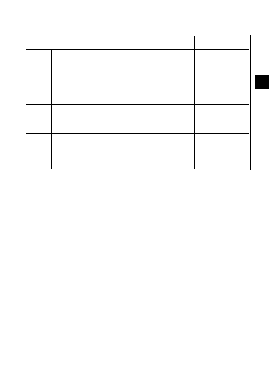
1MRS751861-MEN
COM 500
71
Configuring MicroSCADA for DNP V3.00
Slave Protocol
Configuration Guide
4. Technical description
4
80
1
Internal Indications
1
2
All
00,index=7
81
1
Storage Object
82
1
Device Profile
83
1
Private Registration Object
83
2
Private Registration Object Descriptor
90
1
Application Identifier
100
1
Short Floating Point
100
2
Long Floating Point
100
3
Extended Floating Point
101
1
Small Packed Binary-Coded Decimal
101
2
Medium Packed Binary-Coded Decimal
101
3
Large Packed Binary-Coded Decimal
No Object
13
No Object
23
OBJECT
REQUEST
(slave must parse)
RESPONSE
(master must parse)
Obj
Var
Description
Func Codes
(dec)
Qual Codes
(hex)
Func Codes
Qual Codes
(hex)


1MRS751861-MEN
COM 500
73
Configuring MicroSCADA for DNP V3.00
Slave Protocol
Configuration Guide
Appendix. Configuration examples
DNP Slave in TCP mode
@NET=4
@STA=1
@LINE=1
#SET NET’NET’:SPO’LINE’=35
#SET NET’NET’:SDV(30)=(’STA’,’LINE’)
#SET NET’NET’:SSD’LINE’="TCP"
#SET NET’NET’:SEN’LINE’=3
#SET NET’NET’:SMS’LINE’=’NET’
#SET NET’NET’:SPD’LINE’=0
#SET NET’NET’:SLK’LINE’=15
#SET NET’NET’:STI’LINE’=3
#SET NET’NET’:SPS’LINE’=50
#SET NET’NET’:SLA’LINE’=0
#SET NET’NET’:STW’LINE’=0
#SET NET’NET’:SIU’LINE’=1
#SET NET’NET’:SIU’LINE’=0
#SET STA’STA’:SAL=1
#SET STA’STA’:SDR=1
#SET STA’STA’:SIA="62.236.144.119"
#SET STA’STA’:SSA=’STA’
#SET STA’STA’:SMA=10
#SET STA’STA’:STT=25
#SET STA’STA’:SCT=10
#SET STA’STA’:SRT=30
#SET STA’STA’:SPC=1
#SET STA’STA’:SRM=4
#SET STA’STA’:SIU=1
#SET NET’NET’:SIU’LINE’=1
DNP Slave in UDP mode
@NET=4
@STA=1
@LINE=1
#SET NET’NET’:SPO’LINE’=35
#SET NET’NET’:SDV(30)=(’STA’,’LINE’)
#SET NET’NET’:SSD’LINE’="UDP"
#SET NET’NET’:SEN’LINE’=3
#SET NET’NET’:SMS’LINE’=’NET’
#SET NET’NET’:SPD’LINE’=0
#SET NET’NET’:SLK’LINE’=15
#SET NET’NET’:STI’LINE’=3
#SET NET’NET’:SPS’LINE’=50
#SET NET’NET’:SLA’LINE’=0
#SET NET’NET’:STW’LINE’=0
#SET NET’NET’:SIU’LINE’=1
#SET NET’NET’:SIU’LINE’=0
#SET STA’STA’:SAL=1
#SET STA’STA’:SDR=1
#SET STA’STA’:SIA="62.236.144.119"
#SET STA’STA’:SSA=’STA’
#SET STA’STA’:SMA=10
#SET STA’STA’:STT=25
#SET STA’STA’:SCT=10
#SET STA’STA’:SRT=30
1MRS751861-MEN

74
1MRS751861-MEN
Configuring MicroSCADA for DNP V3.00
Slave Protocol
COM 500
Configuration Guide
#SET STA’STA’:SPC=1
#SET STA’STA’:SRM=4
#SET STA’STA’:SIU=1
#SET NET’NET’:SIU’LINE’=1

COM 500
Index
Configuration Guide
Index
Page
$
AA
AC
ADDR
AF
AI
AL
Allocating Application
Allocation
AN
Analog
&KDQJHHYHQWV
,QSXWV
6HWSRLQWV
APDU
Application Layer Attributes
......................................................................................... 17
Application Message Data Retries
................................................................................ 20
AR
AS
AT
AT command
Autocaller AT S Register
............................................................................................... 28
Autocaller Enabled
Autocaller State
%
Baud Rate
BI
Binary
&RXQWHUV
,QSXW
2XWSXW
BL
BR
Buffer Pool Size
&
CA
CF
CL
Classes
CN
Cold restart
Collision
COM 500
Command
&RQILUPDWLRQ
3URFHGXUHV
Command Address
Communication
0RGHV
1MRS751861-MEN
Configuring MicroSCADA for DNP V3.00
Slave Protocol

1MRS751861-MEN
Configuring MicroSCADA for DNP V3.00
Slave Protocol
COM 500
Index
Configuration Guide
Configuration
Confirmation Timeout
Connected Station
Connection
Connection Time
Connection Time Limited
............................................................................................. 26
Control relay output block
................................................................................36
Counter events
Cross-reference information
......................................................................................... 43
CS
CT
CTS
'
Data flow
Data object type
Data point address
Database Initialised
DC
DCD
DCD signal
DD
DE
Delay measurement
DESTINATION address
............................................................................................... 41
Device profile
DFC
DI
Diagnostic Counters
................................................................................................ 16
Direction
DNP V3.00 slave
&20
DNP V3.00 slave protocol
.............................................................................................. 5
Double indications
DR
(
EN
Enhanced Protocol Architecture (EPA)
......................................................................... 35
Enquiry Limit
ET
EV
Event channel
............................................................................................. 42
Event data
Event Data with Time Stamp
........................................................................................ 46
Execute Waiting Time After Select
............................................................................... 25
)
Fatal error
Flag byte
Frozen counters
Function code

1MRS751861-MEN
COM 500
Index
Configuring MicroSCADA for DNP V3.00
Slave Protocol
Configuration Guide
+
Handshaking
Header Timeout
Hostname
HT
,
IA
IEDs
IL
IN
In Use
Index
Information Address Length
......................................................................................... 20
Input data
Intelligent Electronic Devices
....................................................................................... 35
Internal Indications
..................................................................................................23
Internet Address
Interrogation
IOA
IP address
IU
IU attribute
/
LA
LI
Line Number
Link Layer Attributes
Link Layer Confirmations Enabled
............................................................................... 16
Link Service Data Units (LSDU)
.................................................................................... 9
Link Type
LK
LPDU
LSDU
0
MA
Master Address
Maximum Delayed Response Time
.............................................................................. 24
Maximum Message Length
.....................................................................................12
Maximum random delay for retransmission
................................................................. 13
MC
Message Application
...............................................................................................15
Message Identification
............................................................................................15
MI
ML
Modem Command
Modem Signal
MS
MT
................................................................................................................................. 24
Multi-drop network topology
......................................................................................8

1MRS751861-MEN
Configuring MicroSCADA for DNP V3.00
Slave Protocol
COM 500
Index
Configuration Guide
1
NCC
NET database
Network Topologies
No limitations
2
OBJ
Object commands
Object Status
Offset
Open Systems Interconnection
...................................................................................... 35
OR
OS
Output data
OV
3
Parity
PC
PD
Physical layer
PO
Point-to-point network topology
................................................................................. 8
Poll Delay
Polled Report-by-Exception Operation
......................................................................... 40
Priorities
Process Data Confirmation
........................................................................................... 20
Protocol
Protocol converter
PS
Pulse counters
Pulse Dialling
Pulse length
PY
4
QL
Quiescent Operation
5
RA
Radio Connection Wait Time
........................................................................................ 27
Radio Disconnection Delay
.......................................................................................... 27
RB
RC
RD
Read, conditional write
Read-only
Receive Interrupt Enable Delay
.................................................................................... 14
Receiver Data Bit Count
............................................................................................... 12
Remote Calls Enabled
Remote host

1MRS751861-MEN
COM 500
Index
Configuring MicroSCADA for DNP V3.00
Slave Protocol
Configuration Guide
Remote Terminal Units
Reply Time-out
Reply Window Size
Request
Reset Event Queues
Response
Response Timeout
Restart bit
REX
REx type
RI
RK
RM
RS
RT
RTS
RTUs
Running Mode
RW
6
SA
SB
SD
SE
Signal rerouting
Signals
Single Indications
Slave Address
SOURCE address
Spontaneous Data
SR
ST
Static data
Static Report-by-Exception Operation
.......................................................................... 40
Status codes
$SSOLFDWLRQ/D\HU
/LQN/D\HU
Stop Bits
Subset levels
SYS 500
SYS Waiting Time
SYS_BASCON.COM
System Device Name
System Messages Enabled
............................................................................................. 19
7
TC
TCP mode
TD
Test function of link
TI
Time Synchronisation
Transmission Wait Delay
............................................................................................... 13

1MRS751861-MEN
Configuring MicroSCADA for DNP V3.00
Slave Protocol
COM 500
Index
Configuration Guide
Transmitter Data Bit Count
........................................................................................... 12
Transport layer
Transport Layer Timeout
............................................................................................... 24
TT
TW
8
UDP mode
UN
Unsolicited messages
................................................................................. 18
Unsolicited Report-by-Exception Operation
................................................................ 40
9
VAR
Variation
:
Warm restart
Wiring
Write-only
;
XR
Document Outline
- Introduction
- Safety information
- Instructions
- Technical description
- Appendix. Configuration examples
Wyszukiwarka
Podobne podstrony:
Configuring MicroSCADA for DNP V3 00 Master Protocol
Configuring MicroSCADA for IEC 60870 5 101 Slave Protocol
Configuring MicroSCADA for IEC 60870 5 104 Slave Protocol
Configuring MicroSCADA for IEC 60870 5 103 Master Protocol
Configuring MicroSCADA for IEC 60870 5 104 Master Protocol
Configuring MicroSCADA for IEC 60870 5 101 Master Protocol
Configuring MicroSCADA for Modbus Slave Protocol
Configuring MicroSCADA for Modbus Master Protocol
Configuring MicroSCADA for OPC DA Client
23 299 318 Optimizing Microstructure for High Toughness Cold Work Steels
23 299 318 Optimizing Microstructure for High Toughness Cold Work Steels
End to end security implementation for mobile devices using TLS protocol
Confocal optics microscopy for biochemical and cellular high throughput screening by Lenka Zemanová,
37 509 524 Microstructure and Wear Resistance of HSS for Rolling Mill Rolls
Installing WSUS for Configuration Manager 2012 R2
00 Mechatronics of Electrostatic Microactuators for HD
Słownik, ACPI (Advanced Configuration and Power Interface): Standard zarządzania energią wypracowany
Słownik, ACPI (Advanced Configuration and Power Interface): Standard zarządzania energią wypracowany
więcej podobnych podstron