
INK
Change is Not in the Cards
0
ne of my favorite lines from a movie
was uttered by Dr. McCoy in Star Trek:
The Motion Picture. “I know engineers.
They love to change things.”
By now, I’m sure you’ve noticed some changes in our
look. Our last major redesign was over two years ago, and
really didn’t involve more than the cover and some minor
details inside. As we enter our fifth year of publication, a
fresh look is in order to spice up our presentation a bit.
Rest assured our content hasn’t changed (and won’t
change anytime soon). We engineers may like to change
things, but only if the change is for the better. We’re having
too much fun the way things are.
A BUILDING AUTOMATION EXTRAVAGANZA
What better way to kick off our fifth year than with an
issue jam-packed full with home automation articles.
Always a popular topic with our readers, this issue is also
our largest so far.
The cornerstone of the issue is a tale of home automa-
tion gone awry, written by perhaps the most famous home
automatist, Steve Ciarcia, where he also introduces the new
Circuit Cellar Home Control System II. Other articles
detailing system building blocks are also presented by Ed
Nisley and me.
You might start to wonder, if we’re spending so much
time covering technologies such as CEBus,
and
SMART HOUSE, why are we suddenly designing our own
home control system? You have to be careful not to get the
two types of systems confused.
Systems such as CEBus and SMART HOUSE are
actually home networks. They provide communication
media and protocols, but don’t really deal with the issue of
control. Small CEBus installations may be able to be done
with no central controller. However, we feel in most
installations, some central controller will still be necessary.
The HCS II addresses primarily the control side of a
home automation installation. We use X- 10 for power line
and RS-485 for twisted pair, but only because those are
network technologies that are available at reasonable cost
today. When CEBus devices start showing up on store
shelves, we’ll be able to connect a CEBus interface to the
supervisory controller and add CEBus to the list of sup-
ported networks (and indeed replace X-10 and RS-485).
So don’t think we’re a bunch of rebels bucking the
trends you see unfolding in the news, on TV, and even
within these pages. We’re simply using today’s technology
so we can be ready when tomorrow’s finally shows up.
THE COMPUTER
APPLICATIONS
JOURNAL
DIRECTOR
Steve Ciarcia
MANAGING EDITOR
Ken Davidson
ASSOCIATE EDITOR
Lisa Nadile
ENGINEERING STAFF
Jeff Bachiochi Ed Nisley
CONTRIBUTING EDITORS
Tom Cantrell 8 Chris Ciarcia
NEW PRODUCTS EDITOR
Weiner
ART DIRECTOR
Lisa Ferry
PRODUCTION MANAGER
Mark Vereb
STAFF RESEARCHERS:
Northeast
John Dybowski
Midwest
Jon
&Tim
West Coast
Frank Kuechmann
PUBLISHER
Daniel Rodrigues
PUBLISHER’S ASSISTANT
Susan McGill
CIRCULATION COORDINATOR
Rose
CIRCULATION ASSISTANT
Barbara
CIRCULATION CONSULTANT
Gregory
BUSINESS MANAGER
Jeannette Walters
ADVERTISING COORDINATOR
Dan Gorsky
CIRCUIT CELLAR INK
is
by
4 Park
20,
CT
(203)
CT
One-year (6
U.S.A.
in U.S.
U.S.
Direct
to Circuit
PA 19398 cdl (215)
914.
to
INK,
P.O.
Cover Illustration by Robert
PA19399.
ASSOCIATES
NATIONAL ADVERTISING REPRESENTATIVES
NORTHEAST
Debra Andersen
SOUTHEAST
Collins
WEST COAST
Barbara Jones
(617) 769-8950
Fax: (617) 769-8982
Barbara Best
(395) 966-3939
Fax:
985-8457
MIDWEST
Nanette Traetow
Shelley Rainey
741-7744
(708) 7893080
Fax: (908)
Fax: (708) 789-3082
HST.
in
of materials
workmanship of
INK
and
d
based
a
descriptions.
Cellar INK.
by
Cellar
All
reserved.
a part
Circuit Cellar Inc. is
2
Issue
February/March, 1992
The Computer Applications Journal
12
The State of Home Systems
by
Parks
14
Take a Tour of the Bright Home
by Ken Davidson
22
The Circuit Cellar Home Control System II
by Steve Ciarcia
46
The Home Control System II Supervisory Controller
by Ken Davidson
Designing with the LM335 Temperature Sensor
by Mark E. Nurczyk, P.E.
Isolation Amplifier Design Using the IL300 Linear Optocoupler
by Bob Krause
Editor’s
Davidson
Change is Not in the Cards
Reader’s INK-Letters to the Editor
New Product News
edited by
Weiner
Firmware Furnace/Ed Nisley
Two-Way Power Line Communication
Practical Algorithms/Charles P. Boegli
Simulating Dynamic System Responses
From the Bench/Jeff Bachiochi
Does It Come With a Memory...Standard?
Silicon Update/Tom Cantrell
Cheap Chips/Lean and Mean PIC Machines
Domestic Automation/Ken Davidson
Goes Coax/Also Visit
the Home of the Future
from the Circuit Cellar BBS
conducted by Ken Davidson
Steve’s Own INK/Steve Ciarcia
The More It Changes, the More It Stays the Same
Advertiser’s Index
The Computer Applications Journal
Issue
February/March, 1992

Don’t Blame the Tool
In response to Thomas
letter,“What
About The Schematic Reader?” in Circuit Cellar INK,
issue
1)
Signal Names:
allows naming of signal
paths. Consistency is up to the layout engineer.
2) Power and Grounds:
gives the user both
the choice of where to place Power/Ground pins and
whether or not they are visible. Power and Ground pins
may be placed on the part. Use of the Line-Draw and
Label functions allows one to make a Power/Ground List
if desired.
3) Block Diagrams:
allows the building of
Hierarchical Schematics. Thus, page one may be a block
diagram of the device in its simplest form. Page two
would be a breakdown of one of the blocks on page one
(this could be a block diagram, a schematic or both).
Labels can identify signal paths. The entire schematic
may be handled this way.
4) Programmable Gate Arrays: Use of the Line-Draw
and Label functions allows one to make a list. Or a
printout of the PGA functionality could be included.
5) Signal Flow:
supports intersheet signals
with Module-Ports. These consist of user-defined text
inside a box. One or both ends of the box may be pointed
to indicate signal flow.
6) Part Locations: This is entirely in the hands of the
layout engineer.
7) Parts Lists:
supports Parts Lists, of course.
Also, each part has eight separate fields. These may be
used for such items as Supplier Information, Part
Substitution Data, Part Tolerance, and so on. Each of
these fields may be made visible or invisible.
I have been using
for all my schematic work
for the past four years. I have used all the features
mentioned here. They are neither difficult to learn nor
difficult to use. Despite its imperfections (yes,
does have some), “ease of use” and “maximum user
choice” have kept me a loyal fan. Thus, I have some
trouble with your rating
a “2 out of 10.” I do
agree that the seven points of yours do need to be
addressed by layout personnel. I too have been forced to
“thrash” through unreadable schematics.
If your layout people are using a recent version of
they have the power to produce readable,
informative schematics. It sounds to me like they are
blaming the tool for their inability/unwillingness to use
it fully. Reminds me of the story of the screechingly
awful violin player, who was convinced he could make
beautiful music if only he had a Stradivarius.
Allen K. Milakovic, Glen Rock, PA
‘Round and ‘Round He Goes
Boy, I’m really getting dizzy. I’ve gotten on and off
the “C merry-go-round” a few times now.
I wanted to learn to use a C compiler for the 805
1
microcontroller. I heard many times that C is the way to
go, so I enrolled in a night-school course at a local
college to learn C programming for the PC, just to get a
taste of it. As it turned out, I found that I had some
difficulty grasping the cryptic mannerisms of C.
I might add that I am usually a determined
starter-type person who normally doesn’t need to be led
by the hand. The talk about C is that it is sort of tough
to learn, so I thought taking the course would be a good
primer. Instead, it left a bad taste in my mouth. It also
left me with the belief that C is ideally suited for
database-type programs and should be left to program-
mers in the business world.
So I jump off the ride.
Keeping in mind that “C is the way to go,” I thought
to myself that perhaps C for embedded controllers might
be easier to learn since I have a reasonable understanding
of the hardware and assembly programming.
I jump back on the ride.
Then I read an article where a comparison of a few C
compilers was made. Wow! The price! At $600 and up,
that’s prohibitive enough to keep me programming in
assembler. It’s only a hobby.
I jump back off the ride.
Then I get all pumped up when I see Ed’s “Firmware
Furnace” in issue
titled “Restarting C.” “That
sounds like my disposition,” I say to myself. (Well,
maybe even not quite restarting it.) I read, “If you don’t
learn C, you won’t be a hit at the party.” Ed also men-
tions an affordable C cross-compiler. I really should give
this a shot.
I jump back on the ride.
As I continued reading the article, I wondered what
the C is really doing other than calling assembly routines
or performing simple tasks that would easily be accom-
plished by assembly code. I try to convince myself to
learn it anyway.
Well, I just received issue
and T.B. Kester’s
letter to the editor (“Taking Ed to Task”) had me jump
off the merry-go-round.”
Wait a minute. “A” is for Assembler, “C” is
don’t want to talk about it. Hey! I missed “B.” “B” is for
BASIC like in BASIC-52. I think I’ll give that some
attention. What the heck! It’s only
C?
Hugh Duff, Toronto, Canada
4
Issue
1992
The Computer Applications Journal
Design Contest Winner Fan
Your recent issue (Circuit Cellar INK, issue
was a pleasure, again. However, there was something
that really caught my eye: the second prize winner in
the open category of the Design Contest.
It was not the device design that fascinated me so
much as the attractive package it was in. Although
noted by the judges, I still think it was not empha-
sized enough. If this was a one-off job, the enclosure
was really terrific!
How about some articles on that subject? Or at
least a note as to how Sanjaya did do the packaging of
his project? This is really a nontrivial matter for us
nonartistic types. For example, quite often I have to
come up with a prototype or a proof-of-concept device.
It works right, but with the looks of it... And nice
packaging shows a design off as much as its function-
ality.
Robert Walker, West Orange, NJ
Our Design Contest winners always generate a
great deal of interest from our readers, in phone calls,
letters, and BBS messages. A point we tried to make
in the introduction, but apparently not succinctly
enough, is most of the design contest winners, and
many of the entrants that didn’t win, will be writing
complete articles about their projects. The articles
will be appearing in the pages of upcoming issues of
The Computer Applications Journal and in future
volumes of “The Circuit Cellar Project File.”
EPROM emulator is slated for the next
volume of the project file, as is Alan Rauscher’s XYZ
drilling table (about which we’ve had many calls).
I also want to stress that, in the interest of our
entrants’privacy, we won’t give out their addresses or
phone numbers unless they’ve given us permission to
do so. If you’re looking for more information about a
project and can’t wait for it to be published, write a
letter to the designer and send it to us here at the
magazine. We’ll be sure to forward it.-Editor
Correction
In issue
[December ‘9 1, January
“Firm-
ware Furnace,” the EPROM data lines (00-07) should
be connected to the other side of the
(U2) in
Figure 3.
We Want to Hear from You
Send letters of praise, condemnation, or sugges-
tion to the editors of The
A p p l i c a t i o n s
Journal.
The Computer Applications Journal
letters to the
4
Park Street
Vernon, CT 06066
TIM
liquid Crystal
Displays
16 Characters x 1 line
3
40
Characters x 2 line 2 for
. . . . . . . . . . . . . . . . . . . . . . . . . . 32
20x2512’
24 Characters x 2
line LCD
In C-MOS LCD
98
ADAPTEC
Controller,
your
choice
DIODE
at
$ 5
BOARD
links 3270
mainframe
la IBM
MAGNETIC CARD READER
K
1.2
Mb
K
1.44
Mb
$7
640
computer.
board to generate text ond
o
LCD.
be very familiar wiring
when
640 x 400
POWER SUPPLY
NECARGON
(avg).
laser
Optical Laser Array
Call for
package
Magnavox
color monitor
$150.00
1
Drive
20Mb Hard Drive
CDC 94166-141
Non-Enclosed Monitors
Black &
7 inch. . . . . . . . . . . . . . . . . . . . . . $29.95
9 inch (Amber) . . . . . . . $29.95
Graphic
480
Dot 128 Dot
each,
2 20.1
$24.00
CONTROLLER CARD
Xl
hard drtve controller
AT
Hard Drive
16
8 0 3 8 7 - s
are
b work al desired
1
Model
Token Ring Board
BOARD $79.
included,
to
on
(256x9
Floppy
Controller
2
serial ports and 1 parallel port
input
Output
Has
S
C
S
I
controller Socket
controller)
the size of
5.25” floppy
ME
IN THE SKY
1726 element CCD $19.00
4096 element CCD $29.00
The
Computer Applications Journal
Issue
February/March, 1992
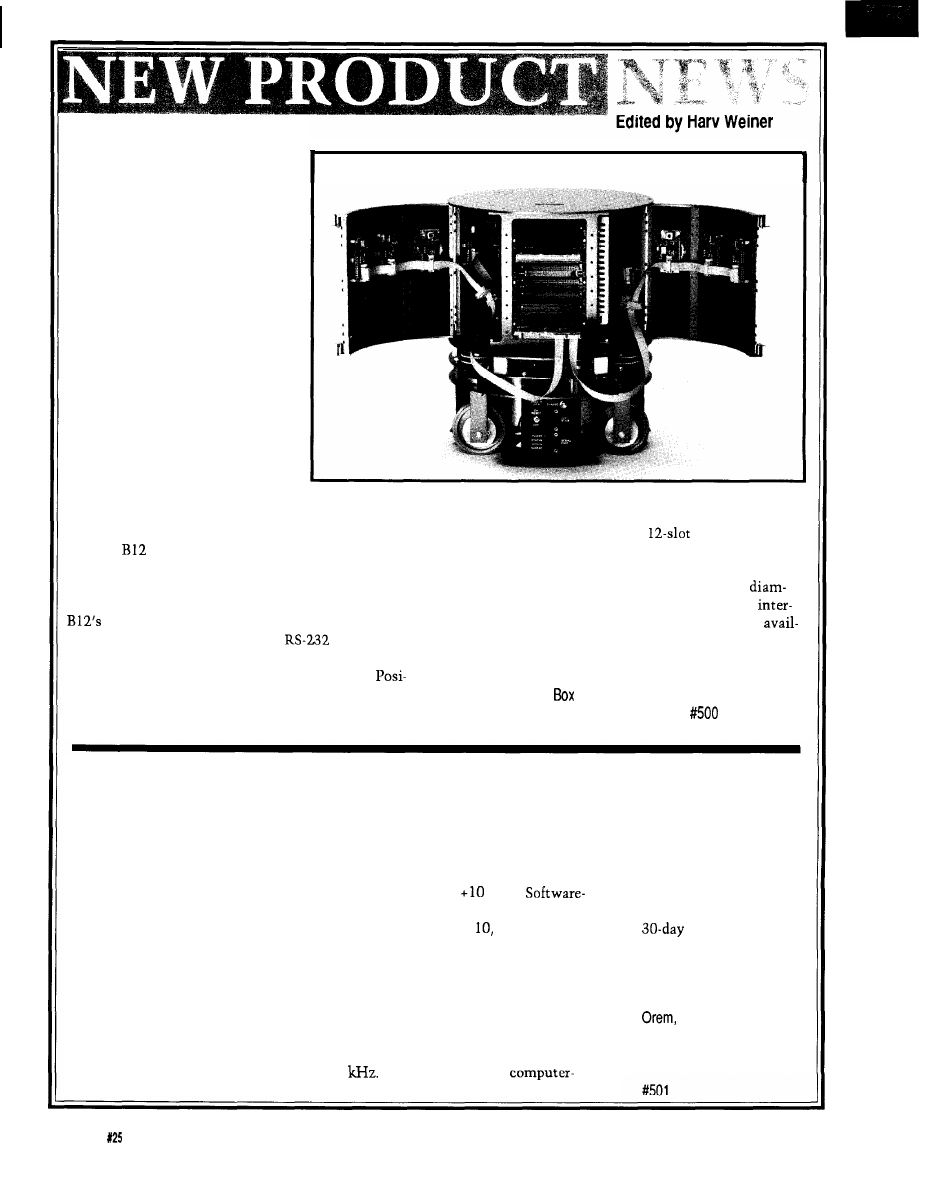
MOBILE ROBOT
Home automation reaches new
levels with a self-contained
interactive mobile robot base from
Real World Interface Inc. The B 12
Series is a modular system,
available with off-the-shelf compo-
nents to speed research projects.
The B12 Mobile
Robot
contains
motors, power amplifiers and an
on-board control computer and
software in a rugged aluminum
frame. The base measures 6.75”
high by 12” diameter, weighs only
25 pounds, and can carry a payload
up to 40 pounds. Its small size
alleviates the inconvenience and
potential hazards of larger robots,
while its low center of gravity
allows it to climb steep inclines and travel at speeds of
A total access Development Enclosure with card
up to 6 feet per second.
cage, power supply system, and
backplane is
The
Robot significantly reduces prototyping
available, and it accommodates various compatible
time and cost of mobile robotic systems because of its
computer boards as well as sonar drives and transducers.
size and ability to conform to a variety of application
The standard enclosure measures 8” high by 12”
requirements. The programming environment of the
eter and features 48 potential sensor sites on four
control software uses simple mnemonic language
changeable door frames. A 68000 computer card is
that translates through a standard
serial port into
able for both on-board control and sensor processing.
precise real-time positioning. Synchro drive mechanics
allow each servo loop to be operated in Velocity,
Real World Interface, Inc.
tion, Power, and Limp modes. Each servo mode can be
Main Street
l
P.O.
270
changed at will, even when the B12 is in motion.
Dublin, NH 03444
l
(603) 563-8871
DATA ACQUISITION SYSTEM USES PARALLEL PORT
DAS Inc. announces
a low-cost data acquisi-
tion system that uses the
parallel port of a standard
personal computer
parallel port.
Easy Data
eliminates the need and
fuss of screwdrivers,
jumpers, and interrupts
typically required for
data acquisition hard-
ware by providing an
external unit that plugs
directly into the parallel
port. The hardware and
software supplied with the
system is user friendly,
requiring only a few
minutes of setup and
familiarization time before
acquiring data.
Performance specifica-
tions for the Easy Data unit
rival those of systems
costing two or three times
as much. The unit can
acquire up to 16 signals
simultaneously with a
nominal single input
throughput of 4
Input
polarity is software select-
able for unipolar or bipolar
operation, with a measur-
able voltage from -10 volts
to
volts.
selectable gains are in steps
of 1, 100, or 1000.
As an added feature, the
Easy Data unit has a single
analog output capable of
producing pulsed, square,
ramp, or triangular waves,
giving it many of the
features found only in
expensive
controlled signal genera-
tors.
The Easy Data unit
sells for $269 and
includes the graphics
oriented software and a
money back
guarantee.
DAS, Inc.
1034 Industrial Park Road
UT 84057
(801) 224-8080
Fax: (801) 224-8087
6
Issue
February/March, 1992
The Computer Applications Journal
NEWS
Every measurement is automatically given a serial
number, and a marker can be assigned. Internal data
compression ensures only changes in measured values
take memory space, so the RAM usage is economically
managed.
The Data Logger includes two sliding switches, one
rotary switch (with 16 positions] and two push buttons
that can be used for any application. An internal, mag-
netically activated reed switch, with external magnet
is also included. The Data Logger accepts any voltage
between 6 and 48 VDC or AC (with optional voltage
input) and stores every key press and every change in
switch status along with the relevant time.
The Data Logger sells for $299 for the
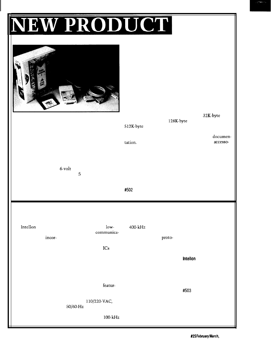
VERSATILE LOW-COST DATA LOGGER
model and $419 for the
model. The price of the
model is available on request. Each unit is
Obtain a low-cost approach to real-time data capture
supplied with a universal software package, serial
with a novel
Data Logger
system from W&T Products
connecting cables for an IBM PC, and complete
Corp. Traditional data loggers usually involve the wiring
Also available are a variety of plug-ready
of numerous terminals and sensors, but the W&T Data
ries, including a footswitch, a passive infrared detector,
Logger are installed only where needed and without
vibration sensors, humidity sensors, and temperature
wires.
sensors.
The calculator-sized unit operates approximately
200 days on a disposable
lithium battery, and
W&T Products Corp.
features memory sizes from 32K to 12K bytes. It records
2209
NE 54th Street
l
Ft. Lauderdale, FL 33308
up to eight analog values, and captures changes in the
(800) 628-2086
l
Fax: (305) 351-9099
switching state of up to eight internal switches (external
switches can be connected) and an external voltage.
CEBUS POWER LINE INTERFACE PRODUCTS
is pleased to
may be used to bring
to
range to allow
or compatible. The
announce the availability
cost power line
development of networks
system is available for
of three products
tions to a broad range of
utilizing the CEBus
$3495. Additional nodes
porating its revolutionary
products. It is available in
col. The SSC PLCEMO is
for the evaluation system
Spread Spectrum Carrier
sample packs of six
as
available in sample packs of
are available for $995.
technology for use with
part number SSC
two modem boards for $500
the Electronic Industries
PLCEFNPAK for $300.
as part number SSC
Corporation
Association’s CEBus: the
Production quantities are
PLCEMOPAK. The SSC
5150 West Highway 40
SSC
PLCE power line
priced at less than $5
PLCEMO is priced at $105
Ocala, FL 32675
modem IC, the SSC
(25,000).
each in quantities of 10.
(904) 237-7416
PLCEMO power line
The SSC PLCEMO is a
The SSC EVS-PL is a
Fax: (904) 237-7616
modem board, and the
board-level product
complete system for
SSC EVS-PL evaluation
ing the SSC PLCE, transmit
evaluating the performance
system.
amplifier, and coupling
of CEBus power line
The SSC PLCE is
circuit for
networks. The system
Intellon’s power line
power lines. The
includes three complete
modem integrated
SSC PLCEMO is configured
CEBus nodes and control
circuit. The SSC PLCE
for operation in the
software for an IBM PC/AT
The Computer Applications Journal
Issue
1992
7
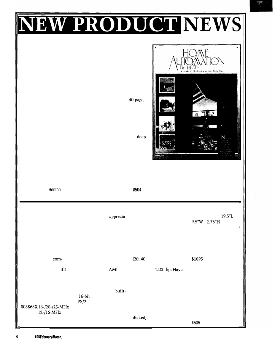
HOME AUTOMATION CATALOG
Exciting, innovative electronic products for the home, yard,
and automobile are featured in Heath Company’s latest Home
Automation by Heath Catalog.
Home Automation by Heath contains a wide variety of
consumer products designed for safety, security, convenience,
entertainment, and energy management. These products are
designed to create a home environment that is a safe, pleasant,
convenient, easy to manage, and energy efficient.
The newest issue of Home Automation by Heath is a
full-color catalog aimed at the do-it-yourself home enthusiast as
well as the electronics innovator. The Holiday issue introduces
many exciting new products, such as drape controllers, air cleaners,
gas detectors, and wireless light switches. Use the electronic drape
controller to control drapes by a handheld remote, programming
them to open or close at predetermined times throughout the day.
The catalog features three new air cleaners that electronically
clean the air. The gas detector sounds a powerful alarm in case of a
poisonous or explosive gas leak. And for the homeowner, the
wireless add-on switch is perfect for stairways, long hallways, or
large rooms needing a light switch at both ends.
Other products offered in the catalog include whole house
automation and security systems, motion-sensing indoor and outdoor lighting controls, timers, security cameras,
wireless video broadcasters, energy-saving thermostats, and much more.
Heath Company
Dept. 350-058
l
Harbor, MI 49022
(800) 444-3284
THE ULTIMATE
The system is
with external ports for bar
dimensions are
x
SPACE SAVER
bly smaller than any
code reader or scanner and
x
(rear),
standard computer and
floppy/tape drives.
1.25% (front). The unit is
Computer users who
offers virtually the same
Some of the optional
shipped in an attractive
lack desktop space will
power, memory, and
features available are an
suitcase-style cardboard
appreciate the new
expansion capabilities. The
80287 or 80387 math
container.
computer announced by
standard system includes an
coprocessor, 32K cache
Suggested list price
LinkSys Corp. The
on-board CPU, 1 MB DRAM
buffer, internal floppy and
for the system starts at
KeyboardPC is a
(expandable to 16 MB) with
and 60 MB) hard
and optional
plete 386SX computer
autosensing memory
drives, external floppy or
features are priced
built into a standard
expansion, and an
tape drives,
separately. The system
style keyboard. The
keyboard and main system
compatible modem, and a
comes with a 3-year parts
system operates either as
BIOS. It also uses a 1024 x
LAN card. The choice of
and labor warranty.
a stand-alone unit or as a
768 super VGA interface, an
having the system shipped
local area network
IDE disk controller, a
with standard disk drives or
LinkSys Corp.
workstation, and it can
in
LAN card slot, and
without the ability to add
P.O. Box 18558
be configured with an
a
mouse.
drives is one unique feature.
Irvine, CA 92713
Standard internal ports
The KeyboardPC
(714) 261-1288
or 80286
include one game, two
weighs just 9.3 pounds fully
Fax:
(714) 261-8868
CPU.
serial, and three parallel,
and its overall
Issue
1992
The Computer Applications Journal
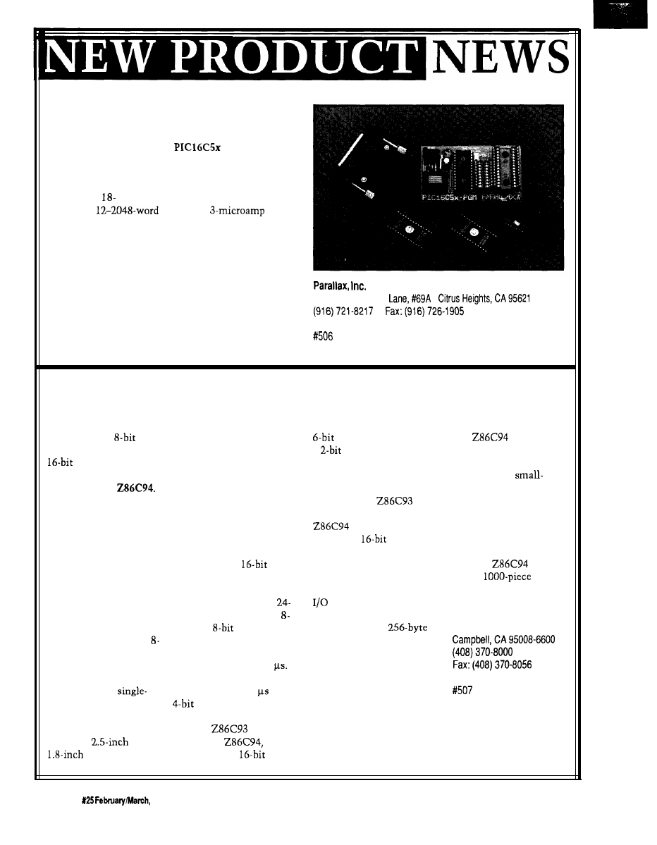
LOW-COST MICROCONTROLLERS
A series of versatile, low-cost microcontrollers is
available from Parallax. The
series is a family
of eight-bit CMOS devices that combine EPROM
technology and a fast CPU with bit and byte addressing
for all I/O pins and registers. The PIC family of control-
lers features
and 28-pin packages, 12 or 20 tristate
I/O lines, 5
EPROM, a
sleep
mode, and DC-to-8-MHz clock.
A comprehensive set of PC-based tools are also
available and include an assembler, a programmer, and
an emulator.
The price of the PIC microcontrollers ranges from $3
to $5 in one-time-programmable packages, and from $17
to $26 in erasable packages. The PIC programmer sells
6200
Desimone
l
for $199, the emulator for $299, and the programmer and
l
emulator for $449. The assembler is included with the
hardware.
MICROCONTROLLER FEATURES ON-BOARD DSP
Zilog announces the
industry’s first
microcontroller with a
digital signal
processor (DSP) on a
single chip, the
The addition of DSP to
the company’s Z8
microcontroller permits
closed-loop servo
functions to be executed
digitally, reducing cost
and eliminating noise
and reliability problems
associated with analog
servos.
The device also
features extremely fast
bit analog-to-digital and
digital-to-analog convert-
ers, a serial peripheral
interface, and a
channel pulse-width
modulator. These
features make it ideally
suited for
and
disk drives as
well as tape drives, voice/
data processing, and
sophisticated automotive
and consumer electronics.
The on-chip DSP
operates as a slave processor
to the Z8 and is used in
applications requiring
extensive math calcula-
tions. When executed from
DSP program RAM, it is
capable of 16 x
multiplication and accumu-
lation in one clock cycle, or
less than 100 ns with a
MHz system clock. The
channel,
A/D con-
verter is a half-flash con-
verter with a maximum
conversion time of 1.7
The 8-bit D/A converter has
a settling time of 3
and a
digitally controlled
gain stage.
The
Z8 core,
used in the
contains three
counter/timers, two with a
prescaler and one with
a
prescaler to improve
timing flexibility. One of
the counter/timers has five
capture and three compare
registers. The
math
unit is retained on the
and allows
hardwired
multiplica-
tion and division at lower
speeds for less time critical
math functions.
The Z8 also includes 24
lines, up to 64K bytes of
addressable external
program space, a
register file, and 236
general-purpose registers.
The on-chip oscillator
accepts a crystal or external
clock drive. A UART is
included for asynchronous
serial communications and
an industry-standard serial
peripheral interface is
included for synchronous
serial communications.
The
has three
power-down modes for
power-sensitive applica-
tions, such as
form-factor disk drives in
notebook computers. It
also supports both
multiplexed and
demultiplexed address/
data buses.
The
sells for
$15 in
quantities.
Zilog, Inc.
210 E.HaciendaAve.
1 0
Issue
1992
The Computer Applications Journal
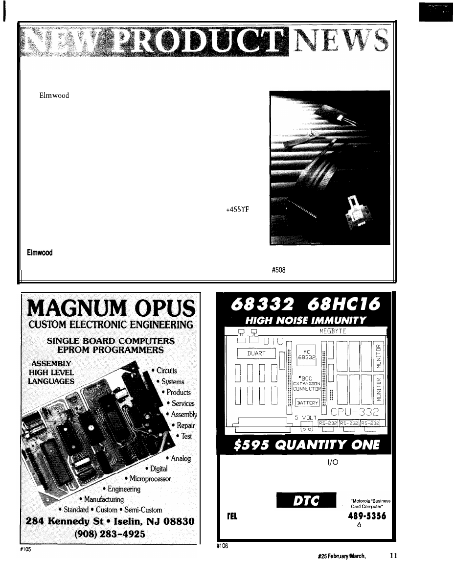
FLEXIBLE TEMPERATURE SENSORS
Sensors Inc. introduces a line of flexible temperature sensors
that make measuring the temperature of curved, cylindrical, and conical
surfaces easy. Flexible Temperature Sensors conform to a variety of surfaces
and provide complete surface-to-surface contact. Their ability to sense the
temperature of an entire surface area, rather than a single line or point
contact, ensures a fast, reliable response to surface temperature changes.
The sensor achieves flexibility through the use of either an etched foil
or wire-wound sensing element. The element is encapsulated between
layers of flexible, moisture resistant, dielectric materials, such as Kapton or
silicone rubber. The sensors can also be manufactured on transparent film
dielectrics, such as polyester.
Pressure-sensitive adhesive allows for press-in-place installation and
improves performance by eliminating the need for thermal grease or epoxy.
The sensing elements have a temperature range of 328°F to
and are available in platinum, nickel, or nickel-iron with various tempera-
ture coefficients of resistance. The three-wire lead configuration negates
lead wire resistance. A price was not available at press time.
Sensors, Inc.
500
Narragansett Park Drive
l
Pawtucket, RI 02861-4325
(401) 727-1300
l
Fax: (401) 728-5390
ONE
RAM/EPROM
r - l
-
-
-
l
I/O CONNECTOR
D I N T Y P E C
Our FOUR layered CPU and
boards are
designed for tough factory floor environments.
Custom design and board mfg. available.
Please call for specifics.
(510) 475-8147
l
FAX (510)
33476 Alvarado-Niles Blvd., Suite
Union City, CA 94587
The Computer Applications Journal
Issue
1992
‘URES
The State of
Home Systems
Take a Tour of the
Bright Home
The Circuit Cellar
Home Control System II
The Home Control
System II Supervisory
Controller
The State
of Home Systems
Parks
ome automation
an effect rather
an a product: it is a
major benefit expected
from the proliferation of advanced
systems and products in the home
capable of sharing control and data
messages via home networks. Ideally,
and over time, our homes will adapt to
the way we live in them while we live
in them. Of course, this adaption re-
quires expert system software that
can’t be developed in any sophisticated
manner until networks exist for test-
ing and evolution.
detailed in Circuit Cellar
INK
issues 15, and 21, is close to
release. What remains is a bit more
debate over whether adequate levels of
testing have occurred for the power
line spread spectrum solution. Eche-
lon’s
is being used by sev-
eral companies for product develop-
ment. SMART HOUSE, a full system
for new construction, will roll out in
1992. The message behind these state-
ments, regardless of one’s preference,
is home networks are a reality. The
will contain the proliferation of
networked products in the home.
Indeed, the market is not waiting,
although it is Parks Associates’ view
that no broad-based market can occur
for central controllers until home
owners have both more awareness and
more comfort with these systems.
However, there are companies who do
make such offerings currently. Unity
Systems of California has emerged as
the leader in central home automation
systems with its Home Manager, its
acquisition of Hypertek’s Home Brain
technology, and, to be blunt, its sur-
vival in a tough early market.
12
Issue
February/March, 1992
The Computer Applications Journal
Home Automation Inc. is growing.
It markets its system primarily as one
for security that offers extra benefits
beyond burglar alert.
X- 10 (USA) Inc. controllers con-
tinue to proliferate and offer simple
benefits, such as automatic lighting
and timed responses from appliances
including coffee makers and stereos.
new product: The Meter Minder. The
Meter Minder works with
secu-
rity system and allows electric utilities
to read meters automatically and do
load control as well as conduct tradi-
tional security monitoring.
Telecommunications equipment
and services will explode by the end of
this decade. With restraint relief
Of equal note is
the proliferation of
intelligent subsys-
tems from manufac-
turers in established
categories. These
companies are taking
traditionally separate
components and
integrating them.
The most obvious
area of growth is
home theater. The
integration of audio
and video into
systems offering
superior experiential
benefits as well as
distributed sourcing
Dual income families and single
working parents are now a staple of
America. These families are tired.
They want hassle-free equipment (au-
tomatic) they can easily understand
and use. These families are also busy.
Retreating to home on weekends is
deemed a luxury and a desire. Enter-
taining at home is becoming popular
again, which is good
for all sorts of prod-
ucts including home
theater and fancy
systems. Home the-
ater is also viewed by
many consumers as
an excellent approach
to shared family time
at home.
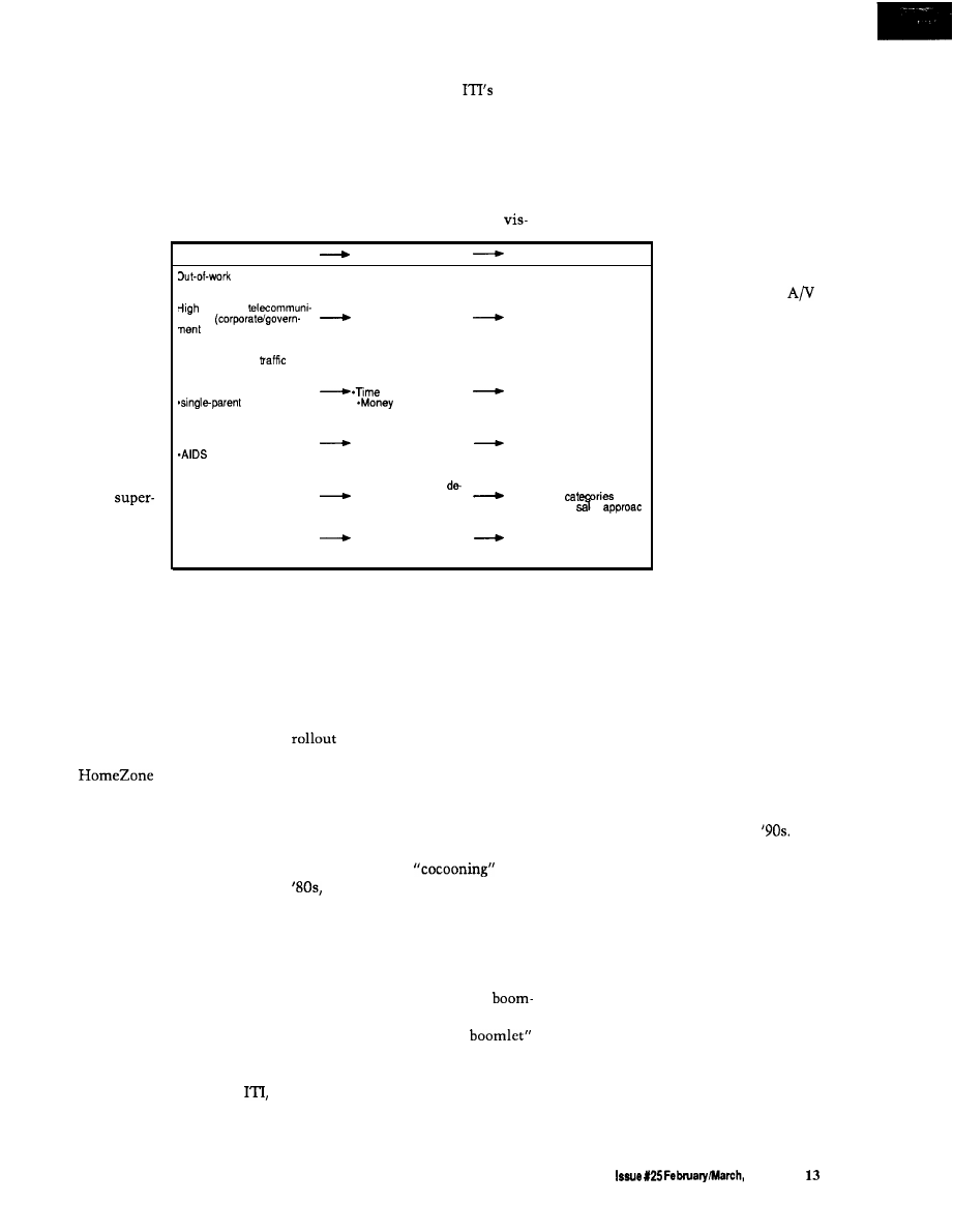
Consumer Trends
Consumer Actions
Consumer Purchases
middle (stream-
ining of corporate America)
*Office equipment
growth in
*Telecommunications
cations
Work at home
control equipment
push)
-Multiple lines
Desire to spend more time
with family out of
*Integrated user interfaces
Increase in
*Convenience
*Premium on easy-to-use or
*dual-income families
savers
automated systems
families
savers
*Diagnostics and PM
programs
Fear/anxiety about
“outside world”
Leisure time at home
Security systems
-crime
(“armored cocoon”)
-Entertainment systems
(home theater, whole
*pollution
house sound)
Rational purchasing
‘Customization” of
*Intelligent subsystems
Personal style
sired systems (variable,
across all
persona options)
*Consultative es
Concern for “earth”
Rising energy costs
Air quality concerns
-Increase house energy
Zoned HVAC systems
efficiency
Efficient units
*Purify air
Better controls
Air quality features
is occurring rapidly. While home the-
ater remains too esoteric for most
consumers’ budgets, it is certainly not
too esoteric for their tastes. Every
major entertainment manufacturer is
entering this arena. With volume,
equipment prices will drop, enabling
more families to afford home theater.
In energy, both Carrier and
Lennox are offering zoning systems.
Carrier’s
provides for up to
four zones of HVAC off one heat
pump, internal diagnostics, remote
dial-out to a central station, and even
electric utility pricing signals. Har-
mony, Lennox’s new offering, also
offers four zones and internal diagnos-
tics. Each of these companies is taking
back the control function traditionally
left to control manufacturers to allow
smoother integration of functions and
enhance consumer benefits.
ible for the Regional Bell Operating
roles is important to consumers. Fif-
Companies, ISDN will finally emerge.
teen percent of American homes have
So will new consumer services and
two telephone lines. Many
equipment that allow consumers to
homeowners would love to be able to
comfortably use these services. Parks
distinguish their telephone calls by
Associates believes it will take our
type. For example, knowing if an in-
giant telephone companies another 12
coming call is business, social, or fam-
to
18
months to begin effective market
ily in nature before you answer would
of new offerings, but they will
be nice. ISDN will emerge in the ’90s
do it and they will do it well for the
[finally) and will bring with it this
most part.
capability for busy families.
Just as important to the process of
home system penetration during the
’90s are the reasons why consumers
want these systems. Faith Popcorn,
coiner of the term
in the
postulates that the ’90s will be
the era of the “armored cocoon.” Our
consumer research echoes her belief.
Consumers want to spend more
time at home than they did in the ’70s
and ’80s. Reasons for this trend in-
clude the consequence of baby
ers approaching or reaching 40 years
old; the result of the “baby
(couples in their thirties having chil-
dren); the reaction to scary external
conditions ranging from pollution to
crime to AIDS; and the shift in values
towards those more family oriented.
In sum, the integration of func-
tions to create more and better sys-
tems will occur rapidly in the
This development will be possible
because home networks will be avail-
able. The pricing of technological parts
will continue to decrease, and consum-
ers will want the benefits of these
types of systems to make their lives
easier and to make living at home
more comfortable, more convenient,
and safer.
q
In security, several companies are
expanding their systems to link to
automatic lighting and remote (away
from home) status, and even add con-
trol capabilities. Some are crossing
categories into entirely new areas.
the leading manufacturer of wireless
security systems, has announced a
Most American
families desire privacy
from outsiders while
at home. Consumers
will subscribe to auto-
matic number identi-
fication as it becomes
available. Also, man-
aging a variety of life
Tricia Parks is president of Parks
Associates in Dallas, Tex. Tricia
provides information to industries
that serve residential environments
with technologically advanced
products, systems, and services.
The Computer Applications Journal
1992
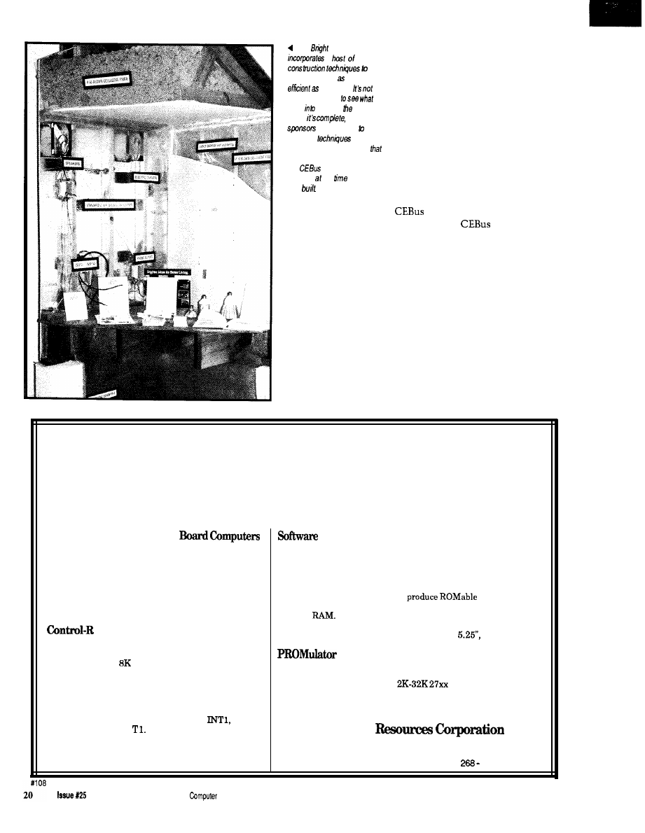
Take a
Tour of the
Bright
Home
Ken Davidson
update article
Update: More
Physical Details Available,” Circuit
Cellar
INK
I briefly introduced
the Bright Home and made a comment
that perhaps a trip to Indianapolis
could be arranged. Well, enough of the
right people were listening, and I soon
found myself Indiana-bound. I took
lots of pictures while visiting the
Bright Home, so allow me to show you
around.
The Bright Home was the first
home demonstration of
technology open to the public. The
was actually a model home in a
new development on the outskirts of
Indianapolis. The builder for the
development used the house to show
prospective buyers what they could
expect if they signed on the dotted line
to begin their own construction. The
home offered much more than your
typical model home, however.
Sponsored in part by Indianapolis
Power and Light Company and PSI
Energy, the home was a showcase for
the latest in energy-saving devices and
building techniques. The house was
built with every conceivable joint and
crack sealed with a plastic vapor
barrier or expanding foam. Even the
holes used to run wires and pipes
through the wall studs were sealed
with foam. Walls were insulated to
than R-19, and the attic was
insulated to better than R-50 [the
typical Indianapolis attic is insulated
to R-30).
An electric heat pump was
installed to do all the heating and
cooling of the house, and officials
expect to keep the house comfortable
year-round for an average of $ per
month (electricity is cheaper in the
Indianapolis area than in much of the
country, so this difference must also
be taken into account). Fluorescent
and halogen lighting were used
throughout the house to further save
electricity.
My interest in the Bright Home
wasn’t its novel building techniques,
though. Part of the overall energy
management scheme included
house automation using
devices. During the construction
phase, a pair of coax cables and
pair twisted wire were run to each
room in the house, all converging at a
central location in the basement. Extra
power outlets were also installed
around the perimeter of each room and
in other strategic locations throughout
the house (more on these outlets later).
Visitors to most model homes
simply wander through the house,
perhaps with a salesman in tow
pointing out specific features that
make his home the best in the market.
With all the extra features found in the
Bright Home, most people either
would be overwhelmed by all the new
gadgets or, more likely, wouldn’t
notice them because they were so well
integrated into the house. Visitors to
the Bright Home are greeted by a fully
scripted performance, complete with
actors and staged events.
I really should say “visitors were
greeted” because public viewing ended
in September, 1991. At that time, the
family who actually purchased the
house took possession of it. Because
your chance to see the action in person
has passed, I’ll stage the performance
to the best of my recollection and take
you through the house myself.
ACT
The drama unfolds as we approach
the front door. Ringing the doorbell,
we are greeted by a voice from a
speaker next to the door, which
explains that “Mrs. Jones” is on the
phone at the moment, but the house
will let her know we are waiting and
she’ll be right out. Momentarily, the
door opens and an apologetic Mrs.
Jones greets us to “her” home.
1 4
Issue
1992
The Computer Applications Journal
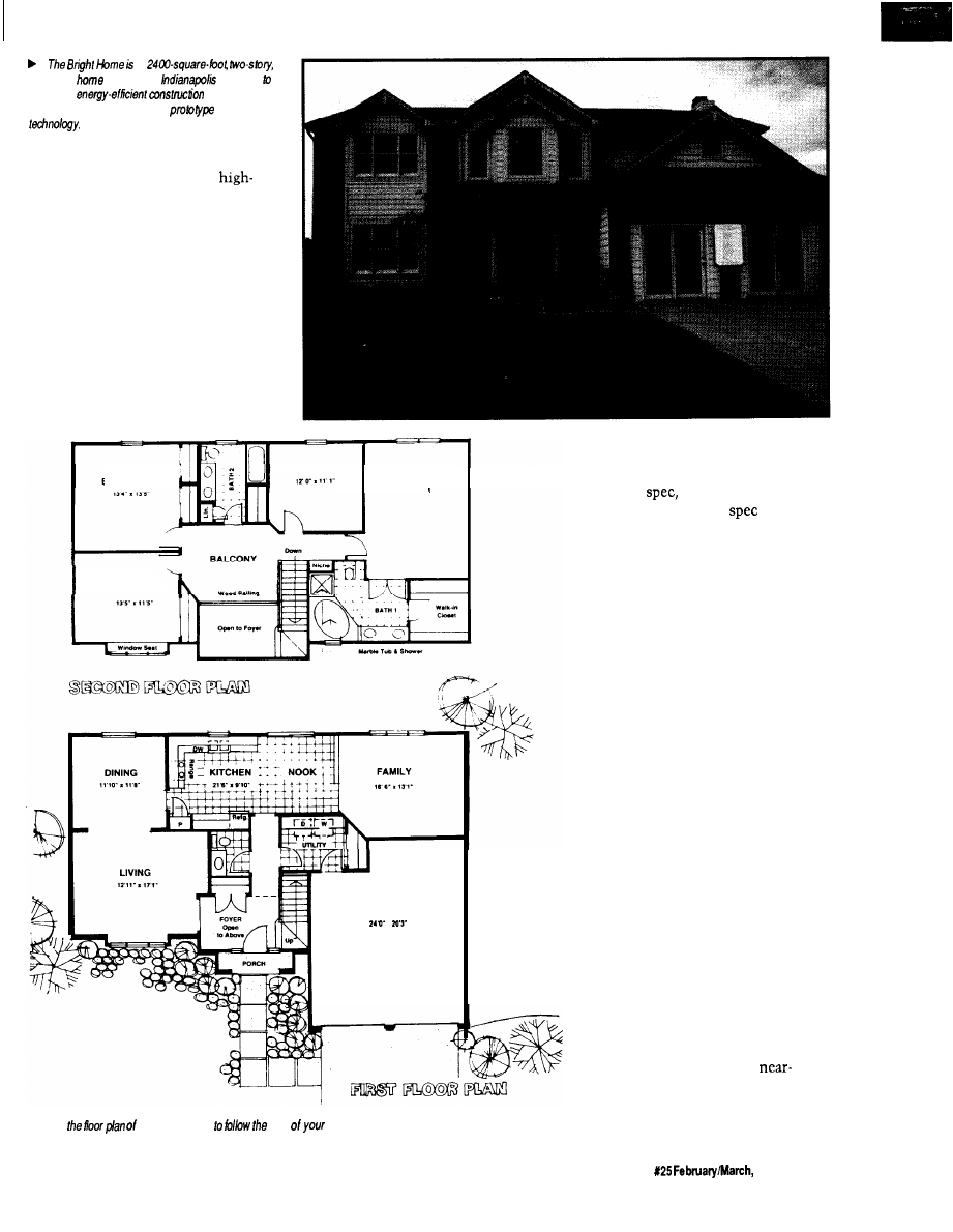
a
traditional
in suburban
designed
showcase
techniques,
high-efficiency appliances, and
CEBus
We are led into the living room
while she explains the use of
efficiency halogen and fluorescent
lighting throughout the house. She
also introduces us to the idea that the
home has been fitted with a new
technology called CEBus, which will
revolutionize the way we live in the
future. All of the devices in the house
communicate using one of the CEBus
media, including power line, twisted
pair, coax, and infrared.
(RF wasn’t used by any of the
devices in the house. All of the CEBus
devices were working prototypes
BEDROOM 2
BEDROOM 3
MASTER
BEDROOM
BEDROOM 4
GARAGE
.
A Use
the Bright Home
path
guided tour:
supplied by numerous manufacturers.
Most were based on an older version of
the CEBus
but that’s not surpris-
ing, given how new the
is and
how long it takes to get a prototype
working.)
Next, we’re led into the dining
room where Mrs. Jones shows how
easy it is to automatically bring the
lights up to a preset level, or to dim
them to provide a more romantic
ambiance for those evenings when the
kids are away at Grandma’s, all with
the press of a button or two.
Walking into the kitchen, we are
greeted by more high-efficiency lights
and appliances, but also a television
sitting on the counter with some extra
outlets on the wall behind it. Mrs.
Jones picks up a handheld remote,
points it at a receiver on the wall
above the door, and a menu pops up on
the television screen. She proceeds
into a monologue about how wonder-
ful the future will be where we can
bring up recipes on the screen from
our in-home database, or how we can
check out the local restaurants,
complete with pictures of the interi-
ors, then make reservations for the
evening.
(I found the use of futuristic on-
line services within the context of a
demonstration of current or
future devices to be out of place. The
already confused consumer may look
at the far-future services and attribute
The Computer Applications Journal
15
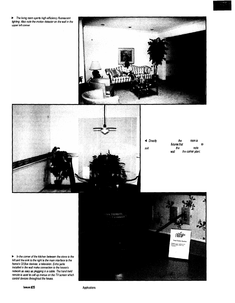
off he living mom, dining
lit by
contemporary halogen
can be dimmed
the desired mood. As in
living room,
the
motion detector on the
above
1 6
February/March, 1992
The Computer
Journal
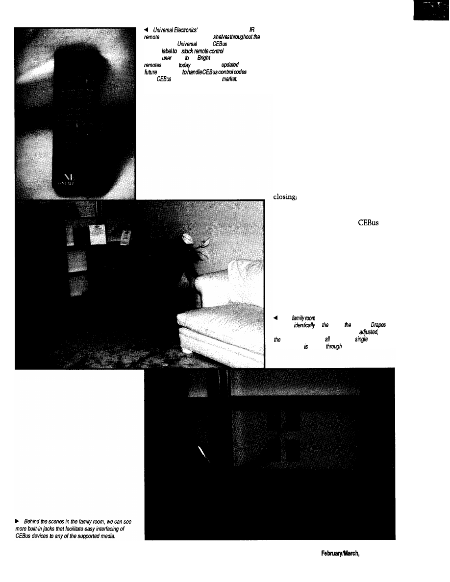
One-For-A/f hand-held
can be bought off store
country today.
added
codes and a
custom
a
and used if to
provide
input the
Home. One-For-All
bought
can be easily
in the
by dealers
once
more
devices start to hit the
everything in the house to also being
fake and in the distant future.)
With background music piped into
the kitchen from overhead speakers,
Mrs. Jones pretends the phone is
ringing and answers it. Much to the
amazement of everyone in the room,
the music cuts out as soon as the
receiver is lifted.
Walking through the breakfast
n o o k i n t o t h e f a m i l y r o o m , r e m o t e
still in hand, Mrs. Jones introduces
U
S
to the home entertainment system. A
complete stereo system sits off to one
side of the room while a large televi-
sion sits in a another corner. Pressing a
single button on her remote, she
activates a series of automated events,
which include the drapes behind us
the stereo, TV, and VCR
coming on; and the movie in the VCR
starting to play. Again, all communica-
tion between devices is via
media. The drapes are controlled over
the power line and are accommodated
by extra outlets installed near the tops
of the windows throughout the house.
TV/VCR communication is over coax,
while communication between the
owner and the system is through the
IR remote.
The
contains another television which
operates
to one in kitchen.
can be closed, the temperature can be
and
VCR can be started by using a
remote
whose signal relayed
the TV.
The Computer Applications Journal
Issue X25
1992
1 7
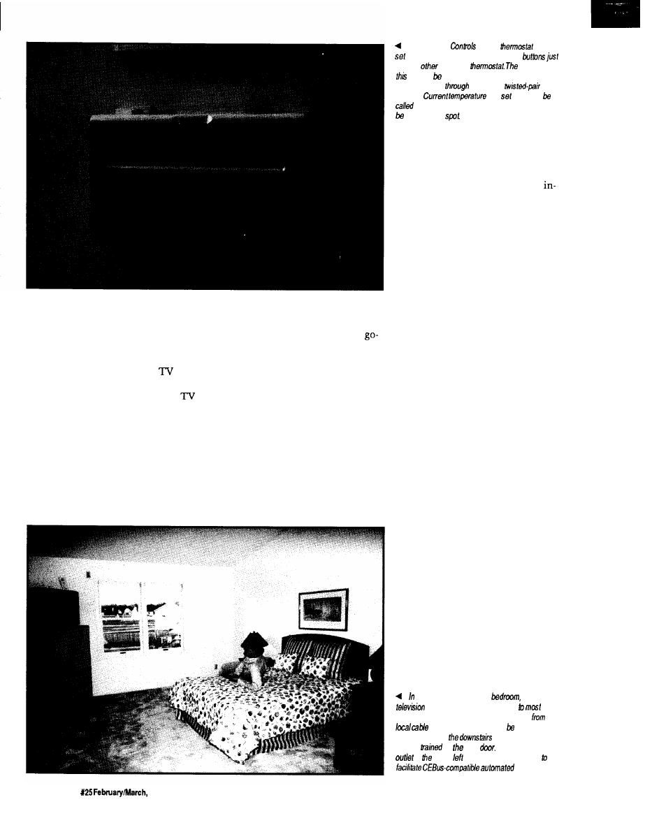
Mrs. Jones next shows how
devices can also be controlled interac-
tively by pressing a button on the
remote to open the drapes again. A
message on the bottom of the
screen reflects the change in status.
She also brings up a display on the
showing the current temperature and
thermostat set point. Changing the set
point is as easy as pressing a few more
buttons. Communication with the
thermostat on the wall in the front
hall is via twisted pair.
Mrs. Jones then picks up the
phone on the end table and calls
upstairs to “Mr. Jones” to see if he is
ready for some company. With the
ahead, the group proceeds upstairs for
more.
ACT 2
We are greeted at the top of the
stairs by Mr. Jones, who also starts
espousing the virtues of the home’s
efficiency and the wonders of CEBus.
We are led into the master bedroom
where, armed with a similar IR
remote, he turns on the TV in the
comer of the room and brings up the
same movie we’d been watching
The Johnson
CEBus
can be
by walking up to if and pressing a few
like any
electronic
difference is
one can set from anywhere
in the house by
communicating
he CEBus
medium.
and
point can
up on any
television screen and adjustments can
made on the
downstairs. He then switches to a
camera mounted in the garage to show
us we can select from multiple video
sources, including both cable and
home generated. With another “here’s
something neat that you’re not likely
to see real soon,” Mr. Jones proceeds to
describe the idea of buying movies
from home and having them sent via
high-speed telephone connections
(presumably ISDN or beyond), so we
get personalized service without
leaving the comforts of home.
Walking down the hall, we come
to Mr. Jones’ home office. Here, we
have everything a good home office
should have, including a computer,
printer, telephone, and fax machine.
The bonus is the extra outlets on the
wall including four power outlets, a
telephone jack, a twisted pair jack, a
pair of coax jacks, and some blanks. (In
a real CEBus implementation, tele-
phones are incorporated into the
twisted pair medium, but in this in-
stallation we still have a separate tele-
phone system.) While in the office, we
get the standard pitch about how eve-
ryone in the future is going to work at
home. I’m sure you’ve heard it before.
Mr. Jones then tells us a “techni-
cian” is down in the basement just
finishing up a few last-minute items,
and perhaps he’d speak to us. A phone
call to the basement confirms that
he’d love to see us, so the group
meanders down to the basement.
ACT 3
Once in the basement, the
technician tells us mostly about the
heating and cooling aspects of the
the second-floor master
yet another
provides the user with access
of the
house. Programming coming into the house
the
television
company may selected for
viewing, as may
VCR or a remote video
camera
on front
Note the additional
AC
lo upper
of the windows, installed
drapes.
18
Issue
1992
The Computer Applications Journal
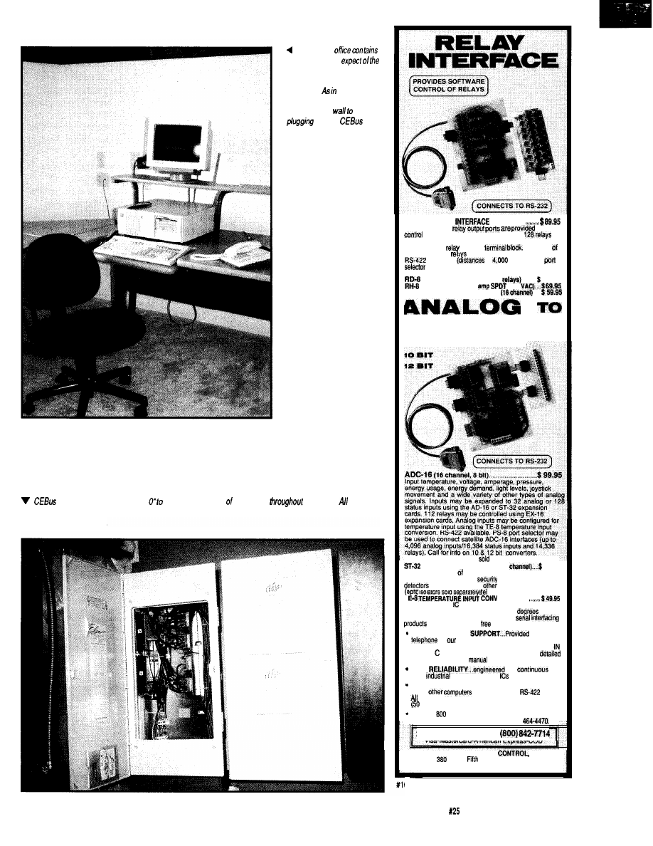
The home
everything you’d
domestic businessman,
including a computer and
telephone. most of the
house,
additional jacks are
installed in tie
make
into the
network a
snap.
tired media require a “Node oversee distribution the signals
the house. the coax
in the Bright Home goes to a common pint in the basement where both external and in-home-generafed video are
combined and redistributed,
AR-16 RELAY
. . . . . . . . . . .
Two 8 channel
far
of up to 16 relays (expandable to
using EX-16 expansion cards). Each relay output port
connects to a
relay cards and
card or
A variety
are stocked. Call for more info.
available
to
feat). PS-8
may be used to control satellite AR-16
interfaces (up to 16,384 relays).
REED RELAY CARD (8
. . . .
49.95
RELAY CARD (10
277
EX-1% RELAY EXPAN. CARD
. .
DIGITAL
8 err
(terminal block and cable
separately)
STATUS EXPAN. CARD (32
79.95
Input on/off status relays. switches, HVAC
equipment, thermostats,
devices, smoke
and thousands of
devices.
T
isolators sold
)
. . . . . . . . .
Includes 8 linear temperature sensors.
Temperature range is minus 78 to 146
F.
TWCH TONE DECODER and other
available. Call for
information packet.
FULL TECHNICAL
over the
by
staff. EACH ORDER INCLUDES A
FREE DISK
WITH PROGRAMMIN
G
EXAMPLES
BASIC. AND ASSEMBLY LANGUAGE. A
technical reference
is also included.
HIGH
for
24
hour
applications. Ail
socketed.
Use with IBM and compatibles, Tandy, Apple and
most
with RS-232 or
ports.
standard baud rates and protocols may be used
to 19,200 baud).
Use our
number to order FREE INFORMATION
PACKET. Tech&al information (614)
24
HOUR ORDER
LINE
Visa-Mastercard-American Express-COD
ELECTRONIC ENERGY
INC.
South
Street, Suite 604
Columbus, Ohio 43215
37
The Computer Applications Journal
Issue
February/March, 1992
19
The
Home
a
make
the house
energy
possible.
always
possible
went
building
house
once
so the
make it easy
study the
used by
providing a
small mock-up
encompasses them. Note, too,
the
wired media
installed the
the house
was
house, which I’ve already briefly gone
into. He also shows us a single panel
that houses all the coax cables from
the various rooms throughout the
house. Within the panel, the cables go
to assorted switch boxes and splitters
and look very impressive. He wouldn’t
open the other two panels or the closet
under the stairs for me. “House
Rules.” [I did manage to get a peek
under the stairs later and saw the
magic running the parts of the house
that had to be faked. While all the
devices in the house were truly
operating over
media, the
demonstration had to be pulled
together quickly, so it was inevitable
some hand waving had to be done. I
certainly don’t take anything away
from the designers for doing so.)
THE DRAMATIC ENDING
After we finish poking around in
the basement, we are ushered into the
garage, which has been made into a
makeshift sales office and showcase
for the home’s construction tech-
niques. Numerous displays are set up
to provide a more in-depth look at
Affordable 8031 Development
Single Board Computers, Assemblers, Compilers,
Simulators, and EPROM Emulators
Control-R Series, Single
and Hardware Development Tools
Two models of Control-R series computers make
prototyping, one of a kind products, or small
production runs easy and economical. Both feature
RS232 compatible serial ports, single 5 volt supply
operation, and direct access to Ports 1 and 3 of the 8031.
Additional features are as follows:
Control-C 8031 Cross-Compiler $200.00
Model 1 $49.95
The Control-C 8031 cross-compiler is a full featured K&R style C
development system available at an affordable price. Optimized
for embedded system use, it will
code for any
8051 based system including designs using only the 128 bytes of
internal
Package includes compiler, pre-processor,
assembler, simulator, printed documentation and complete library
source code. Requires IBM PC or compatible.
360K disk.
Fully populated board with I/O header for Ports 1 and
3, serial port, and
EPROM socket. 3.0” x 4.0”
256
$189.95
Control-R Model 2 $79.95
Same features as the Control-R 1 plus 8K of SRAM and
expansion bus with data, address, RST,
WR,
RD, PSEN, ALE and
3.5” x 4.5”
An EPROM emulator lets you avoid “Burn and Test” development
cycles. In circuit emulation of
series EPROMs. ABS
Plastic case. Assembled or compiled code is downloaded directly to
the target hardware.
Cottage
Suite 151, 10271 South 1300
East
Sandy, Utah 84094
VISA/MC. COD. Call to Order: (801)
2875
February/March, 1992
The
Applications Journal
what we just saw on the tour. As you’d
expect, officials are available to answer
questions.
The Bright Home was not a place
to pick up technical details (and,
indeed, it wasn’t the home’s intention
to provide them). I took my initial tour
with a builder who was interested in
the ideas, but wasn’t very technical.
He did have questions that the very
nontechnical actors couldn’t answer,
though, so I ended up doing as much
narration on the tour as the tour guide.
Later in the week, I went through
again with members of the
committee who were in town for their
regular meeting. Many of them wore
expressions of amusement at the
nontechnical presentation and over-
simplified details, but they were also
delighted that the word is starting to
get out to the common consumer.
Overall, the Bright Home was an
excellent demonstration of what we
can expect to begin seeing on store
shelves within the next few years. It
exposed Joe Consumer to concepts he
thought only the rich could afford, and
started the all-important consumer
education that will be necessary if
home automation is to be accepted by
the masses.
CURTAIN CALL
The
aspects of the Bright
Home were pulled together by mem-
bers of The
Project,
administered by Mike Coffey and his
crew at Hometronics Inc. Members of
the
Project contributing
equipment to the home include Draper
Shade and Screen, Integrated Commu-
nication Systems, Johnson Controls,
Manufacturing, Panasonic,
Somfy Systems, Sony, Square-D,
Thomson/RCA Consumer Electronics,
Universal Electronics, and Tenex
Computer Express. For more informa-
tion about the
Project,
contact Hometronics at 4405 Massa-
chusetts Ave., Indianapolis, IN 46218,
(3 17) 54.56239, fax (317) 545-6237.
401 Very Useful
402 Moderately Useful
403 Not Useful
Quality
P.O. Box 490, R o c k &
U.S., call
i
n
n
n
Rental And 1 O-Day Trials Available
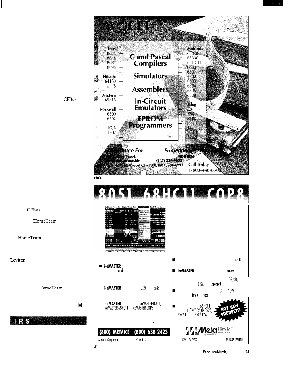
delivers productivity: easy to leom,
easy to use
fast!
Hyperlinked On-line help guides you through the
emulation process.
is FAST! The 11
baud
link
keeps typical download times to under 3 seconds using o
standard COMM
port!
is Versotile:
and
support most
fomily derivatives.
Call today for FREE DEMO DISK! . . .
Coll today to ask about FREE 8051 Macro
Assembler!
ice/MASTER’”
Your Window
To Emulation
Productivity
Flexible user interface: you con completely
ure the windows for size, content, location ond color.
is convenient! It connects
to your
PC, requires no disassembly, nor does it toke up any
expansion slots. It works on any PC (DOS or
Micro Channel or
Even
Supports
source level debug and
and
source level
4K
buffer with advanced
searching ond filtering capabilities.
New Products!
A, D, E,
5Aand
PO. Box 1329
A
Z
85244-l 329 Phone: (602)
(602) 926-l 198 TELEX:
10
The Computer Applications Journal
Issue125
1992

Home
Control
System II
Steve Ciarcia
Even with a sweater
on under the heavy coat
I could feel the cold blast of wind.
Being in the middle of a clump of pine
trees offered little additional protec-
tion. Instead, I felt like I was being
flagellated by hundreds of little green
whips in unison. The calendar might
have said fall, but the ear lobes
peeking out from under my hat were
screaming winter, winter.
It was really my own fault, of
course. I generally try to schedule
excavation in a more opportune
climate, but this project had to be
finished if I want to get it in the next
issue of
Circuit Cellar INK.
Why did it
seem genius and the weather were
rarely ever in sync on these projects.
When we decided to design a new
more powerful network-based home
control system (HCS), the weather
didn’t seem to be of particular impor-
tance. As I started actually installing
it, however, the revelation that many
new sensors and control outputs could
be accommodated prompted the chal-
lenge for immediate installation. Of
course, the inevitable program exercis-
ing all these sensors and controls
would be left to the brilliance or mad-
ness of the operator. That and cabin
fever during the Connecticut winter.
When I placed my foot on the
shovel to dig a hole for the new
infrared perimeter sensor post I felt
significant resistance. Finding more
rock than dirt under the shovel would
hardly be a new disclosure. Would this
go from being a relatively simple post
hole digging operation to a major
excavation? Would I have to drag out
the backhoe for one crummy post?
There were only so many places I
could put these line-of-sight sensors
after all.
I shrugged my shoulders and
pulled my jacket collar up to better
protect my neck from the wind.
Presuming that tough dirt needed
tougher technique, I jumped
weight on the shovel with both feet.
The realization that one inch below
the surface was solid rock came too
late as I balanced precariously on the
point of the shovel. Then, falling
backwards, I instinctively extended a
foot to break the fall. But, as we all
learned at an age when our bodies were
more flexible, wet pine needles have
little friction. With a very audible thud
I impacted the ground in a sitting
position. Ugh!
Any sane person would have been
cussing up a storm under the same
conditions but I actually sat there
laughing. It was deja vu!
I’ve been here before!
Sitting in the mud triggered a
flashback to my last house when I also
found myself sitting in the mud
amongst the pines. Much too coinci-
dentally, it too dealt with my security
and home control system.
“Merrill, you gotta help me!”
The feeling of panic was coming
over me as I beat on Merrill’s back
door. I needed help, and Merrill was
the only person I could trust, and the
only person who would understand I
wasn’t crazy. As I knocked on the
door, I glanced over both of my
shoulders to make sure no one else
was around.
“Merrill, you gotta help me!”
I stood next to the door in a
shadow that the moonlight failed to
illuminate. It was a cool spring
evening. While the stars shown
brilliantly in their quiet elegance, I
couldn’t help but fear that this would
be the last quiet moment of the
evening if I failed.
“Steve? What are you trying to do?
Can’t you just ring the bell and wait 30
seconds like everyone else?”
Merrill wasn’t really mad, just
startled at my wild-eyed look and
disheveled appearance. I often visited
him but usually announced myself by
22
Issue
February/March, 1992
The Computer Applications Journal
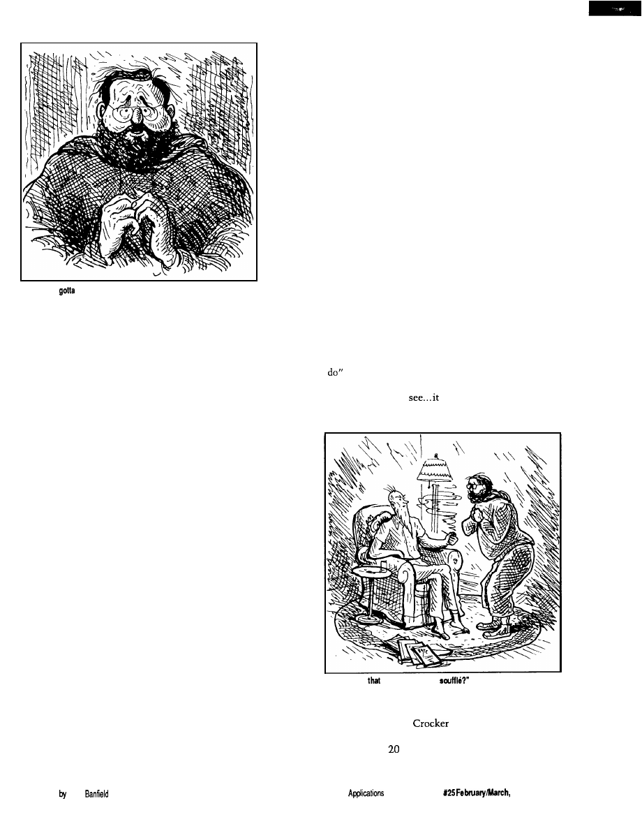
“Merrill, you
help me!”
some means other than beating down
his back door. He waited a few
seconds. Then he realized that this
wasn’t a social call and changed his
tone to one of concern.
“What’s wrong? You look terrible.”
“I locked myself out!”
For any other person in the world,
that would not be a catastrophic
occurrence. In fact, the words sounded
a bit absurd as I said them. I only
hoped that Merrill valued our friend-
ship enough to listen to me.
“You locked yourself out? Didn’t
you once give me a key to hold just in
case this ever happened?” Merrill was
becoming increasingly curious as to
why I should be so distraught. I should
have known he had a key.
I nervously glanced at my watch
and answered. “That was when one
needed a key to get in my house.”
Such a statement obviously would lead
to all kinds of conjectures, but I didn’t
have time to explain.
“What do you mean, no key? How
do you get into your house? Whistle?”
Merrill seemed a bit disturbed that I
was playing guessing games.
“I don’t use a key anymore. I use a
digital code. I really don’t have time to
explain. Please, just put on some dark
clothes and help me.”
His help-thy-neighbor attitude
took five giant steps back when I
mentioned the necessity for dark
clothes. Glancing at my watch once
Illustrations Elliot
again to see how much
time we had left, I
determined that a
portion of it had to be
allocated for explana-
tion. I stepped into the
doorway and moved
past Merrill.
“You see, Merrill,
I’ve locked myself out
of the house, and I have
a souffle in the oven.”
Merrill looked at
me like I was some
kind of nut. He walked
over to the kitchen sink
and opened the cabinet
doors beneath it,
revealing a toolbox.
“Look, we’ll zip over
and pull the hinges on
“Merrill, my house doesn’t use a
house key anymore because it has a
computerized environmental and
security control system!”
He puffed on the pipe and inter-
jected. “Fair enough. But what’s that
got to do with the souffle?”
“This isn’t just any home-control
and security system. I designed it! An
advanced sensor system tied directly
into my computer makes it about the
most sophisticated home burglar alarm
in the world. I got thinking one night
that I needed a burglar alarm. Since
practically all the lights and appliances
were already connected to the control
system, I just extended its capability a
little. But I got a little carried away on
the engineering, and I’m not sure I can
get in without setting it off.”
he and I had spoken lately, it had
Merrill was amused. Every time
one of the doors. It’s a cinch.”
Before he could pass me any tools,
I interrupted him. “Merrill, it’s not
that easy. You don’t understand. Let
me explain.”
something to do with computers. He
no longer thought I was completely
crazy, just a little. There was still that
one burning question. “What has that
got to do with the souffle?”
The expression “Please
was
painted all over his face and needed no
verbalization. As he sat down in the
overstuffed chair, he extended and
crossed his legs on the
footstool and stroked
his gray beard ner-
vously. The little bit of
fuzz on the top of his
balding head seemed to
bristle like a cat. To
further the impression
that he was ready for a
real fish story, he took
out a briar pipe from his
pocket and non-
chalantly started to
clean it. Between the
sounds of tapping the
pipe on the ashtray and
blowing through the
stem to clear it, he
extended his hand
toward me and said,
“There’s a souffle in the oven, and
let’s
should be done in 30
minutes. But the oven timer only
“Do begin, please.”
The delay was
“But
what’s
got to do with the
excruciating. It was critical to act
buzzes, it doesn’t shut the oven off. I
soon. The souffle was irrelevant. It was
know you’re only an engineer and not
the chain of events that could be
Betty
but even you can guess
accidentally touched off that I was
that it wouldn’t be more than another
worried about. My only hope was to
to 30 minutes before it starts to
talk fast.
bum.”
The Computer
Journal
Issue
1992
23
I spoke rapidly. We were eating up
precious seconds. “When the smoke
from the burning souffle hits the
smoke detectors on my alarm system,
all hell is going to break loose on this
street.”
“Wow! What does it do, call the
police?”
Most people are familiar with the
standard smoke and burglar alarms
that automatically dial the fire
department. While the end result was
the same, my method was quite
different. The sophistication of my
home-control computer was un-
matched by anything that commercial
companies had to offer. That, in
combination with the mind of your
average, everyday mad scientist, can
produce startling results.
“Well,” I started rather sheepishly.
It isn’t often one has to explain the
limits of his paranoia. “It isn’t every
day you have a fire in your house.
When you do, you want action fast so
you can reduce the damage and get
people out in time. This system is
predicated on everyone acting fast.
When a fire or smoke is detected, it
first sets off the alarm horns mounted
outside next to the garage. I’ve never
tried them, but they’re war surplus
raid sirens.
“Mathematically, the sound level
ought to be high enough to break
about half the windows on the street.
“Mathematically...”
Mrs. Picker, who lives directly across
from my house, will probably have her
whole house moved back about two
feet when they go off.
“Secondly, there are four xenon
strobe aircraft-landing lights mounted
on the corners of the house that will
start flashing with about 2 million
candlepower each. That was just in
case the fire trucks had trouble finding
the house.
“Then come the automatic
telephone calls out on the three
telephone lines. Remember, Merrill,
my computer has a voice synthesizer,
so I don’t need a tape recorder. It
definitely doesn’t sound like a record-
ing, so it should prompt immediate
action. The first call is to the fire
department. It also is simultaneously
transmitted on CB channel 9. Then a
whole bunch more. The end result is
more cars and trucks than we can fit
on this street.”
The pipe in Merrill’s mouth
drooped lower and lower as I conveyed
the consequences of my alarm going
off. It was hanging down to his chin
when he muttered, “Why don’t you
add me to the list of calls in case I
miss the initial shock wave.”
“Don’t worry, Merrill! You’re the
ninth call!” Merrill definitely had a
concerned expression on his face. As I
expanded upon the next step, it turned
to terror.
“Merrill, you gotta
help me break into my
house and shut the
alarm off before the
souffle bums.”
The pipe fell out of
his mouth, and the
ashes formed a line
down the front of his
shirt. He barely noticed
them as he exclaimed,
“Are you crazy! Break
into your own house!”
“Look, Merrill, I
designed that system to
prove I could do it. Now
that I can count the
seconds before I know
it’s going to go off, I
recognize it as pure
overkill. I’ll replace it
later with something
The Computer Applications Journal
Issue
1992
more sane, like six
Doberman
and a minefield. But
right now we have to
stop it! Will you help
me?”
Merrill brushed the
ashes off his lap and
jumped up. “Do I really
need dark clothes?”
“Yes, I’ll explain
later. And wear a dark
sweatshirt with a hood
or something to cover
your head.”
The evening
newspaper fell to the
floor as it was sucked
off the table by the
vacuum created by
I
Merrill as he ran to
“Gee, Steve, why don’t you
a little weight for the
break-in?”
change. I could detect a cold sweat
follow. First, the
would blacken
forming as I checked my watch
and crack. Then, as it shriveled, some
repeatedly. It was only 10 minutes
of the exterior sections would have
since we had first started talking, but
dried enough to be combustible. The
now it was only 20 minutes before the
first whiffs of smoke would go
would be done.
but eventually a billowing cloud
I could picture in my mind the
would spew forth from the oven. When
progression of events that would
it reached the smoke detectors, the
computer would go into action. Our
only hope was to get inside in time to
stop the computer. If we failed, we had
better make sure we were not standing
next to one of those sirens when it
blew. Further thoughts were inter-
rupted as Merrill burst into the room
fully dressed for action.
“I’m ready. Let’s go.”
Merrill looked like a cat burglar.
The solid-black sweatshirt had a hood
that completely covered his balding
head and, while his gray beard still
showed, it aided the camouflage. His
pants were equally dark and skintight.
All reflective surfaces like belt buckles
and key chains were carefully omitted.
Black track shoes completed the
outfit. I only hoped we didn’t have to
do too much running with the rope.
As we jogged up the street toward
my house, Merrill turned and asked,
“You sure you know how to get in!”
The details of the computer alarm
design flashed through my mind. I
knew every wire, every sensor. Yes, I
knew what the components of the
system were, but the computer had far
greater speed than I at analyzing the
Microcomputer.
provide PC functionality in a
88’”
l
CPU clock to 10 MHz
l
Replaces full PC motherboard
l
On-board SCSI Host Adapter
(supports up to 7 devices)
l
Co-processor and BIOS socket
l
Floppy Controller
l
DMA. Bus, DRAM, Keyboard
l
2 RS-232, Parallel. RS-485
controllers
multi-protocol serial port
All Wildcards
are low power
single
volt
operation.
125 Wendell Ave., Weston, Ont.
Fax: (416) 245-6505
l
640Kb User memory
l
LCD controls
CGA, Hercules@‘.
Mono:
(runs LCD Panels)
For information on our
contact our
head
at the number
88 and
are trademarks of
Computer Corp. Hercules is a trademark of Hercules Corp IBM
is a
trademark of IBM
26
Issue
1992
The Computer Applications Journal
data received from them. A pressure
switch activated in the wrong se-
quence, a heat sensor detecting human
presence, any number of things could
activate the alarm. I had let my
inventive genius run “open loop.” The
tiny credit card that now lay on the
coffee table in the living room had
been my only control over the poten-
tial Frankenstein I had created. True, it
would foil a burglar or call the fire
department, but the ends to which I
had gone in devising the system were
aimed more at instant incineration of
any perpetrator than protection of
property.
system. The burglar alarm was equally
devastating.
“Well, there’s a bunch of stuff I’ll
explain as we go along. It’s too compli-
cated to explain in detail. But the end
result is that the computer determines
the location of the perpetrator and
then tries to lock him in the area
where he has been detected and calls
the police.”
“If that’s all, you can explain the
accidental phone call to the police.
They often get false alarms from
automatic dialers.”
To fully answer Merrill’s question
was impossible. I didn’t know whether
I could beat myself at my own game.
“I don’t know, Merrill. I hope so.”
We stopped in front of my house.
Almost magically a floodlight
switched on to illuminate the area
before us. Music could be heard from
inside. A light in one room switched
off, and another turned on. I didn’t
wait for Merrill to ask because I knew
he was curious.
“Wait, you didn’t let me finish.
Then, it sets off all the sirens and
lights, just for good measure. And, oh
yeah, there’s a very loud noise source
inside the house that’s triggered,
which is supposed to temporarily
disable the perpetrator. Then it does
all the same telephone calls, explain-
ing there is a break-in instead of a
fire.”
“Most of the AC outlets in the
house are remote-controlled. The
computer can control almost any light
or appliance in the house, except the
stove. The computer knows that
something or someone is out here
from microwave motion sensors
planted in front of the house. No one
is in the house, but it is simulating
habitation by playing music and
making it appear as though people are
moving from room to room. Just for
good measure, it turned the floodlight
on to tell you that it knows you’re
here too.”
Merrill looked at me in amaze-
ment. The adventurer in him wanted
to go full speed ahead
and tackle the Mount
Everest of electronic
obstacle courses, while
his quiet engineering
instinct suggested that
he go home and check
his medical insurance
first. He shook his head
as he said facetiously,
“Why didn’t you just
use tear gas?”
“Oh, I considered
it. It’s just too hard to
get the smell out of the
Oriental rugs.”
This unexpected
Merrill started toward the front
walk. I grabbed his arm to stop him.
“Forget it. The only way into the
house is through some window that
doesn’t have any sensors attached.
They’re in the back of the house.
Possibly one of the bathroom windows
would be the best to try.”
“Hey, Steve, before I lay my life
on the line to save your souffle, do you
mind telling me what happens if we
set off the burglar alarm while trying
to break in?”
response was too much
for Merrill. As we stood
there in the moonlight,
I could see the sweat
“Bark,” said. “Like this.
Atf!
forming above his brow.
To this point, he had been aiding
an eccentric neighbor. Though it had
taken a long time and not through any
direct explanation, Merrill was ready
to admit that this computer alarm had
to be stopped. There was no animosity
that I had created it, just a realization
of the full consequences of its being.
My reputation had preceded me.
He, too, looked at his watch and
The fire alarm was only part of the
sensed the seconds ticking away. No
longer was he along for the ride. Now
he was a committed participant.
“Let’s go.”
I knelt down next to a sandy area
at the corner of the lot. Merrill looked
over my shoulder. Grabbing a short
stick to draw in the soft soil, I started
to lay out the attack plan. “Here’s the
house, the property line, and the key
obstacles. There’s only one way to
approach the house from the rear and
not be detected. We have to go over
the side-yard fence, along through the
brush to the pine trees behind the
house, then across the back lot. Have
you done any pole-vaulting recently?”
“Pole-vaulting? Are you kidding? I
just about have enough energy to go
from the couch to the refrigerator for
another beer. What are you talking
about?” His eyes opened wide and
projected a common expletive. The
general translation was “Hey man, I
agreed to break in a house with you,
but I ain’t pole-vaulting over no
fence.”
That was the easiest way, but I
had to agree with Merrill. The years in
the Cellar being a mad inventor rather
than a tennis pro had taken their toll. I
wasn’t about to pole-vault over any
fence either.
“We’ve got to find a way over the
fence without actually climbing on it,”
I said. “There are vibration sensors in
the vertical supports that are meant to
The Computer Applications Journal
Issue
1992
27

detect anyone climbing over it. Trip-
ping it won’t set the whole alarm off,
but it will start a timer where the
computer treats perimeter events more
seriously. If during that period the
computer senses too many motion and
vibration inputs, it will treat it as a
threat and react accordingly.” I didn’t
elaborate on the latter.
We stood next to the fence. It was
constructed of heavy wire mesh
attached to metal supports. Trying to
vault over such a fence and missing
would be like putting your body into a
cheese grater. It was only about five
feet high though, so there had to be an
easy way over it.
Merrill looked at the situation. I
could see his engineering
going to work. Pictures of levers,
fulcrums, balances, and pulleys were
flashing through his mind. Walking
over to the tree adjacent to the fence,
he started coiling a length of rope in
one hand. With one mighty swing, he
threw the coil of rope over a
high tree limb hanging directly over
and parallel to the fence. Now the rope
hung down and touched the top of the
fence. “Come here, Steve,“ he said.
I was still a little puzzled, even as
he looped the rope around under my
arms and tied a knot at my chest. Only
when he pulled on the other end and
hoisted me off the ground did I realize
how he intended to get us over the
fence.
“Gee, Steve, why don’t you lose a
little weight for the next break-in?”
I felt like a side of beef hanging on
a rope six feet off the ground. When he
started swinging me from side to side,
I thought I was going to get seasick.
The amplitude of the swing got longer
and longer until the arc carried me
over the fence to the other side. The
realization of what the next part of the
sequence would be came a fraction too
late for me to protest. As the arc
carried me over the fence, Merrill let
go of his end of the rope. Logically, I
should have expected that this was the
only way, but the experience of being
swung on the end of that rope hadn’t
any semblance of logical reasoning on
my part. My far-too-late protest started
something like a “whoop” and con-
cluded with the tonal equivalent of
Tarzan merrily swing-
ing through the jungle
and suddenly missing
the last vine.
The fall was only
six feet, but it felt like a
hundred stories. I
thought that if this was
a sample of things to
come, maybe I should
take my chances with
the alarm. It didn’t help
matters when I landed
sitting down. The
ground was quite moist,
and my clothing sucked
up the water like a
sponge. When I put my
hand down to reorient
my position, I felt the
cold spring mud ooze
“I’d swear that
directed my flight toward the toilet on purpose,
but have no proof.”
between my fingers.
The totality of my situation and the
immediate sensations at hand were
summed up with the single word,
“Yech!
As I turned to check on Merrill, I
caught a glimpse of him sailing
through the air. Rather than be
hoisted, he had secured one end of the
rope and tied large knots in the other
to aid climbing. Once at the six-foot
level, he swung out over the fence as I
had and let go. Even though he came
down feet first, the momentum was
too great for the terrain. It took only a
fraction of a second for two skid marks
to form behind his heels, and Merrill
came crashing down in the same
sitting position next to me. His first
word was “Yech!”
I glanced at my watch and realized
there were only
10
minutes left on the
oven timer. I said, “Come on, Merrill,
we can’t sit here like two idiots.
There’s not much time left. We have
to head for the brush on the right and
then crawl toward the pine trees.”
“Crawl? Why do we have to
crawl?”
“I’ll explain when we get there.
Right now, pull your hood up over
your head like this. Whatever you do,
don’t look at the house as you run past
the brush into the pines, or the
computer will see you.”
“What is this, a science-fiction
movie or something? What do you
mean see us. Merrill’s nervousness
was evident by the shrillness of his
voice. He should have believed me
when I said it was the most sophisti-
cated alarm installed in a home.
“Just that. See that small box on
the corner of the porch roof?” I pointed
to a small black rectangular enclosure
suspended below the corner of the roof
line. About every 10 seconds a small
red light flashed, giving it the appear-
ance of being activated.
“There’s a digital television
camera in that box that scans this
section of the yard between a height of
three and seven feet. When that light
flashes, it starts a scan and looks for
changes in light patterns from one
scan to the next. With our dark
clothes, by running just ahead of the
scan we should go unnoticed.”
The seconds it took while we
watched the blinking light until we
could anticipate the next scan seemed
like an eternity. When the precise
moment came, I yelled, “Head for the
pines. Go!”
Running with both hands in our
pockets to shield our skin from
detection made trying to run at full
speed rather awkward. It was more
like a high-speed waddle than the
statuesque gait of a long-distance
runner. We had five seconds to make it
to the pines before the camera would
start to retrace its path and compare
28
Issue
1992
The Computer Applications Journal

the new image to that of the preceding
scan. It was barely
120
feet, but it took
all our effort to achieve it in time.
As I was about to dive under the
first pine for concealment, I remem-
bered something vitally important. I
crouched under instead. “Merrill,
watch out where you walk. That is
where my dogs.. Oh, I see you just
found out. Sorry about that Merrill.”
Merrill was apparently just
mentally chalking it up on his list of
reasons to strangle me when the
escapade was over-which it wasn’t.
Standing out there in no-man’s_land
was not accomplishing the task.
Pointing to his watch, he said, “We
have five minutes. What’s this about
crawling?”
“Don’t worry about it, just crawl.
Remember, we have to stay below
three feet high. Don’t stand up or
we’re dead. Ready? Go!”
Merrill still didn’t understand why
he was on all fours, crawling toward
my house at ten o’clock at night. Life
used to be so much simpler.
We were neck-and-neck about
halfway across the yard when the
computer spotted us. Two bright
floodlights came on, illuminating the
area where we lay. Merrill, exercising
reflex actions learned from years in the
Marines, instinctively dove into a
prone position, as though he antici-
pated an imminent artillery barrage.
At the same time the lights came on,
the tumultuous roar of many vicious
snarling dogs filled the yard.
Frozen in his position, Merrill
yelled, “What have you got, a pack of
hungry timber wolves in the base-
ment? What do you need an alarm
for?”
“Don’t talk. Just bark!”
“Bark?” Merrill looked at me and
shook his head.
“Bark,” I said. “Like this,
Soon we were both barking and
woofing up a storm. My two
would’ve been proud of us. We kept it
up for about 25 seconds, until the
lights and the ferocious dogs stopped
as miraculously as they had started.
Speaking very softly and not
waiting for questions, I said, “Hey, you
can stop barking. There’s a laser
perimeter intrusion detector in this
comer of the yard. It sensed our
presence below the three-foot level. It
turned on the floodlights and the
recorded sounds of barking dogs to see
what it was or try to scare it off.
“Now, here’s what the computer
is great for. After all that was triggered,
the computer turned on a microphone
to listen out here at the same time.
When it heard us barking the same as
any real dog would do upon hearing
the recording, it shut off the alarm
sequence. You see, Merrill, the
computer thinks we are just a dog that
wandered through the yard and not an
intruder. A real burglar, smart enough
to see the different
sensors and trying to
crawl as we have been
doing, wouldn’t know
enough to bark back at
the computer. Neat,
huh? Now we can finish
crawling to the house. It
won’t bother us again.”
Merrill rolled his
eyes and put his muddy
palm to his sweat-laden
forehead. As
faced as one could be,
all things considered, he
said, “Steve, you’re
crazy.”
Not wishing to
argue, since time was
running out, I merely
responded, “Genius is
Mm. Picker
first. We encountered no land mines,
bear traps, or quicksand. We finally
found ourselves resting against the
house just below the bathroom
window. Reaching the next objective
was not as bad as the preceding events.
The window lock was easily pried
open with a pinch bar. I warned
Merrill not to make any noise once he
was inside the house. Then I hoisted
him up to the window. Grabbing the
top of the window frame for support,
he lifted himself off my shoulders and
knelt on the window ledge. Next,
trying to be as graceful as he could in
such an awkward position, Merrill
swung his body around so that he now
never appreciated until
it’s too late.”
“Steve, tell me why I’m going
through all this. What do you have in
your house that is so valuable that you
installed a system designed to counter
an invasion?”
“Well, if I really think about it, I
guess the computer control system and
all the alarm sensors are probably
worth the most.”
Merrill didn’t know how to
respond to that information. We
computer hackers design things
sometimes just for the challenge.
Unfortunately, this particular chal-
lenge was getting out of hand, and
time was very short.
The remaining distance across the
lawn was far less wasteful than the
sat on the sill, with the trunk of his
body hanging outside the window and
his legs projecting inside. Once in that
position, it was easy to swing into the
bathroom and land squarely on the
floor.
In a gymnasium, Merrill would
have executed it perfectly. A small
bathroom was quite another story.
One foot came down squarely on the
carpeted floor, as it should have. The
other foot came down squarely into
the open toilet, as it shouldn’t have.
Remembering that I had warned of
excessive noise, he cussed very quietly
as he extracted his foot from the toilet.
As he leaned out the window to
pull me up, he said “Hey, Steve, I hear
some kind of buzzer in the house.”
30
Issue X25 February/March, 1992
The Computer Applications Journal
I quickly glanced at my watch and
responded, “That’s the oven timer. It’s
running a little faster than I thought.
Now the souffle is overcooking. Help
me up. We haven’t got much time.”
Merrill leaned out the window and
grabbed the shoulders of my sweatshirt
as I jumped up to the window ledge.
My entrance was far less graceful than
his. I had no alternative but to go
through the window head first. I’d
swear that Merrill directed my flight
toward the toilet on purpose, but I
have no proof. At the last instant, I
was able to extend an arm and apply a
force opposite to that of my trajectory.
The result was a dull, rolling thud on
the bathroom floor.
Our totally disheveled appear-
ances lent no levity to the situation.
But we were inside the house, and the
stove was just 20 feet away. If we
could get to the souffle in time to stop
it from burning, we would have all the
time in the world to shut off the rest of
the alarm. “Merrill, don’t say anything
louder than a whisper. There are
planted around the house, and the
computer is listening for loud noises.”
I extended a forefinger against my lips
to dramatize what I had said.
“Steve, I just saw something
outside. Outside near the fence in the
backyard!” Merrill was looking out the
window and after a few moments he
excitedly pointed over my shoulder
toward a dining room window, visible
from the bathroom even though it was
on the other side of the house. “There
it is again!”
I jerked around in time to detect
motion from an unknown object.
“What do you think it is!”
Before he had time to answer, a
human form stood for a second in front
of the window. Extending from an arm
was a long, slender object. For a
moment, Merrill and I just stood with
our mouths open watching the
proceedings. The figure turned sud-
denly. The slender object exhibited a
metallic gleam in the moonlight. Then
the figure was gone, as quickly as it
had appeared.
We looked at each other. Our eyes
were wide open as we whispered in
unison. “I think that was a gun!”
“I think we have a real prowler,
Steve. What are we going to do? He has
a gun, too!”
“Don’t ask me! Remember, I’m
stuck here, too.”
“Suppose. Now just suppose he
was able to get by all the alarms and
got into the house. And just further
suppose he fills his pillowcase and is
about to leave when he decides to go
to the bathroom.
us two looking
down the barrel of that gun!”
“Shhh, Merrill. Don’t be an
alarmist. Nobody can get through my
alarm system.”
“Give me a minute or two to fix it, and show you that the sirens really
do go off.”
Simultaneously, as
Merrill spoke them, I
thought of the exact
same words “But we
did!”
The situation
presented a problem.
Should I leave the oven
on and purposely trigger
the
to bring help
and catch the prowler?
Or should we still try to
finish what we had
started and then hope
the perpetrator wasn’t
smart enough to make
it through my alarm?
I looked at my
watch. The souffle had
to have been
overcooking about 10
minutes. The stove
The Computer Applications Journal
1992
t i m e r w a s b u z z i n g
relentlessly in the back-
ground. I sniffed the air.
What had previously
smelled freshly baked now
had the distinct scent of
being overdone. It would
still take a few minutes
before smoke would be
produced that the com-
puter could smell. We
were in a real dilemma.
We were caught between
our protector and the
prowler.
“Steve, look again!”
Merrill pointed toward the
dining room window. “It’s
a woman!”
The figure was in full
moonlight in front of the
window. The features
were easily discernible,
The
old
above and the tight of monitor) surrounded by add-on circuits that are unnecessary with HCS II.
and I recognized the person
no woman. That’s Mrs. Picker from
position we were now in.
ately. The metallic glint previously
across the street.”
“That’s worse than any prowler
thought to be a gun was the
“Is that bad?” Merrill had little
with
10
guns. She probably saw us
steel tip of a walking cane. I grabbed
experience with Mrs. Picker. He could
poking around and thinks we are the
Merrill’s arm tightly and said, “That’s
not fully comprehend the grave
prowlers.”
Cross-Assemblers
from
Simulators
from
Cross-Disassemblers
from
Developer Packages
from $200.00 (a $50.00 Savings)
Make Programming Easy
Our
Macro
Cross-assemblers are easy to use. With powerful conditional
assembly and unlimited include files.
Get It Debugged -- FAST
Don’t
wait
until the hardware is finished.
your software with our
Simulators.
Recover Lost Source!
Our line of disassemblers can help you
re-create the original assembly
language source.
Thousands Of Satisfied Customers Worldwide
has been providing quality solutions for microprocessor
problems since
1985.
Processors
Intel
RCA
Intel 8051
Motorola 6805
Motorola
Motorola
Motorola
WDC
Hitachi 6301
Motorola 6809
MOS Tech 6502
NSC 800
Rockwell
Intel 8080, 85
Zilog
Hitachi
Mot.
Intel 8096, 196kc
N e w
For Information Or To Order Call:
Zilog Z8
Zilog Super 8
All products
require an IBM
PC
or compatible.
716 Thimble Shoals Blvd., Suite E
Newport News,
VA 23606
(804) 873-1947
FAX: (804) 873-2154
BTK52 BASIC-52 TOOLKIT
The
is an intelligent front end for program development on the
MCS BASIC-52 CPU. It reduces 8052 program development time
substantially and can be used with any MCS BASIC-52 based target
system. The BTK52
on any IBM-PC/XT or compatible.
l
Program download from PC host to
target
l
Program upload from
to PC
. BASK program renumber utility, with “from, “through, “start,
and “increment”
l
screen program editing
l
Single line editing with automatic error line number detection
l
on-line he/p facility
l
Transparent,
adaptive line compression for full input line
buffer utilization
l
functions accessible
one keystroke from the
terminal emulator
l
$125
BASIC COMPILER
l
compatible with code written for
BASIC-52 interpreter
l
NOW
with integer,
and
bit extensions for code
runs more
times faster than the MSC BASIC-52 interpreter
l
floating point support
l
assembly language option
l
Compile
switch to select 805
l
Includes Binary Technology’s SXA-5 cross-assembler and Hex file
manipulation utility
l
Compatible with any RAM or ROM memory mapping
l
Runs on IBM-PC/XT or compatible
.
$295
603-469-3232
l
FAX 603-469-3530
Binary Technology, Inc.
Street . PO Box 67
NH 03770
32
issue
February/March,
1992
The Computer Applications Journal
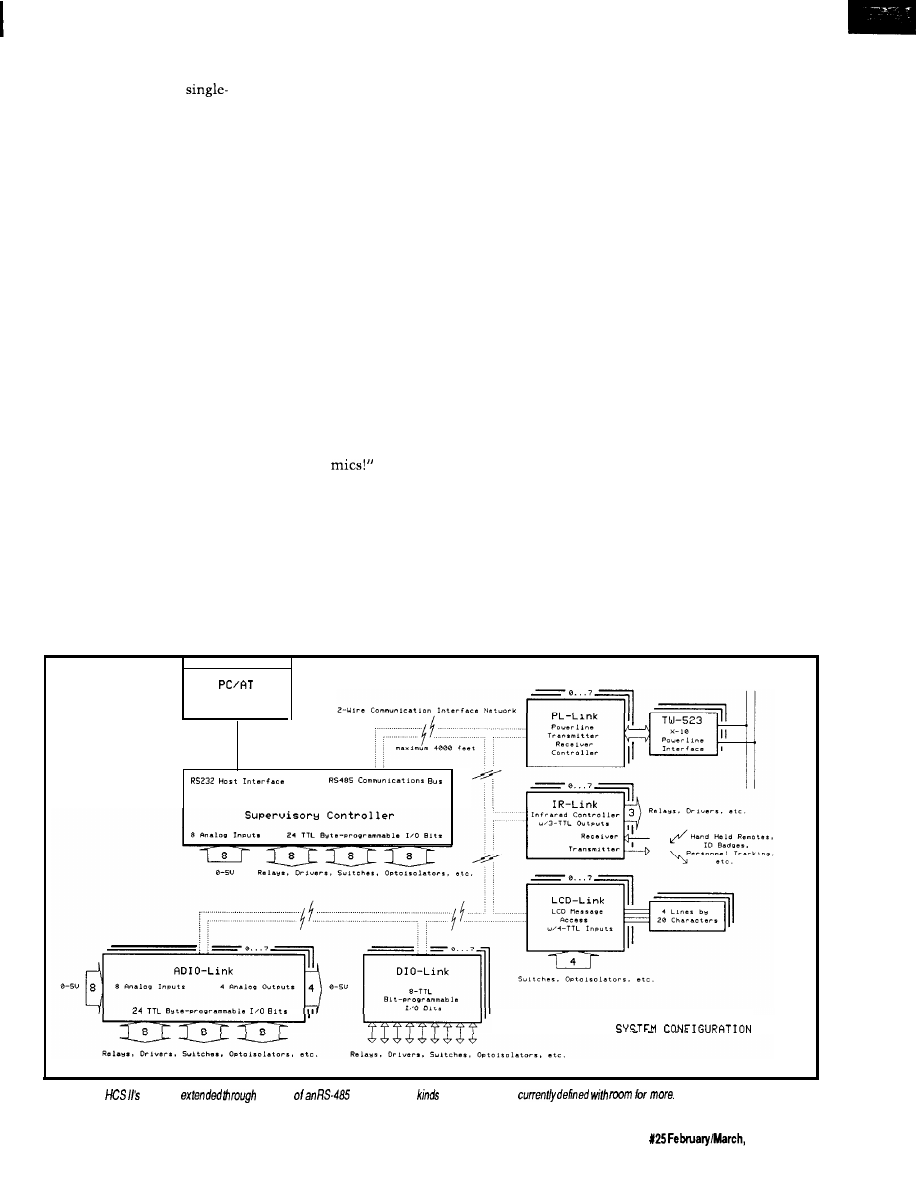
“Boy, that must really take guts to
confront two prowlers
handedly.” Merrill still didn’t under-
“That feisty old lady might be 80,
but I wouldn’t put it past her to climb
stand what I was trying to tell him.
over the fence after us if she discov-
ered the rope. What I’m really worried
about is that while she’s looking for
us, she’ll probably set the alarm off.
When the law arrives, guess who is
wearing the cat-burglar costumes and
covered with mud?”
Merrill looked down at his clothes
and back up at me. His eyes pleaded
with me to act fast. We were in the
worst possible combination of circum-
stances to be caught in. The only
solution was to try to turn off the
system before Mrs. Picker triggered it.
“Let’s go,” I said. “We still have to
turn the oven off.”
Merrill agreed. We had no other
choice. Extra time to shut off the
system was gone. First, we had to get
to the stove. Motioning to Merrill that
he should follow in my exact footsteps
and mimic my every motion, like a
childhood game, we started the ordeal.
“Merrill, see those two holes on
either side of the door molding? Those
are photosensors. The computer can
tell if we pass through the door and in
what direction we are going. Fortu-
At the doorway of the bathroom, I
nately, they are only 18 inches off the
lifted my right leg very high and
extended it out over the other side.
floor.”
Shifting my weight to the now firmly
planted foot outside the bathroom, I
retracted the other leg by reversing the
process. Merrill followed suit. We
stood in the back hallway outside the
bathroom.
“Every doorway we go through,
we will have to follow the same
procedure. Got it?” Merrill nodded
affirmatively as I continued to whis-
per. “Now step over this area and
these other two. There are pressure
switches under the rug that will go off
if you step on them. Try not to make
too much noise jumping. Remember
the
Ordinarily, all these sensors and
switches caused the computer to turn
on lights and direct the stereo system
to the appropriate rooms as I walked
through the house, all in the name of
convenience. Now, however, the
feeling I had was like being in combat.
I was in the middle of a minefield
directing those behind to follow in my
footprints. While the sensation of
stepping on a mine could not be
exactly equaled by my computer, the
heart attack following the first sound
of that air-raid siren could be just as
lethal. We silently high-stepped and
hopscotched our way through the
house until we reached the stove.
As I extended an arm to turn the
oven off, I could see the blackened
souffle through the oven door’s
window. It was very disconcerting to
see a creation of one’s hand and mind
shriveled and destroyed. But the
realization that we were still at the
mercy of another such creation
prompted a fast exit. We had not
gotten to the stove too soon. Inside it
was filled with smoke. While not so
dense as to obscure total view, I dared
not open the oven door. The smell was
of burned baked goods, but it was not
dense enough for the computer to get
excited about-yet.
Our final objective was the cellar,
where the computer was headquar-
tered. It was quicker to go there than
try to find and insert the digital card in
the reset mechanism in the front
hallway. The motion sensors in that
area of the house were not as easily
overcome as the simpler variety that
Master Console
A
AC
Powerline
V
HCS II
C I R C U I T C E L L R R H C S I I
Figure l--The
reach is
the use
network. Five
of
modules
are
The Computer Applications Journal
issue
1992
3 3
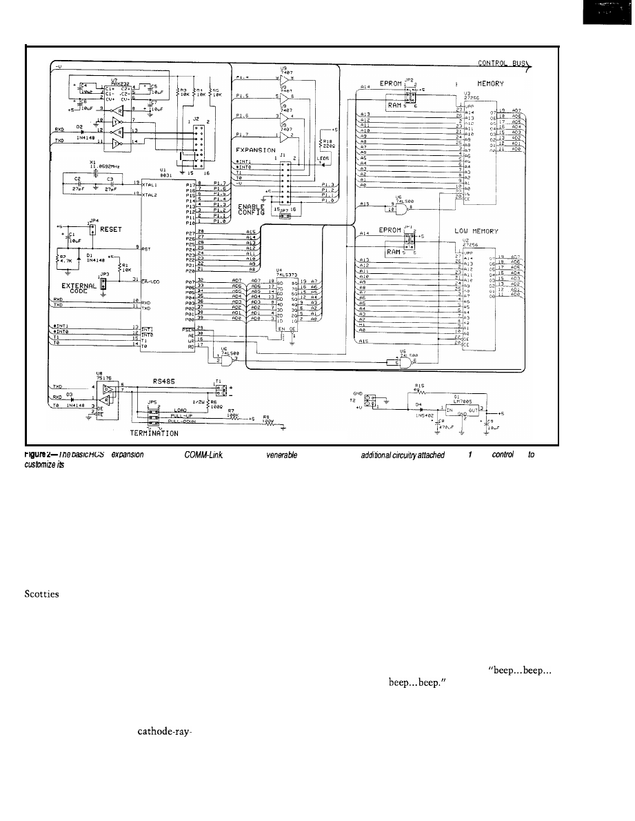
R S - 2 3 2
H I G H
II
module
IS
he
Based on the
8031, each unit has
to Port or the
bus
operation.
we
had thus far defeated. The cellar
door was but five feet and one pressure
switch from the stove. We made it to
this objective as easily as we had the
others. There was no sensor on the
door. I opened it slowly so that the
squeaking of hinges would not reach
an appreciable volume level.
When we opened the door, my two
looked up at us. “No time to
play now, guys,” I said.
I went bounding down the stairs
with Merrill in close pursuit. “When
the alarm is armed, the dogs stay in
the cellar. So there are just a few
sensors down here. We’re home free!”
Merrill and I stood in front of the
computer control system. This
computer did not have the usual panel
full of flashing lights. That was old
hat. The new stuff all had
tube displays. The monitor attached to
the control system displayed a matrix
of control parameters and on/off state.
Peripheral sensors, not directly used to
determine specific alarm conditions
and still experimental, scanned the
grounds like radar and displayed their
activity around an outline of the house
on another monitor. A dot flashed on
the screen next to the outline. It
slowly moved around the periphery of
the house.
“That’s Mrs. Picker,” I pointed
out to Merrill. “The computer knows
she’s out there. It has turned on the
lights, but it will ignore her unless she
goes over the fence into the backyard.
See, she’s moving in that direction
now. I’ll need about three minutes to
enter the disarm commands.”
Merrill looked around the cellar at
all the equipment. Spying a refrigera-
tor, he started to walk toward it. “Hey,
Steve, why can’t you just pull the plug
on the computer?”
“That wouldn’t do anything. In
case of a power failure, the computer
has battery backup and all kinds of
redundancy.”
I started to type in the first abort
code. Merrill, who finally felt relaxed
again, stood at the refrigerator and
said, “Boy, all this work has really
made me thirsty. Do you have any
beer in here?”
He opened the refrigerator door.
The fact that the refrigerator contained
refreshment became immediately
irrelevant. Suddenly a small speaker
next to the computer started to emit a
loud, repetitive sound:
“Merrill! You triggered the alarm!
It’s going to go off in 10 seconds!”
My mind raced with the thoughts
of things that were about to happen.
The computer had sensed an intruder.
Everyone but the National Guard
36
Issue
X25
February/March, 1992
The Computer Applications Journal
would be here in 10 minutes. Large
jetliners approaching the nearly airport
would be distracted by the brilliant
flashing lights and start to circle the
house instead. They would find Merrill
and me in a state of partial rigor mortis
from the loud horns that would now
go off inside the house. Finally, and
most important, there was Mrs.
Picker. If she was standing next to one
of those sirens when it started, it
would be curtains!
Merrill’s eyes bulged with terror.
Internally, he screamed, how could
this be happening? Vocally, he yelled,
“I thought you said that there were
very few sensors down here because of
the dogs! Why did it go off?”
Simple, yet true. We were done
for, but hc still had to know. “Dogs
don’t open refrigerator doors. That’s
why.”
The 10 seconds had almost
elapsed. My final words were, “Hit the
deck! Cover your cars!” That was
exactly what we did. It was a
tiled cement floor, but we dove under
one of my workbenches and covered
our heads with our arms. Almost
immediately, the beeping stopped.
After about 15 seconds I peeked out.
At 30 seconds we got up and walked
over to the computer.
“I don’t understand,” I said. “It
should have gone off. At the end of the
beeping, it should have started the
sirens and lights and everything. I
don’t understand.”
I walked over to the console and
started to list the program. “There
must be a program bug or a loose wire
in the back here someplace. Other-
wise, it would have gone off.” I busily
typed on the keyboard as I spoke,
“Gee, Merrill, that’s a lousy demon-
stration of my talents. I’m a better
programmer than that.
“Merrill, wait a few minutes, and
let me see if I can fix it. Don’t think
this was all a waste of your time. I
want you to know that this thing
really works. Give me a minute or two
to fix it, and I’ll show you that the
sirens really do go off.”
Merrill didn’t wait. He gave me a
fierce glance and took off up the
staircase. I yelled, “Where are you
going? Don’t you believe this will
work?”
Merrill yelled down the stairs. “I’ll
be right back. I’m just going to borrow
Mrs. Picker’s
CONTROL IS CONTROL
The
phrase “Home Control
System” (HCS) means different things
to different people. To the average
nontechnical person it might symbol-
ize the Frankensteinian Machine
depicted in my introduction. I use the
phrase home control in this project for
lack of a better term, but control is
control, whatever the application.
If we purchase a single-board
controller like those sold by many of
the advertisers in Circuit Cellar INK,
we tend not to qualify the application.
Connecting photosensors to the digital
input lines, solenoids to the output
drivers, and writing a program for
sorting materials on a conveyor belt
surely would not be a strange use.
However, program the same
sensors to interrogate a punched ID
DIGITAL DESIGNERS
MINIMIZE YOUR LOGIC
KARNAUGH MAP SOLVER FOR PC’s
Minimum Gates from Your Specs
l
Combinational,
Sequential
l
Mealy Moore State Machines
l
2 to14 Inputs, Any Number Outputs
l
Sum of Products, Product of Sums
l
JK, D, SR, and T Flip Flops
l
Expert Reference and Tutorial
l
30 Day Money Back Guarantee
SAVE 40% :
(P&H)
NOW DOUBLED IN LIBRARY SIZE
AND WINDOWS 3.0
D C / C A D
Integrates Schematic,
Layout Autorouting
This top-rated CAD out-routed the competition in the
CAD Show-down. DC/CAD displayed its power and flexibility
when routing a double-sided board while competing routers
used four to six layers. This non-copy protected package with
surface mount support includes:
l
Multi-strategy 1
parts autoplacer
l
autorouting with rip up retry
l
Thorough annotating design rule checker
l
Full P-way GERBER and DXF support
Optional autoground plane
with
Optional simulation capability
LEASE PROGRAM SITE LICENSE AVAILABLE
DAY MONEY BACK GUARANTEE
1771 State
34, Wall, 07719
(908)
l
(FAX)
The Computer Applications Journal
Issue
February/March, 1992
37
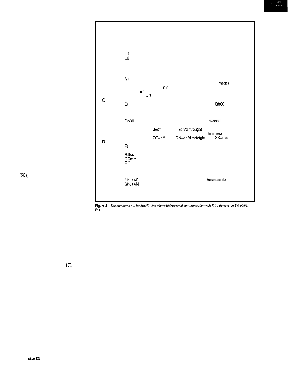
card to control your front door lock
and it appears eccentric.
“Home Control,” like automated
industrial control, is merely the
decision-based execution of control-
lable events that would otherwise have
to be done manually. The singular
factor that determines the size and
architecture of either system is the
quantity of controllable devices and
the number of monitored events.
A home controller is a dedicated
application of what we might view as a
downsized version of the industrial
variety. As the control requirements
expand beyond just lighting control to
include environment, security, and
entertainment electronics, the control
task list can become so complex that
the distinction between industrial and
home controller architecture becomes
less and less.
RATIONAL HOME CONTROL
-MY OPINION
Before I get into my idea for
solving the home control problems of
the
it’s probably best if I take a
minute to explain my personal
philosophy and application of home
control. It’s one thing for someone to
present an opinion, but it’s better
appreciated if you understand the facts
upon which that opinion is rendered.
First of all, I am not a control
fanatic. I look at my HCS as a conve-
nience first and then as an extension
to the security system. I do not look at
it as an independent entity that I
cannot live without (for too long,
anyway] or one that totally compro-
mises security if it fails. And above all,
the HCS controls nothing in a way
that would supersede local
approved appliance controls or would
otherwise jeopardize home owner’s
insurance (I would turn on a circulator
fan through its thermostat/contact
closure input rather than provide
power directly to the fan motor, for
example).
Most HCS owners think of
security as the predominant applica-
tion for their system. Given the
thousands of watts of lights, magnetic
and infrared sensors, and tons of
surveillance equipment I have around,
you aren’t wrong in that assumption
D
Dump program status (debugging use)
E
Show and clear error flags (debugging use)
F
Flush transmitter and receiver ring buffers
Ln
Set logging mode (bit mapped)
L
report current mode
LO
disable (default)
show received X-10 messages
show transmitted X-10 messages
L4
show refresh changes
Nn
Set network/interactive mode
N
report current mode
NO
set interactive mode
network mode (no error messages) (default)
N2
network mode with command echo (no err
P
Report power failure status:
first digit
if power is currently OFF
second digit
if power failed since last P command
Query X-10 module status (see notes)
report all modules for all housecodes as
(module 1 is first on each line)
QS
report all modules for all housecodes in hex
(housecode A, module 16 is first)
report all modules for housecode h:
(module 1 is first)
1
X=not used
Qhmm
report module mm for housecode h:
used
Set refresh period (see notes)
report current period in seconds
Rmm
set period in minutes
set period in seconds
clear refresh buffer, set period in minutes
dump contents of refresh table
RESET Perform power-on reset
S
Send X-10 message (see notes)
Shmmff
send function ff to housecode h module mm
send ALL UNITS OFF command to
h
send ALL LIGHTS ON command to housecode h
Shmmffrr
send function ff to housecode h module mm
function message repeated rr times
(may be strung together: Shmmff,hmmffrr,hmmff)
here either. However, sensing intru-
sion and doing something about it are
different problems. Most local police
don’t like dealing with voice synthe-
sizers, taped messages, or false alarms
from “user installed” security systems.
Furthermore, booby traps, whether
they are computerized or not, are
illegal.
To live in a conventional society,
sometimes you have to do some
“conventional things.” To take
maximum advantage of insurance
discounts, I had a commercial
hardwired fire/security system
installed before the first HCS wire was
strung. I pay a certain fee per month
for constant monitoring [the few times
I have had to greet the police in the
driveway have been for “righteous”
causes). I merely “borrowed” all the
signals from the commercial security
system, and connected them (with lots
of others) through optoisolators so the
HCS could use them too.
I have no interest in pressing
buttons as I enter the shower to
automatically adjust the water
temperature and blow dry myself to a
Vivaldi symphony. I don’t need a voice
synthesized butler to tell me that my
suit was automatically cleaned and
pressed while I slept last night or to
greet people at the front door. I don’t
need a system that keeps an inventory
of the refrigerator and tells me how
many calories I’ve consumed while
reminding me of the consequences.
And above all, I don’t want to interact
with anything that makes it appear
that I’m living in “its” house.
Instead, I want to be able to walk
into rooms without having to use
manual light switches. I want a system
to monitor otherwise independently
controlled activities (like the furnace,
38
February/March, 1992
The Computer Applications Journal
wood stove, water pumps, electricity,
flood/smoke/fire sensors, etc.] and
indicate when these systems are or are
not operating within preset parameters
(stack overtemp, water in the base-
ment, etc.). I want direct control of
entire system through a convenient
remote control (display status, do this
or that, set or reset, etc.) or otherwise
have “it” know of my specific pres-
ence in certain situations.
want it readily apparent to anyone in
the vicinity of the house that “it” is
responsive and sentient and knows
every move they make. [There are
some funny stories about a few of
these visits. To this day the oil
delivery guy won’t come unless I am
home.)
THE TRANSITION FROM OLD
TO NEW
Finally, while a sense of “being
The
original HCS that I designed
controlled” is something I abhor when
seven years ago was a first attempt to
I am present in the house, I want the
bridge the gap between low-cost
opposite to be true when I am not. I
loop home control and closed-loop
industrial control. It was adequate up
to a point but, in retrospect, it didn’t
go far enough.
The old HCS combined X-10
capability with sixteen inputs and
eight outputs. Having inputs allowed
connection of motion detectors, floor
switches, water sensors, and so forth.
The basic concept was to allow control
events to occur as the result of a
monitored input and not just limit
control to turning things on or off at
specific times [e.g., walk into a room
with a motion detector and the light
would go on for a preprogrammed
duration). Walk into the Circuit Cellar
and the terminals and equipment will
automatically turn on.
Unfortunately, this first HCS
didn’t go far enough. It could react to
an input but it could not make
Boolean decisions based on a number
of inputs (IF input 1 is set
input5
is set THEN turn on
or deal
with analog inputs such as tempera-
ture limits. I got around this deficiency
by using a separate computer to make
these decisions and then have that
unit direct the HCS to turn on specific
outputs. But after adding two of these
outboard decision modules, I was both
out of mounting space and HCS
inputs. Oh, what I wouldn’t have given
for another 24 input lines.
The final straw was wiring. To sit
in your easy chair and press the X- 10
button for the floor lamp is one thing.
If it doesn’t go on, you’d press it again,
probably look to make sure it was
plugged in, try it manually, and then
replace either the bulb or the X-10
module.
X- 10 control is accomplished by
transmitting a code through the power
line. It is a very affordable control
medium for some things, but it is
susceptible to false triggering or a
failure to trigger [when the oil burner
is firing in my house, X- 10 communi-
cation is about
Except for
sitting next to a light and seeing that it
did go on, you cannot presume with
100% assurance that the device you
transmitted the code to actually
turned on.
Some control connections must be
closed loop. The loop is closed by
turning on the device, sensing that the
The Computer Applications Journal
issue 125
1992
3 9
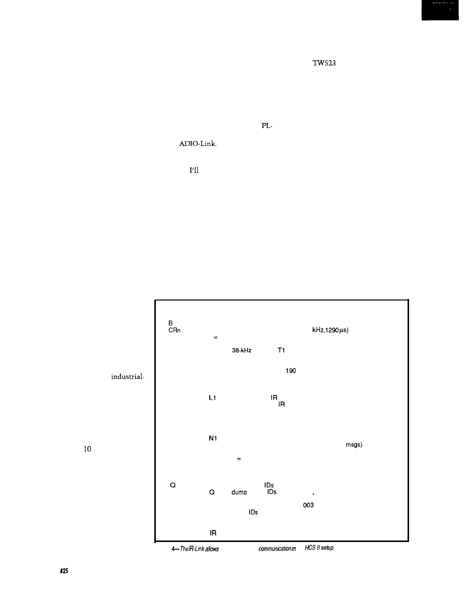
device actually turned on, and setting
an alarm or taking alternative action if
it did not. All this involves directly
wiring sensors and controls to the
HCS.
For obvious reasons, simple house
lighting doesn’t warrant this much
effort but certain systems do. The
pumps and valves in a solar heating
system, a backup battery charger, or an
emergency sump pump are important
enough to control closed loop.
The problem I ran into was that
having a single central control required
all these wires to come back to one
place. That was all right when only the
house was considered, but now I have
the house and five other buildings
(greenhouse, a couple garages, and
storage), and extending direct wired
HCS control (beyond simple X-
10) to
them involves more control wires than
were initially laid in.
HCS II-AN EXPANDABLE
ARCHITECTURE
The solution was to design a new
system from the ground up. Because
my personal application is still
domestic, I refer to the new system as
the Circuit Cellar HCS II for no better
reason. However, after you review the
architecture and see what this entity
actually does, you may agree that HCS
here stands for Humongous Control
Scheme.
First of all, HCS II is not a home
controller. It is an expandable net-
work-based intelligent-node
oriented supervisory control system
that, in its minimal configuration,
performs quite suitably as a home
control system (see Figure
1).
HCS II
incorporates direct digital inputs and
outputs, direct analog inputs and
outputs, real-time or Boolean decision
event triggering, X- transmission or
reception, infrared remote control
transmission and reception, remote
displays as well as a master console,
and has the capability to perform as a
complete badge monitoring and
personal tracking system.
The HCS II system architecture
consists of a central supervisory
controller connected to up to 3 1 other
functional modules (called links) via
an RS-485 serial network. The system
controller and the links can operate
independently and do not need the
system controller or other links to
function, which allows easy testing or
incorporation as intelligent sub-
systems in other control equipment.
Most subsystem links share a common
803
1
controller board (generically
called a COMM-Link) with the I/O
customized for each application.
Currently, we have completed the
Link, IR-Link, LCD-Link, DIO-Link,
and the
A Circuit Cellar
HCS II system need only include those
functions that suit the tasks to be
performed. explain each module
shortly.
A LOT TO TELL
For obvious reasons, designing and
explaining all the hardware and
software of the Circuit Cellar HCS II
has to be a team effort. It is a project
that has been completely designed and
constructed by the Circuit Cellar INK
engineering staff and all of us have
some part to tell.
In this issue I’ve described how
controller design used in the net-
worked subsystems. Ed picks it up
immediately by explaining how to add
the X-10
module and control
software to make the HCS II’s smart
X-
10
PL-Link.
As an essential member of the
team, and the only one who knows
how this event sequence compiler can
ever work, Ken describes the hardware
and software specifics of the Supervi-
sory Controller. Next issue he’ll finish
up with a description of the compiler
software.
Also in the next issue, Ed and I
will describe the IR-Link section and
its uses as an HCS IR remote control
input, as a full-featured badge reader,
and as the essential ingredient in a
complete personnel tracking system.
Finally, Ed finishes out the series
with descriptions of the LCD-Link,
DIO-Link, and ADIO-Link interfaces
and software.
THE HCS II SUPERVISORY
CONTROLLER
The supervisory controller is quite
the HCS II came about and the basic
literally the brains of the system.
All time intervals are in units
of 5.16 ms
C T
D
E
In
Ln
Nn
Pn
On
Set badge response delay (default 40 ticks)
Calibrate remote MC1 46030 bit clock (12.4
n O-3 sets report detail
Calibrate transmitter oscillator
connect
output to
input
Dump program status (debugging use)
Show and clear error flags (debugging use)
Set badge polling interval (default
ticks)
Set logging mode (bit mapped)
L
report current mode
LO
disable (default)
show received messages
L2
show transmitted
messages
L4
show generated polls
Set network/interactive mode
N
report current mode
NO
set interactive mode
network mode (no error messages) (default)
N2
network mode with command echo (no err
Set number of badges to poll (default 0, no polling)
Set output bit 1 high, 0 = low, Default = 1
Oa is bit P7.6
Ob is bit P7.5
Oc is bit P7.4
Query and reset received
all 512
in hex bvtes (about 132 chars)
lb 0 is bit 0 of first byte
Qn
report ID n status in format
= 1
Qn-m
report
n through m in hex bytes
ID n is bit 0 of first byte
RESET Perform power-on reset
Sn
Send ID n (decimal, O-51 1)
Figure
two-way infrared
an
40
Issue
February/March, 1992
The Computer Applications Journal
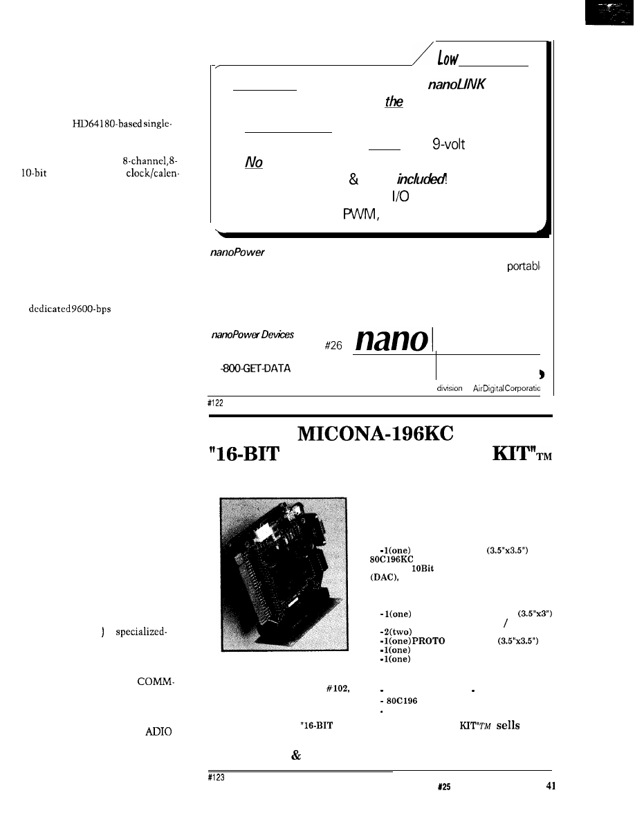
While each link has its own processor,
they all rely upon the supervisory
controller for timing, control com-
mands, and overall system coordina-
tion.
The supervisory controller is a
9.216.MHz
board computer. It has two serial ports;
up to 96K bytes of memory (32K bytes
are battery backed); an
or
ADC; a real-time
dar; and 24 bits of parallel I/O (an
additional 48 bits of parallel I/O can bc
added if required). These parallel I/O
bits can be further conditioned by
externally connecting them to
optoisolators, relays, or drivers. You
may find that the supervisory control-
ler is all you need depending on your
application.
One of the serial ports performs as
a
serial RS-485
connection to the various network
links. The wire from this port can be
up to 4000 feet long (as opposed to 50
feet for RS-232). The second port
connects (RS-232) to a PC/AT that
functions as the master console.
Programs running on the master
console allow the user to enter and
store control sequences, which will bc
subsequently compiled and down-
loaded to the supervisory controller’s
nonvolatile memory. The master
console also acts as an on-line real-
time display of all control activity in
the system. When these downloading
or display functions are not required,
the master console can be turned off to
reduce system power consumption.
See page 46 for more on the Supervi-
sory Controller.
COMM-LINK-INSIDE EACH
NETWORK NODE
Besides the Supervisory Control-
ler, the HCS II system consists of a
multitude (0 to 31 of
function network nodes that facilitate
remote data acquisition, closed-loop
control, and display. With the excep-
tion of the ADIO-Link, all
Links consist of the same generic 803 1
computer with only the external
parallel I/O circuitry and operating
software being different (the
has
additional I/O address decoding and
bus buffering).
Power!
If low power is what you need, the
ultra-low-power controller is
solution!
l
70 microwatts in typical data-logging
applications-run for years on a
battery!
l
software drivers to write-a full BIOS is built-in!
l
Macro-assembler editor
l
Full-featured-8 A/D’s, 32
lines, power drivers,
counter/timers,
battery monitor, more!
Devices
specializes
in highly integrated controllers and
components for battery-powered, solar-powered, handheld, and
applications. Fully integrated driver circuitry and BIOS firmware cuts out
most of the work you have to do-truly a complete, cost effective
solution. Custom solutions also available. Call for information today!
3923
E. Thunderbird Road
Power
Phoenix, AZ USA 85028
1
(438-3282)
FAX 602-996-0255
Devices
A
of
Personal Controller
C O M P L E T E D I G I T A L C O N T R O L S O L U T I O N
MICONA- 196KC
offers:
1.
A HARDWARE KIT containing:
CPU MODULE
with
processor (16 MHz), 8 ADC
channels
resolution, 3 PWM outputs
one DMA channel, 6 High-Speed
Output channels, 4 High-Speed Capture
Input channels, 40 Digital I/O ports, one
full duplex RS-232 serial port;
MEMORY MODULE
with 64K Memory space RAM EPROM;
Connectors BUS MODULE
S
;
MODULE
Power Supply and
RS232 Communication Cable.
M I C O N A C O R P O R A T I O N
1885 Surveyor Ave., Bldg.
2.
A SOFTWARE KIT containing:
Simi Valley, Ca 93063, U.S.A.
PC based SYSMON System Monitor;
Machine Language Assembler;
Tel. l-805-522-9444 Fax. l-805-522-9779
User’s Guide and Application Programs.
The MICONA-196KC
PERSONAL CONTROLLER
for:
$245.00
P.O.,
Visa MC accepted. Immediate delivery.
The Computer Applications Journal
Issue
February/March, 1992
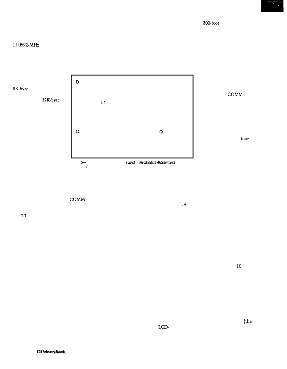
Figure 2 outlines the generic
computer section common to all
network links: Its layout is typical of
many previously demonstrated
803 1 -based controllers
that we have used in other projects,
except this one is configured with
minimal components. It accommo-
dates up to 64K bytes of memory
configured as either RAM,
EPROM, or both. In
general U2 will contain an
RAM (nonvolatile
in some applications) and
U3 will have a
EPROM.
with the PL-Link alone you could
directly control all X- 10 on/off dim/
bright functions from a PC. In addi-
tion, because the PL-Link is “smart,”
it offers the user the added capability
to “listen” to the power line and
record whether any other X- 10 codes
have been transmitted (either manu-
ally or automatically, from this or any
E
Ln
The single serial port
is configured to operate
both RS-232 and RS-485
simultaneously. When
connected to the Supervi-
sory Controller in normal
operation, the connection
is via a twisted pair to the
RS-485. Additional line
balancing and termination
resistors are included.
According to the driver
Nn
Dump program status (debugging use)
Show and clear error flags (debugging use)
Set logging mode (bit mapped)
L report current mode
LO disable (default)
show ANSI decoding sequence
L2 show LCD command processing
Set network/interactive mode
N report current mode
NO set interactive mode
at
the top of a
tower? Use an
ADIO-Link and one twisted-pair wire.
Finally, one minor detail about the
power supply. One exasperating
problem I ran into with the previous
HCS was having to power locally all
the external sensors. More often than
not, the place where I wanted to put
something had no convenient AC
power outlet and 5 volts
was no longer 5 volts if I
ran power wires from
where it was convenient.
While the
Link circuitry runs on 5
volts, the design incorpo-
rates a linear regulator, so
the 5 V can be derived
from a wide-ranging DC
input. The intention is to
promote connecting the
individual links via a
wire cable, rather than just
a two-wire twisted pair,
when local power is
unavailable. Two wires
N 1 nehvork mode (no error messages) (default)
N2 network mode with command echo (no err msgs)
Query buttons, only presses since last are reported
Buttons are bit-mapped in hex byte
Current hardware returns buttons 80, 40, 20. 10 only
RESET
perform power-on reset must be completely spelled out!
S=string
Send string to LCD panel via ANSI decoder
(string continues to end of line)
Figure
The LCD-Link supports a
of
command
s e q u e n c e s addition to debugging commands.
chip manufacturers, this line can be
4000 feet long. In normal operation
only RS-485 is used and the MAX232
(U7) can be removed to reduce power.
The available I/O on the
Link circuit is limited to the Port1 bits
of the processor, interrupt lines, TO,
and
When used as a power-line
interface, these lines connect to the
TW523 X-10 module; when used as an
infrared gateway, these lines connect
to infrared LED driver logic and an IR
receiver; when used as an LCD display,
these lines supply character data to the
LCD. In addition, the COMM-Link PC
boards contain a small prototyping
area to facilitate additional link
designs or modifications to the
existing circuits.
The RS-232 is reserved for local
nonsystem direct testing or use. Each
link has a unique command set and,
for multiple units of the same type, a
unique address. By connecting the link
to the serial port of a terminal or any
PC running a terminal emulation
program, you can directly command
the COMM-Link to do any activity
that it would normally do for the
Supervisory Controller. For example,
other transmitter), and it will auto-
matically “refresh” desired X- 10
modules at a prescribed refresh rate.
The reason for making these links
intelligent is two-fold. First, testing
and problem diagnosis is greatly
enhanced by being able to deal with an
individual unit in a convenient way.
Secondly, while I outlined my reasons
for redesigning the HCS II, that doesn’t
necessarily make it useful for every-
one. I don’t expect the Supervisory
Controller to be adequate for all
process control applications, but these
control subsystems might be all you
need to build an even more grandiose
control scheme.
I expect that some of you will see
the COMM-Link perhaps as the
missing “link” (no pun intended) in
your own personal or professional
control applications. Need an X- 10
gateway for a project? Use a PL-Link.
Need a badge entry system for the file
room or a non-X-lo-related remote
control input to your PC or Mac? Use
an IR-Link. Need an LCD readout a
mile from the computer? Use an
Link. Need to read temperature and
wind direction and set control outputs
supply RS-485 while the
other pair supplies + 12 V
and ground. (Actually, 9-12 V is fine.
Higher voltages requires a larger heat
sink on the regulator.) Of course, using
the regulator is optional, and the board
can be operated (jumper selectable)
on V.
Now that you know the basic
hardware of the links, the functions
and capabilities of each of the network
links is, as Ed would say, “a simple
matter of software.”
PL-LINK-SMART X-10 CONTROL
The
first subsystem you might add
to configure the traditional home
control system would be a PL-Link.
This network node performs X-
activity. While the HCS II accommo-
dates multiple links of the same type,
we presume you would only have one
PL-Link in a system in a normal
configuration.
The hardware consists of a basic
COMM-Link board (Figure 2) with the
X- 10 interface section added. A TW523
power-line interface module is plugged
into the PL-Link’s RJ-11 connector
TW523 plugs into the AC power line).
The software for the PL-Link and the
schematic for the X- 10 interface are
42
issue
1992
The Computer Applications Journal
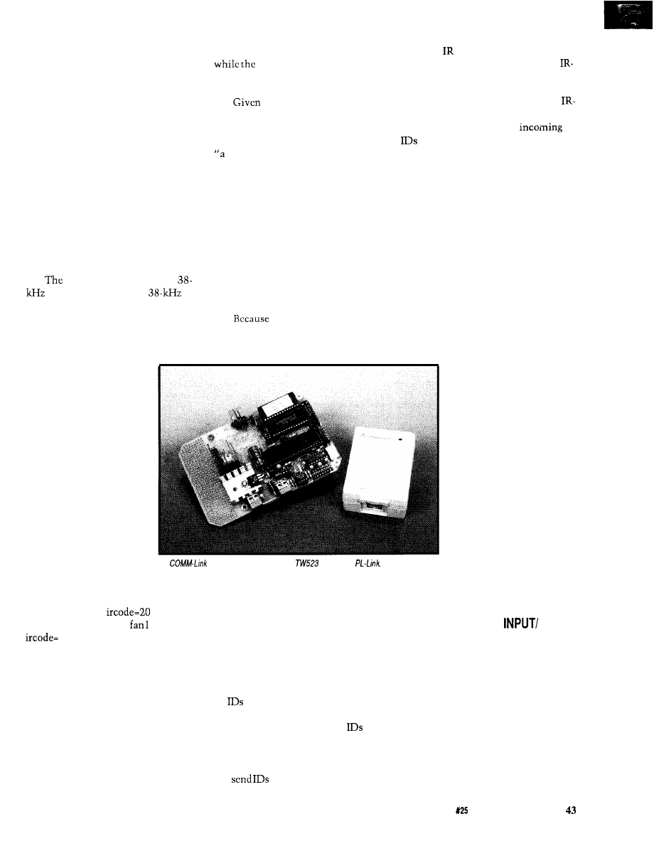
outlined in detail in Ed Nisley’s
“Firmware Furnace” column starting
on page 74 in this issue. A summary of
the PL-Link’s commands are shown in
Figure 3.
IR-LINK-SMART INFRARED
CONTROL AND ID SYSTEM
I don’t want to tell everything
before next issue’s description of the
IR-Link because it will take a lengthy
explanation. Basically, the IR-Link
works via the same RS-485 link as the
other network nodes to send and
receive data. In this instance, the data
consists of wireless infrared transmis-
sions, which are sent and received by
the IR-Link board.
IR-Link board contains a
infrared transmitter, a
infrared receiver, and three output bits
The data format it transmits and
receives is called Manchester coding.
A single transmitted character consists
could direct the lights to slowly dim
electronic barking dog
volume increases (don’t you guys have
all this stuff installed already?].
5 12 interpretable com-
mands, your handheld control could do
quite a bit.
I’m sure you’ve heard the phrase,
funny thing happened on the way to
the office.” Well, this was no excep-
tion. When Ed and I concluded that the
most cost-effective way to provide a
handheld remote for the PL-Link was
to use one of the commercial trainable
units rather than build our own
hardware interface, we created a
dilemma. The only way to train our
remote was if we added an IR LED
transmitter section to the IR-Link and
provided commands to send the codes
as well.
IR-Link has the capability
to both send and receive Manchester
codes, it can serve as the basis for a
of nine bits and represents
one of 5 12 combinations
(multiple characters can be
used to represent signifi-
cantly more combinations
if necessary).
The idea behind the
IR-Link is to use a train-
able handheld IR remote
controller, like the one
you might already be using
with your TV set, and
have it contain 10 or 20 (or
all 5 12) of these codes.
Simply aim the remote at
the PL-Link and that code
would be received by the
A
with some extra parts and a
becomes a
HCS II’s Supervisory
Controller. Within the supervisory
controller’s event repertoire would be
events such as: IF
THEN set
pump ON, light6 OFF,
ON; or, IF
1 THEN all lights ON.
Anything that can be done on an
existing X-10 remote control can be
incorporated within the functions of
the PL-Link. Non-X- 10 activities can
be combined as well. A beeper could
sound, indicating that you have
company in the driveway: without
getting up you could direct the
driveway camera’s video to the TV
you’re watching and turn on a series of
greeting lights at the front door, or you
simple “people tracking” system based
on either active or passive badges (I’ll
detail some badge hardware next
issue). In this context, active badges
send their ID periodically without
prompting, and passive badges respond
to a poll from the tracking system.
Active badges require no special
setup because the IR-Link will record
all
seen by its sensor. Each ID is
cleared after it is reported, so each
Query command returns new
since the last Query. Passive badges
must receive their ID to trigger the
transmission of that ID. The IR-Link
can
(transmitting high
powered throughout a room
requires additional circuitry on the
Link board) at regular intervals and
will record the response; a polled ID is
no different from any other ID. The
Link does not record its own transmis-
sions, so the outgoing and
do not conflict. HCS II can also
accommodate up to eight IR-Link
units on its RS-485 line, so these links
can be placed in separate locations to
broaden the tracking area.
There are many potential uses for
the IR-Link beyond ID system and
remote control receiver. Figure 4
contains a list of the direct commands
for the IR-Link.
LCD-LINK-REMOTE DISPLAY
UNIT
The LCD-Link provides HCS II
with a remote data display capability.
It consists of the same COMM-Link
processor with the firmware pro-
grammed to receive ASCII
strings from the Supervi-
sory Controller and display
them. The LCD is 4 x 20
characters and up to eight
independently addressable
LCD-Links can be con-
nected within an HCS II
system. In addition to the
LCD display, the LCD-Link
has four function buttons
that are read as a four-bit
value (you can interpret
this feature as four function
buttons or sixteen func-
tions defined by four
buttons, depending on how
you write your event
sequence commands). Figure 5 shows a
list of the LCD-Link commands.
DIO-LINK-DIGITAL
OUTPUT INTERFACE
There isn’t a whole lot to say
about the DIO-Link. Like the LCD and
IR units, up to eight can be accommo-
dated within a system. Its hardware is
the COMM-Link circuit again with
the “DIO” referring to the eight bits of
Portl. The eight lines are “bit-pro-
grammable”: each line can be defined
as an input or as an output. However,
because these are direct processor bits
we suggest that the prototyping area
The Computer Applications Journal
Issue
February/March, 1992
on the link board be used to add
custom signal conditioning.
There is also a strobe bit that
indicates when new data is available,
so you can simulate a printer port for
logging or other purposes.
The typical use for this network
link is for remote data collection (what
are the current logic settings of the
relays at the top
of
the elevator shaft)
or closing the control loop without
running sensor wires all the way back
to the controller.
ADIO-LINK-ANALOG AND
DIGITAL INPUT/OUTPUT
INTERFACE
The
is even more of a
good thing. Rather than just eight
digital I/O bits, the
accommodates analog I/O as well.
Each ADIO-Link (there can be as may
as eight in the system) has 24
level parallel bits (byte programmable
as input or output), 8 channels of
or optional
A/D input (O-5 V),
and 4 channels of
D/A output
(O-5
IN CONCLUSION
I’ve tried to explain HCS II in such
a way that perhaps its capabilities and
your control tasks can overlap into a
perfect match. Given the sheer
magnitude of descriptions, I hope I
haven’t overwhelmed you. I think
we’ve succeeded in creating a flexible
architecture that addresses today’s
control requirements and will also
accommodate tomorrow’s Perhaps it
won’t even
be that long before we
demonstrate a
for HCS II.
Stay tuned.
tt This
was adapted from the
chapter called “Computer On Guard”
in “Take My
by
Steve Ciarcia and is reprinted by
permission of Scelbi Computer
Consulting Inc.
Steve Ciazcia is an electronics engi-
neer and computer consultant with
experience in process control, digital
design, and product development.
404
Very Useful
405 Moderately Useful
406 Not Useful
The theme of this issue of The Computer Applications
still have that much time to design everything], as engineers we
is building automation, but there is barely enough space
knew we had to fully define the entire system before we could
to describe the Supervisory Controller and the PL-Link here.
accurately present the first article. HCS II is completely
problem with spreading the design and explanation of such
designed and PC boards are being fabricated at press time. It
a significant topic over a series of articles is the frustration of
seems only reasonable to offer this hardware as it becomes
wanting to use the finished system as soon as the idea is
available for those readers who can’t wait to build it from
presented.
scratch when the articles are presented later this year.
While the HCS II design description is scheduled to be
spread out over six months’ worth of magazines (suggesting we
The following is available from:
Circuit Cellar Kits
4 Park St.
Vernon, CT 06066
Tel: (203) 8752751
Fax: (203) 872-2204
Item 4. DIO-Link Smart Digital I/O Network Interface
PC board and all components including 8031 processor, RAM,
IC
sockets, DIO-Link firmware in EPROM, and user’s manual.
Complete kit
order DIOLINK-
$99.00
Assembled and tested
order
$159.00
Item
5.
Smart 4 x 20 LCD Display Network Interface
Item
HCS II Supervisory Controller
PC board and all components including 803 1 processor, RAM,
HCS II
PC board and all components including HD64180
IC sockets, LCD-Link firmware in EPROM, and user’s manual.
processor, ADC, real-time clock, battery-backed RAM, IC
sockets, multitasking controller firmware in EPROM, HCS
Complete kit
order
LCDLINK- 1 K
$99.00
event compiler on PC diskette, and user’s manual.
x
LCD
order
Complete kit
order HCSIIK- 1
Assembled and tested
order HCSIIA- 1
$199.00
Item 6. ADIO-Link Smart Analog/Digital I/O Network Interface
All components including 8031 processor,
ADC, RAM, 24
bits I/O, IC sockets, ADIO-Link firmware in EPROM, and user’s
2.
PL-Link Smart X-10 Powerline Transmitter/Receiver
manual.
PC board and all components (excluding
including 803 1
processor, RAM, IC sockets, PL-Link firmware in EPROM, and
Complete kit
order
$199.00
user’s manual.
Assembled and tested
order
$299.00
S-bit DAC
upgrade
$35
Complete kit
order PLINK- 1 K
$99.00
Assembled and tested
order PLINK- A
$159.00 Miscellaneous
X-10 power line adapter (not sold separately)
$30.00
modular power supply for link units
Link-Pwr $4.00
Item 3.
IR-Link Smart Infrared Transmitter/Receiver
5-V 0.9-A modular power supply for HCS II
PS-11
$19.00
PC board and all components including 8031 processor, RAM,
IC sockets, infrared LED,
infrared receiver module,
Link firmware in EPROM, and user’s manual.
All items are shipped FOB Vernon, Connecticut and shipping is
extra.
All assembled and tested units come with l-year limited
warranty. A repair service is available to kit builders at an
Complete kit
Assembled and tested
order IRLINK- 1 K
order IRLINK- 1 A
$119.00
hourly charge. HCS II, Link designs, and software are available
$169.00
for commercial license.
44
Issue
February&larch, 1992
The Computer Applications Journal
The Home
Control
System II
Ken Davidson
Supervisory
Controller
engineers, I’m
ure most of you
ave no doubt wit-
nessed the birthing of a
new industry niche. Electronics in
general have become more sophisti-
cated during the last 30 years, and the
dawning of the microprocessor
certainly spawned a giant evolution in
the way control problems are ap-
proached.
Software has
more mature
since the days of punch cards and
FORTRAN. Now entire teams of
programmers are needed to complete a
project that meets the expectations of
today’s computer user in terms of
features, speed, and user interface.
So too are we witnessing the slow
maturation of the home automation
industry. When the Circuit Cellar
Home Control System was first
introduced almost seven years ago,
there was nothing quite like it avail-
able for the price. It allowed you to
turn lights and appliances on and off
based not only on time of day, but also
on direct inputs. A motion detector
could turn on a light in a room, leave
it on for 20 minutes, then turn it off,
all with simple, menu-driven program-
ming.
The times, they are a’
and home control systems are starting
to grow up. The features of the original
HCS, while simple to use, are far too
simple for the growing expectations of
today’s home automatist. Suppose you
want to turn on a light for 20 minutes
based on sensed motion, but not while
you’re trying to sleep. The original
HCS couldn’t handle the task alone. It
required external conditioning of the
motion detector signal to block it
during the times when motion was to
be ignored.
Seeing a need to update the
features of the original HCS, I started
work on the software for such a
system several years ago (as many BBS
users may recall). I brought it to a level
that was comfortable for me and my
living environment, but no further,
which meant limited expandability
and a hostile user interface. When we
decided to get the whole engineering
staff involved, the project took off at
such a pace I’m still reeling. Add a
decent user interface, allow expansion
of the system through a local network,
add support for more types of devices,
the list goes on.
Instead of overwhelming you with
all the details, we’re going to break the
system description into smaller, more
digestible parts (as Steve explains in
his introductory article). In this article,
I cover the “Supervisory Controller,”
which is the brains of the operation.
I’ll start with the hardware, then get
into the complicated stuff: the control
software.
INDEX CARD CONTROL
Figure 1 shows the complete
schematic of the Circuit Cellar HCS II
Supervisory Controller (SC) board. The
SC board measures just 3.5” x (see
Photo 1) and includes up to 96K of
memory, one RS-232 port, one RS-485
port, 32 bits of
I/O, eight chan-
nels of either or IO-bit A/D conver-
sion, and a small amount of EEPROM.
With the addition of a Dallas Semicon-
ductor
we battery-back
32K of the RAM and add a clock/
calendar.
Everyone has a favorite micropro-
cessor. Ed concentrates [often grudg-
ingly) on the 803 1 for its functionality,
inexpensive price, and low power
consumption. Other people I know
swear by Motorola processors to get
the job done. I cut my teeth on the
8080 and have since graduated to the
80 as my processor of choice
(when I have a choice).
The basic
180 isn’t techni-
cally a microcontroller because it has
no provision for on-board memory
(later versions do, however). It does
include a large array of on-board
46
Issue
X25 February/March, 1992
The
Applications Journal
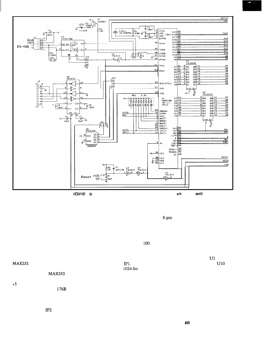
r
Console
RS-232
Figure 1 a--The Supervisory Controller uses an
as brain. Both RS-232 and RS-485 are supported for communicating
the outside
peripherals including two asynchro-
nous serial ports, two timers, two
DMA channels, and a memory
management unit that allows it to
address up to one megabyte of
memory. The instruction set is
identical to that of the 280, with the
addition of a few new instructions
(including an d-bit multiply).
Figure 1 a shows the processor,
serial expansion, and EEPROM. A
(U5) provides a full RS-232
port, which allows connection to the
host computer. The
obviates
the need for power supplies other than
V. A standard RS-485 port is
supported using an SN75
(U4).
With the RS-485 interface, up to 32
devices may be connected to a single
twisted-pair wire having a total length
of up to 4000 feet.
controls
whether the receiver is always en-
abled, or is only enabled when the
transmitter is disabled. When the
receiver is always enabled, we will
receive anything we transmit. This
echo may be good or bad depending on
the application, so it is left an option.
Per the RS-485 specification, a
ohm terminating resistor must be
installed when the board is at the end
of the wire. The resistor is put in the
circuit by installing
The NMC9346
EEPROM
is a synchronous serial device that
communicates over four lines: data
out, data in, serial clock, and chip
select. The HD64 180’s clock serial
port is a near perfect match to the
protocol used with the 9346. A bit of
tricky programming is required to
conform, but in the end it works quite
nicely. We don’t currently use the
EEPROM in the HCS II code, but the
device didn’t take much room,
and we saw a lot of potential in future
revisions, so we put it on the board as
an option.
Figure lb shows the memory, I/O,
and decoding. The SC board contains
three sockets for 32K static memory
devices. Socket U9 must contain a
27256 EPROM and socket
1 must
contain a 62256 RAM. Socket
may be set up for either EPROM or
RAM by setting the pair of jumpers on
JP6.
Twenty-four bits of parallel TTL
I/O are supported on the board using
the venerable 8255 PPI (U12). Ports A
and B are byte programmable for input
or output operation (i.e., all the bits of
each port must be set for the same
The Computer Applications Journal
Issue
February/March, 1992
4 7
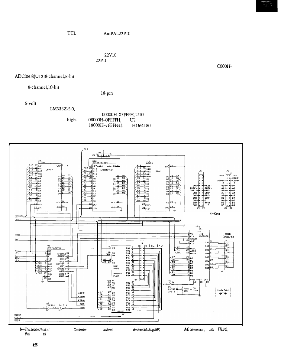
direction]. Port C is nybble program-
mable (bits O-3 may be set indepen-
dent of bits 4-7). Note the raw
bits are brought out to header J4. If you
plan to tie signals to that header, be
sure the signals are properly condi-
tioned or you will end up with a dead
PPI the first time some static electric-
ity courses through the system.
To accommodate analog inputs,
an
A/
D converter is on the board. A Siemens
SDA0810
ADC may
also be plugged into the same socket
for somewhat better resolution. Note
how the
reference is being
generated. We use an
but
it can’t be run-off 5 V. Instead, we steal
a small bit of current from the
voltage output of the MAX232. That
output typically runs between 7 and 10
volts, depending on the current being
drawn by the rest of the chip, and it
works quite nicely.
An
(U8) does all the
grunt work of generating chip selects
for everything on the board. Figure 2
shows the PAL’s equations. The more
popular
may also be used, but
the
is much cheaper. For those
of you who don’t have access to a PAL
programmer, Figure 3 contains a
schematic of the equivalent circuitry.
Note how five discrete chips plus lots
of wires have been shrunk to fit in a
single
chip.
Active-low chip selects are formed
that place the memory devices within
the HD64 180’s memory space (U9
covers
covers
and
1 covers
The
supports separate memory and I/O
spaces, so the rest of the devices on the
board are mapped to the I/O space. The
PAL generates an active-low chip
select for the PPI at I/O address 8000H.
The ADC requires separate active-high
signals to start the conversion and to
read the results. The ADC is mapped
to I/O address 9000H. Also decoded are
three I/O selects that go active in the
ranges of AOOOH-BFFFH,
DFFFH, and EOOOH-FFFFH. These
selects are brought to the expansion
headers to make the decoding on
peripheral boards easier.
I think the only feature I haven’t
mentioned yet is the sleek crimson
human-visual sanity-check feedback
indicator: an LED tied to the transmit
enable line of the RS-485 transceiver.
Nothing like a quick blink a few times
a second to give you that warm fuzzy
feeling of knowing the system is still
alive.
Figure 1
the Supervisory
contains up
static memory
eight channels of
24
of
and a
custom PAL
provides the decoding.
48
Issue
February/March, 1992
The Computer Applications Journal
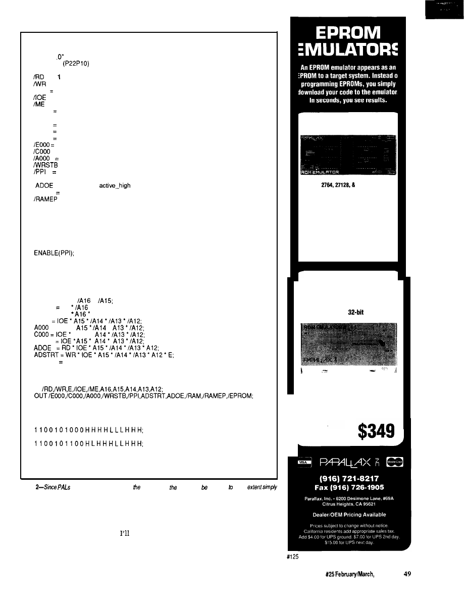
“I/O address and function decoder for the SC processor board”
“Copyright (c) 1991 by Circuit Cellar, Inc.”
“Version 1
DEVICE SC
PIN
= (INPUT combinatorial)
= 2 (INPUT combinatorial)
E
3 (INPUT combinatorial)
= 4 (INPUT combinatorial)
= 5 (INPUT combinatorial)
A l 6
6 (INPUT combinatorial)
A l 5
= 7 (INPUT combinatorial)
A l 4
8 (INPUT combinatorial)
A l 3
9 (INPUT combinatorial)
Al 2
10 (INPUT combinatorial)
14 (OUTPUT active_low combinatorial)
= 15 (OUTPUT active_low combinatorial)
16 (OUTPUT active_low combinatorial)
= 17 (OUTPUT active_low combinatorial)
18 (OUTPUT active_low combinatorial)
ADSTRT = 19 (OUTPUT active-high combinatorial)
= 20 (OUTPUT
combinatorial)
/RAM
21 (OUTPUT active_low combinatorial)
= 22 (OUTPUT active_low combinatorial)
/EPROM = 23 (OUTPUT active_low combinatorial)
“Logic Equation Section”
B E G I N
E N A B L E ( E P R O M ) ;
E N A B L E ( R A M E P ) ;
E N A B L E ( R A M ) ;
ENABLE(AOOO);
E N A B L E ( C O O O ) ;
ENABLE(EOOO);
E N A B L E ( A D O E ) ;
E N A B L E ( A D S T R T ) ;
E N A B L E ( W R S T B ) ;
EPROM = ME
l
l
R A M E P ME
l
A 1 5 ;
RAM = ME
A15;
P P I
= IOE
l
l
A 1 5 ’
EOOO
WRSTB WR
l
E;
END.
TEST-VECTORS
IN
BEGIN
1 1 0 1 0 0 0 0 0 0 H H H H H L L H H L ;
1 1 0 1 0 0 1 0 0 0 H H H H H L L H L H ;
1 1 0 1 0 1 1 0 0 0 H H H H H L L L H H ;
1 1 0 0 1 0 1 0 1 0 H H L H H L L H H H ;
1 1 0 0 1 0 1 1 1 0 L H H H H L L H H H ;
0 1 0 0 1 0 1 0 0 1 H H H H H L H H H H ;
1 0 1 0 1 0 1 0 0 1 H H H L H H L H H H ;
END.
Figure
are programmable devices,
operation of
board can modified some
be reprogramming We part.
YES, MASTER
to worry
about how the status
screen
User interaction with the SC is
is formatted, so we use an IBM PC
through its RS-232 port (which
call
compatible as a host system that
the host port). The SC has enough to
handles such details. Short binary
do [more on that later) without having
messages are exchanged between the
27256 EPROM EMULATOR
Emulates
27255 EPROMs.
Plugs into target EPROM socket and connects
to PC parallel port via telephone cable.
Loads Intel, Motorola, hex, and binary files.
Reset outputs restart target after downloading.
Downloads 32K in 2 sec.
(12 MHz PC AT)
$ 1 9 9
27010 EPROM EMULATOR
Up to 4 units can be daisy-chained to
emulate consecutive EPROMs and to
support 16 and
systems.
Emulates 2754, 27128, 27256, 27512, and
27010 EPROMs.
Plugs into target EPROM socket and connects
to PC parallel port via telephone cable.
Reset outputs restart
target sytem
The Computer Applications Journal
Issue
1992
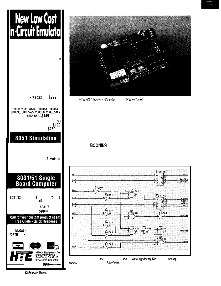
The DrylCE Plus is a modular emulator
designed so you can get maximum
flexibility from your emulator purchase.
The base unit contains all the hardware
necessary to support pods containing
many of the most popular members of
8051 family of embedded control
microprocessors. Buy one base unit, and
select one or all of the pods you need to
do the job at a much reduced cost. You
get the same great functionality found in
our popular DrylCE 8031 emulator plus
real-time Execute-to-Breakpoint,
Line-by-Line Assembler, and much more
And the price is (almost) unbelievable!
(Yes, it works with the Mac, too!)
Base Unit
IF) --
Available Now!
Available Pods:
8751152,
each
16K
Trace Buffer option: Avail. 1st Qtr
Standard 8031 DrylCE -- Still only
Enhanced 8031 DrylCE --
The 8051 SIM software package
speeds the development of 8051
family programs by allowing
execution and debug without a
target system.
The 8051
is a screen oriented, menu
command driven program doubling
as a great learning tool. $99.
A fast and inexpensive way to
implement an embedded controller.
processor, parallel
up
2 RS232 serial ports, volt operation
The development board option allows
simple debugging of
family
programs.
Other products available:
GAL Programmer $199
Card FORTH development card fc
STD Bus $279 (OEM-$199)
566-l
Photo
packs a
onto a
3.5” x 5”
board.
SC
and the host, which converts them
happens when you want to place a
to something pretty for the user to
sensor at the other end of the house, or
look at. The host also is responsible for
you need a user terminal on another
creating the control program for the
floor? RS-485 allows us to make a nice,
SC to execute. However, I’ll cover the
low-speed local-area network to solve
host in more detail in the next issue
the dilemma without requiring you to
because I want to focus this article on
outfit your house with miles of copper.
the SC itself.
A single twisted-pair wire may be run
throughout the house, and up to 32
OUT IN THE
devices may be connected to it.
The SC supports a large number of
The network isn’t intended to
digital inputs and eight analog input
handle large amounts of information,
channels on the board itself. But what
so we keep the speed at a manageable
Figure
3-Using a PAL to do
decoding reduces
chip
equivalent
needed to
the PAL uses five drips and
t126
50
Issue
1992
The Computer Applications Journal
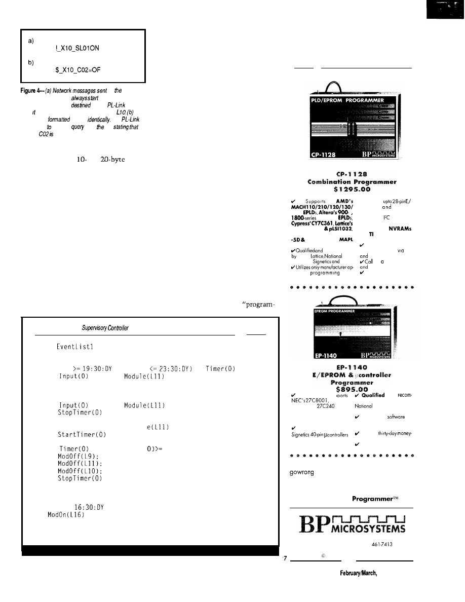
by
Supervisory Controller
with an exclamation
point This message is
for the
and
asks to send an On command to module
T h e
response is
almost
The
IS
responding a status
from
SC
module
off
9600
bps. When you’re passing a
limited number of
or
packets back and forth, the speed at
which the bits travel becomes less
important. Still, there can be a percep-
tible delay between a sensor being
triggered and the resultant action
occurring when communications take
place over the net, so time-critical
sensors should be connected directly
to the SC whenever possible.
The SC is the only device on the
network allowed to initiate communi-
cations. Only one device may have its
driver enabled at any given time, and
it’s very difficult if not impossible to
detect collisions, so strict discipline
must be observed. No network module
may speak unless spoken to (just like
your kids at home, right?).
Network messages use strictly
printable ASCII characters to make
monitoring easier and to allow testing
of network devices using a simple
serial terminal. Figure 4a shows the
basic format of a packet sent by the
SC. It begins with an exclamation
point, followed by a space, the name of
the target device, another space, and
the packet data. All packets are
terminated with a carriage return.
Response packets (shown in Figure 4b)
are nearly the same in format, except
the leading character is a dollar sign.
The address contained in the response
is identical to that in the SC packet so
the SC can verify the correct module is
responding.
I won’t get into the details of how
the individual network modules
operate. Steve and Ed describe the first
one elsewhere in this issue and will be
discussing others in the next two
issues.
A SIMPLE MATTER OF
SOFTWARE
As I mentioned, the original HCS
used a simple menu-driven
Listing l-The
is programmed using a series of ‘event equations.’
Program
BEGIN
IF (Time
AND Time
OR
IF
= ON AND
= OFF THEN
Dim(L1l.lO):
Dim(L9.14)
END;
IF
= ON AND
= ON THEN
END:
IF Input(O) = OFF AND Modu
END;
IF
= ON AND Timer
END
END;
IF Time =
THEN
END
END.
= ON
THEN
1 2 0 0 T H E N
ON THEN
Supports
2 3 0
and MAX
i s p I . 9 1 0 3 2
National Semiconductor’s
-7D
devices and
devices
recommended
AMD,
Semi-
conductor,
others.
p r o v e d
algo-
rithms.
/Supports
E P R O M s
b i p o l a r
P R O M
S
i n c l u d i n g t h e
microwire
de&s.
/Supports
Dallas Semi-
c o n d u c t o r
and
DSP320, Micro-
chip PIC
microcontrollers.
lifetime
FREE software
updates available
BBS
US Mail.
for
DEMO
d i s k
literature pack.
Made in the USA
a n d
The EP-I 140 supports
E - M b i t
mended by Intel, Signetics,
EPROM, all
I-Mbit
Semiconductor, and
1 6 b i t E P R O M s , F L A S H o t h e r s
EPROMs, NVRAMs and all
lifetime
FREE
up
microwire EPROMs.
dates available via BBS and
A l l I n t e l , A M D , a n d
US Mail.
Risk-free
supported directly.
back guarantee.
Made in the USA
With lifetime
FREE
software updates, you can’t
and BP Microsystems offers a thirty-day
money-back guarantee to ensure product satis-
faction. Remember, BP Microsystems is...
The Engineer’s
10681 Haddington
l
Houston, TX 77043.3239
(713) 461.9430
l
FAX (713)
1991 BP Microsystems, Inc.
The Computer Applications Journal
issue X25
1992
51
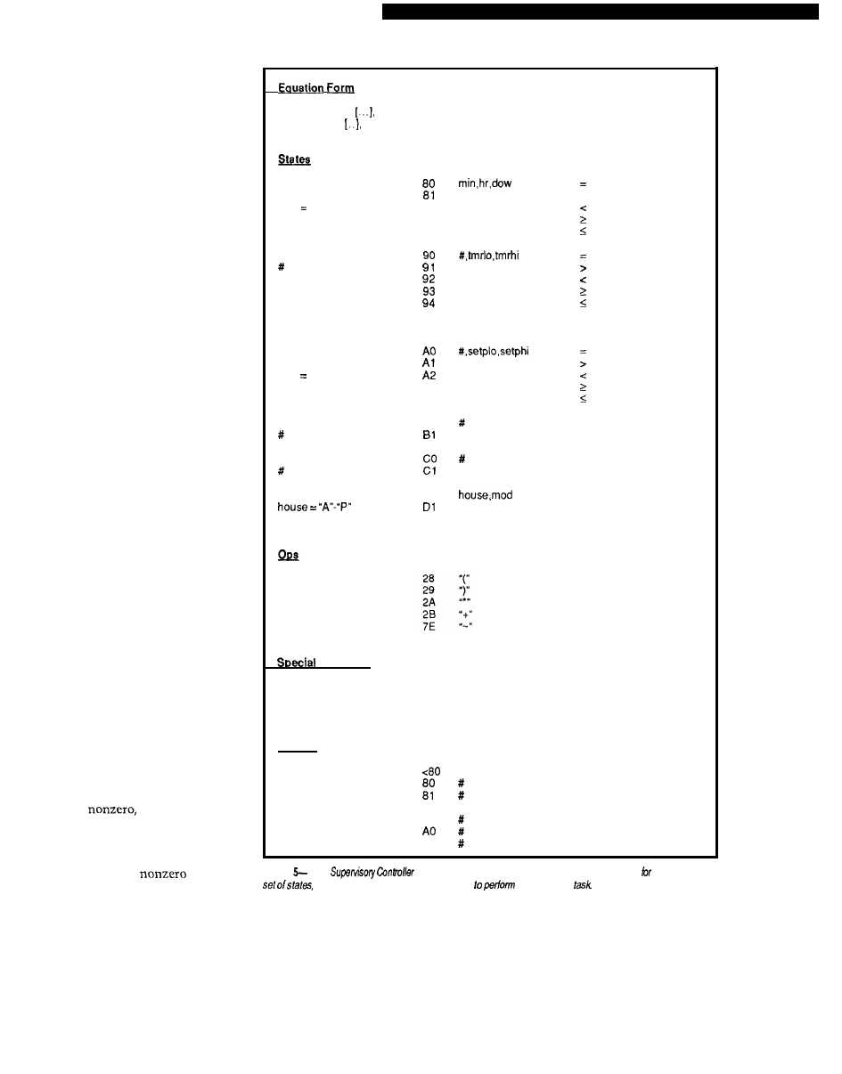
ming” scheme that made for very
simple, but very inflexible, operation.
When I set out to design something
new, I wanted a complete program-
ming language that could handle
complicated chores at my disposal.
I ended up basing the HCS II
language on what I call the “event
equation.” The entire control program
is made up of nothing more than a
series of event equations. The equation
consists of an “if” clause and a “then”
clause. Within the “if” clause, the
time of day, day of week, status of
inputs or outputs, status of timers,
state of variables, and so forth may be
tested, resulting in a true or false
answer. When the clause evaluates
true, the list of events defined in the
“then” clause is executed. If the “if”
clause evaluates false, the event list is
skipped and the next equation is
evaluated. Listing
1
contains a short
example of what a control program
looks like. Expressions in the “if”
clause of the equations may be nested
to any number of levels. Any number
of events may be defined within the
“then” clause.
Figure 5 gives the low-level details
about how the event equations are
stored in memory. The basic “if”
clause is made up of a pair of states
with an operator in the middle. Each
state may consist of a more compli-
cated expression within parentheses.
Multiple operators and states may
follow the initial pair. A “stop”
character indicates the end of the “if”
clause. The byte following the “stop”
is used to indicate whether or not the
expression has evaluated true on
previous passes through the equation
table. If the byte is zero, the expression
hasn’t been true before and if it’s true
now, the event list may be executed. If
the byte is
then this expres-
sion has already been evaluated true
and the event list has already been
executed. If the expression is true this
time, leave the byte
and skip
the events. If the expression is false,
set the byte to zero and, again, skip the
event list.
Following the flag byte is the
event list, terminated by a “last”
character. Figure 5 also shows the
allowable events.
state, op, state,
slop, 0
event, event, last
Time of Day
dow = 1-7
dow 0 for all
Timer
=o-15
tmr = O-65535
Analog Input
# = o-7
setp O-65535
Digital Input
= O-255
Boolean Variable
= O-15
X-10 Module
mod = 1-16
>
a2
a3
a4
98
#
on
99
Off
A3
A4
BO
on
Off
true
false
DO
on
Off
and
or
not
Delimiters
7F
stop
2F
last
00
end of table
Actions
90 #
91
Al
X-10 command
start timer
stop timer
output on
output off
variable true
variable false
Figure
The
has a complete
“home control machine language” defined if. This simple
operators, and actions can be combined
just about any
By now, the amount the SC must
keep track of should be apparent. It
must continually run through the list
of event equations, keep track of the
time of day, update internal timers,
watch inputs, send status information
to the host port, watch for user input
on the host port, and keep track of
network activity, all of which must be
done asynchronously and independent
52
Issue X25 February/March, 1992
The Computer Applications Journal

Listing 2-The EVAL routine is he core
the SC, and is
for evaluating tie
Evaluate the event expression pointed to by IX. This and
'evarg' are recursive routines that call each other while
evaluating an expression.
eval:
push
push
call
nextop:
inc
call
andop:
and
orop
evdone
or
ret
bc
de
evarg
Evaluate first argument
Save it
ix
stop
cparen
evarg
andf
orf
evdone
Get next operation
Done?
No,
save op
Evaluate next argument
Perform operation
Error in operator
C
nextop
C
nextop
bc
Listing
by EVAL evaluate individual arguments. EVARG
recursively
when the
passed
an
Evaluate the argument pointed to by IX
called by 'eval'.
evarg:
push bc
push de
push hl
NOT off
inc
ix
notf
NOT?
Recursively calls and
COMPUTER ANIMATION
FOR PROFESSIONALS
Animate static graphic images from your
favorite graphics program, user written
program, or post processor in real time!
Superior Tool For:
l
Scientific Visualization
Structural Dynamics
F r a c t a l s
Instructional Aid
high resolution, full color EGA
or VGA frames per second (typical)
routines for user written
programs in ‘C’, FORTRAN, Pascal,
and
Combine SLIDES and ANIMATIONS for
s e m i n a r s , c o n f e r e n c e s , a n d c l a s s r o o m s .
ONLY $199
PRINT SCREEN UTILITY
F A S T , c o m p a c t
6
1 4 v i d e o g r a p h i c
Complete 4 and
d
o
t
-
m
a
t
r
i
x
,
ECLECTIC
1106 St. David Ct. * Springfield, VA22153
(703)
FAX (703) 455-8965
For IBM-compatible computers
The Computer
Issue
February/March, 1992
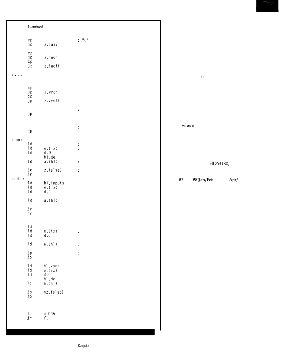
Listing
eval:
oparen
inpon
inpoff
other argument types including time of day.
X-10 module state, etc. are here
vartru
varfls
xor
a
Illegal arg. so eval false
argdone
lazy:
call
eval
Let EVAL do the work
argdone
add
or
add
or
vron:
add
or
vroff:
add
or
hl.inputs
Point to input storage
Offset to input in question
Get state
a
Off
if zero
true1
hl.de
a
nz.falsel
true1
hl.vars
hl,de
a
z.falsel
true1
true1
: Off if zero
: Point to variable storage
Offset to variable in question
Get state
False if zero
ialsel:
truel:
[continued)
of anything else on the system. Such a
setup screams for assembly language
and multitasking, and is just what I
used.
Figure 6 contains a somewhat
oversimplified block diagram showing
how the tasks are broken up. For all
intents and purposes, you can view the
system as if all the tasks arc running
simultaneously. Most communication
between the tasks accomplished
through the
USC
of shared memory. A
cardinal rule in any multitasking
system is no more than one task is
allowed to write to a memory location
at any given time. In most cases, you’ll
see in the block diagram no more than
one arrow going into a memory area,
though multiple out arrows are kosher.
In cases
there is more than one
in arrow, the arrows either go to
different regions within the area or
special safeguards are installed in the
tasks to make them cooperate with
one another.
For a good introduction to
multitasking with the
I
refer you to Jack Ganssle’s “Writing a
Real-Time Operating System” in
issues and
‘89 and
May ‘89) of
Circuit Cellar INK.
EVALUATE THE SITUATION
While multitasking and network
management are fine, the heart of the
system is a little (relatively speaking]
piece of code that evaluates the
equations. Evaluating an expression
that may contain any number of levels
of parentheses can be a nightmare if
straight-line code is used. Imagine
having to keep track of what level
you’re on in addition to all the inter-
mediate results. The microprocessor
has a device built into it that makes
such management almost trivial: the
stack.
Listing 2 contains EVA L, which
evaluates two or more arguments
separated by operators. The first
argument
is
evaluated and the result is
saved. The second argument is
evaluated, and the operator is applied
to the pair. If more operators and
arguments are present, they are
evaluated in sequence. The final
result is simply returned in the A
register.
54
Issue X25
February/March,
1992
The
Applications
Journal
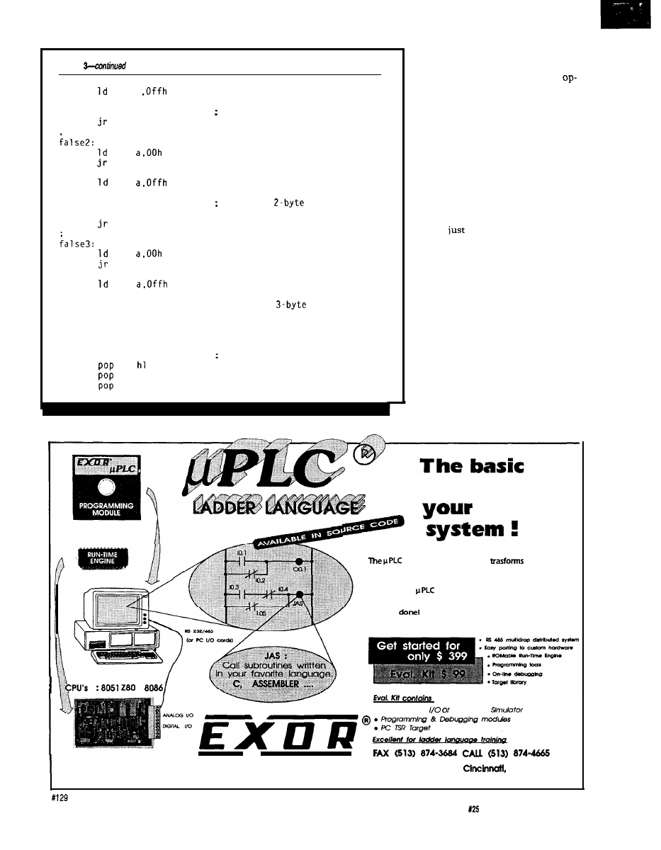
Listing
f l :
i nc
true2:
f2:
inc
inc
true3:
f3:
inc
inc
inc
argdone:
xor
ret
a
ix
argdone
Skip over l-byte argument
f2
ix
ix
argdone
Skip over
argument
f3
ix
ix
ix
: Skip over
argument
b
de
bc
Flip result if NOT flag set
Most of the work is obviously
done in
EVARG,
shown in Listing 3.
Upon entry, it checks for a NOT
erator and, if present, sets the flag that
flips the final state before returning.
Next, it checks for an open parenthe-
sis. If it finds one, then it knows the
argument contains a subexpression
that must be evaluated.
EVA L
is per-
fectly suited to the task, so is called to
evaluate the subexpression. But didn’t
EVAL
just call
EVARG?
And won’t
EVAL
simply turn around and call
EVARG
again to help evaluate the expression
EVARG
asked it to evaluate?
The trick is in the stacking. As
long as all the registers used by
EVAL
and
EVARG
are pushed on the stack
upon entry and restored upon exit, the
routines may recursively call each
other to get the job done. Intermediate
results are automatically stored. Most
computer science students see this
technique in the ever popular sorting
and factorial exercises. I’m happy to
say recursion has its uses in everyday
situations as well.
Now if both routines simply
continue to call each other, how is any
building block
for
control
LADDER LOGIC
YOUR EMBEDDED CONTROL SYSTEM
operating system kernel
your basic
microprocessor into a high- performance Programmable
Logic Control.
Just plug the
ROM into your favorite microprocessor
card, load the integrated programmer/debugger onto your
PC, connect a serial cable and begin taking the credit for a
job well
:
l
Parallel Port
On Screen
E L E C T R O N I C R & D
4850
interstate
Dr.
OH
45246
The Computer Applications Journal
Issue
February/March, 1992
55
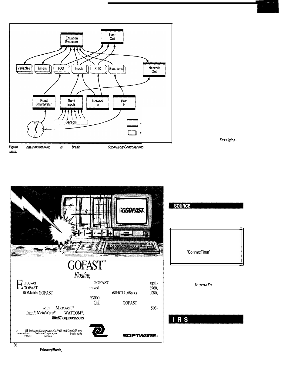
Task
MemoryBlock
6 - A
kernel used to
the operation of the
several independent
useful work going to get done? Notice
evaluate the argument for true or false
I said above that
EVA L
is called only if
and
EVA L
will finally have a real
EVARG
encounters an open parenthesis.
answer. The majority of code in
EVARG
If it doesn’t encounter one, then it can
simply checks to see what state is
Lightning-Fmt
Point Accelerators
your 80x86 applications with
IEEE accelerators are
accelerators. Fast, reentrant,
for 8051, 8096, 8086, 80386,
and
accelerators boost
6801, 6809,
8085,
Performance and make sure you can em-
and more.
bed your application.
for your free
information
Link and go
C:
Bor-
diskette today: 503-641-8446; FAX
land4
and
644-2413; 800-356-7097.
Dynamically replace
during
execution.
14215 NW Science Park Drive
1991
Portland, OR 97229
us
All other
belong
respective
U S
being tested, does the test, and
returns the result. I abbreviated
the code a bit in Listing 3 because
much of it is redundant.
EXPANDING YOUR
HORIZONS
So
what’s next? As I already
mentioned, Ed is presenting the
software for a series of network
modules that fill out the system.
Small installations would work
quite well with just the SC
presented here and the PL-Link
presented elsewhere in this issue.
Additional modules can be added
as the need arises. With the
internal SC code broken into
logical, independent sections, I
can easily add support for new
devices by adding a new task to
deal with that device.
line code would quickly become
spaghetti code if I tried to expand
it beyond the initial design
specification.
In the next issue of
Circuit Cellar
INK,
I’ll describe a compiler that takes
the control program you write with a
word processor and converts it to my
“HCS machine language” to be sent to
the HCS by the host software.
q
See
page
44
for information regarding
the availability of HCS II components.
Software for this article isavailable from
the Circuit Cellar BBS and on Software
On Disk for this issue. Please see the
end of
in this issue for
downloading and ordering information.
Ken Davidson is the managing editor
and a member
of
the Computer
Applications
engineering
staff.
He holds a B.S. in computer
engineering
and an
M.S. in
computer
science from
Rensselaer
Polytechnic
Institute.
407 Very Useful
408 Moderately Useful
409 Not Useful
56
Issue X25
1992
The Computer Applications Journal

:
Designing with the LM335 Temperature Sensor
by Mark E. Nurczyk, P.E.
Isolation Amplifier Design Using the IL300 Linear Optocoupler
by Bob Krause
The Computer Applications Journal
Issue
February/March, 1992
5 7
Designing
with the
LM335
Temperature
Sensor
Mark E. Nurczyk, P.E.
n a past “Firm-
ware Furnace”
column, Ed Nisley
used an LM335 to
measure the temperature of a water
pipe
(Circuit Cellar INK
October/
November 1990). As part of his article,
Ed specified the resolution available
from an unamplified LM335 as being
using an
analog-to-digital
converter, or
converter. His column started me
thinking, and this article is the result.
The LM335 has an output change
of
for every kelvin step. Zero
volts is at 0 K (1 kelvin degree = 1
Centigrade degree, 0°C = 273.15 K).
The transfer function of the LM335 is
Vout =
x temp. in
+ 2.73 15
The outputs of the LM335 at the
end points of its operational range are
a span of 1.4 volts. The
to-digital converter operates over the
input range of zero to five volts. As a
result, the
output only uses
28 %
of the A/D converter’s
input voltage range.
I wondered how much resolution
could be made available if a suitable
signal conditioning circuit translated
the LM335 output voltage to the input
range of the A/D converter. If the
output of the LM335 can be translated
to the 0-5-volt input range of the ADC,
the resolution can be increased to
for the
converter, and
for the lo-bit.
In this exercise we will be per-
forming a feasibility study. Such a
study can be very perplexing; you will
not know where you are going until
you have completed your journey. I
will not begin with a specification,
because the circuit cannot be specified
until we are finished and know what is
possible.
THE BASICS
A signal conditioning circuit that
subtracts 2.33 15 volts DC from the
output will translate the
output to 0 volts DC. The
output of the signal conditioner will
then be 0 to 1.4 volts. If the condition-
ing circuit also multiplies the
output voltage by 3.57
then the
translated output at 100°C will be 5
volts. An op-amp configured as a
differential amplifier is well-suited to
the task.
Figure shows the topology of a
differential amplifier. Many texts, such
as Walter Jung’s
Op-Amp Cook-
book,
derive the following transfer
function for the differential amplifier:
when
= R3
and R2 = R4.
Circuit design seems to be so
simple at times. Presumably, all that is
needed is to connect a voltage source
of 2.33 15 volts (the offset voltage) to
VA, connect the
output to
VB, and pick resistor values for a gain
of 3.57. When the
output
changes from 2.33 15 to 3.73 15 volts,
you would expect the op-amp’s output
to change from 0 to 5 volts, correct?
Well, yes and no. It depends
mostly on the type of op-amp used. For
example, an LMC660 is a true CMOS
op-amp. If the load has a high imped-
ance, its outputs will saturate to
within a few millivolts of its supply
voltage. If an LMC660 is used as the
amplifier, the output will span 0 to 5
volts to within less than one ADC bit.
On the other hand, an LM324 is a
bipolar op-amp. The limits of its
output are offset from its power supply
pins by the junction voltages of bipolar
transistors (typically around 0.6 V). If
an LM324 is used as the amplifier, its
output won’t be able reach the desired
limits of 0 and 5 volts (assuming a
single-ended 5-V power supply). Also,
for proper linear operation, biasing of
the input differential amplifier limits
X25 February/March, 1992
The Computer Applications Journal
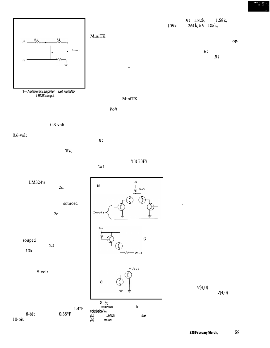
R 3
R4
Figure
is
conditioning the
the input voltages of both op-amp
types.
The input amplifier section of an
LM324 is shown in Figure 2a. The
current source has a
drop
across it, while each transistor has a
drop from its base to its
emitter. Therefore, the amplifier will
saturate whenever either input is
greater than 1.5 volts below
The
LMC660 has similar input structures
in CMOS. If the signal voltage needed
exceeds (V+)-1.5, there is no choice but
to provide a greater supply voltage to
power the op-amps.
The
output structure is
shown in Figures 2b and
When
sourcing current, the structure of
Figure 2b is used. As above, the
highest voltage that can be
is
1.5 volts below V+. Current sinking is
determined by Figure
The output
voltage is the sum of the NPN satura-
tion voltage and the base-emitter drop
of the PNP, or about 0.8 volts. The
various manufactures of the LM324
have
up the PNP so the output
voltage is less than millivolts if the
load is
or greater at 5 volts.
I’ll use the LM324 for this feasibil-
ity study. It is one of the most popular
bipolar op-amps currently in produc-
tion. Using a
power supply, the
voltage presented to the A/D converter
by an LM324 will vary from 0.02 volts
to 3.5 volts. This voltage span will
utilize 70% of the A/D converter’s
resolution, a little over double what
we started with, and will provide us
with a temperature resolution of
for the
converter or
for the
converter.
OFFSET AND GAIN
The first step is to determine the
amplifier’s offset and gain voltages.
an equation solving program
from Universal Technical Systems
Inc., is useful for solving the equations
involved. The basic equations to solve
for offset and gain are
Voutlo = (Vinlo Voff) x Gain
Vouthi = (Vinhi Voff) x Gain
To fit our system the following
constants are used: Voutlo = 0.02,
Vinlo = 2.3315, Vouthi = 3.5, and Vinhi
= 3.7315. To give
a starting
point, you have to enter estimated
values for
and Gain. Solving the
equations results in an offset voltage of
2.323 volts and a gain of 2.486.
The circuit we will use is shown
in Figure 3. The offset voltage is set by
the voltage divider made up of resis-
tors and R2. The gain is set by
selecting the proper values for R3, R4,
R5, and R6. Again using the computer
as a design tool, I used a pair of
programs I wrote called
. BAS
and
NRAT. BAS to determine the
proper resistor values, which turned
Figure
The input section of the ever-popular
LA4324
when either input greater than 1.5
The output sections are modeled as in
when he
is sourcing current; structure in
is used
sinking current
out to be =
R2 =
R3 =
R4 =
=
and R6 =
261 k, which are actually scaled from
what the programs predicted. You
don’t want the gain network of the
amp (R3 and R4) to load the voltage
divider made up of and R2. If R3
and R4 significantly load and R2,
the gain ratio will change as the
output voltage changes. I picked the
op-amp feedback network to be two
orders of magnitude greater in imped-
ance than the voltage divider network.
Usually one order of magnitude will
do.
MODELING THE SYSTEM
The student version of PSpice has
had some major functions added since
its last release. Some of the new
functions are shown in Listing 1, a
PSpice input file based on Figure 3.
E335, a voltage-controlled voltage
source, models the LM335 tempera-
ture sensor. The line that defines E33 5
contains a transfer function. VTEMP is
the controlling voltage source, its
output, in volts DC, corresponds to
temperature in degrees Fahrenheit.
E 3 3 5’s transfer function converts the
temperature from Fahrenheit to
Centigrade and multiplies by the
voltage change per degree. Finally it
adds an offset to bring the output
voltage to the correct value.
The WCAS E line performs a
worst-case analysis, which determines
circuit parameter values which will
cause the poorest circuit performance
based on defined component toler-
ances. First, the worst-case analysis
determines the sensitivity of the
defined circuit node waveform to each
device that has a specified tolerance.
At the end of the analysis, each device
is set either high or low to give the
worst-case waveform. The PSpice
output file will contain the nominal as
well as the worst-case value.
EOUT, another voltage-controlled
voltage source, is defined as a table
function. When
is zero, the
output is 0.02 volts. When
is
3.5, the output is 3.5 volts. The output
is the linear interpolation of 0.02 to 3.5
when the input is between 0 and 3.5.
Also, the output is limited and will
never go above 3.5 or below 0.02.
The Computer Applications Journal
Issue
1992
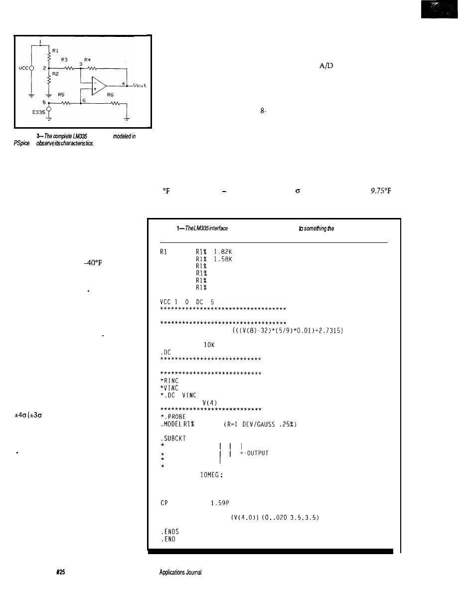
VTEMP was set to the three
temperatures shown at the top of
each column. The temperatures
in the last four rows are derived
using the following procedure:
The voltage values in the nominal
voltage row are turned into bit
values with fractional parts by
dividing them by 0.0195 (for an
bit converter). A linear regression
Figure
interlace is
is next performed on the nominal
to
bit values and temperatures to
find the best-fitting straight-line
equation of the form y=mx+b.
Listing 1 shows the worst-case
The temperature equation turns out to
section commented out. The circuit is
be
run to check the input and output
waveforms, with Figure 4 showing the
results. Node voltage
V(5)
shows the
LM335 output voltage. I used the
PSpice cursor to show the value of
V(5)
at 40°F and 212°F. The modeling of the
LM335 produces the proper voltages at
each temperature. V(4) shows the
amplifier is working as desired, with
an output of 0.02 V at
and 3.5 V
at 212°F.
Now run the worst-case analysis
by commenting out the DC line in the
temperature sweep section and
removing the leading asterisks from
the worst-case section. The device
values used will be determined from
the tolerance specified in the MODE L
statement. The Gaussian distribution
(a bell-shaped curve) most closely
approximates the tolerance distribu-
tion of electronic parts. The tolerance
value you use should be one fourth of
the part tolerance for Gaussian
distribution. The end points of a
Gaussian distribution in PSpice are at
contains 99.73% of the
population).
Run the worst-case analysis twice,
first with the MAX keyword in the
WCASE statement and second with
the MI N keyword. MAX finds the
maximum value of the specified node
voltage or component current; MI N
finds the corresponding minimum
value. By including two complete
circuit descriptions in one PSpice
input file, both sets of results can be
sent to a single output file from a
single PSpice run. The worst-case
results for our circuit are shown in
Table 1.
Next, the bit values at the maxi-
mum and minimum limits are
determined and truncated to whole
numbers. An
converter knows
nothing about fractional bits-it
doesn’t round, but truncates. The
truncated bit values are changed into
temperatures using the temperature
equation derived above. This equation
can be used by a microcomputer to
transform the raw A/D bit values into
scaled engineering units.
During a large production run,
using 1% tolerance resistors, the
temperature error due to the amplifier
circuit can approach almost 13°F.
= (1.4288 x bits) 42.6297
Luckily, 99.73% of the amplifiers (the
three points) will be within
(0.75 x 13). Using 0.1% resistors-the
Listing
shown in figure 3 is translated
computer can
understand.
1
2
R2
2
0
R3
2
3
105K
R4
3
4
261K
R5
5
6
105K
R6
6
0
261K
Xl
6
3
4
LM324
*** Temperature Sweep Section ***
E335
5 0
VALUE =
VTEMP 8 0
DC -35
RTEMP 8 0
VTEMP
-45 220 1
*** Worst Case Section ***
100
0 1
100
0 DC 1
0 1 1
*.WCASE DC
MAX
R E S
* OPAMP MACROMODEL SUBCIRCUIT
LM324
1 2 3
+----INVERTING INPUT
+-------NON INVERTING INPUT
RIN
1
2
INPUT IMPEDANCE
* GAIN AND PHASE CONTROL
GM
0
4
12 1
RG
4
0 100000
4
0
*
OUTPUT SECTION
EOUT
5
0
TABLE
ROUT
5
3
25
60
Issue
February/March, 1992
The Computer
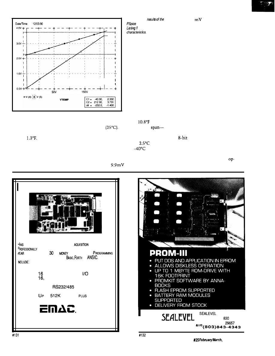
run
14 29 36
Temperature 27 0
-50v
o v
1 oov
2oov
250V
most commonly available commercial
parts with the tightest tolerance-will
reduce the error by an order of magni-
tude to
Close matching of the
resistor values over the temperature
range is essential for proper circuit
operation.
The amplifier error must be added
to the error of the LM335. The LM335
Figure 4-The
grade to 10.1
per degree Centi-
simulation defined in
show the circuit’s
grade.
The calibration error of the LM335
is an offset error. If the calibration
error of the individual LM335 is
known, the offset, when appropriately
scaled, can be added to the bit value in
the temperature equation. The
amplifier error may be a combination
of offset error and slope error. Applying
two precise ambient temperatures to
the LM335 allows the microcomputer
to determine a slope and offset
correction for the amplifier and LM335
sensor combination. Of course, some
sort of nonvolatile memory is required
to store the calibration data.
PUSHING THE DESIGN
has a calibration error of
(6°C)
at 77°F
The variation in
the algebraic difference between
maximum and minimum tempera-
tures-can be as much as
over
the operating range of
to 100°C.
Consequently, the slope of the tem-
perature equation of the LM335 may
vary from
per degree Centi-
Now that we know how to design
a differential amplifier with arbitrary
offset and gain, let’s “push it” a little.
The
A/D converter that Ed used
in his article has eight inputs. If the
application permits, all eight inputs
can be used for one measurement.
Eight amplifiers, using LM324
amps, are theoretically equivalent to
INDUSTRIAL STRENGTH
SINGLE BOARD COMPUTER
OPTIMUM FEATURES FOR DATA
AND CONTROL.
DESIGNED AND BUILT FOR TOUGH APPLICATIONS WITH A
2
WAR
R
A N
T
EE AND A
DAY
SACK GUARAN
T
E E
.
S A SNAP IN EITHER MULTI-TASKING
OR
FEATURES
*
80PTICALLY COUPLED DIGITAL INPUTS
*
8 HIGH DRIVE BUFFERED DIGITAL OUPUTS
*
PROGRAMMABLE DIGITAL
LINES
*
THIRTEEN
BIT
ANALOG
INPUTS
*
2
OPTIONAL
TWELVE BIT ANALOG
OUTPUTS
*
4 SERIAL
SERIAL PORTS
* 6 TIMER/COUNTERS
*
TO
MEMORY
EEPROM
*
E-PAC 3000 G2 COST $389.00
Q T Y
. 1
inc.
618-529-4525
Fax 618-457-0110
P.O. BOX
2042,
CARBONDALE, IL 62902
SYSTEMS INC.
PO BOX
LIBERTY, SC
COMMUNICATIONS
I
The Computer Applications Journal
Issue
1992
61
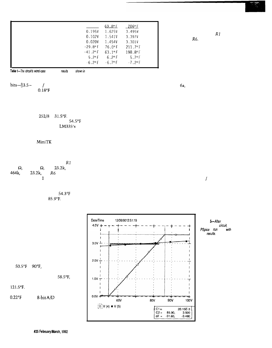
Maximum voltage
Nominal voltage
Minimum voltage
Maximum temperature
Minimum temperature
Tolerance error at Max
Tolerance error at Min
- 3 5 ° F
analysis
are
tabular form
an A/D converter that spans 1,427
0.20) 0.01951 x 8-giving
a resolution of
over the -40°F to
212°F operating range of the LM335.
I’ll detail the design of one
amplifier in about the middle of the
temperature range. Each amplifier wi!l
span a range of
or
We
will concentrate on the range of
to 86°F. For this range, the
end points are 2.8565 volts and 3.0315
volts, respectively.
Using the
equations
described above, we find the gain has
to be 19.89 and the offset 2.855 volts.
My two custom programs indicate the
resistors in Figure 3 should be =
187 R2 = 249 R3 =
R4 =
R5 =
and
= 464k. I
modified Listing to reflect the above
values and obtained the results shown
in Figure 5. The results are pretty
close; minimum output at
and
maximum output at
Now all
we have to do is repeat this design
exercise seven more times and we are
done. Perhaps, but first check the
worst case.
The worst-case results for our
enhanced circuit are shown in Table 2.
They show that the end points of
adjacent temperature ranges don’t
necessarily meet. To get a continuous
function, the end points of each range
have to overlap by almost 8°F. The
range we looked at above should really
be
to
with the consequent
gain of 15.86 and offset of 2.833. The
preceding range is 15°F to
while the next range is 82°F to
Taking the overlap into
account, we can expect a resolution of
with an
converter.
THE CALIBRATION PROBLEM
Now there is a large problem.
Each of the eight ranges has to be
separately calibrated, at two points
each, for gain and offset errors. To
calibrate the amplifiers, precision fixed
resistors can be used to simulate the
LM335. Complicated software has to
be written which knows when the
calibration is being performed and
what range is being calibrated. Perhaps
the best way to proceed is to have the
embedded controller to which the
signal conditioning is attached
communicate with a PC during
calibration. The PC can worry about
applying the proper resistors at the
correct time, performing all the
mathematical gymnastics on the
conversion results, and determining
the calibrated slopes, offsets and
endpoints for each range. A single- or
dual-point calibration of the LM335
can be performed concurrently. The
PC can calibrate many, many assem-
blies quickly.
Calibrating many amplifiers is
costly and time consuming. Producing
large numbers of assemblies may not
be cost effective. Most of the error is
due to mismatches between and
R3, and R4 and
The first circuit most engineers
would pick for this job is a differential
amplifier, which is why I have shown
circuits based on such a configuration.
However, simpler inverting or
noninverting amplifiers can perform
the same function.
A noninverting amplifier, shown
in Figure produces an output
voltage slope with the same sign as
that of the input voltage slope. The
input voltage is connected to the
noninverting input of the op-amp
while the offset voltage is connected to
the resistor feedback network. To
determine the amplifier’s output
voltage, look at the contribution of
each voltage source on the output and
add them together.
From the viewpoint of the offset
voltage source, the noninverting
amplifier actually looks like an
inverting amplifier. The output voltage
due to the offset voltage contribution
is
Voffset x (-Rf Rin)
To the input voltage source, the
noninverting amplifier truly looks like
a noninverting amplifier. The output
voltage due to the input voltage
run:
Temperature: 27.0
5ov
7ov
VTEMP
54.30,
Figure
enhancing he
is
again
flew
62
Issue
The Computer Applications Journal
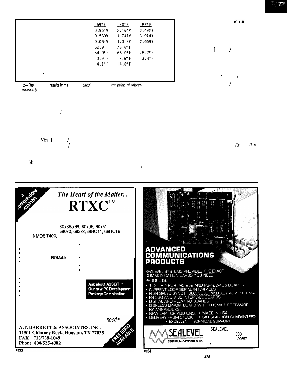
M a x i m u m v o l t a g e
Nominal vol tage
M i n i m u m v o l t a g e
M a x i m u m t e m p e r a t u r e
M i n i m u m t e m p e r a t u r e
T o l e r a n c e e r r o r a t M a x
T o l e r a n c e e r r o r a t M i n
N o t e :
= ( 0 . 1 7 7 x b i t s ) + 5 4 . 2 0 8
85.8” F
-3.8” F
Table
worst-case
enhanced
show that the
temperature ranges
don’t
meet.
contribution is
Vin x 1 + (Rf Rin)]
When added together, the output
voltage is
Vout =
x 1 + (Rf Rin)]}
[Voffset x (Rf Rin)]
An inverting amplifier, shown in
Figure
generates an output voltage
slope with a polarity opposite that of
the input voltage’s. The offset voltage
is connected to the noninverting input
of the op-amp while the input voltage
is connected to the resistor feedback
network. The contributions of each
voltage source at the output are added
together to come up with the amplifier
output voltage.
The amplifier looks like an
inverting amplifier to the input voltage
source. The output voltage due to the
input voltage contribution is
Vin x (-Rf Rin)
The amplifier looks like a
verting amplifier to the offset voltage
source. The output voltage due to the
offset voltage contribution is
Voffset x 1 + (Rf Rin)]
When added together the output
voltage is
Vout = {Voffset x 1 + (Rf Rin)]}
[Vin x (Rf Rin)]
Gain and offset voltages for both
inverting and noninverting amplifiers
can be found using the same technique
described above.
The gain in these two amplifiers is
only dependent on the ratio of two
resistors and not their absolute values,
so is an ideal application of a potenti-
ometer. Substituting a potentiometer
for the network made up of and
allows a smooth progressive change in
amplifier gain. One end of the pot is
connected to the voltage source and
the other end pot is connected to the
amplifier output. The pot wiper is tied
Real-Time Multitasking Executive
l
INTEL
l
MOTOROLA
l
T800
l
ANALOG DEVICES 2100
l
Preemtive Scheduling
Fixed or Dynamic Priorities
Timeout on some services
Configurable and
Intertask Communications
-Messages
-Queues
-Semaphores
Memory Management
Resource Manager
Written in C
l
Source Code Included
l
No Royalties
Technical Support
l
Broad C Compiler Support
Sensible License Agreement
Most Popular C Compilers
supported
Over 50 Executive Services Available
System Level Debugging Utility
System Generation Utility
One Time License Fee From $995
Discounts for Multiple Licenses/Ports
The only real-time kernel you’ll ever
SYSTEMS INC.
PO BOX
LIBERTY, SC
( 8 0 3 ) 8 4 3 - 4 3 4 3
The Computer Applications Journal
Issue
February/March, 1992
6 3
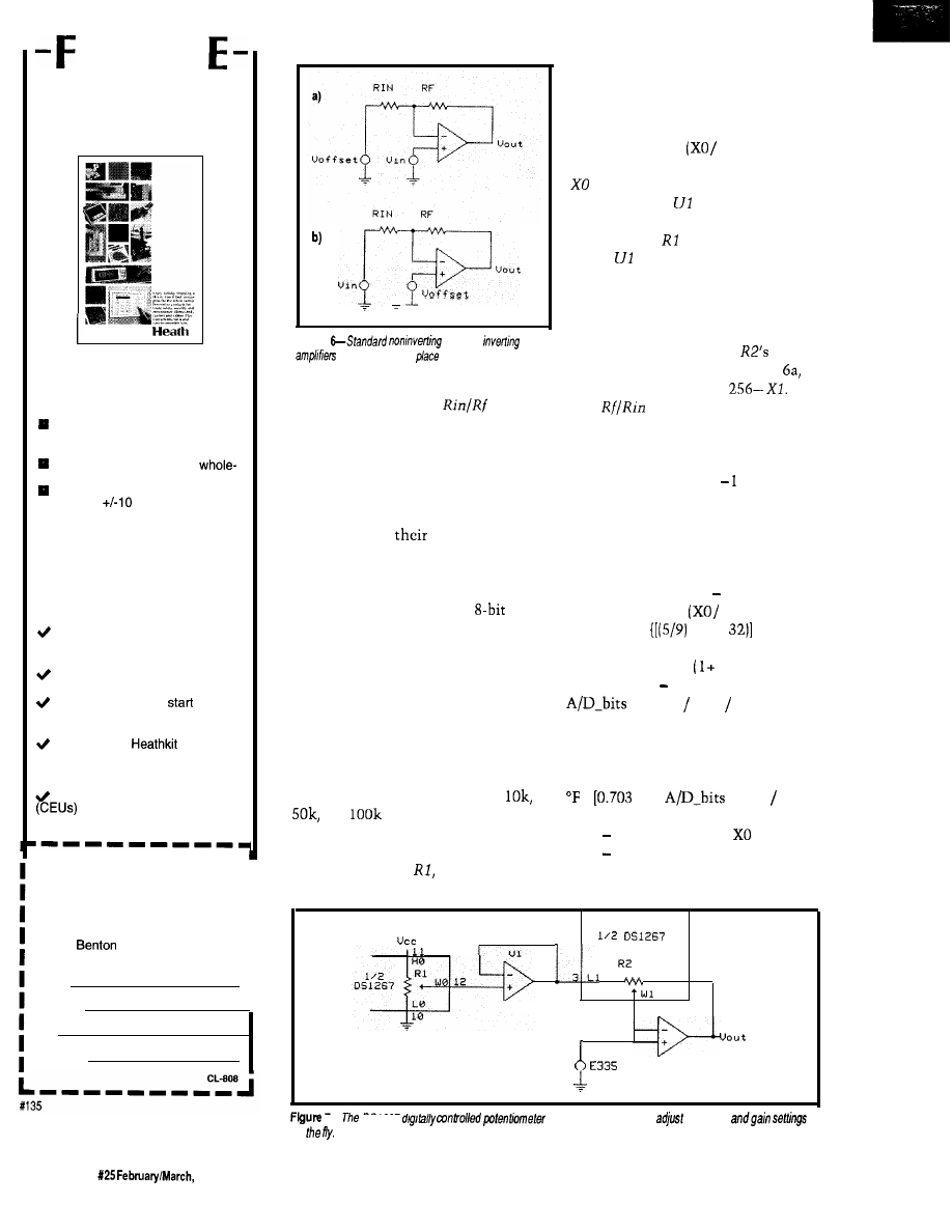
R
E
HEATH
CATALOG
New and innovative
electronics that make your
life easier, safer and more
secure, including:
The world’s largest and most
varied selection of home lighting
controls.
Home security, safety and
house automation systems.
The Heath Most Accurate Clock,
accurate to
milliseconds.
q
Heath’s own Advanced Weather
Computer for precision weather
display and analysis.
And, the best electronics
home study programs you’ll
find anywhere (the best
value, too) including:
New Computer-Aided Instruction
(CAI) courses in basic electronics
for accelerated, interactive learning.
Video courses you can watch
from the comfort of your easy chair.
Courses that let you
at the
level that’s right for you and continue
at your own pace.
Courses from
Educational Systems, accredited
and licensed as a premier electron-
ics educator.
Continuing Education Units
awarded on successful
completion of most Heath courses.
To receive your FREE Heath
Catalog, fill in your name and
I
address below and mail TODAY!
I
To:
Heath Company
I
Dept. 026-140
Harbor, Ml 49022
I
I
Name
I
Address
I
City
State/Zip
Figure
(a) and
(b)
may be
used in
of he
differential
amplifier.
to
the point where the
junction
is normally connected. Taking it one
step further, controlling the potenti-
ometer by the microcomputer would
allow virtually any resolution of the
input voltage to be synthesized.
pots are connected to pins on the chip,
and both potentiometers have the
Dallas Semiconductor comes to
the rescue with
DS1267, a dual
digitally controlled potentiometer
chip. Each potentiometer is composed
of 256 resistive sections. The pot wiper
position is controlled by an
number sent over a d-wire serial port.
Any value between 0 and 256 can be
sent independently to each potentiom-
eter. The tap point of the wiper on the
resistor array is controlled by the value
sent to the serial port. Each end of the
resistor array and the wiper of both
generate an offset voltage. The voltage
developed by the potentiometer is
calculated using
Vcc x
256)
is the digital value used to set the
wiper position.
is a unity gain
buffer amplifier used to present a high
impedance to
and a low impedance
to R2.
keeps the gain ratio from
changing as the output voltage
changes.
The other pot, R2, is used to set
the amplifier gain. The digital value
used to set the position of
wiper,
Xl, corresponds to
Rin in Figure
while
Rf corresponds to
The
ratio
becomes
o r
(256 -Xl) /Xl
(256 /Xl)
The following system of equations
describes the operation of the circuit
shown in Figure 7:
G a i n
= (256 /Xl) 1
Voffset
= Vcc x
256)
Vin
=
x (“F-
+ 273.153
x 0.01
Vout
= [Vin x
Gain)]
(Voffset x Gain)
= Vout (Vcc 256)
to produce a single equation:
This system of equations can be solved
same resistance value. Values of
and
are available.
A noninverting amplifier circuit
using the digital pots is shown in
Figure 7. One pot,
is used to
=
13 x
x (Vcc 256)
x Xl] + (0.70313 x vcc xX0)
(0.002747 x Vcc x
x Xl)
459.67
HI 2
4
u 2
I -
on
US1267
allows the computer to
the offset
64
Issue
1992
The Computer Applications Journal
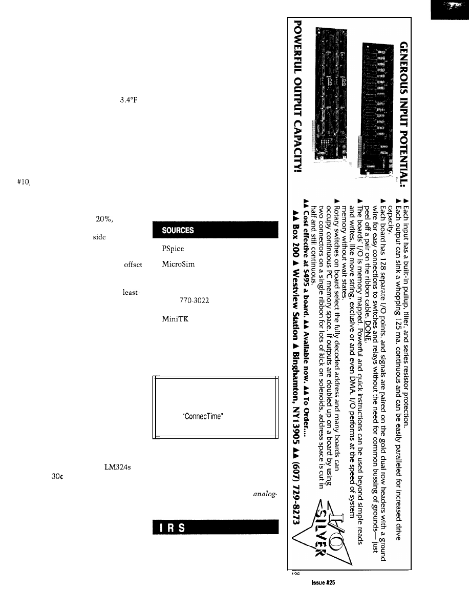
This final equation can be used by a
microcomputer to transform the raw
A/D bit values into scaled engineering
units.
Solving the equation at different
gains and temperatures shows the
resolution can be as great as 73 bits per
degree Fahrenheit and as low as
per bit. Be careful at higher gains.
Small amounts of noise present in any
electronic system may cause wild
fluctuations of the amplifier’s output.
Convolution techniques described in
Jack Ganssle’s article “Signal Smooth-
ing-Taking the Rough Edges off of
Real-World Data”
(Circuit Cellar INK
August/September 1989) may be
required to produce a stable tempera-
ture measurement.
Potentiometers typically have
end-to-end tolerances of
as does
the DS1267. Because it is the ratio of
the resistances on each
of the
wiper to one another that determines
offset and gain, the end-to-end toler-
ance is immaterial. The gain and
errors arc only determined by the
potentiometer’s linearity. The DS1267
has a specified linearity of half a
significant bit, or 0.2%.
When applying the circuit of
Figure 7, do not start the conversion at
high gains where it is easy to saturate
the amplifier. Vary the gain and offset
slowly; creep up on the values.
SUMMING IT UP
We have looked at three different
methods of interfacing an LM335 to an
analog-to-digital converter. Which is
the best method? All of them! You get
to pick the best one for your applica-
tion.
The digitally controlled potenti-
ometer amplifier is the most versatile.
Gain and offset can be changed at any
time to optimize performance. You
pay for versatility, though.
cost about
and the DS1267 costs
$2.50, both in OEM quantities.
The differential amplifier with
fixed resistors is fairly versatile, too. It
can be set to any offset and gain
desired, but cannot be changed once
built. I did not show them in a fixed
gain and offset configuration, but
inverting and noninverting amplifiers
can be used for this function as well.
The cost is very low-about a penny
each for the resistors in addition to the
op-amp.
Ed’s circuit is certainly the least
expensive: $0.
Now that you have a better idea of
what is possible, it is time to develop
the functional requirements for your
own temperature input circuit. The
cost and performance tradeoffs
required by your application define
which signal conditioning circuit to
use. Be sure to make your functional
requirements complete. For example,
there is the obvious requirement of
reading temperature to some arbitrary
resolution. Also, don’t forget resis-
tance to destructive transients or
misapplication. The list goes on..
q
Corp.
20 Fairbanks
Irvine, CA 92718
(800) 245-3022
(714)
Universal Technical Systems, Inc.
1220 Rock St.
Rockford, IL 61101
Software for this article isavailable from
the Circuit Cellar BBS and on Software
On Disk for this issue. Please see the
end of
in this issue for
downloading and ordering information.
Mark Nurczyk is a Registered Profes-
sional Engineer with nineteen years
experience in analog and digital
design. He works for a large OEM
designing microcomputer- and
based machine controls..
410 Very Useful
411 Moderately Useful
412 Not Useful
The Computer Applications Journal
February/March, 1992
6 5

Isolation
Amplifier
Design
Bob Krause
Using the
IL300
Linear
Optocoupler
isolation
is desirable and
often essential in
many measurement
systems. Applications such as indus-
trial sensors, medical transducers, and
switch mode power supplies require
isolation and insulation between the
mains primary and secondary. Opera-
tor safety and signal quality are also
ensured with isolated interconnec-
tions. These isolated interconnections
commonly use isolation amplifiers.
The IL300 linear optocoupler is a
new circuit element from Siemens
that enables designers to easily
develop high-quality isolation amplifi-
ers. The
common mode
rejection (CMR),
stability,
and
linearity provide a quality
link from the sensor to the controller
input. Its 7500-V withstand test
voltage (WTV) insulation, DC re-
sponse, and high CMR are features
which assure patient safety and
accuracy for the transducer signals.
The linear coupler’s
band-
width and gain stability make it an
excellent candidate for subscriber and
data phone interfaces. With switch
mode power supplies currently
approaching l-MHz switching frequen-
cies, they often need output monitor-
ing feedback networks with wide
bandwidth and flat phase response.
The IL300 satisfies these needs with
simple support circuits.
CHARACTERISTICS OF THE IL300
The IL300 consists of a
efficiency
IR LED emitter
optically coupled to two independent
PIN photodiodes. These three semi-
conductors are assembled in an 8-pin
DIP plastic package using a
voltage double-molded insulation
process, and satisfies UL and VDE
0884,
safety requirements.
Figure 1 shows the package
footprint and the
electrical
schematic. The servo photodiode
provides a feedback signal which is
used to control the LED’s
forward
current. The servo photodiode provides
a photocurrent, I,,, that is directly
proportional to its incident flux.
Operating the LED in an optical servo
loop linearizes the LED’s output flux
and eliminates the LED’s time and
temperature drift. The galvanic
isolation between the input and the
output is provided by a second PIN
photodiode
located on the output
side of the coupler. The output
photodiode current,
accurately
tracks the photocurrent generated by
the servo photodiode.
ISOLATION AMPLIFIER DESIGN
TECHNIQUES
The
photodiodes can be
operated as photovoltaic or photocon-
ductive current sources. The
(zero biased) mode offers the best
linearity, lowest noise, and best drift
performance. Isolation amplifiers using
this circuit configuration are suitable
for
A/D applications.
ductive (reverse biased] photodiode
operation provides the largest coupled
frequency bandwidth. The photocon-
ductive configuration has linearity and
drift characteristics comparable to an
or
A/D converter.
Either of the above photodiode
modes can be used to create isolation
l-The
uses a single LED and a pair of
detectors.
6 6
Issue X25
1992
The Computer Applications Journal
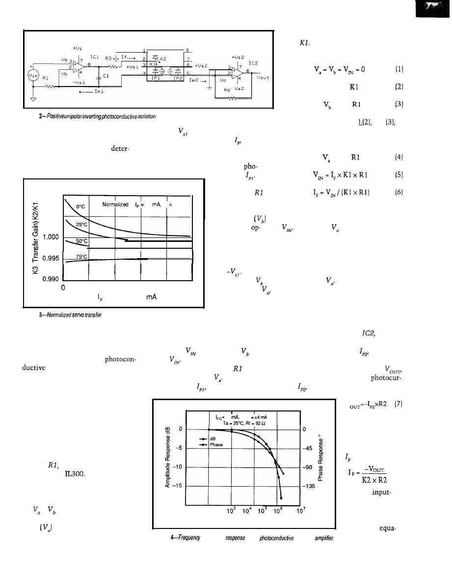
I L 3 0 0
1
amplifiers that will couple either
positive rail, and forward bias the
unipolar or bipolar input signals. The
LED. As the LED current, starts to
optimum circuit topology is
flow, an optical flux will be generated
mined by the input voltage range,
which will irradiate the servo photo-
transfer gain, bandwidth.
diode causing it to generate a
tocurrent, This
photocurrent will
1.010
flow through
to
10
Ta 25°C
and develop a
1.005
positive voltage at
the inverting
input of the
amp. The amplifier
output will start to
swing toward the
negative supply
rail,
When the
5
1 0
15
20
25
magnitude of is
(LED Current)
equal to that of
the LED drive
current will cease
Figure
amplifier.
Figure
gain.
to
increase. This
condition servos
PHOTOCONDUCTIVE ISOLATION
AMPLIFIER
the circuit into a stable closed-loop
condition.
The following analysis shows the
equations used to design a
inverting isolation amplifier
that will respond to a positive unipolar
signal. This amplifier topology is best
suited for communicating input
signals that have a positive offset
above virtual ground. The typical
operation of an IL300 isolation amp is
more easily understood by reviewing
the circuit shown in Figure 2.
When
is modulated, will
track
In order for this to happen,
the photocurrent through must also
track the change in Recall that the
photocurrent,
results from the
5
45
10
Mod
The input circuit consists of an
operational amplifier, ICI, a feedback
resistor,
and the servo photodiode
section of the
The servo
photodiode is a current source operat-
ing in the photoconductive, or reverse
biased, mode. The initial conditions
are
=
= 0
V. When a positive
voltage is applied to the noninverting
input
of the op-amp, the output of
the op-amp will swing toward the
The
-20
output gain of the
10’
-180
isolation amplifier
F (Frequency) Hz
is determined by
combining
Figure
and phase
of the
isolation
tions (6) and (9).
change in LED current times the servo
gain,
The following equations can
be written to describe this activity:
I,, = I, x
= I,, x
Combining equations (1
and
the relationship of LED drive to input
voltage is presented.
= I,, x
Equation 6 shows that the LED
current is related to the input voltage
A changing causes a modula-
tion in the LED flux which will change
to a level that generates the necessary
servo photocurrent to stabilize the
optical feedback loop. The LED flux
will be a linear representation of the
input voltage, The servo photo-
diode’s linearity controls the linearity
of the isolation amplifier.
The next step in the analysis is to
evaluate the output section of the
amplifier. This circuit consists of a
transresistance amplifier,
which
is connected to the output PIN photo-
diode. The photocurrent,
is derived
from the same LED that irradiates the
servo photodetector. The output,
is proportional to the output
rent,
times the transresistance, R2.
V
I,, = K2 x I,
(8)
Combining (7) and
(8) and solving for
is shown in (9).
( 9 )
The Computer Applications Journal
Issue X25 February/March, 1992
67
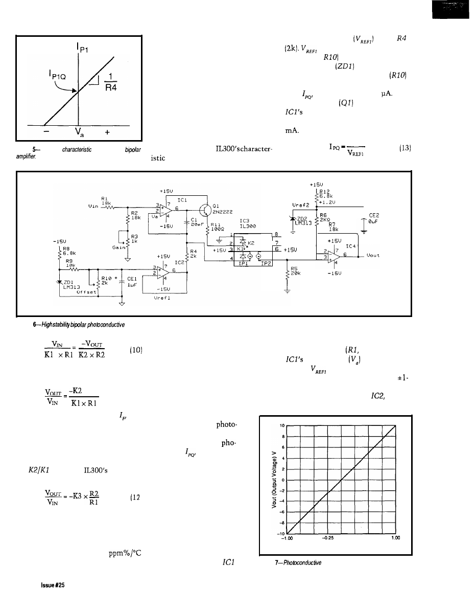
This analysis shows that isolation
amplifiers using the IL300 are not
plagued with the gain and temperature
drift problems associated with the
standard phototransistor optocoupler.
The preceding analysis showed how
the servo operation of the IL300
eliminates the influence of LED
characteristics on the isolation
amplifier transfer gain.
The photoconductive type of
amplifier design permits bandwidths
Figure
Transfer
of a prebiased
which approach the
frequency response in Figure 4.
the reference voltage
across
is derived from the voltage
divider (R9,
and the LM3 13
reference diode
as given in
equation (12). The offset control
is used to set the quiescent photocur-
rent,
to approximately 50
A
buffer transistor
is included at
output to allow it to easily
supply the typical LED current of 7
R4
+
5
Figure
isolation amplifier.
The solution for the input-output gain
is given in equation (11).
x R2
(11)
Note that the LED current, is
factored out of equation (11). This is
possible because the servo and output
photodiode currents are generated by
the same LED source. This equation
can be simplified further by replacing
the
ratio with
transfer
gain, K3.
Figure 3 shows the consistency of
the normalized K3 as a function of
LED current and ambient temperature.
The transfer gain drift as a function of
temperature is typically *SO
over a 0-75°C range.
BIPOLAR PHOTOCONDUCTIVE
The
input voltage range is set by
ISOLATION AMPLIFIER
the voltage divider
R2, R3) so
Telephone and audio applications
input voltage
does not
require the isolation amplifier to
exceed
(-0.1
V). These resistors
respond to bipolar signals. A prebiased
provide a 10: 1 divider permitting a
or offset isolation amplifier permits
V input range.
the servo amplifier to respond to
The output amplifier,
is an
bipolar signals. The prebias
forces the LED to produce a
current in the servo
diode with a zero voltage
input. This quiescent
tocurrent,
is then ampli-
tude modulated by the bipolar
input signal. The relationship
between the servo photocur-
rent and the input voltage is
shown in Figure 5.
The isolation amplifier,
shown in Figure 6, consists of
a noninverting servo input
amplifier and a noninverting
output voltage amplifier. A
prebias, I,,, is introduced at
the inverting input of
by
offset noninverting voltage amplifier.
- 0 7 5 -0.50
0.00
0.25
0.50
0.75
Vin (Input Voltage) V
Figure
amplifier transfer gain.
68
February/March, 1992
The Computer Applications Journal

Quality
cards and software for single user,
OEM, or embedded applications.
200
THROUGHPUT
S.E. analog inputs,
5
interface DMA transfer
*Trigger-in and trigger-out; pacer clock
4 Conversion modes channel scan
4 Independent timer/counters
16
digital
lines
*Assembler, BASIC, Pascal C source code
PRODUCTS
with
DM402
analog I/O board with
trigger, T/C, DMA I6 DIO lines $395
DM602
D/A; voltage range
select: current loop DIO control . . . . .
DM802
opto 22 compatible
PPI-based DIO interface
$149
POPULAR XT/AT PRODUCTS
AD1000 8
A/D inputs; 25
throughput; three
timer/counters; 24
PPI-based digital I/O lines.
$275
ADA1100
with 38
throughput,
2 D/A outputs, and configurable gain
$365
ADA2000 8
S.E. analog inputs;
bit 20 A/D; 12 or 8 A/D optional; two
bit D/A outputs: programmable gain; 3
DIO lines from
PPI
$489
ADA3100 8
analog inputs;
200
throughput: gain select; FIFO inter-
face DMA transfer; pacer clock; external
trigger; 4 conversion modes, multi-channel
scan channel burst;
DIO lines;
two fast-settling analog outputs
$659
AD510 8 S.E. inputs;
integrating A/D
with programmable gain $
2
5
9
4
inputs;
V/F type A/D;
variable resolution conversion
Hz;
D/A, T/C DIO lines
$410
Fast-settling
-channel
D/A; double buffered
Digital
lines;
based;
optional buffers line resistors
TC24
System Timing
Digital I/O control card
$218
MX32 External analog multiplexer $198
Menu-driven, real-time monitoring, control,
data acquisition and analysis turn-key soft-
ware packages
Call for your Free Catalog!
Real Time Devices, Inc.
State College,
PA USA
FAX:
F (Frequency) Hz
Figure
common mode
The
output offset,
is provided to
compensate for offset introduced in
the servo amplifier. The output
photocunent to voltage conversion is
provided by
The amplifier gain of
10 is set by the
network. The
voltage gain of this isolation amplifier
is given in equation 14).
The offset
is adjusted to
compensate for the output offset
The precise offset voltage is
predicted by equation (15).
V
x
R4
x
R 7
=
The output stage offset,
is
supplied by the LM3 13 1.2-V reference.
With a unity K3 the
is adjusted
to be -0.108 V.
This isolation amplifier has a
transfer gain of 10, given K3 = 1 .O and
the resistor values selected. The input/
output voltage characteristics of the
amplifier are shown in Figure 7.
NOISE REJECTION
One of the principal reasons to use
an isolation amplifier is to reject
electrical noise. The circuits presented
thus far are of a single-ended design.
The common mode rejection, CMR, of
these circuits is set by the CMR of the
coupler and the bandwidth of the
output amplifier. The typical common
mode rejection for the IL300 is shown
in Figure 8.
ISOLATION
AMPLIFIER
The
schematic of a typical
positive unipolar photovoltaic isola-
tion amplifier is shown in Figure 9.
The input stage consists of a servo
amplifier, ICI, which controls the LED
drive current. The servo photodiode is
operated with zero voltage bias which
is accomplished by connecting the
photodiodes anode and cathode
directly to
inverting and
noninverting inputs. The servo
photocurrent is linearly proportional
to the input voltage, =
The
servo photocurrent resulting from the
LED emission keeps the voltage at the
inverting input of
equal to zero.
The output photocurrent,
results
from the incident flux supplied by the
LED. The output voltage is propor-
tional to the output photocurrent
and is equal to the product of the
output photocurrent times the output
amplifier’s transresistance, R2. The
composite amplifier transfer gain
is
the ratio of two prod-
ucts; The first is the output transfer
gain, K2 x R2, and the second is the
servo transfer gain,
x
The
amplifier gain is the first divided by
the second. The result is shown in
equation 16).
Equation 17 shows that the
composite amplifier transfer gain is
=
I L 3 0 0
Figure
70
Issue
February/March, 1992
The Computer Applications Journal
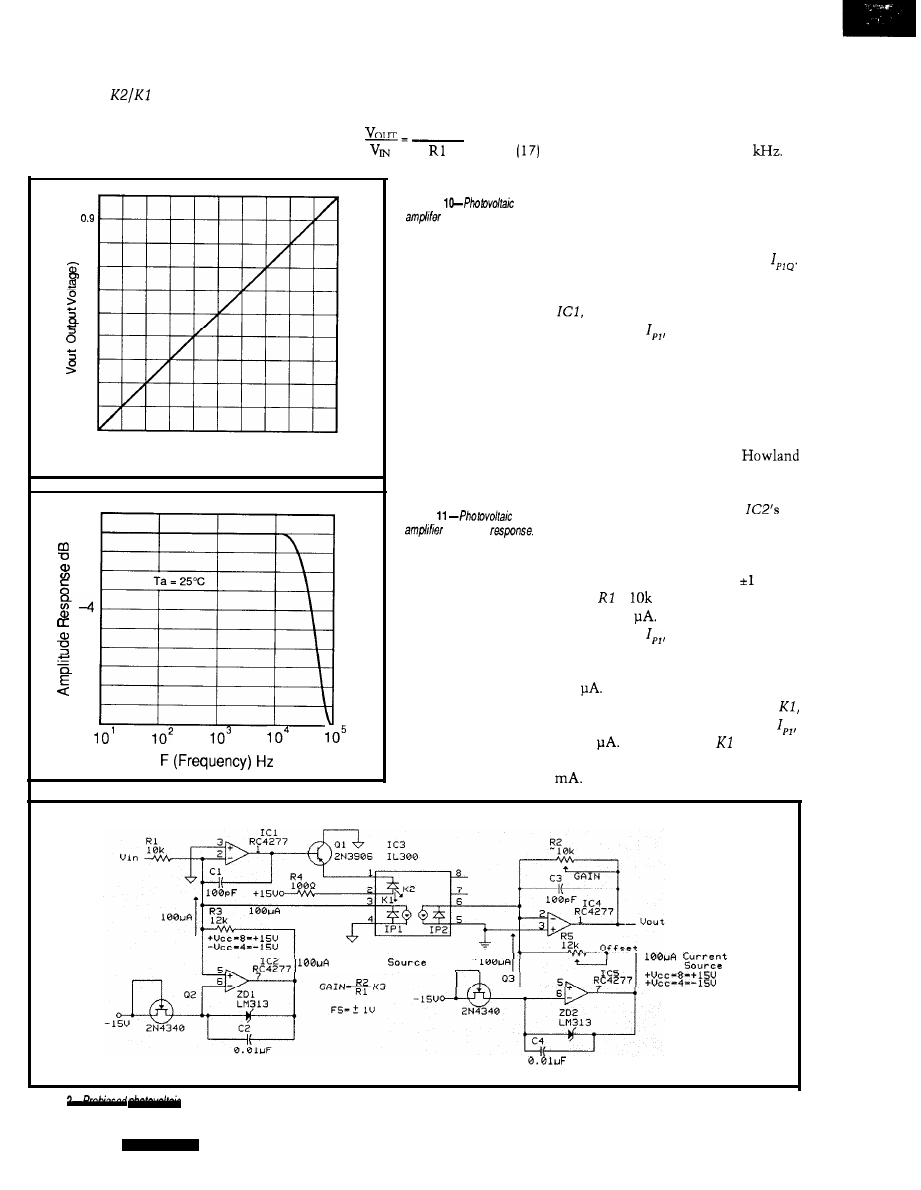
independent of the LED forward
current. The
ratio reduces to
IL300 transfer gain, K3, which
is
included in equation 14. This shows
the composite amplifier gain is equal
to the product of the IL300 gain, K3,
times the ratio of the output to input
resistors.
K3 x R2
The amplifier has the gain transfer
and linearity characteristics shown in
Figure 10. The frequency response is
shown in Figure 11. This amplifier has
1.0
0 . 6
>
0.7
0.6
0.5
0.4
0.3
0.2
0.1
0.0
a small signal bandwidth of 45
Figure 12 shows a photovoltaic
isolation amplifier with prebiased
Figure
transfer gain.
amplifiers.
The dynamic input range of the
0.0
0.1
0.2
0.3
0.4
0.5
0.6
0.7
0.9
0.9
1.0
Vin (Input Voltage) V
1
0
-1
- 2
- 3
- 5
- 6
-7
- 8
- 9
- 1 0
amplifier and the input resistor,
R 1,
set
the quiescent operation point,
The bias is introduced into the
inverting input of the servo amplifier,
and forces the LED to provide
photocurrent,
to servo the input
back to a O-volt equilibrium. The bias
source can be as simple as a series
resistor connected to Vcc. Best
stability and minimum offset drift are
achieved when a good-quality current
source is used. Figure 12 shows an
amplifier using two modified
current sources. The first source
prebiases the servo amplifier, and the
Figure
second source is connected to
frequency
inverting input which matches the
input prebias.
This amplifier is designed to
respond to a bipolar signal of V.
Given
=
results in a quiescent
point of 100
The maximum servo
photocurrent,
occurs with a
+ 1.000-V input. Under this input
condition, the photocurrent will be
200
The maximum LED current is
calculated using the the servo gain,
and maximum servo photocurrent,
of 200
With a typical of 0.007,
the maximum LED current will be 28
The OP-07’s output current must
current
Figure 1
isolation amplifier.
7 2
Issue X25
1992
The Computer Applications Journal
be boosted in order to handle this LED
drive requirement and is accomplished
by using a
PNP as a buffer
transistor between the output of
and the LED. The buffer transistor has
the added effect of reducing the
07’s thermal drift by reducing the
07 internal power dissipation and
allowing it to provide the maximum
LED current of 28
The amplifier’s output signal is a
combination of input voltage times the
voltage gain and an offset voltage. This
is shown in equations (18) and (19).
V
=
x Gain + offset
V
=
x K3 x
+ R2 x
x
To calibrate this amplifier, first
adjust the offset
resistor for Vo,,
= 0 V while the input resistor
is
grounded. Next apply a stable 1.000-V
voltage to the input and adjust the gain
resistor
for Vo,, = 1
V.
The previous circuit offers a
and AC-coupled bipolar isolation
amplifier. After calibration the output
will be zero volts for an input of zero
volts. This circuit exhibits exceptional
stability and linearity and has demon-
strated compatibility with
A/D
converter systems. The circuit’s
common mode rejection is determined
by CMR of the
CONCLUSION
The analog design engineer now
has a new circuit element that will
make the design of isolation amplifiers
easier. The preceding circuits and
analyses show the variety of isolation
amplifiers that can be designed. As a
guide, when highest stability of gain
and offset is needed, consider the
photovoltaic amplifier. Widest band-
width is achieved with the
amplifier. Lastly, the overall
performance of the isolation amplifier
is greatly influenced by the op-amp
selected. Noise and drift are directly
dependent on the servo amplifier.
The IL300 also has utility in the
digital environment. The pulse
response of the IL300 is constant over
time and temperature. In those critical
designs where LED degradation and
pulse distortion can cause system
failure, the IL300 will eliminate this
failure mode.
q
Siemens Components, Inc.
Integrated Circuit Division
219 1 Laurelwood Road
Santa Clara, CA 95054
Tel: (408) 980-4500
The IL300 is available from:
Pure Unobtainium
Tel:
Bob Krause is an applications engineer
with Siemens Components Inc.
413
Very Useful
414
Moderately Useful
415 Not Useful
task manager
intertask
memory manager
error manager
events, timing resource manager
preemptive
EASY TO USE
libraries for Microsoft C, Borland C/C++,
New Product
Zortech C/C++ and assembler
User’s Guide, and Reference
standalone, PC, and DOS platforms
task debugger
6 months free support and updates
FAST SMALL
15
max. interrupt latency
150
typical task switch
8 to 25 KB code size
Use
our
Little
and Tiny
miniature micro-
processor-based computers to instantly computerize your
product. Our miniature controllers feature built-in power
supplies, digital
serial
A/D
converters (to 20 bits), solenoid drivers, time of day clock,
battery backed memory, watchdog, field wiring connec-
tors, and more! Designed to be easily integrated with your
hardware and software. Priced from $159. Core modules
as low as $59. Low cost, interactive Dynamic
makes
serious software development easy.
Ask about our $95 evaluation kit.
Z-World Engineering
6402
Tulagi St.
Cypress CA
FAX
Microcontroller
Instant C
1724
Ave., Davis, CA 95616 USA
Tel:
(916)
753-3722
Fax: (916)
Automatic Fax: (916) 753-0618
(Call from your fax, request catalog
40
The Computer Applications Journal
Issue X25 February/March, 1992
73
DEPARTMENTS
Firmware Furnace
Practical Algorithms
From the Bench
Silicon Update
Domestic Automation
Ed Nisley
Two-Way Power Line
Communication
ontrary to what
you might suppose,
Steve really can be
lured out of town. But
guess
baby-sits his Home Control
System. Right. I get a page of X-10
module addresses, the HCS reload
sequence, and a backup diskette. I’m
supposedly prepared for anything short
of plate tectonic activity.
The day after he left on the last
jaunt, his main garage door latch
clattered onto the floor. No fried
electronics, no smoking power drivers,
not even a program bug: a piece of pot
metal with remarkable timing picked
that day to end its service life.
Oft’ the best laid plans...
X- 10 remote control modules are
much the same. They are utterly
reliable for years, then snap on at
A
.
M
. every
morning for a week, and
revert to normal without a hint as to
what changed. Steve happened to be
acquainted with this feature and
designed his original HCS to remind
the modules of their state in life every
four minutes; a
module is
reset by the next refresh command.
Elsewhere in this issue you will
find Steve’s description of Circuit
Cellar’s new generation home control
system. Ken’s doing hard work on the
supervisory controller (SC) and
command compiler, and I’m supplying
a few widgets. This column describes
74
issue
February/March, 1992
The Computer Applications Journal
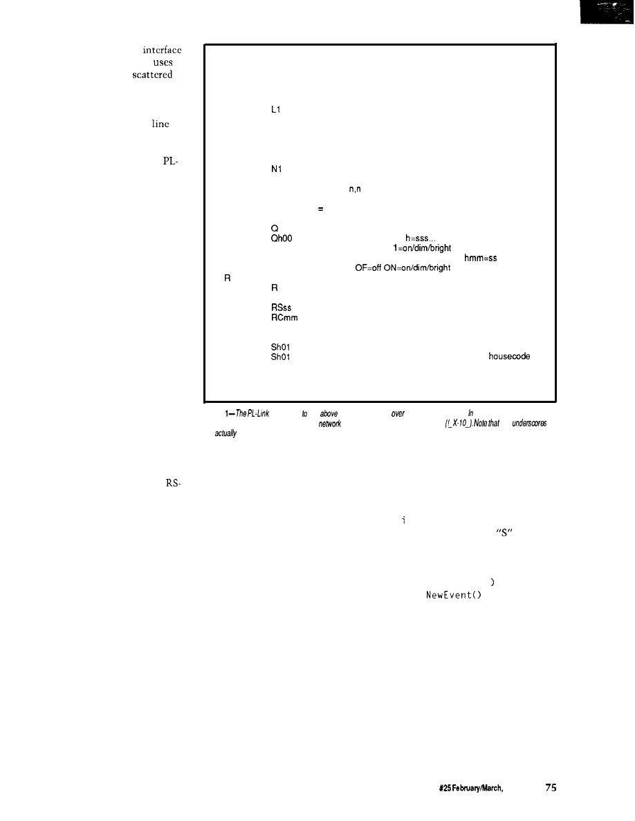
the bidirectional power line
(PL-Link) that the new HCS II
to
control the X-
10
modules
throughout the house. The PL-Link
has a simple job: convert the SC’s
orders into X- 10 command sequences
and keep the X- 10 modules in
by
resending those commands every few
minutes.
“The Smart X-10 Controller
Link” earns its moniker because it
listens to the AC line and maintains a
table of module states based on what it
hears. Turn a lamp on using a standard
X-10 control unit, and PL-Link takes
note and refreshes that lamp ON until
you (or the HCS II’s supervisory
controller) turn it off. The SC can
extract module states from PL-Link
and adjust itself to manual overrides
without special one-time program
changes, so the whole system is, if not
truly intelligent, at least dimly aware.
Because we have covered the X- 10
specs (in gory detail) in previous
issues, I will describe how to coerce C
into producing X-10 messages. The
language is Dave Dunfield’s Micro-C,
which has sprouted three new memory
models and a host of other features
since the last issue.
TAKING COMMANDS
The new HCS II supervisory
controller communicates with its
peripherals through bidirectional
485 transceivers using a single twisted
pair of wires. The peripherals are all
passive until the SC sends them a
command or status inquiry; only after
decoding a properly formatted and
addressed command may a peripheral
send anything to the SC. In fact, the
peripherals cannot echo command
characters because RS-485 communi-
cations are half-duplex.
The RS-485 messages must
include a header and a fixed-format
address field to select the appropriate
peripheral, so even though the com-
mands use plain ASCII text, they are
fiendishly difficult to type (macro keys
help!). PL-Link includes a demo mode
that eliminates the address overhead
and echoes each character as it is
received, giving you manual control
using a standard communications
program. A text file included with the
D
Dump program status (debugging use)
E
Show and clear error flags (debugging use)
Ln
Set logging mode (bit mapped)
L
report current mode
LO
disable (default)
show received X-10 messages
L2
show transmitted X-10 messages
L4
show refresh changes
Nn Set network/interactive mode
N
report current mode
NO
set interactive mode
network mode (no error messages) (default)
N2
network mode with command echo (no err msgs)
P
Report power failure status:
first digit = 1 if power is currently OFF
second digit 1 if power failed since last P command
Cl
Query X-10 module status
report all modules for all housecodes
report housecode h:
(mod 01 first)
O=off
X=not used
Ohmm
report module mm for housecode h:
X X = n o t u s e d
Set refresh period
report current period in seconds
Rmm
set period in minutes
set period in seconds
clear refresh buffer, set period in minutes
S
Send X-10 message
Shmmff
send function ff to housecode h module mm
AF
send ALL UNITS OFF command to housecode h
AN
send ALL LIGHTS ON command to
h
Shmmffrr
send function ff to housecode h module mm
function message repeated rr times
(may be strung together: Shmmff,hmmffrr,hmmff)
Figure
responds the
commands sent
the serial interface. normal mode, each
command must be preceded by the
header and controller’s address
the
are
spaces in the message sent
downloadable code shows how to
activate “human” mode.
Figure 1 shows PL-Link’s com-
mand set. There are only three really
useful commands: send an X- 10
message, query the status of a house
code or single module, and clear the
refresh tables. The remaining com-
mands are handy, but the Big Three do
most of the work.
PL-Link uses serial interrupt
handlers, ring buffers, and interface
routines similar to those I have
presented in the past and don’t require
description here. For me to say that
serial interrupts are set to low priority
allowing the high-priority power line
interrupts to occur without delay is
enough. The timer and AC line sync
interrupts require only 100-200
microseconds, so they do not cause
lost characters.
The Micro-C run-time library
includes serial port drivers, but they
are not appropriate for the task at hand
because they assume ordinary “hu-
man” serial input instead of a robot
network. Such is firmware....
Listing 1 shows the code invoked
by a “Send” command. The outer
w h 1 e loop picks off repeated X- 10
commands following the
charac-
ter, extracts and validates each set of
parameters, and sends the appropriate
X- 10 bit sequences to the power line
using the
PwrSendSeq(
function.
The Ref
function enters
the module’s ON/OFF state in the
refresh table.
A complete X- 10 transmission
consists of a house and device code to
select a particular module, followed by
a house and function code to tell that
module what to do. The house/device
and house/function messages are
normally sent twice, except for the
DIM/BRIGHT functions, which may
be sent up to 32 times. There should
be no delays between repetitions, but
there must be a delay between the
The Computer Applications Journal
Issue
1992

house/device and house/function
groups.
The
function
shown in Listing 2 translates the
house, device, function, and repeat
values into X- 10 transmission
(as I understand the rules,
anyway!). In most cases, there will be
four X- 10 transmissions for each
Link command, each with a different
bit pattern or length.
createsthebit
patterns and inserts them into a ring
buffer, which is emptied by an inter-
rupt routine that sends
each bit at the right
tory” I/O pins, the firmware also
provides for three optional LED
sink the 4.5 milliamps required to
outputs: a heartbeat to indicate the
main loop is running, an indicator that
goes on when an X-10 message is being
drive the optoisolator LED. The
sent, and a power failure indicator.
Steve’s HCS II runs from
gel
cell batteries, so the X- 10 controller is
Link board shown in the photos has a
connected to
for this
purpose.
In addition to those three
the upper trace, which triggers the 20
interrupts from Timer 0 shown on the
lower trace. There are three groups of
and when to sample the
data
three interrupts in each half cycle that
mark the beginning, middle, and end
of each X-10 data bit, and a tenth
output for received bits.
interrupt to handle “setup” functions
for the next half cycle. All of these
Photo 1 shows how the firmware
produces the right bits at the right
times. The primary synchronization
comes from the
signal shown in
time.
Before I discuss
how bits are sent, an
examination of where
the bits come from and
go to in the hardware is
necessary.
BURSTS TO BITS
AND BACK
As you can see
from Figure 2, there are
two big hardware
blocks: the
bidirectional power
Listing
command decoding uses a
switch
each single-character command. This shows
the PL-Link does in
to a
case 'S'
send X-10 command
while
handle multiple parms
=
if
syntax
else
line interface and a COMM-Link
microcontroller. You may substitute
your favorite microcontroller (with
some code changes, of course), but the
is essential. In effect, it is a
modem that converts digital data into
X- power line signals and returns
digital data when it hears a valid X- 10
command on the power line.
The TW523 provides optical
isolation between your computer
circuitry and the power line’s AC
voltages and currents. Unlike the
earlier transmit-only PL513, the
TW523 has two open-collector
outputs: in addition to the
square wave for zero-crossing synchro-
nization a new bit presents X-10 data
pulses received from the power line.
Both are open-collector transistors
driven by optoisolators, which require
external pull-up resistors. The internal
8051 pull-ups are entirely satisfactory
for this purpose.
Driving the
data input
requires a buffer transistor because an
8051 I/O bit can neither source nor
the only unit that knows when the
power goes off!
The PL-Link’s RAM and EPROM
configuration depends on the C
program’s memory model. For a
C Compact model program, the
EPROM is at OOOO-7FFF and the RAM
at
with Code and Data
spaces overlapped. I edited the start-up
code to define those addresses, but
your compiler may require different
contortions. In any event, make sure
the code matches the hardware!
So much for the machinery. Now
for the tricky part.
The key to transmitting and
receiving X- 10 messages is maintain-
ing synchronization with the AC
power line. The TW523 provides a
Hz signal that identifies both zero
crossings, but the firmware will be
interrupted only by the falling edge.
Further, there are tight specs control-
PRECISION PULSES REDUX
ling when the three X- 10 transmitted
bits must occur within each half cycle
interrupts occur every power-line
cycle, so there are 20 x 60 or 1200
interrupts per second.
During power failures the timer
interrupts free-run at about 55 Hz,
A twenty-first timer interrupt will
occur if (when?) the
input
with the twenty-first interrupt filling
disappears. A state machine triggered
by that interrupt times out after eight
in for the
signal. The rest of the
missing cycles and flags a power
failure; there must be eight consecu-
firmware is unaware of the change,
tive good cycles before power becomes
“OK” again. This feature copes with
although X-10 messages don’t go
power line frequency variations down
to 55 Hz as well as glitches without
anywhere and there is no received
flagging too many errors. The HCS SC
can find out whether the power is
data. The program in the supervisory
currently off and whether it has failed
since the last status report.
controller decides how to recover from
the failure and what to tell the X-10
76
Issue
1992
The
Applications
Journal
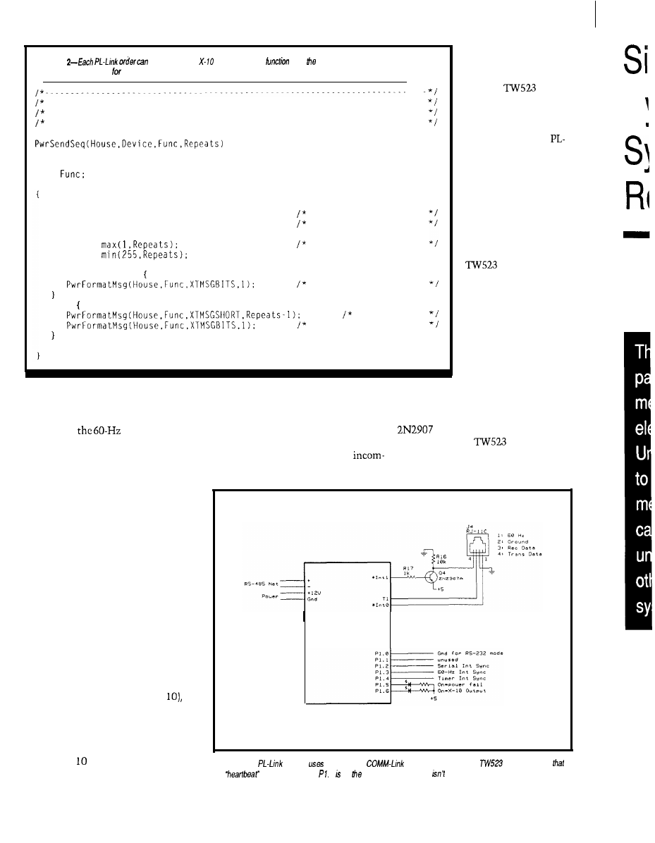
Listing
produce several
commands. This
adds
proper commands lo he
transmitter ring buffer each Send” order.
Create X-10 message given all the information...
This produces several messages with varying repeats for each part...
House. device, function are all indexes into the ACLINE tables
WORD House,
WORD Device,
WORD
unsigned int Repeats;
PwrFormatMsg(House.Device.XTMSGSHORT.1):
PwrFormatMsg(House.Device.XTMSGBITS.1);
no pause after msg
short pause
Repeats =
Repeats =
ensure good repeats
if (1 == Repeats)
ensure pause
else
no pauses
short pause here
modules when they wake up. When
power returns, the timer interrupts
will lock to
interrupt and
normal operation resume.
The interrupt handlers are written
in 805 1 assembly language using
Micro-C’s in-line assembler to embed
the code within C functions. Suffice it
to say that the code picks a bit from
the tail of the transmitter’s ring buffer
entry, sends it during each of the three
bit times, then steps to the next bit. A
variable determines how many bits are
sent in each message, and when the
bits are finished the code chucks up
the next ring entry and starts over
again.
The firmware also samples the
TW523 receiver output at the middle
of the first bit time in each half cycle,
even while transmitting a message. A
state machine finds the start sequence
(four successive half-cycles with the
otherwise invalid bit pattern 11
validates the next 18 half-cycles to
assemble a complete message, and
adds it to the head of the receiver’s
ring buffer.
COHM-Link
Module
The X- transmitter and receiver
Figure 2-The
module
the standard
as ifs basis and adds a
interface. Note
ring buffers are located in External
the
LED connected to 7 on COMA-Link board, so
shown here.
adding excessive over-
head on time-critical
parts of the code.
The
receiver is independent
of the transmitter, so
outgoing messages are
echoed back to the
Link board. PL-Link
updates its refresh table
based on both transmit-
ted and received
messages to ensure the
table always has the
latest information. The
refresh table remains
current even when the
is disconnected
or the power fails since
outbound messages
need not be echoed.
Photo 2 shows a
complete X-10 trans-
mission as seen at the
PL-Link I/O pins.
There are two pairs of
X- 10 messages: the first
two set the house and
RAM. The interrupt routines use
device and the second two set the
Internal RAM variables to speed access
house and function. Remember the
to the bits and touch External RAM
transistor inverts outgoing
only when a message is complete. This
data bits and the
presents
timing provides space for many
inverted bits to INTO; in both cases, a
ing and outgoing messages while not
“low” voltage indicates a “1” bit.
D
78
Issue X25 February/March, 1992
The Computer Applications Journal
82
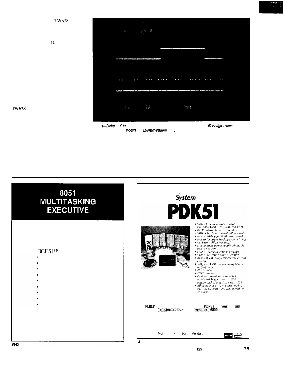
Interestingly, the
does not
behave quite like the documentation
would have you believe. The receiver
output is actually a stored copy of the
most recent valid X- message; in
effect, the TW523 records a message
and plays it back immediately,
regardless of what happens on the
power line. It cannot record and play
simultaneously, so you must send
each message twice to prevent data
loss.
For example, if you send one
house/device message (say, “N” and
“02”) followed by a single house/
function message (“N” and “ON”), the
will return only the house/
device message. X- 10 modules do not
have this restriction, so the lamp at
NO2 will turn ON. Spending a little
time sending various combinations of
messages to see how the TW523 reacts
is worthwhile.
MODELING MEMORY
The key to writing good firmware
is keeping track of your variables. The
805 1 architecture provides three
Photo
an
transmission, the primary synchronization comes from the
in be
upper trace, which
the
Timer shown on the lower trace.
address spaces in which to store
but C language syntax masks the
variables: Internal RAM, External
subtleties.
RAM, and (for constants only!) in
In addition to the program’s
EPROM with the program code. In
variables, you need RAM to hold
assembly language, you appreciate full
subroutine return addresses, save CPU
well the differences between the three,
registers during interrupts, and so
Develop Real Time Applications
FAST!
The
Executive provides:
Preemptive Scheduling
4 Priority Levels
Up to 8 Tasks
Memory Management
Message Passing
Interrupt Management
Dynamic Task Creation
Monitor Task Available
$300, No Royalties
Iota
Systems, Inc.
PH: (702) 831-6302 FAX: (702) 831-4629
POB 8987
Incline Village, Nevada 89450
The $595 Solution
to
8051
Development
The PDK51 is a fully integrated
hardware, firmware, and software
system designed to help you develop
your products quickly and cost
effectively.
All you need to use the PDK51 is
an
IBM-PC/XT/AT or compatible.
We supply the rest.
PLUS includes everything in the
plus
3 of
popular
BASIC
Call Now! 603-469-3232 or
FAX 603-469-3530
q
Binary Technology, Inc.
144
Street PO.
67 .
NH 03770
The Computer Applications Journal
Issue
February/March, 1992
Photo 2-This complete transmission
of hvo
of
messages. The
he house and
device and the second
set the house and
forth. C needs space to pass function
wonder memory models are often
arguments, evaluate expressions, and
confusing.
allocate heap storage. The memory
Micro-C now supports five
model you use tells the compiler
memory models: Tiny, Small,
where to put everything, but given the
pact, Medium, and Large. Although
sheer number of choices it is no
the names may sound familiar to
80x86 C programmers, the meanings
are not obvious. Worse, 8051 memory
models vary by compiler and “Com-
pact” may mean two different things
for two different 8051 compilers.
Remember: it’s not what you
don’t know that hurts you, it’s what
you think you know that ain’t so.
Tiny model is the simplest;
everything must fit into the 8051’s
Internal RAM. Given that there are
only 128 bytes of RAM (256 bytes in
Tiny model programs
are easily overwhelmed. Nevertheless,
the
and
COMBO
programs in
the last two columns were both Tiny
programs, even if
needed
256 bytes of Internal RAM.
Small model allows you to put
variables into either Internal or
External RAM, but keeps local
variables (those defined within C
functions] on the Internal RAM stack.
Small model may be precisely right for
your programs if you forego local
variables.
Compact model moves the local
variables to a simulated stack in
Micromint’s BRUTE-52 is the ultimate compact controller.
One look at the list of features will tell you that this
featured controller has the power to crush your most de-
manding applications:
l
CMOS
l
TTL
l
Three
counter
.
buffered
outputs
l
System Clock
l
inputs
l
Hardware Watchdog Timer
.
plus sign
converter
. Hardware Clock-calendar
channels! Samples/second!
l
.
RS-232 or
bps!
2 channels! 1.2
resolution! Selectable ranges!
l
Printer Port.
.
3.5 5.3 Inches!
bps
.
c-70°C
.
.
. Up to 56
RAM and/or EPROM
l
networked or
l
Kbii
.
ROM
BRUTE-52 offers you all these features at only
quantity OEM)
We also have a
system for $289. When
you add in Micromint’s renowned quality,
and
support, you won’t find a better value in compact control.
To order BRUTE-52, or for more information, contact:
Micromint, Inc.
4 Park Street
l
Vernon, CT 06066
Phone (203) 87
l
FAX (203) 872-2204
80
Issue
February/March, 1992
The
Computer Applications Journal
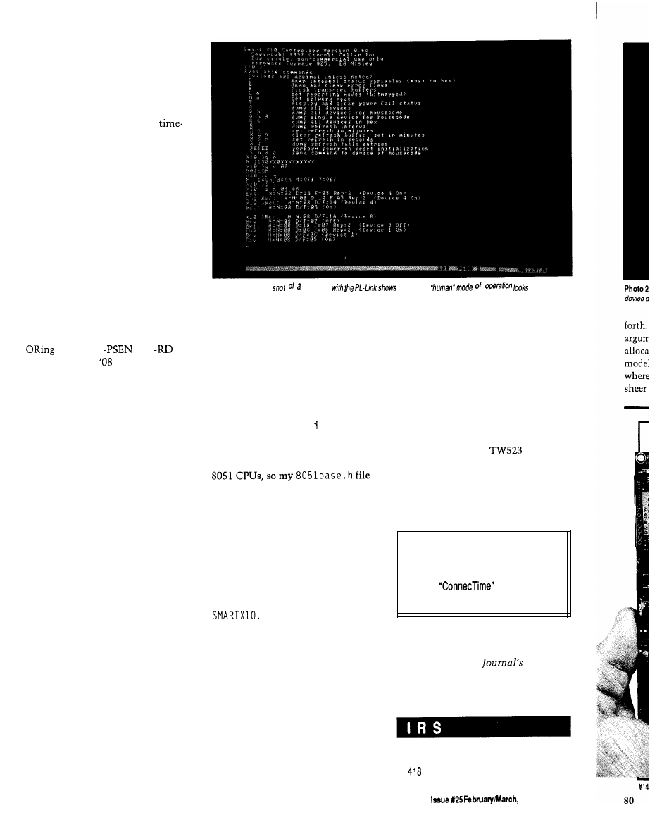
External RAM, so code using those
variables becomes larger and slower.
However, this model is a must if your
functions twiddle large character
arrays or use many local variables. The
PL-Link uses Compact model because
Internal RAM is chock-full of
critical global variables, leaving
precious little room for local variables
on the stack.
All three of these models enforce a
nonstandard restriction on your code:
any initialized variable is treated as a
constant stored in EPROM. While this
may sound like a terrible disadvantage,
your code ought to have an initializa-
tion section anyway. In point of fact,
putting true constants in EPROM
makes a great deal of sense because
they cannot be changed by a glitch or
program bug.
In addition, these models require
combined Code and Data spaces,
which is usually accomplished by
the CPU’s
and
outputs with an
gate. This process
limits the total address space to 64K
bytes total and forces RAM and
EPROM to cover different address
ranges. You can now see the reasoning
behind PL-Link’s peculiar addressing
with EPROM from 0000 to 7FFF and
RAM from 8000 to 9FFF.
Medium model is similar to Small
model, but with separate External
RAM and Code spaces. The C start-up
code copies all the initialized variables
from the Code EPROM to the Data
RAM before passing control your C
program, which can then alter the
values as needed. All local variables
must still fit on the Internal RAM
stack, so Medium model may not be
particularly useful.
Large model is the least restrictive
of the five because it uses separate
Data and Code spaces and puts local
variables in External RAM. Of course,
the resulting code can be much larger
and slower than any other model, but
it’s the only way to get 64K of Data,
64K of Code, and not run out of
Internal RAM.
In all cases, the CPU return
address stack is in Internal RAM
because that’s where the hardware
must find it. If you have allegedly
portable C code that twiddles the stack
Photo
3-A screen
session
what he
like
directly, it won’t work correctly in all
models because the Internal stack
grows up and the External stack grows
down.
Many 80x86 C compilers imple-
ment the storage class keyword n e
a r
to identify variables located within the
default segment and far for those
variables in other segments. Micro-C
slightly abuses the r e g s t e r keyword
to designate Internal RAM variables. I
prefer the former convention, even
though it is not directly applicable to
has a #de f i n e statement to replace all
NEAR variables [note the capitalization)
with register variables.
Micro-C has a separate start-up
file for each memory model. The code
defines the starting address and size for
the system’s RAM and EPROM. I also
modified the Compact start-up code to
leave room for the interrupt vectors;
the changes are detailed in
C.
SUMMING UP
SMARTXlO
as
implemented on the
PL-Link hardware can form the basis
of a powerful home control system
because it relieves the main supervi-
sory controller of the grubby details
(and critical timings) required to send
and receive X- 10 messages. It uses
either RS-485 or RS-232 communica-
tions, so you should be able to adapt it
to a wide range of systems; I’d be
interested in hearing what you come
up with.
The hex file required to create a
PL-Link EPROM can be downloaded
from the Circuit Cellar BBS. PL-Link’s
source code will not be placed on the
BBS, but may be licensed from Circuit
Cellar Inc.
The BBS files do, however, include
the complete source code for
MON X 10,
an X- 10 monitor program that reports
what it hears from a
X-10
interface over the RS-232 serial link.
MO N X 10 will show you how to create a
Micro-C program with in-line assem-
bler and bit manipulations.
Next issue: a people tracker.
q
Software for thisarticle isavailable from
the Circuit Cellar
BBS
and on Software
On Disk for this issue. Please see the
end of
in this issue for
downloading and ordering information.
Ed Nisley is a Registered Professional
Engineer and a member of the Com-
puter Applications
engineer-
ing staff. He specializes in finding
innovative solutions to demanding
and unusual technical problems.
416 Very Useful
417 Moderately Useful
Not Useful
The Computer Applications Journal
1992
81
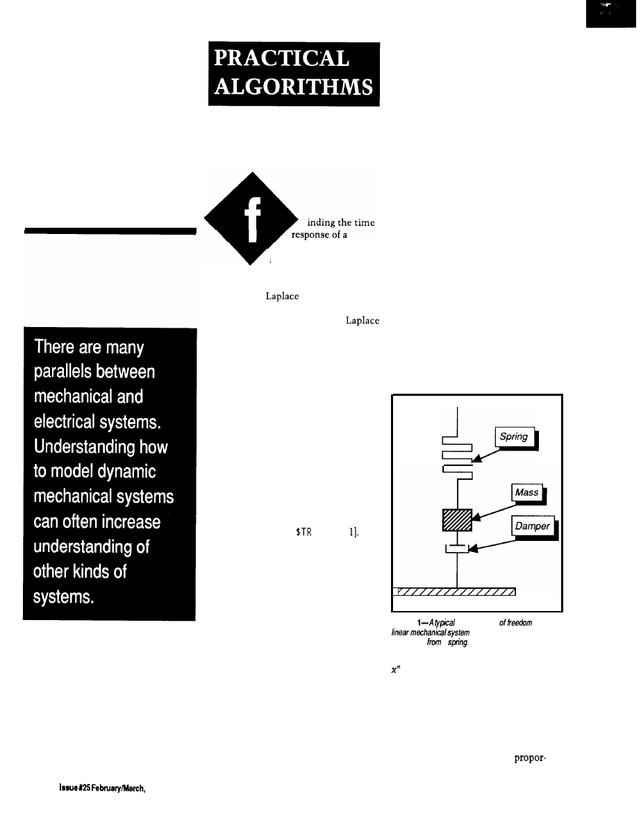
Simulating
Dynamic
System
Responses
Charles P. Boegli
mechanical system is
a simple matter of four
steps. First, determine the transfer
function of the system. Second,
calculate the
transform of the
input. Third, multiply the two to-
gether. Fourth, find the inverse
transform of the product. The transfer
function arises from physical consider-
ations of masses, spring constants, and
damping. The unit step and unit
impulse are used extensively as
“standard” inputs.
These steps are useful where the
transfer function and input can be
expressed analytically, but they serve
less well where the system is
nonlinear or the input transient is
arbitrary. When the mechanical
system has arbitrary transients, one
way to find the response is by numeri-
cally solving the differential equations.
Several FORTRAN routines are
available, among them
ES P [
Another alternative is simulating the
transient response of a mechanical
system with spreadsheets. The
response is found without solving
differential equations, and it proceeds
directly from basic and easily compre-
hended mechanical considerations.
The effects of the changes in spring
constants and damping are immedi-
ately obvious, making these solutions
unusually appealing.
Differentiating between
analysis
and
synthesis
of a system is important.
A typical synthesis is: given an
arbitrary pulse and a desired output
response, determine the transfer
function of the system to realize the
response. This problem is far more
difficult than analysis, which starts
with the input and the transfer
function and then finds the output. In
designing mechanical systems, more
often trial-and-error analyses are
repeated to obtain the desired output
than attempting synthesis. A spread-
sheet program facilitates such search-
ing, and what it lacks in accuracy it
more than makes up in rapidity and
convenience.
SINGLE DEGREE OF FREEDOM
FIXED SYSTEMS
A typical single degree of freedom
fixed linear system is depicted in
Figure 1. A mass is suspended by a
spring, with its freedom to move
controlled by a fluid damper fixed to a
support. The differential equation
describing this system’s behavior is
mx” + cx’ + kx = F(t)
in which x is the displacement of a
mass
m, c
is the damping, and
k
is a
spring constant. The quantities x’ and
Spring
Figure
sing/e
degree
fixed
includes a damped mass
s u s p e n d e d
a
refer to the first and second deriva-
tives of x with respect to time. The
driving function
F(t)
represents the
input to the system.
This equation is merely a force
summation. Its first term measures the
force needed to accelerate a mass. A
viscous damper exerts force
82
1992
The Computer Applications Journal
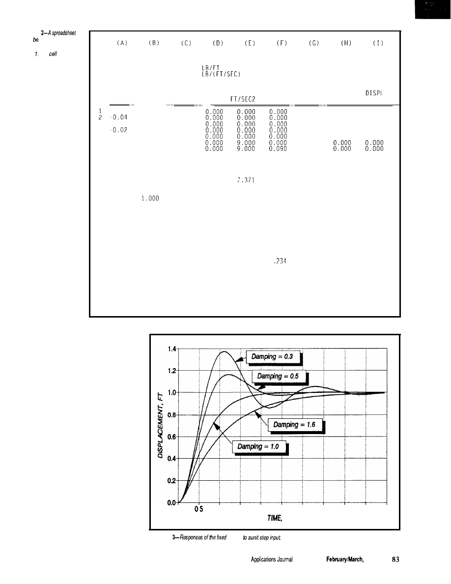
Figure
can used to simulate the
mechanical system in
Figure The
equations
used in his spreadsheet
are described in the text.
SINGLE DEGRFE OF FREEDOM FIXED SYSTEM
CHARLES BOEGLI
MASS
1.000 SLUG
MAX DISPL
1.163
SPRING
9.000
DAMPER
3.000
TIME
INP DISPL
SEC
FT
-0.05
3
-0.03
4
5
-0.01
6
0.00
7
0.01
8
0.02
9
0.03
10 0.04
11 0.05
12 0.06
13 0.07
14 0.08
15 0.09
16 0.10
17 0.11
18 0.12
19 0.13
20 0.14
21 0.15
22 0.16
23 0.17
24 0.18
25 0.19
26 0.20
27 0.21
28 0.22
29 0.23
30 0.24
31 0.25
32 0.26
SPRING
FORCE
LB
0.000
0.000
0.000
0.000
0.000
0.000
0.000
0.000
0.000
0.000
1.000
9.000
1.000
9.000
1.000
8.987
1.000
8.960
1.000
8.935
1.000
8.904
1.000
8.863
1.000
8.815
1.000
8.762
8.702
1.000
8.636
1.000
8.564
1.000
8.487
1.000
8.404
1.000
8.317
1.000
8.224
1.000
8.128
1.000
8.026
1.000
7.921
1.000
7.812
1.000
7.699
1.000
7.583
1.000
7.463
1.000
7.340
1.000
7.215
1.000
7.086
1.000
6.956
DAMPER
FORCE
ACCEL VELOCITY OUT DISPL
VEL
LB
FT/SEC
FT
PREDICT PREDICT
-0.864
8.123
-0.930
8.030
-0.770
8.165
-1.258
7.647
-1.492
-1.682
7.134
-1.898
6.864
-2.108
6.594
-2.298
6.338
-2.484
6.080
-2.663
5.824
-2.834
5.570
-2.997
5.320
-3.153
5.072
-3.301
4.826
-3.442
4.584
-3.576
4.345
-3.703
4.109
-3.823
3.876
-3.936
3.647
-4.042
3.421
-4.141
3.199
-4.234
2.981
-4.320
2.766
-4.400
2.556
0.176
0.256
0.337
0.416
0.492
0.564
0.634
0.701
0.766
0.828
0.888
0.945
0.999
1.051
1.100
1.147
1.192
1
1.274
1.312
1.347
1.380
1.411
1.440
1.467
0.000
0.000
0.000
0.000
0.000
0.000
0.000
0.002
0.004
0.007
0.011
0.015
0.020
0.026
0.033
0.040
0.048
0.057
0.066
0.076
0.086
0.097
0.108
0.120
0.132
0.145
0.157
0.171
0.184
0.198
0.213
0.227
0.288
0.001
0.310
0.004
0.257
0.007
0.419
0.011
0.497
0.015
0.561
0.021
0.633
0.026
0.703
0.033
0.766
0.040
0.828
0.048
0.888
0.057
0.945
0.066
0.999
0.076
1.051
0.086
1.100
0.097
1.147
0.108
1.192
0.120
1.234
0.132
1.274
0.145
1.312
0.157
1.347
0.171
1.380
0.184
1.411
0.198
1.440
0.213
1.467
0.227
tional to the velocity of movement, as
described by the second term, while
the third term shows a spring exerts
force proportional to its extension or
compression. So long as the system is
at rest, all the terms are static. If the
system is disturbed, then it responds
to restore equilibrium in a manner
satisfying the equation.
Imagine the mass of Figure 1 is
held in place while the far end of the
spring is moved a unit distance away,
stretching the spring and exerting force
on the mass. At time
t = 0
the mass is
released, and under the influence of
the spring and damper it seeks to
attain a new position. The equation’s
solution describes the movement of
the mass after its release. Figure 2 is
the first page of a spreadsheet simulat-
ing this problem. Although quantities
are expressed in English units [feet,
pounds, seconds), any consistent set of
units can obviously be used.
0.0
1.0
1.5
2.0
2 5
3.0
3.5
4.0
4.5
5.0
SEC
Figure
system
The Computer
Issue X25
1992
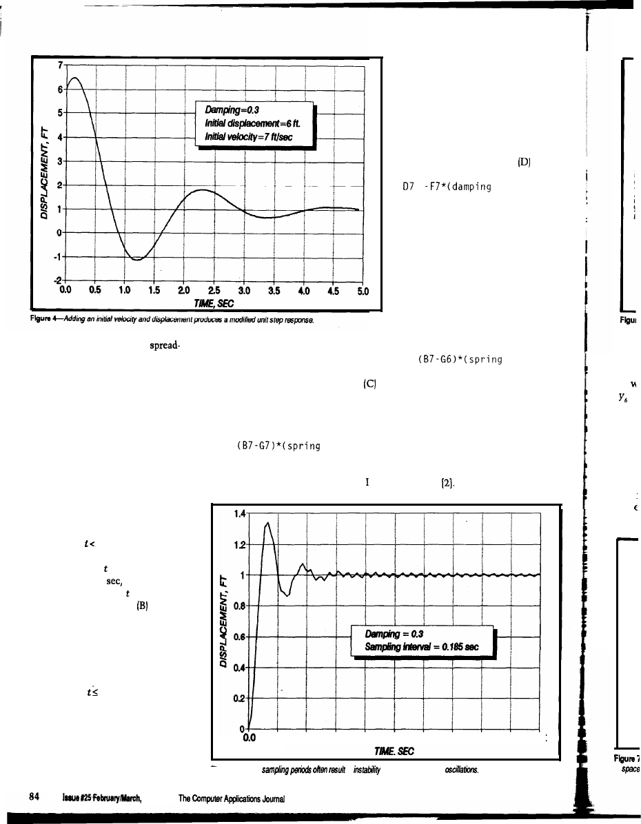
Within the body of the
Because the seventh column (G)
sheet, each row describes the accelera-
contains the output displacement
tion, velocity, and position of the mass
while column (B) lists the input
at a particular interval in time. The
displacement, the value in column
first column (A) contains the time at
is the difference between the values in
intervals short enough that accelera-
column (G) and column (B) multiplied
tions, velocities, and displacements do
by the spring constant; for instance,
not change too much (the meaning of
attempted to calculate a quantity from
the effect it will have.
Similarly, the fourth column (D)
tabulates the forces exerted by the
damper, which are proportional to the
velocity of movement of the mass
relative to the support. The sixth
column (F) will list these velocities, so
the formula used in column is
=
constant)
The negative sign is present because
the force opposes the motion. This
formula also causes a circular refer-
ence error.
You can avoid circular reference
errors in several ways. One example is
to make the time intervals short
enough that very little change occurs
during any of them. For instance, the
contents of cell C7 (for instance) are
then approximated by
C7 =
constant)
the same device being used for the
velocities.
A better way is to use a “predic-
tor” to estimate the content of a cell
from the known contents of preceding
“too much” will be clarified later). If
C7 =
constant)
cells. One predictor I favor is to fit five
such division is impossible (e.g.,
points with a third degree polynomial
because the input is not defined for
This entry in the spreadsheet results in
by
least squares and extraoolate to the
short intervals), then expedients like
a “circular reference” error because
sixth point This has the form
interpolation can fill the gaps, but
poorly interpolated values may
introduce errors into the calculation.
Several initial rows in all columns are
reserved for 0 to allow the system
to be initialized and still have an input
transient start at = 0. The time
intervals are 0.01
so the first value
for time in Figure 2 is = -0.05 sec.
The second column lists the
data for an input pulse, which I usually
enter item by item. The spreadsheet
must be longer than the total number
of data points in the input pulse
because transients will. continue for
some time after the pulse has ended.
The rows for 0 contain the initial
conditions in which acceleration,
velocity, and position are usually zero.
The third column (C) contains
instantaneous spring forces, which you
find by multiplying the extension of
20 4.0
6.0
8.0
10.0 120 14.0 16.0 18.0 20.0
Figure S-Long
in
which shows up as
the spring by the spring constant.
1992
in
is
data
Figu
and
pred
= 0,
men
five
the
force
in
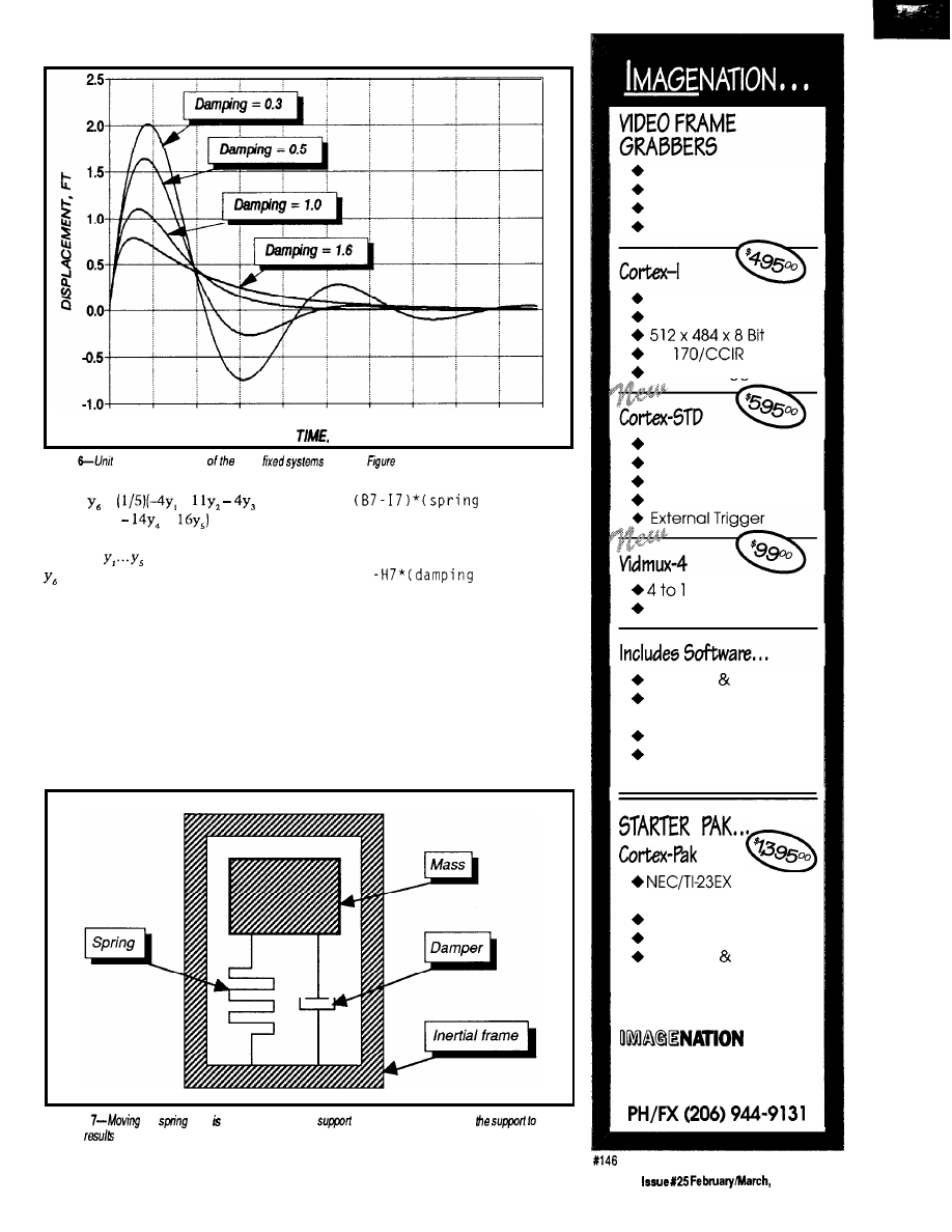
0.0
0 . 5
1.0
1.5
2 0
2 . 5
3.0
3.5
4.0
4.5
5.0
S E C
Figure
impulse responses
same
shown in
3.
=
+
+
in which
are known points and
is the extrapolation, and it requires
data points at uniform intervals.
five rows prior to
t = 0.
Column (C),
the expression for instantaneous spring
Two added columns (H and I) in
Figure 2 contain predictors for velocity
force now becomes
and displacement. Displacement
predictor calculation, which starts at
t
= 0,
requires five preceding displace-
ments and is the reason for including
C7 =
constant)
and that for damper force,
D7 =
constant)
neither of which causes a circular
reference error.
and the spring constant, will appear in
The fifth column (E) expresses the
mass acceleration. If an initial value is
the corresponding row of column (E).
placed into column (B), then the initial
acceleration, determined by that value
Subsequent rows are calculated by
Figure
We
so it attached to the same
as the damper and allowing
move
in space
in different behavior.
Simplicity
Functionality
Affordability
Accuracy
Real-Time Capture
Half Slot XT/AT
RS-
External Triaaer
Dual Video Input
Opt. XMS Mapped
Low Power Options
STD-80 or 32 Bus
MUX
Half Slot XT/AT
C Library Source
Image Capture
Utility
Tiff Utilities
“Image” Drive
Ram Disk Emulation
Camera
With Lens
9” Video Monitor
Frame Grabber
Software Cables
OEM PRICING AVAILABLE
CORP.
P.O. Box 84568
Vancouver, WA 98684
The Computer Applications Journal
1992
8 5
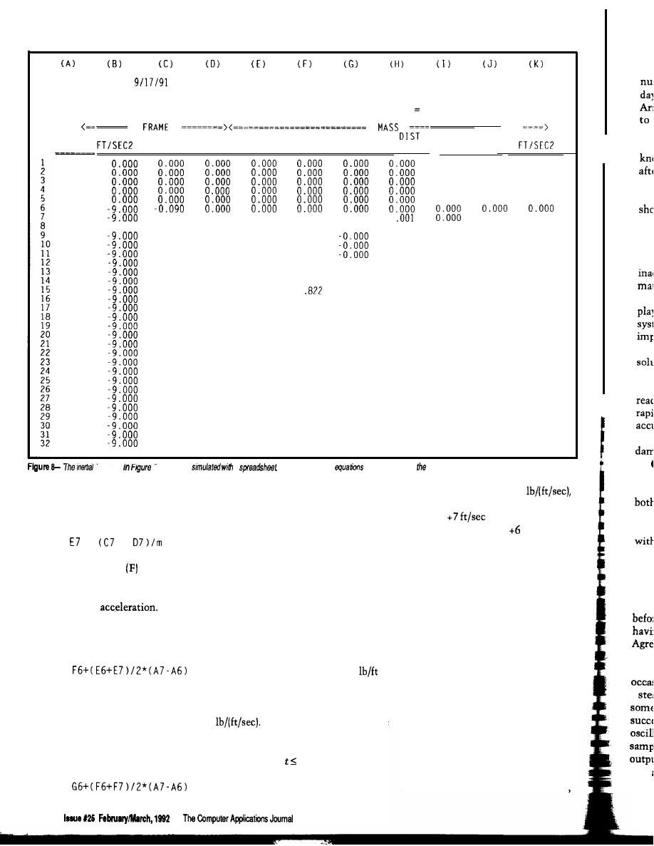
tht
wi
ren
the
ser
sin
mu
of
1
beh
tior
que
all,
nun
are
1.6,
resp
The
mea
time
posi
thos
1.37:
publ:
a
zero
elimi
GENERAL
CHARLES
INERTIAL
SYSTEM WORK SHEET
BOEGLI
MASS =
1.00
MAX REL DIST =
1.381
-13.155
0.000
SPRING CONST =
9.00
MIN MASS ACCEL =
DAMPER CONST =
1.80
MAX MASS ACCEL
TIME
SEC
-0.050
-0.040
-0.030
-0.020
-0.010
0.000
0.010
0.020
0.030
0.040
0.050
0.060
0.070
0.080
0.090
0.100
0.110
0.120
0.130
0.140
0.150
0.160
0.170
0.180
0.190
0.200
0.210
0.220
0.230
0.240
0.250
0.260
ACCEL
VELOCITY DISTANCE VELOCITY REL VEL DISTANCE REL
FT/SEC
FT
FT/SEC
FT/SEC
FT
FT
SPRING
DAMPER
ACCEL
LB
LB
0.000
0.000
0.000
0.000
0.000
0.000
0.000
0.000
0.000
0.000
0.000
0.000
0.000
0.000
0.000
-0.324
-0.324
-0.032
-0.480
-0.512
-0.060
-0.633
-0.693
-0.095
-0.782
-0.878
-0.138
-0.929
-1.067
-0.188
-1.071
-1.260
-0.245
-1.211
-1.456
-0.309
-1.347
-1.656
-0.380
-1.479
-1.859
-0.457
-1.607
-2.064
-0.541
-1.732
-2.273
-0.630
-1.853
-2.483
-0.726
-1.971
-2.696
-0.827
-2.084
-2.911
-0.934
-2.194
-3.128
-1.046
-2.299
-3.346
-1.164
-2.401
-3.565
-1.286
-2.499
-3.785
-1.414
-2.593
-4.006
-1.546
-2.683
-4.228
-1.682
-2.769
-4.450
-1.822
-2.850
-4.673
-1.967
-2.928
-4.895
-2.115
-3.002
-5.117
-2.267
-3.072
-5.339
-2.422
-3.138
-5.560
-0.180
-0.001
0.000
0.180
0.000
0
-9.000
-0.270
-0.004
-0.003
0.267
-0.000
0.004
-0.360
-0.450
-0.540
-0.630
-0.720
-0.810
-0.900
-0.990
-1.080
-1.170
-1.260
-1.350
-1.440
-0.007
-0.011
-0.008
-0.015
-0.024
-0.035
-0.047
-0.062
-0.078
-0.097
-0.118
-0.140
-0.165
-0.192
-0.221
-0.253
-0.286
-0.322
-0.360
-0.400
-0.442
-0.486
-0.533
-0.582
-0.633
-0.687
0.352
0.435
0.516
0.595
0.673
0.748
0
0.893
0.962
1.030
1.095
1.158
1.219
1.277
1.334
1.388
1.440
1.490
1.538
1.584
1.627
1.668
-0.001
0.007
0.011
0.015
0.021
0.027
0.034
0.042
0.051
0.060
0.070
0.081
0.092
0.104
0.116
0.129
0.143
0.157
0.172
0.187
0.202
0.219
0.235
0.252
0.269
-0.016
-0.022
-0.028
-0.001
-0.002
-0.002
-0.003
-0.004
-0.006
-0.007
-0.009
-0.036
-0.045
-0.054
-0.064
-0.076
-0.088
-0.101
-0.115
-0.130
-0.145
-0.162
-0.180
-0.198
-0.217
-0.011
-0.013
-1.530
-1.620
-1.710
-1.800
-1.890
-1.980
-2.070
-0.016
-0.019
-0.022
-0.026
-0.030
-0.035
-0.040
-0.046
-0.238
-0.259
-0.281
-0.304
-0.328
-2.160
-2.250
-2.340
-2.430
1.707
-0.052
1.743
-0.058
system
7 can be
a
As before, he cell
are described in text.
summing the forces acting on the body
and dividing them by its mass; the
formula is
All these formulas are copied into
with a damping force of 1.8
the remaining cells of the spreadsheet.
when the initial velocity is changed
To use the spreadsheet, enter
from 0 to
and the initial
values for the mass, spring constant,
displacement from 0 to
ft. The
and damping constant, as well as
input transient remains a unit step
initial values for mass displacement
function, so the ultimate value of the
=
+
The next column
lists mass
velocities. The velocity in any cell is
the velocity in the preceding cell
modified by the
The first
cells hold the initial velocity that,
again, may be arbitrary but is usually
zero. For subsequent cells
[column G) and velocity (column F).
You must edit the formulas to include
proper values for mass, spring con-
stant, and damping constant; the
calculation of the shock response is
automatic.
Figure 3 shows the motions of the
mass in a system composed of a mass
of 1 .O slug and a spring rate of 9
when the initial velocities and dis-
placements are zero. The curves are for
damping forces of 1.8, 3.0, 6.0, and 9.6
Plotting the responses of the
same system with other initial
conditions is a matter of changing
numbers in the 0 rows of the
spreadsheet. For example, Figure 4
represents the response of the system
output is still 1.0, but the mass settles
down to this value quite unlike it does
with zero initial values.
ACCURACY
This technique simulates the
behavior of the system from moment
to moment, calculating the behavior of
the mass as the forces exerted on it
change. That small errors in each
calculation lead to a very large error in
the final result has been known for a
long time, and has given rise to a
number of more complicated methods
of synthesis aimed at eliminating
accumulated errors.
On the other side of the spread-
sheet coin lie two facts, the first being
F7 =
The last term takes into account the
duration of the acceleration.
The last column (G) lists mass
displacements. The first entries are the
initial displacement, usually zero.
Subsequent values are found from
G7 =
86
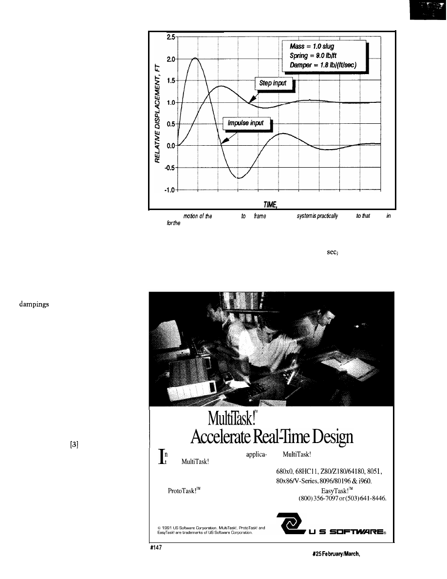
these programs carry out calculations
with high accuracy, retaining a
number of decimal places rare in the
days of mechanical calculators.
Arithmetic errors are reduced almost
to the vanishing point, and those
remaining are from the formulas
themselves. Quite often, you will
know the final state of the system,
after transients have died away, which
serves to check the accuracy of the
simulation. For instance, Figure 3
shows the problem stipulates the mass
must rest ultimately at a displacement
of 1.0.
What remains is the transient
behavior of the system in which
inaccuracies often cannot be esti-
mated. The advantage of this simula-
tion method is it reduces to child’s
play determining the behaviors of
systems complex enough to be almost
impossible to find analytically. The
question, whether an approximate
solution is better than no solution at
all, must be answered affirmatively.
Simple first-order systems are
readily solved analytically. Several
rapid checks are available to verify the
accuracy of behaviors calculated by
numerical simulation. The calculated
of the systems in Figure 2
are 0.3, 0.5, 1.0 [critical damping), and
1.6, respectively. Underdamped system
responses rise to a peak and then decay
both exponentially and sinusoidally.
The height of the first peak is one
measure of accuracy. (For systems
with critical or greater damping, the
time to reach some percentage of final
position is often used.)
For the underdamped systems,
those having a damping of 0.3 rise to
1.372 times the final rest position
before beginning to decay, while those
having a damping of 0.5 rise to 1.163.
Agreement between these figures and a
published graph appears excellent.
This method of simulation
occasionally exhibits instability when
a steady-state value is maintained for
some time. It is easy to detect because
successive values of displacement
oscillate rapidly (usually at the
sampling frequency) about the mean
output; transients oscillating about
zero are rare. Usually, you can delay or
eliminate the instability by reducing
0.0
0.5
1.0
1.5
2.0
2.5
3.0
3.5
4.0
4.5
5.0
SEC.
Figure
9-The
maw relative the
in the inertial
identical
shown
Figure 3 fixed system.
the time intervals.
time intervals. Figure 5 shows the
To give you an idea of how large
onset of instability with a sampling
the time intervals can be to obtain
interval of 0.185
however, even
accurate transient response and avoid
with this coarse interval, the peak
instability, I repeated the calculations
transient amplitude dropped only
for damping equal to 0.3 with larger
slightly, to 1.343.
Executives
a hurry to
develop real-time
executives support today’s
ions?
executives give you a
most popular microprocessors:
full set of standard system services for most
embedded processors.
Source code keeps you in control. And
our
executive lets you develop
Call for a free
information
code on the PC. No matter which target you
diskette:
choose or when you choose it.
14215 NW Science Park Drive
Portland, OR 97229
The Computer Applications Journal
Issue
1992
8 7
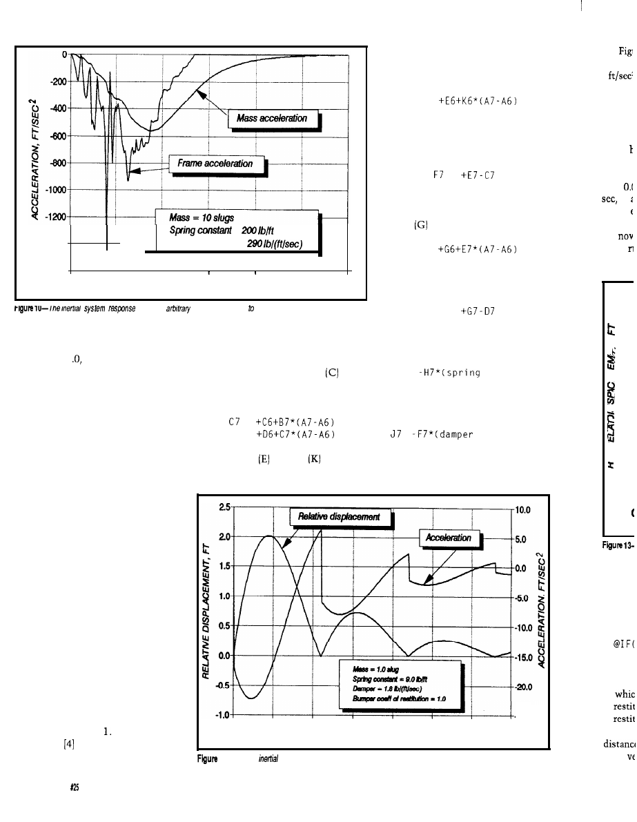
-1400
=
--
Damper constant =
\
-1600
,
I
I
0.000
0.050
0.100
0.150
0.200 0.250
0.300
TIME. SEC
to an
acceleration applied the system.
The unit impulse, a spike of
infinite height, infinitesimal width,
and area of 1 cannot be easily
entered into a spreadsheet. However,
you can find the response to a unit
impulse by differentiating the response
to a unit step. In the spreadsheet of
Figure 2, I obtained the displacement
by integrating the velocity. Differenti-
ating the displacement is pointless
because the derivative is already
available in the velocity column. The
displacement response to a unit
impulse is the same as the velocity
response to a unit step. Figure 6 shows
unit-impulse responses for the systems
used in Figure 3.
relative to the inertial frame. In this
sheet, column (A) is devoted to time,
column (B) to an arbitrary acceleration
of the inertial frame, column
to its
velocity, and column (D) to its dis-
placement. The formulas for row 7 are
=
D7 =
Columns through refer to
The last column presents the
the suspended mass. Column (E)
acceleration of the mass, found by
calculates the velocity of the mass
from the previous velocity and
acceleration using
E7 =
In column (F) the relative velocity
[the velocity of the mass in relation to
that of the inertial frame) is
=
Similarly to column (E), the
distance of the mass in found in
column
from
G7 =
while column (H) computes the
relative distance of the mass using
H7 =
In column (I) the force exerted by
the spring is
17 =
constant)
while in column (J) that exerted by the
damper is
=
constant)
SINGLE DEGREE OF FREEDOM
INERTIAL SYSTEMS
The damper in Figure 1 is fastened
to a fixed support. If it is instead
attached at the same point as the
spring, as depicted in Figure 7, the
system is not the same as that shown
in Figure 1 because displacement of
the support acts on the damper as well
as the spring. However, the system of
Figure 7 lacks any fixed supports and
can move independently in space.
system,
which t
pounds.
In t
express:
Accelerating the inertial system of
Figure 7 is the same as moving the
spring end in Figure The spreadsheet
0.0
0.5
1.0
1.5
-25.0
20
25
3.0
3.5
of Figure 8 verifies this fact by
TIME, SEC.
simulating the motion of the mass
11 -The
system response to an impulse acceleration applied to the system.
in
of
of
lated in
mass
8 8
issue February/March,
1992
The Computer Applications Journal
90
system
9
system,
set agai.
The ma
bumper
the bun
tion it
velocity
I had to
from
to
tioned
Fig:
but
of the
1.0 too
2c
1.5
1.0
0.5
0.0
4.5
-1.0
+
El
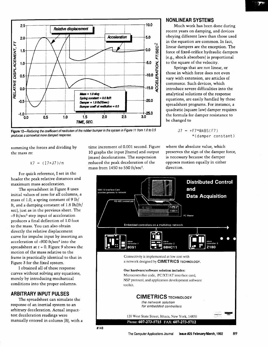
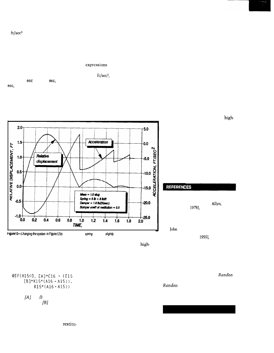
Figure 11 shows the response of a
system similar to that of Figure 9 to a
9
pulse. However, in this
system, a perfectly resilient bumper is
set against the mass at rest position.
The mass can move away from the
bumper freely, but when it encounters
the bumper going in the other direc-
tion it bounces away with the same
velocity as that with which it struck.
I had to reduce the sampling interval
from 0.01
to 0.005
starting at 2
to avoid the oscillation I men-
tioned earlier.
tion coefficient) times the frame
velocity minus (the previous mass
velocity plus the restitution coefficient
times the acceleration times the time
interval), otherwise it is the previous
mass velocity plus the (acceleration
times the time interval). As you’ve
probably guessed, setting up these
can be a headache.
The final acceleration in Figure
13, -5
represents the force of
the prcloaded spring on the mass when
the mass rests against the bumper.
Figure 12 is for the same system,
CLOSING REMARKS
but now the coefficient of restitution
Spreadsheets like those used in
of the rubber bumper is reduced from
this paper are of great utility in
1.0 to 0.5. Figure 13 is for the same
analyzing systems. You can more
SEC.
use
a different
yields a
different graph.
system, but with a preloaded spring for
which the force is 5 + 8 x (deflection)
pounds.
In the last three examples, the
expression in El6 (for example) is
rapidly write the nucleus of a
level language program to carry out the
analysis, with assurance that the
mathematical expressions and opera-
tions work properly; the spreadsheet
eliminates most of the debugging.
+
E l 5 +
in which
is 1 plus the coefficient
of restitution, and
is the coefficient
of restitution. This statement trans-
lated into English is: if the relative
distance is is less than zero, then the
mass velocity is (one plus the
I originally intended to include
two degree of freedom systems [which
as a class are more important than
single] and to also consider vibration,
which may introduce a new set of
problems. I quickly realized that the
range of possibilities opened by each
incursion into a new facet of the
technique would be a many months’
task.
With proper care, spreadsheet
simulation can be a valuable tool for
analyzing shock responses. It is
especially worthwhile with systems
that have severe nonlinearities and are
difficult or impossible to handle by
classical techniques. But where this
method appears to show an unex-
pected phenomenon, view it with
some skepticism and subject the
results to a number of tests (such as
reduction of the sampling time
interval).
On the other hand, the method
works well even when input data are
not available at fixed time intervals.
Particularly because it reduces the
calculation of shock response to a
technique understandable to any
school student, I hope it will be of
value in the development of new
devices, where the ability to deal
easily with nonlinear systems may
permit exploring a wider range of
design possibilities.
ACKNOWLEDGEMENT
The encouragement of my friend
and fellow computer enthusiast Jeff
Spray is gratefully acknowledged.
q
1. Tse, Morse, and Hinkle, Mechanical
Vibrations/Theory and Applications,
Second Edition (Boston,
and
Bacon Inc.,
Appendix C.
2. Charles P. Boegli, “Functions of
Tabulated Experimental Data,”
unpublished ms.
3.
G. Tuxal, Control System
Synthesis [New York: McGraw-Hill
Book Company,
39.
4. This spreadsheet does not employ
predictors because they do not work
well with the nonlinear systems I will
address shortly. For this reason the
sampling time intervals must often
be shorter than in the spreadsheet of
Fig. 2.
Charles Boegli is president of
Corporation in Blanchester, Ohio.
is a small company offering
services in technical computer
programming and analog circuit
design.
419 Very Useful
420 Moderately Useful
421 Not Useful
90
Issue625
February/March, 1992
The Computer Applications Journal

Does It
Come With
a Memory...
Standard?
Jeff Bachiochi
Say NO!
sn’t that what we
our kids? When
you begin to feel un-
comfortable with something, “Just say
NO.” Well, I’m feeling a bit uncom-
fortable right now. I’m unsure of a
decision I made based on conversa-
tions with a few manufacturers’ reps.
You see, what I thought was, may not
be. And if it isn’t, then it just doesn’t
make sense. You know? Let me try to
explain.
One of the problems facing both
software and hardware engineers using
microcontrollers is the limited amount
of address space available for data
collection. Whether it’s a fast sampling
rate or just logging over a long period
of time, storage space is often at a
premium. Although I might start
Unfortunately, they are heavy and
require a reasonably clean environ-
ment to perform well. Transporting
between systems is a pain because
most operating systems have their
own unique recording format.
If you use a RAM disk as a fast
storage device, you know the benefits
of the speed it has over mechanical
drives. You also know its downfall if
you’ve shut down your computer
without saving its files to either a
floppy or a fixed disk. A mass storage
device made with nonvolatile RAM
would be just the ticket for logging
data and easily transporting it between
environments.
IT’S
NOT YOUR AVERAGE
MEDIUM
Many times new products are
based entirely upon new parts. Newer
technologies produce faster, more
powerful, and (hopefully) cheaper
parts. Designing around new parts is
dangerous, especially if they are only
manufactured by one source. You can
end up with a super widget, but go
down the drain because you can’t get
the new part in any quantity, the price
goes through the roof, or worse yet, it
gets discontinued altogether.
I grumble about standards when-
ever I don’t have what I need. H
OW
many different spark plug or oil filter
wrenches do you own! Ever noticed
with 64K of space available, it
quickly gets whittled down
to
8K or 32K at best.
Disk drives are an
alternative for
logging
The Computer Applications Journal
l-The Type card is
inches wide, and
inches
thick in the
Figure
linked
ible syr
widene
and
their
monke
Th
and
The
1.0 has
tions al
hardwa
modem
more li
new
host ha
support
tion
mediur
sound I
original
slowly
it all to
here an
that
THE PI
Th
I/O
92
Issue
9 4
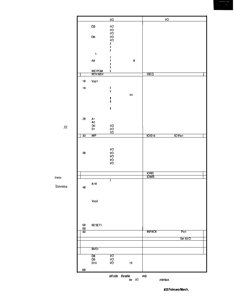
that no matter what height you set
your bookshelves to, there is always a
book that is too tall to fit? Have you
gone to the store to pick up replace-
ment watch batteries or vacuum
cleaner bags and stood there dumb-
founded, staring at the choices? Give
me a break!
My search (this time) was for
some kind of mass storage device,
similar to a 3.5” diskette, but solid
state. PCMCIA kept popping up in all
the trade journals, along with ads for
SRAM, FLASH, EPROM, ROM, and
OTP cartridges. I’d seen credit card
memories, but every manufacturer
seems to have their own connection
interface. It was a fad trying to take
root. What I needed was a little
standardization. Reps were telling me
PCMCIA was doing just that.
It seems a memory card standard
has been released. In fact, the hardware
form factors were defined back in
1985, although the first release (1 of
the standard was not published until
May, 1990. I requested information on
the released standard and started
gathering parts so I could begin
prototyping as soon as the design
popped out of the LaserJet as a sche-
matic wiring print.
SECOND THOUGHTS
In about a week a package ap-
peared on my desk. It was a
volume set of references from
PCMCIA (PC Memory Card
tional Association). At this point I
knew I’d gotten more than I bargained
for. I stared blankly at the two vol-
umes, and visions of vacuum cleaner
bags raced through my mind. When I
regained consciousness, I cracked open
volume one.
PCMCIA was formed to handle
the technical aspects of the new
memory card standard as well as the
marketing and promotional activities
to support it. Working closely with
JEIDA (Japan Electronics Industry
Development Association) ensured
compatibility between U.S. and
Japanese releases. The primary goal of
this standard was to enable system and
card manufacturers to build compat-
ible products without regard to
“what’s under the hood.” Although
Pin
Signal
Function
Signal
Function
1
GND
Ground
2
3
D 4
4
D5
5
6
D7
7
CE-1
a
A l 0
9
OE
10
Al
I
11
A9
12
13
A l 3
14
A l 4
15
16
0
17
vcc
A l 6
20
A l 5
21
A l 2
I
22
A7
23
A6
24
A5
I
25
A4
26
A3
I
27
A2
I
I
29
I
30
Data bit 3
Data bif 4
Data
bit 5
Data bit 6
Data bit 7
Card Enable
Address bit 10
Output Enable
Address bit 11
Address bit 9
Address bit
Address bit 13
Address bit 14
Write Enable
Ready/Busy
Programming
Supply Voltage 1
Address bit 16
Address bit 15
Address
12
Address bit 7
Address bit 6
Address bit 5
Address bit 4
Address bit 3
Address bit 2
Address bit 1
Address bit 0
Data bit 0
Data bit
1
Data bit 2
Write Protect
Ground
0
Interrupt Request
31
32
D2
34
GND
0
0
is 16 bit
35
GND
36
CD1
37
D l l
D12
39
D13
40
D14
41
D15
42
CE2
Ground
0
Card detect
Data bit 11
Data bit 12
Data bit 13
Data bit 14
Data bit 15
I
Card enable
43
RFSH
I
Refresh
44
RFU
Reserved
I
IO Read
45
RFU
Reserved
I
IO Write
46
A l 7
Address bit 17
47
I
A19
I
49
A20
I
50
A21
I
51
vcc
52
53
A22
I
54
A23
I
55
A24
I
56
A25
I
57
RFU
Address bit 16
Address bit 19
Address bit 20
Address bit 21
Programming
Supply Voltage
Address bit 22
Address bir 23
Address bit 24
Address bit 25
Reserved
Card Reset
2
WAIT
RFU
61
REG
62
BVD2
63
64
0
Extend bus cycle
Reserved
0
Input
Acknowledge
I
Register select
REG
I
Reg
Enable
0
Battery voltage
SPKR
0
Audio Digital
detect 2
Waveform
0
Battery voltage
STSCHG
0
Card Statuses
detect 1
Changed
Data bit 6
65
Data bit 9
66
Data bit
67
CD2
0
Card detect
GND
Ground
Figure 2-The signals on the
of
are found
on the original memory card interface. The signals
on the
right
side are those added or changed an and memory card
The Computer Applications Journal
Issue
1992
9 3
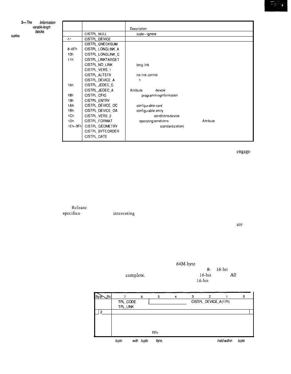
Figure
Card
Structure is a
linked
list of data
called
Code
Name
0
2-7
12h
13h
14h
15h
17h
40h
41h
Null
The device-information tuple (Common Memory)
1
(Reserved for future, upward-compatible versions of the device-tnformation tuple.)
(Reserved for future, incompatible versions of the devcie-information tuple.)
The checksum-control tuple
The long-link control tuple (to Attribute Memory)
The
control tuple (to Common Memory)
The link-target-control tuple
The
tuple
Level version/product-information tuple
The alternate-language-string tuple
Memory
informatron
JEDEC
for Common Memory
JEDEC programming informatron for Attribute Memory
The
tuple
The
tuple
Other operatrng
information for Common Memory
Other
device information for
Memory
(Reserved for future
The Level-2 version tuple
The format tuple
the initial focus was IBM PC-compat-
ible systems, the spectrum has
widened to include all computer types
and noncomputer consumer products.
Sounds like these people have
their act together. So where’s the
monkey wrench?
The two-volume set I received was
Release 2.0, issued September
199 1,
and along with it were a few surprises.
connection system, and qualifying test
parameters. All cards are 3.37 inches
long by 2.126 inches wide. The Type I
card is 0.065 inches thick. The Type II
card is slightly thicker, 0.095 inches in
the substratum [Figure 1). Other
physical standards include labeling
specs and an optional WP (write
protect] switch and battery location.
Socket contacts are used on the
to ensure proper insertion and
ment.
Mechanical performance specs
include a guaranteed number of
insertions, insertion and ejection
forces, vibration and shock immunity,
contact resistance, and current
carrying capacity. Environmental
performance specs include resistance
to moisture, shock, temperature,
The Electrical Specification of
cards, while the host connector uses
chemicals, electrical discharge, X-rays,
1.0 has been altered. New
pins. The
part of the host
ultraviolet light, and electromagnetic
tions allow the cards to contain
connector’s design is the length of the
fields. An interesting note here: “harsh
hardware other than memory (e.g., fax,
modem, or other I/O devices). The
interface is beginning to look more and
more like a PC’s expansion slot. The
new I/O devices can even execute code
directly from within, providing the
host hardware implementation
supports it. Does any of this informa-
tion sound familiar? I thought it was
supposed to be a universal interchange
medium. These higher level functions
sound processor specific to me. What
originally was a simple beauty is
slowly turning into a complex beast. Is
it all too much? Are you feeling a bit
uncomfortable? Let’s back up a bit
here and briefly look at the three parts
that make up the PCMCIA Standard.
THE PHYSICAL STANDARD
pins. There are three lengths used, and
they sequence the connections
whenever a card is inserted or re-
moved. The longest pins are power and
ground, which ensure the card is
powered prior to applying signals to
the card’s I/O connections, the second
length pins. Finally, the shortest pins
are engaged, which signal to the host
that insertion is
Card guides
built into the host connector are keyed
environment” is defined as no
conditioning or humidity control.
Hooey, I wouldn’t want to work in a
place like that!
THE INTERFACE STANDARD
The PC Card interface features a
address space (AO-A25)
using either an or
data bus.
As in other
systems,
is not
used with
words because each
This section defines the memory/
I/O card’s physical dimensions, the
Figure 4-Each
begins
a
code
which defines the type
of
information
the
block
0
CISTPL-DEVICE (Olh) or
1
Link to next tuple (at least m-l)
Device Info 1 (2 or more bytes)
Device Info 2 (2 or more bytes)
(etc.)
Device Info n (2 or more bytes)
m
(marks end of device info field)
94
Issue
X25
February/March, 1992
The Computer Applications Journal
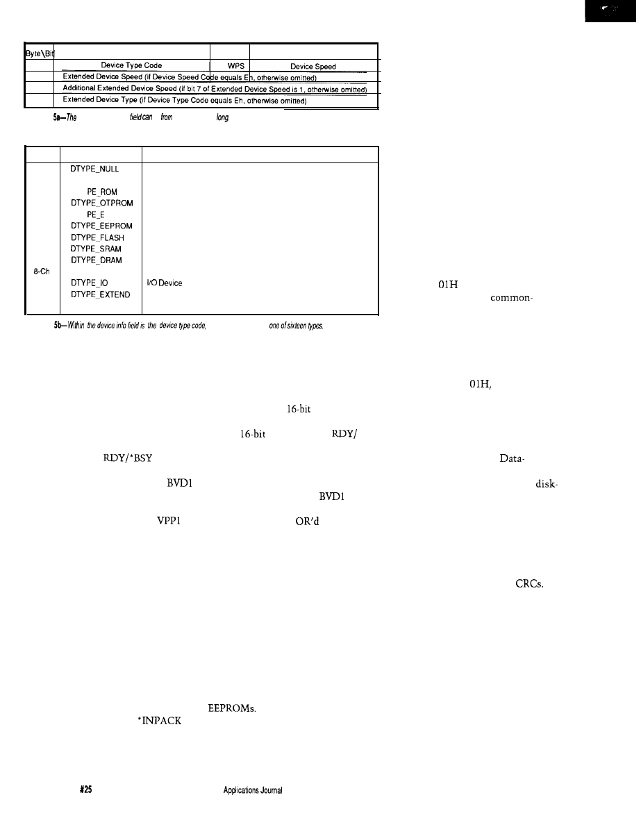
Figure
device info
be
one to low bytes
Code
Name
Meaning
0
No device. Generally used to designate a hole in the address space.
If used, speed field should be set to 7h.
1
DTY
Masked ROM
2
One-time programmable PROM
3
DTY
PROM
UV EPROM
4
EEPROM
5
Flash EPROM
6
Static RAM (JEIDA has nonvolatile RAM)
7
Dynamic RAM (JEIDA has volatile RAM)
(reserved for future use)
D h
Eh
Extended type follows
Fh
(reserved for future use)
Figure
which defines
address consists of two bytes, one at an
even address and one at the next odd
address. Two
l
CE (card enable) inputs
control the width of the data bus. If
the host uses one ‘CE, the data bus is
defined as eight bits wide.
l
OE (output
enable) and *WE (write enable) control
the direction of data flow to and from
the memory card.
signal
informs the host when the memory
card is ready for the next access.
and BVD2 reflect the status of the
backup battery and the validity of the
data within the memory card.
and VPP2 are the programming voltage
inputs for cards requiring a supply
other than VCC. You may have seen
some ads recently for a Maxim chip
that provides this supply from 5 V.
Figure 2 shows all the pin definitions.
Five pins designated as reserved on
Release 1.0 have been defined for
Release 2.0. RESET clears the card’s
configuration options, returning it to
the default power-up state. *WAIT
delays the completion of a memory
access or I/O cycle in progress. ‘IORD
and
l
IOWR signals handle data
transfers after the host has configured
the card as an I/O device.
(input acknowledge) signals the host
that the card can respond to an I/O
read cycle presently being addressed.
Four pins previously defined in
Release 1.0 can be redefined by the
host in Release 2.0 by writing to the
configuration register. WP becomes
l
IOISl6 (I/O is a
port] and
informs the host that the I/O card can
handle
data transfers.
l
BSY becomes
l
IREQ (interrupt
request) and requests the host to
perform a software service. BVD2
becomes
l
SPKR, a source of digital
audio waveforms. Lastly,
becomes ‘STSCHC (status changed),
which indicates the
conditions of
all the original signals now redefined
by the host and presently only avail-
able through the cards status register.
All memory device types are
supported. In addition to the common
memory or I/O address space, a
separate attribute memory area can be
selected for card identification pur-
poses. Not all memory cards presently
under production have this attribute
memory used for card configuration,
and there are some still unresolved
issues that deal with the programming
specifications of EPROMs and
THE SOFTWARE STANDARD
In order to support many incom-
patible data-recording formats, a
metaformat hierarchy was developed.
As of Release 2.0, five layers have been
defined from the simplest (0) to the
most complex (4). Layer 0 specifies the
interface characteristics but does not
require any configuration information.
The Basic-Compatibility Layer 1
cards must have attribute memory
containing some primary information
about the card’s size, speed, and type.
This data is recorded using a Card
Information Structure (CIS) starting at
address 0 in the attribute memory.
The CIS is a variable-length linked list
of data blocks called “tuples” [see
Figure 3). Each tuple begins with a
“tuple code byte” [Figure 4) which
defines the type of information held
within the tuple block. For instance,
tuple code
describes device
information about the
memory space used in the card. The
second byte of each tuple is an offset
pointer to the next tuple and in doing
so implicitly defines the length of the
tuple. The remaining bytes of the tuple
contain pertinent information. In the
case of tuple code
this informa-
tion would be in a device type and
speed description byte [up to four bytes
for some nonstandard device descrip-
tions), followed by a device size byte
(see Figures 5 and 6).
Layer 2 specifies the
Recording format, which falls into one
of two categories. The first is the
type format in which data blocks are
formed (like disk sectors) and blocks
are written and read as a whole. The
second is the memory-type format
where each byte is directly address-
able. As with disk-type formatting,
block data checking can be imple-
mented using checksums or
Tuple codes for Layer 2 start with 40H.
The Data-Organization Layer 3
defines how the data in a particular
partition is organized. It may contain a
DOS or other OS-type file system. It
may be a memory-type or an applica-
tion- or vendor-specific file system.
This layer uses tuple 46H and is
intended to help the host choose the
appropriate file system. ASCII text
descriptions of the organization are
implemented allowing the host to
notify the operator of the card’s file
system even if it is not supported.
96
Issue
February/March, 1992
The Computer
Layer 4 describes the
Specific standards, which are an
interchange format for all cards
formatted with a DOS FAT-based file
system, a standard for directly execut-
able programs, and a way of interpret-
ing older cards not using CIS. The
interchange format would ensure free
interchange of information between
DOS systems as long as they are
supported, but were not limited to,
this basic format. The basic format is
defined as a disk-type format of
byte blocks with no error checking.
Two types of support are defined for
the directly executable XIP (execute In
Place) programs: the LIM 4.0 standard
and the 386 extended-addressing mode.
To ensure the older memory cards not
supporting the attribute space or CIS
are still useful, a procedure is defined
for interpreting what is found on a card
and using the interchange format as a
minimal foundation.
THE END (OF VOLUME ONE)
OK, everyone take five.. has your
head stopped reeling? At this point I
know much more than I need to or
kind prepared for a product likely to
even want to. I was originally
see an early death.
with the possibility of
For those of you who are curious
ing in a device that could be extinct
as to what’s in volume two: it provides
tomorrow. After having digested
the software developer with enough
volume one, I feel comfortable
information to create a “Socket
ing this reference material isn’t the
Services” handler specific to the
X-10
DEVELOPERS KIT!
AT
LAST !! Now you can TRANSMIT RECEIVE X-10 COM-
MANDS under control of YOUR
application program.
We
supply you
with
the I-O SOURCE CODE. Be
up and running in
!!
Write your own CLIPPER/BASIC
program. We also have complete
application
packages. Shipped within 24 hours worldwide.
Phone our BBS for complete pricing and details.
Each
Kit
contains:
* X-10 TW.523 Transceiver
*
Serial OR Parallel
1
Interface
*
Microsoft/Turbo C I-O
* 6 foot cable
* Technical Reference Manual
DEALER INQUIRIES WELCOME
q
LOS ANGELES*TORONTO
VOICE 416-294-6473
BBS 416-471-6776
Cross-l 6
XDASM Cross-Disassembler:
Both MS-DOS products include support for ALL
of the above processor families.
EPROM emulators and Forth compilers too!
‘Request our catalog.
Credit cards are billed in Canadian dollars (CN$).
Canadian residents please add 7% G.S.T.
153
The Computer Applications Journal
issue X25
1992
9 7
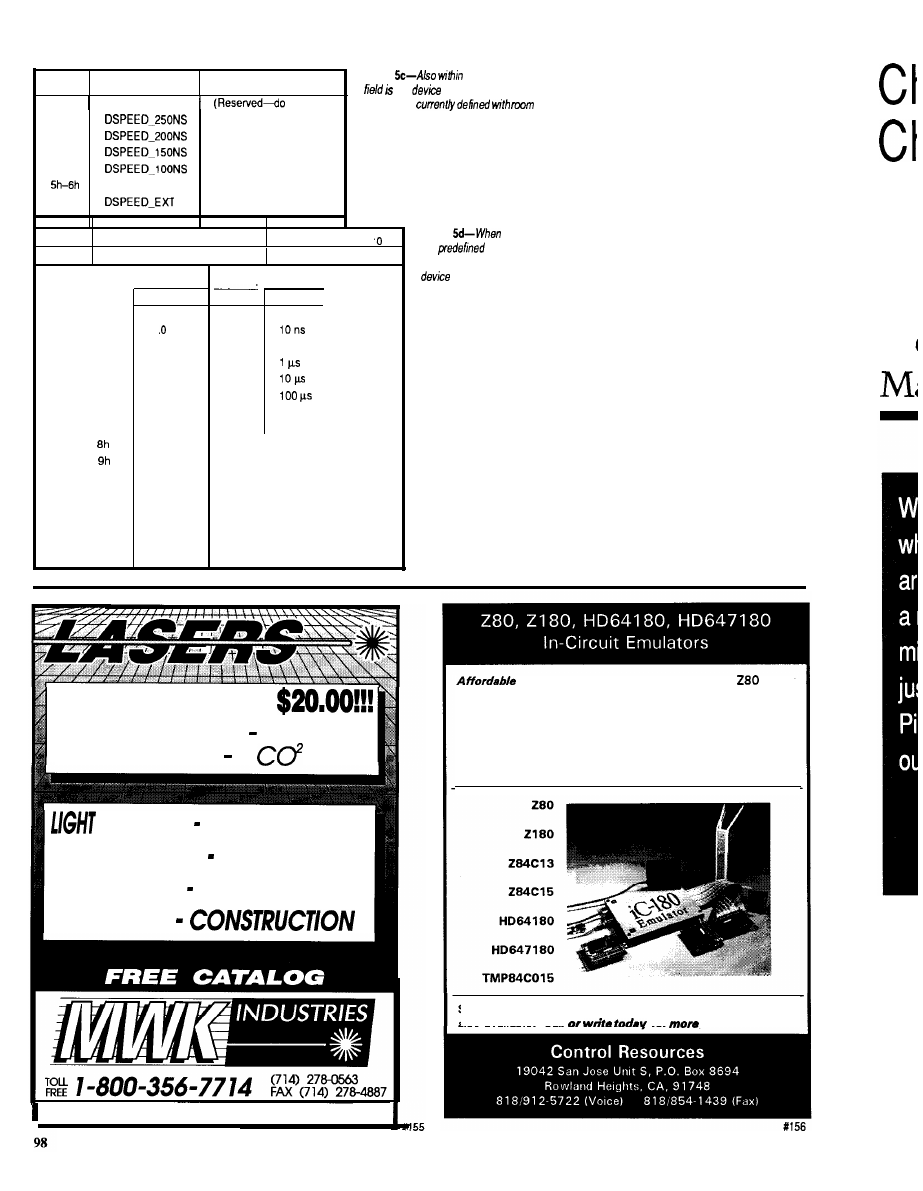
Code
Name
Meaning
Oh
not use)
l h
2h
3h
4h
7h
250 ns
200 ns
150 ns
100 ns
(Reserved)
use extended speed byte
Figure
the device info
the
sped. Four popular
speeds are
for more.
7
EXT
6
5
4
3
2
1
Speed Mantissa
Speed Exponent
Code
Oh
l h
2h
3h
4h
5h
6h
7h
Ah
Bh
Ch
D h
Eh
Fh
Mantissa
Meaning
Reserved
1
1.2
1.3
1.5
2.0
2.5
3.0
3.5
4.0
4.5
5.0
5.5
6.0
7.0
6.0
Exponent Part
Code
Oh
l h
2h
3h
4h
5h
6h
7h
Meaning
1 ns
100 ns
1 ms
10 ms
Figure
none of
the
device
speeds apply, an extended
speed may be
defined.
system’s hardware interface. This
volume will allow you to develop
higher-level software without regard
to the system-specific hardware.
Is my fear without foundation? I
thought I was getting a standard
interface that would accept memory
cards of differing types and sizes. What
I actually got was a functionally
expanded interface with specifications
requiring expanded software support to
identify and implement anything
imaginable. My plans for these
memory cards do not include fancy
formatting and file handling capabili-
ties, although they could be imple-
mented. At this point, I am satisfied
with a simple sequential-access
nonvolatile mass-storage device.
Present SRAM cards top out at about
5 12K bytes, but I can take advantage of
every new device size as it’s released
by designing with the PCMCIA
interface standard.
CREATING A BIT BUCKET
I know a logging device of such
capacity will be handy in future
LASERS FROM
HELIUM NEON ARGON
DIODE
SHOWS EXPERIMENTS
LEVELING POINTERS
CUTTING HOLOGRAPHY
ALARMS
198 LEWIS COURT, CORONA, CA 91720
state-of-the-art in-circuit emulation for
family
processors. increase your productivity with features like:
l
Symbolic and C Source Level Debugging
l
Pull-Down Menus and Command Line Interface
l
Complete Context-Sensitive Help
l
Real Time Emulation up to 12 MHz
l
Serial Interface works on any PC, even on laptops.
Satisfaction guaranteed with a risk free 15 day trial. Rentals
also available.
Call
far
information!
Le
M
Issue625 February/March, 1992
The Computer Applications Journal
100
7
6
5
4
3
2
0
of address units 1
Size Code
Code
Units
Max Size
0
512 bytes
16K
1
2K
64K
2
256K
3
32K
4
126K
4M
5
16M
6
2M
64M
7
Reserved
Reserved
Figure
he device
following
device
a device
size
situations, so it must be as universal
as possible. Because simplicity is
paramount, only four modes of
operation are necessary: serial record
and playback, and parallel record and
playback. Using serial and parallel
interfaces will allow this device to be
used by most computers or controllers.
The serial modes will be of a fixed data
rate (configured in software) with no
handshaking; just a serial stream of
data limited only by the character
transmission speed. The parallel
modes make use of strobe and ac-
knowledge signals to handshake the
data into or out of the system. Ini-
tially, there will be no provision for
recording multiple files on one
memory card. All data is simply
streamed contiguously into
(or out
of)
the bit bucket (memory) until the
system is turned off or the last avail-
able address is accessed.
Next time we’ll look at the “Bit
Bucket” in detail. I’ll define both the
hardware and software necessary to
collect mass quantities of data using
the PC Card memory devices. At least
now I have the confidence to say
“Yes” to the use of the physical and
interface standards. As far as the
software standard goes, let’s run it up
the flagpole and see who salutes.
PCMCIA
1030B East Duane Ave.
Sunnyvale, CA 94086
(408) 720-0107
Jeff
Bachiochi (pronounced
AH-key”) is an electrical engineer on
the Computer Applications
engineering
staff.
His background
includes product design and manufac-
turing.
422
Very Useful
423 Moderately Useful
424 Not Useful
Take it easy on
cargo with a custom Cabbage Case
built to the exact dimensions of your equipment.
Take it easy on your back
with our extension handle
and tilt wheels options.
Take it easy on your
wallet. Let Cabbage Cases
show you how easy it is to
save money on quality, custom-built road cases that make
shipping and traveling with your valuable cargo safer and
easier.
Prices quoted over the phone.
Call
today.
Basic Compiler._
*Soothes assembly and C irritation
_ _
relief of time and
budget headaches
strength error
handling
affordable cure for long
code winters!
Fast integer
BASIC-52 or stand-alone
outstanding technical support.
DS5000 extensions
$149
Assembly Language Toolkit $149
FAX:
The Computer Applications Journal
issue X25
1992
9 9

Cheap
Chips
Tom
Lean and
Mean PIC
Machines
ne of the first
things an aspiring
marketer learns is to
carefully. As a junior chip peddler
consultant), I remember
being told that “cheap” was a word to
be avoided. Period. Pick your euphe-
mism [“cost sensitive,” “high vol-
ume, “cost over performance”) but
for heaven’s sake, not “cheap”!
Along the same lines, simply
stating your product’s features is
considered amateurish. You must
instead relate the “benefits” that will
accrue to those customers wise enough
to choose you over competitors. With
apologies to Woody Allen, the ulti-
mate sales pitch is something like:
FEATURE: Super-duper
Thru Look-ahead Pipe-dream
BENEFIT: you a) will be loved
and will never die.
Gee, where do I sign.
Maybe I’m burned-out from the
ever-escalating hype permeating the
high-tech biz, but now is time for a
new era of glasnost marketing. I want
to see a data sheet like:
*Faster than a bat out of hell!
*Easier to use than a politician!
*Cheap!
*Cheaper!
*Cheapest!
Here are some chips from Micro-
chip Technology that fill the bill.
PIC AND CHOOSE
Let me just say up front, continu-
ing with my no-bull approach, the PIC
series has what are probably the
cheapest micros around. I’m talking as
little as $2 in volume for a complete
OTP (One-Time Program; i.e., EPROM
in a no-window package) micro with
RAM, EPROM, and I/O.
Many times, I have been faced
with the need for a little piece of logic
to perform some fairly mundane task
many times. Usually, the choices
boiled down to either wiring up a few
or using one of the popular
or
micros.
The problem is often neither
approach is ideal. The TTL-gates
approach may be best for high-volume
applications (or for those who agree
with our illustrious leader, Steve
Ciarcia, when he says, “my favorite
programming language is solder”), but
wire-wrapping and debugging more
than a few boards quickly becomes
tiresome. Furthermore, you’re faced
with diving back into the rat’s nest
when you change your mind
bly] about how it should work.
The classic
micro may be the
easiest approach, but it can be expen-
sive. A “single-chip” micro was
traditionally either ROM based (i.e.,
minimum feasible order size is
thousands) or windowed EPROM
(expensive; e.g., $10 for an 8748).
Another alternative is using a
“non-single-chip” micro, with
cost external RAM and EPROM, but
then I’m back to the wire-wrapping
blues (or more often than I care to
admit, just throwing a $100
board computer at what should be a $5
application).
Admittedly, recent technologies
have closed the gap. On the gate side,
can easily consolidate 5-10
Meanwhile, the classic
EPROM-based single-chip micros are
beginning to appear in OTP versions at
lower cost.
Despite this convergence on the
needs of low cost and volume applica-
tions, these approaches always leave
me feeling a little uncomfortable about
the waste involved because I like to
squeeze every bit of functionality out
of a given technology. The gates
approach is often speed overkill (i.e.,
you don’t need a
PAL to
toggle an LED) while the micro
100
issue
1992
The Computer Applications Journal
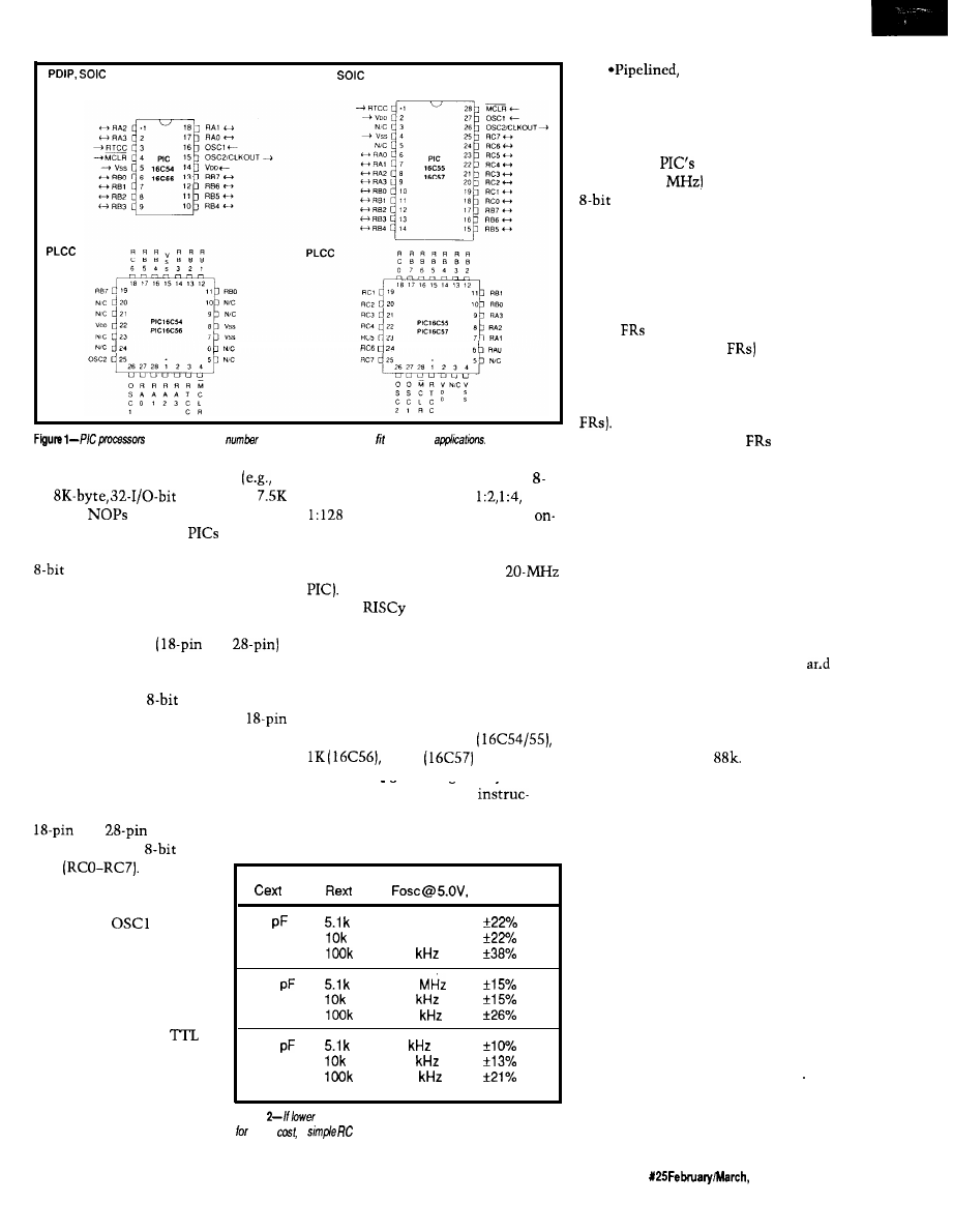
PDIP,
CERDIP Window
CERDIP Window
are available in a
of configurations
that a range of
approach is complexity overkill
an input that can clock an on-chip
an
micro with
bit counter [with optional
. . . .
bytes of
and 24 no connects).
prescaler). Alternatively, the
Read on to see how the
uniquely
chip counter and prescaler can be
fill the gap between gates and regular
micros.
CHEAP RISC
Figure 1 shows the pin-outs for the
two basic versions
and
of the PIC. Right away the dual
personality of the chip becomes
apparent; it is an
micro in small
gate-like package (especially the
DIP version). Why pay for more if you
don’t need to?
With so few pins, explaining their
driven by the internal clock divided by
four [for example, 5 MHz for a
The
nature of the PIC
becomes clearer moving on-chip
(Figure 3). Let me check off some of
the traditional RISC criteria against
the PIC.
*Fixed Length Instructions: Yep.
Every PIC instruction is 12 bits, and
different models offer 512
or 2K
instruction
capacity. Programming is easy because
function becomes blessedly easy. Note
there are only 38 different
the only I/O difference between the
tions, which is about as reduced as
and
versions is the latter
possible.
has an additional
I/O
port
In addition
to the general-purpose I/O
lines, MCLR’ is a reset
input while
and
0SC2 are the CPU clock
lines. The oscillator is
unique because it can
accept a simple RC (Resis-
tor/Capacitor) as well as
traditional crystal or
clock source. Save money
by using the RC option if
you’re willing to accept less
speed and accuracy as
shown in Figure 2. RTCC is
25°C
20
3.33 MHz
1.85 MHz
189
100
1.18
668
67.8
300
46
254
25.1
Figure
speeds and less accuracy are acceptable tradeoffs
lower
a
circuit may be used in p/ace of a crystal.
Single-Cycle Execu-
tion: OK, with the understanding that
a single cycle is four clock periods [as
shown in Figure 4). With a two-level
pipeline (fetch and execute over-
lapped), the
“5-MIPS” perfor-
mance (at 20
leaves most other
micros eating dust.
*Load/Store: The PIC fulfills this
most fundamental of RISC precepts,
subject to a little handwaving. All PIC
instructions reference “W,” a File
Register (FR), or both. In one interpre-
tation, W is a type of “accumulator”
while
(the ‘54, ‘55, and ‘56 offer 32
while the ‘57 offers 80
are
“RAM.” In this light, the PIC isn’t
Load/Store because instructions can
operate directly on “memory” (the
However, if you consider W as a
“temporary register” and
as
“regular registers,” the instructions
only work on “registers” per the Load/
Store criteria. Actually, this limitation
doesn’t matter because Load/Store,
which addresses the issue of “slow”
external memory accesses versus
“fast” on-chip register accesses,
becomes a rather meaningless concept
when all “memory” is on-chip.
*Harvard Architecture: this
criterion refers to the use of separate
bus and memories for instructions
data, which the PIC exploits. Though
not really a RISC tenet, Harvard
architecture is hyped as such on
complex RISC chips like the AMD
29000 and Motorola
Of
course,
the PIC does not have
cache (another meaningless concept
when all memory is on-chip), delay
slots, branch prediction, speculative
execution, superscalar, superpipeline,
or superanything. These omissions are
not surprising because the PIC doesn’t
even have interrupts and it barely has
a stack (two levels only). That’s OK,
because not only do you get what you
pay for but you pay solely for what you
need.
You do get some handy features
like a power-on-reset timer that
eliminates the external RC usually
required, something that should appeal
to designers who are really cheap..
oops!... who are concerned about
minimizing system cost. You also get
a watchdog timer with a clever feature:
The Computer Applications Journal
Issue
1992
101
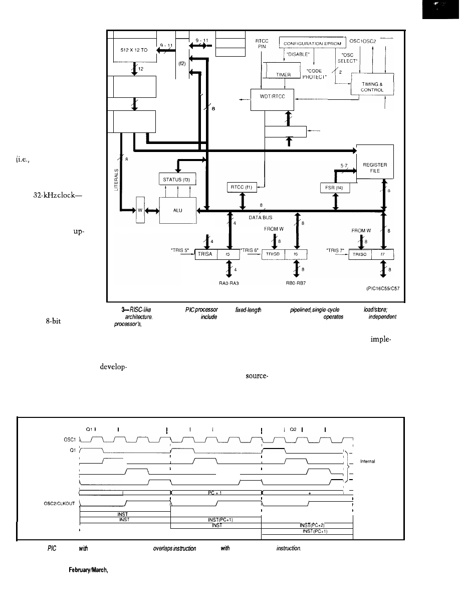
it operates off a clock
circuit separate from the
CPU. This aspect is
handy because the
watchdog remains
vigilant even if the CPU
clock is stopped. Stop-
ping the clock is some-
thing you might want to
do because the PIC is
“static” and includes a
sleep mode. These
features make very low
speed, voltage, and power
battery] operation
possible. For example, a
PIC consumes a miserly
3 volts at 32 microamps
with
wow!
CHEAP TOOLS
I tend to take
front tool cost for granted
because I have all kinds
of assemblers, simula-
tors, emulators, and
programmers gathering
dust. Thus, I haven’t
been in the market
recently, but I guess the
minimum tools setup for
a PAL or
micro runs
at least $1000, and I
EPROM
,
STACK 1
M C L R
PC
STACK 2
2048 X 1’2
WATCHDOG
OSCILLATOR/
INSTRUCTION
REGISTER
9
WDT TIME
CLKOUT
OUT
12
PRESCALER
“SLEEP
INSTRUCTION
6
DECODER
OPTION REG
“OPTION”
DIRECT ADDRESS
DIRECT RAM
ADDRESS
FROM W
5
G E N E R A L
PURPOSE
FROM W
RCO-RC7
ONLY)
Figure
features of We
include
instructions;
execution;
and
Harvard
Other useful features
a power-on-reset timer, a watchdog timer which
off a clock
of
the
and a sleep mode.
know it can get much higher.
prices (as low as $3) directly from
The Parallax setup basically
Cheap chips need cheap tools, and
Parallax.
ments a downloadable RAM version of
here Parallax Inc. fills the bill. They
I say “emulator” because it isn’t
the PIC with a few extras, like power
offer a complete PC-based
the classic emulator with expensive
supply, switch-selectable clock source,
ment package, including assembler,
features like real-time trace or
and so forth. These features allow
“emulator,” and device programmer
level debug. Rather, it more closely
quick code change/debug iterations
for only $449. You can also buy small
corresponds to an EPROM emulator
without the cost and time to burn an
quantities of the PIC at very decent
you might use with a regular micro.
actual EPROM version of the chip.
a 2
a 3
a 4
PC
(Program Counter)
(RC Mode)
I
a2 a3 I 04 a1 a2 03 I a4 01
a3 a4
Phase
Clocks
PC
PC 2
Fetch
(PC)
Execute
(PC-l)
Fetch
Execute
(PC)
Fetch
Execute
Figure 4-The
operates
a four-c/o&period cycle and
execution
the fetch of he next
102
Issue X25
1992
The Computer Applications Journal
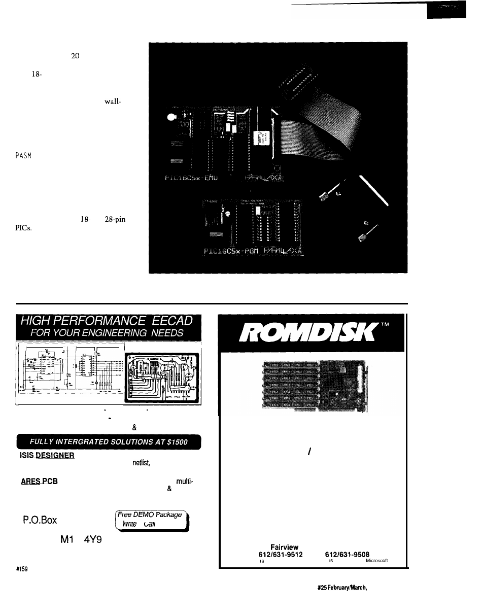
The emulator/programmer setup
(combined: a tidy
sq. in.) connects
to the PC printer port on one side and
to an
or 2%pin DIP header on the
other using a 6” ribbon cable, which
plugs into the target PIC socket. Each
board is powered by a small
mount transformer, so they can be
used together or separately.
Entering a program on the PC
using your favorite editor, and then
assembling that program using
. EXE
completes the developmen-
tal procedure. Next, you can use
PEP. EXE
to download the object code
to the emulator, run the program, and
after everything is working, burn a PIC
using the device programmer. The
latter includes LIF (low insertion force)
sockets for both the
and
A key point is the Parallax
PASM
redefines the instruction syntax, so it
differs from the “official” definition by
Microchip. Normally, such a move
would be considered taboo, but I’m
letting it pass for two reasons. First, I
don’t have to worry about maintaining
ARES PCB
I
ISIS DESIGNER
Easy to Use PC Software ICON Based Mouse Driven
Ultra Fast Performance Advanced Editing Tools
Output to Printers, Plotters Lasers
i s t h e S c h e m a t i c C a p t u r e f o r a n y o n e
needing to enter designs. Provides
multi-sheet,
user configurable partslist & Electrical Rules Check report.
A new autorouter uses an advanced
strategy to achieve very high connection rates it’s fast!
10 copper layers, Design Rule Checker and MORE.
R4 SYSTEMS Inc.
451
West Hill, Ontario
Canada
E
or
Today
(416) 439-9302
Download DEMO from BBS at 416 289-4554 (2400/8/N/l)
High Performance
Multimegabyte Disk Emulators
NEW MODELS LOWER PRICES
l
Floppy Drive and multimegabyte
emulators for ISA bus computers
l
180K to 14 MB capacities
l
EPROM, Flash or SRAM technologies
l
Autobooting, Single or Dual disk
emulation under PC or MS DOS
l
List prices from $195
CURTIS, INC.
2837 No.
Ave.
l
St. Paul, MN 55113
FAX
PC DOS a trademark of IBM; MS DOS a trademark of
60
The Computer Applications Journal
Issue
1992
103
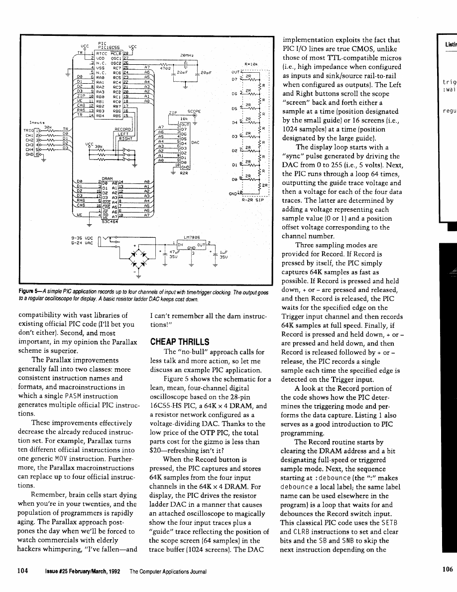
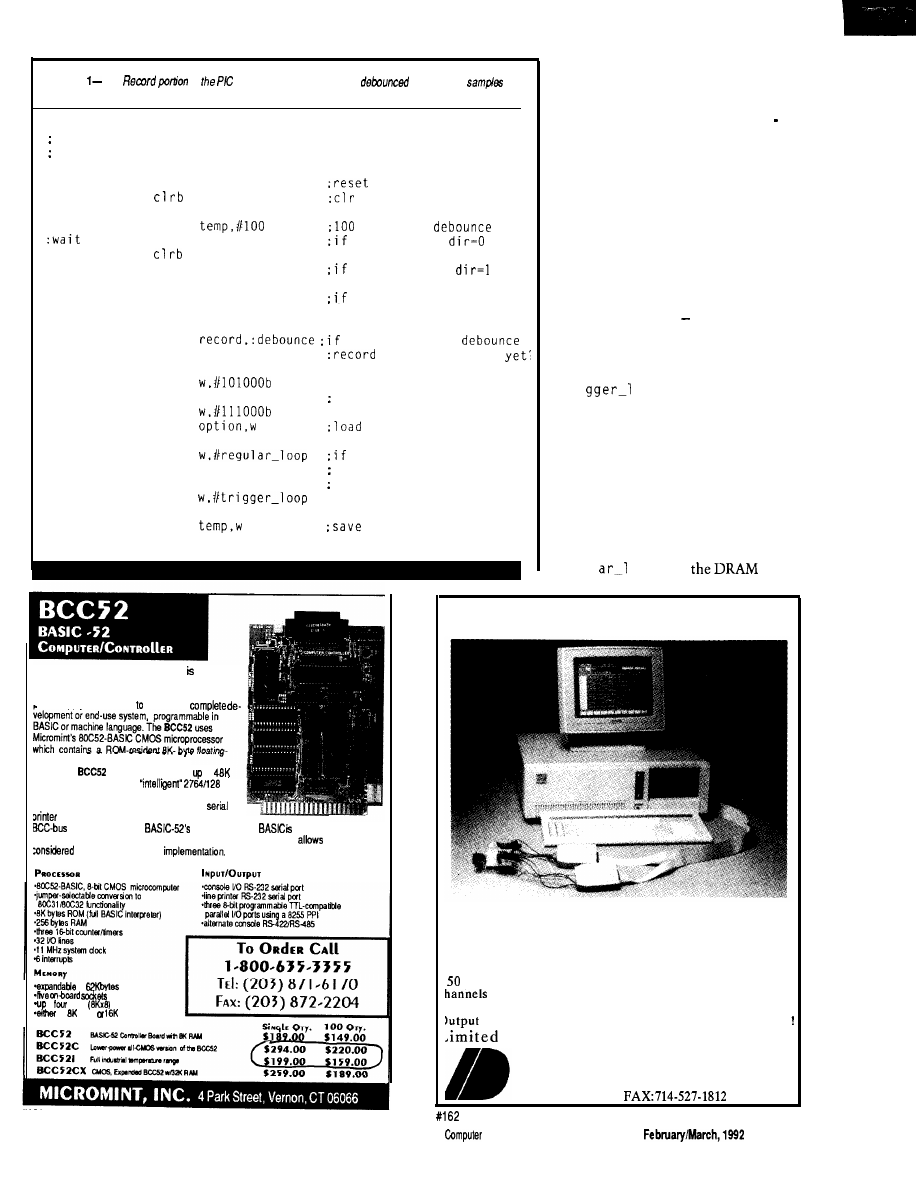
Listing
The
of
code shows how buttons are
and how the
are taken and stored.
Record pressed get final record command and read 64K
samples into DRAM
handle-record call
clear-address
address
bit
bit to flag left/right
:debounce
mov
cycles of
sb
left
left button,
direction
sb
right
right button,
setb
direction
snb
left
either button, set bit
sb
right
setb bit
jnb
record, reload
djnz
temp.:wait
not pressed, 100
mov
:get + or edge for option
snb
direction
according to direction
mov
mov
option with w
mov
left or right button is
snb
left
still pressed, then do
sb
right
per-sample triggering
mov
write-entry
mov
loop address in temp
(continued)
The BCC52 Computer/Controller Micromint’s
hottest selling stand-alone single-board microcom-
puter. Its cost-effective architecture needs only a
power supply and terminal become a
point BASIC-52 interpreter.
The
contains sockets for to
bytes of RAM/EPROM, an
EPROM programmer, three parallel ports, a serial
terminal port with auto baud rate selection, a
port and is bus-compatible with the full line of
expansion boards.
full floating-point
fast and efficient
snough for the most complicated tasks, while its cost-effective design
it to be
for many new areas of
and end-use applications.
It can be used both for development
to
b
6264
stab RAM
an 2764
27126 EPROM
61
state
of a bit. It looks a little strange,
but you can step through it yourself to
see how it sets and clears b i t [trigger
mode/full-speed mode) and d i r ec
t i on (rising or falling edge if trigger
mode).
The PIC opt i on register is
written to configure the RTCC trigger
input as rising or falling edge. Note
again how the skip instruction makes
the common chore of loading a register
with a bit-dependent value easy.
Similar code sets up a looping address
(which
is
saved in
temp)
depending on
the state of the + or keys
(regular_looportrigger_loop).
In trigger mode, the PIC spins on
the three instructions at
tri
oop
waiting for the LSB of
the RTCC to change from 0 to 1 (i.e.,
when the RTCC increments in
response to the appropriate edge on the
trigger input). Meanwhile, the second
instruction checks whether the Record
key is pressed providing a way to
cancel sampling should the trigger
input fail to make an appearance.
The core data capture routine at
regul
oop
does
PC-Based Logic Analyzers
Special Anniversary Sale !!
ID160 for $495 (regular $695)
ID161 for $595 (regular $895)
ID320
for $995 (regular $1595)
MHz or 100 MHz
Sampling
l
8K
Trace Buffer
l
16 or 32
*Multi-Level Triggering
*State Pass Counting
Event Timer/Counter *Performance Histograms *Hardcopy
*Disassembles popular 8-bit micros *and much more
Time Offer. Money Back Guarantee
I N N O T E C D E S I G N , I N C .
6910 Oslo Circle, Suite 207
Buena Park, CA 90621
Tel: 714-522-1469
The
Applications
Journal
Issue125
105
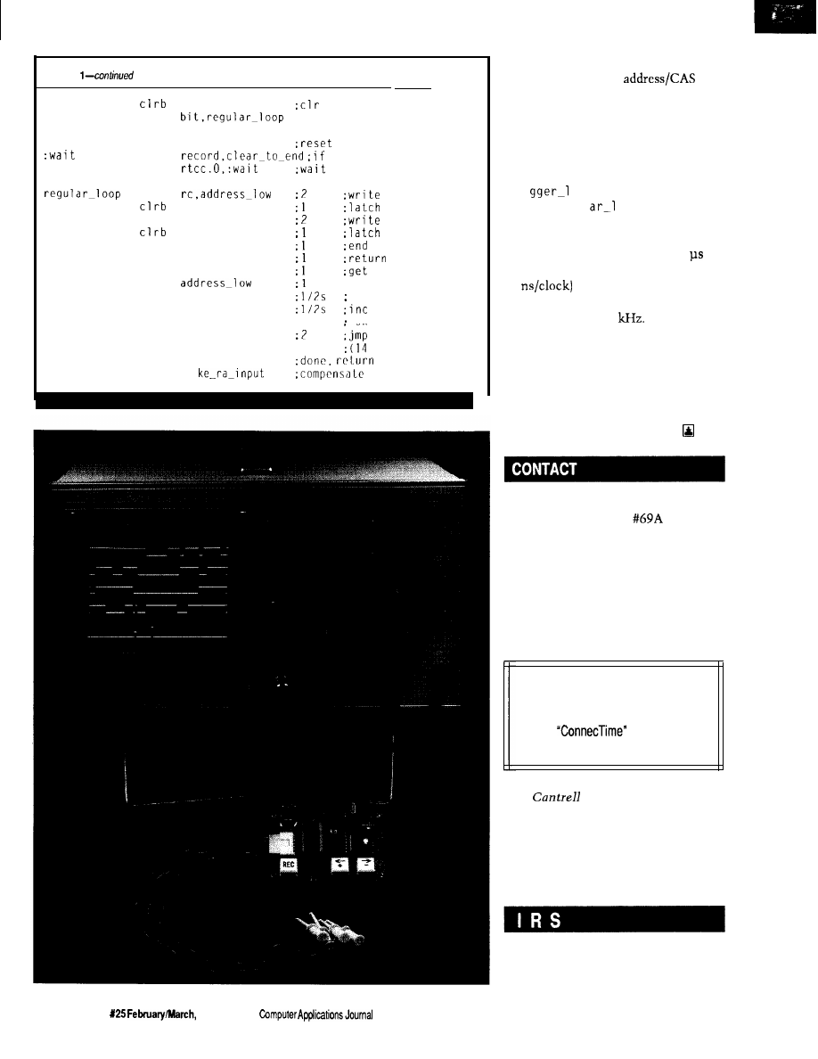
Listing
we
we to enable dram write
jnb
:if no button, regular
trigger-loop
clr
jnb
jnb
mov
mov
setb
setb
mov
inc
snz
incsz
rtcc
rtcc
record button, abort
for trigger edge
ras
rc.address_high
cas
cas
ras
w.temp
address-high
W
setb
we
jmp
ma
c y c
row address
into dram
column addr
in dram, write
write cycle
ras high, too
loop addr in w
:inc low address
skip if not 0
hi addr
skip if 0
to loop
cycles/loop)
we high
for write-entry
boogie by asserting the row address/
RAS and the column
at
which point whatever data is sitting
on the four DRAM inputs is stored.
The last steps increment the address
and exit the loop when 64K samples
are captured. Note how the final jump
instruction loops back to either
tri
oop
(for sample-per-trigger
mode) or
regul
oop,
depending
on the address in
W
(which is saved/
restored from variable t
emp).
The core loop takes only 2.8 to
execute (14 cycles x 4 clocks/cycle x
50
thanks to the fact the PIC
is running at 20 MHz; thus, it acquires
the data at over 350
Not bad at
all. In fact, it acquires data much faster
than any number of more expensive
micros that shall remain nameless
[lucky for them).
Oh well, the overpriced competi-
tors have one big advantage over the
PIC-at least they aren’t cheap.
Parallax, Inc.
6200 Desimone Lane
Citrus Heights, CA 95621
(916) 721-8217
Microchip Technology, Inc.
2355 West Chandler Blvd.
Chandler, AZ 85224-6199
(602) 963-7373
Software forthisarticle isavailable from
the Circuit Cellar BBS and on Software
On Disk for this issue. Please see the
end of
in this issue for
downloading and ordering information.
Tom
holds a B.S. and an
M.B.A. from UCLA. He owns and
operates Microfuture Inc., and has
been in Silicon Valley for ten years
working on chip, board, and system
design and marketing.
425 Very Useful
426 Moderately Useful
427 Not Useful
1 0 6
Issue
1992
The
CEBus
Goes
Coax
Also Visit
the Home of
the Future
Ken Davidson
nyone looking
r my regular
us update in the
form of a full-length
feature article
The CEBus specification is being
is going to be
this time around. It’s really
developed and released in stages. It has
nothing to be disappointed about,
though. There just isn’t as much news
been broken up into sections including
to tell you about as there’s been in the
past. That doesn’t mean no work is
CAL and the upper network layers,
being done on the CEBus standard; it
simply means most of the work is
each of the physical media, and a num-
done. Now the waiting begins.
ber of key pieces such as routers,
brouters, and Node 0. [If anything I
mention here is at all unclear, I refer
you to my previous CEBus articles
found in issues
and
of
Circuit Cellar INK for more details.)
Once the CEBus core committee
has hammered out its best effort on
any given piece, it is sent out to the
entire membership (and anyone who
requests and is willing to pay a copy)
for comment. At the end of the com-
ment period, which usually lasts a few
months, all suggestions and negative
comments are collected and responses
are prepared by the committee. All
negative comments must be addressed,
even if it is to reject them. Any
changes the core committee deems
worthwhile are submitted to the mem-
bership for comment again to make
sure nobody has a problem with what
was supposedly fixed.
When everybody is happy with the
proposed standard, the committee
submits it to EIA as an interim stan-
dard. This standard is the first time the
specifications are fixed enough for
someone to design a product. It will
remain in place for several years while
people produce new designs. Assuming
no major problems are discovered with
it during that period, the specification
finally becomes a real standard.
Right now, most portions of the
are somewhere between the ini-
tial comment phase and acceptance as
interim standards. Some have already
been dubbed interim standards, while
others are having last-minute details
worked out before being released for
initial comment. Table 1 gives a brief
summary of where each of the major
portions was as of this past December.
COAX COMES ALONG
One specification that is new
CXBus is complicated. With the
limited space I have back here, I’m
going to necessarily simplify the de-
tails. My intention is to give you a
flavor for how CXBus functions, per-
haps only enough to allow you to envi-
sion how your house might be wired
and how devices interact with each
other. For complete specifications, I
refer you to EIA where you may obtain
since my last article is coax
As you can see from the table, the
a copy of the proposed
comment period for CXBus ended
December 31, so the committee
should be up to its ears in comments
as you read this.
CXBus uses a series of RG-6 coax
cable pair branches that originate at
Node 0. Each branch goes to a different
area of the house and terminates in a
four-way splitter. Each of the splitter
outputs goes to a pair of jacks within
the area serviced by the branch. Pre-
sumably, one branch would go to, say,
the area composed of living room,
dining room, and kitchen while an-
other branch would go to, say, the
bedrooms. Total cable length between
Node 0 and any final tap may not ex-
ceed 150 feet.
One of the cables in each pair
handles external video while the other
handles internal video. External video
is anything that originates outside the
house such as CATV or an antenna.
Internal video is anything generated
108
Issue February/March,
1992
The Computer Applications Journal
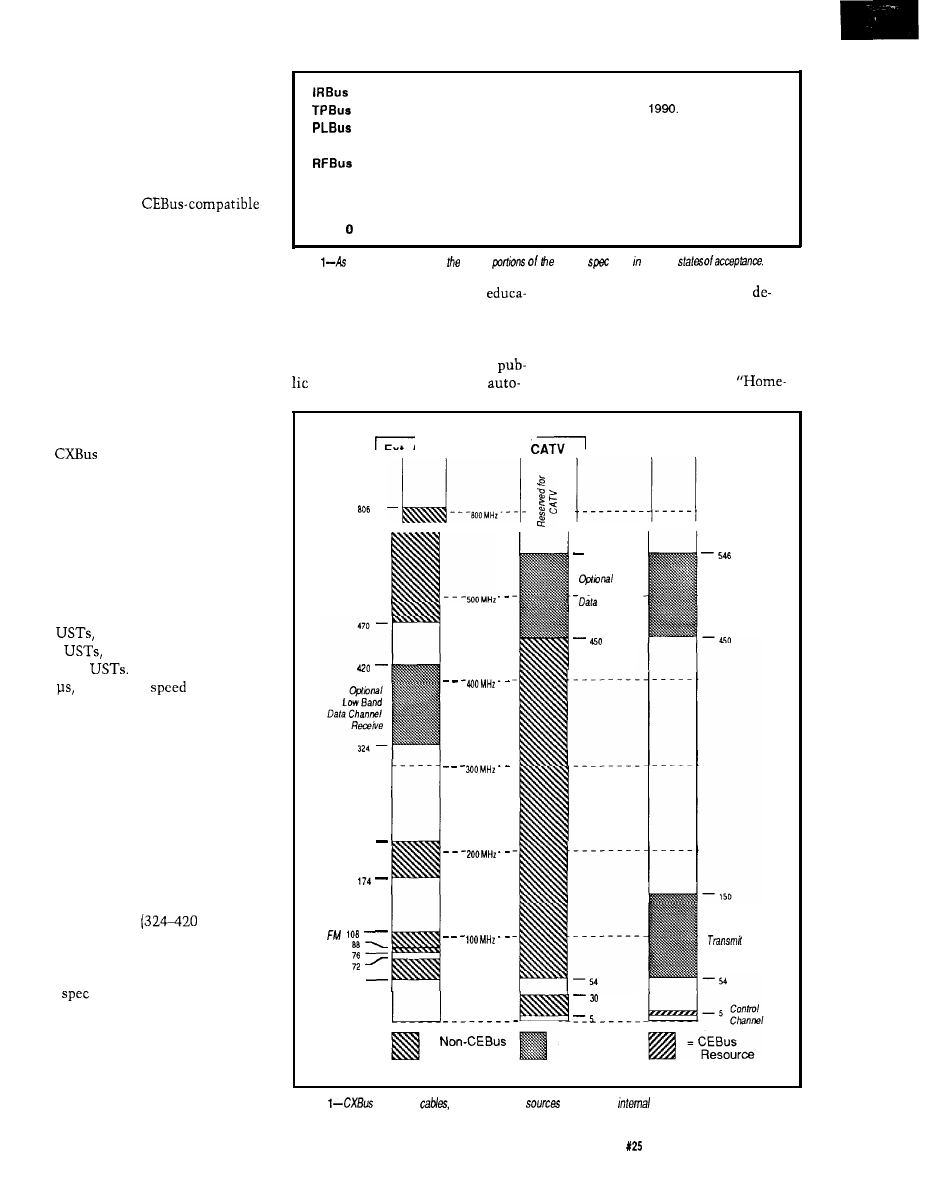
in-house such as VCR output, cam-
eras, or computer displays. The inter-
nal cable also carries the CEBus con-
trol channel.
Older devices that aren’t CEBus
compatible need only attach to the
external cable to receive signals like
they always have.
devices must attach to the internal
cable to reach the control channel, and
may also connect to the external cable
for access to outside sources.
Figure 1 shows the frequency
assignment on each of the cables.
The CEBus control channel spans
4-6 MHz on the internal cable. The
signal is an amplitude-modulated RF
carrier. CEBus devices transmit con-
trol signals on 4.5 MHz and receive
signals that are retransmitted by Node
0 on 5.5 MHz.
uses the same superior/
inferior signaling scheme for the con-
trol channel as the other media. The
presence of the carrier denotes a supe-
rior state while the absence denotes an
inferior state. The four CEBus symbols
are represented by one of the two
states being asserted for multiples of
the Unit Symbol Time (UST). A “one”
bit lasts one UST, a “zero” bit lasts
two
an “end-of-frame” lasts
three
and an “end-of-packet”
lasts four
A single UST lasts
100
giving a top
of 10,000
“one” bits per second.
The frequency band from 54 MHz
to 150 MHz on the internal cable is
reserved for CEBus devices to transmit
data. Within that space, 64 channels,
each 1.5MHz wide, are defined. When
a device needs more bandwidth, adja-
cent channels may be requested in
groups of 2, 4, 8, 16, or 32 and are com-
bined into a single block. The data is
received by Node 0 and is
retransmitted on either a low band on
the external cable
MHz) or a
high band on either the external or the
internal cable (450-546 MHz).
That covers the basics. The com-
plete
is about forty pages long, so
I certainly can’t do it justice in only a
few paragraphs.
IN THE PUBLIC EYE
If you’ve read my article in this
issue about the Bright Home, you
Approved as part of interim standard in October, 1990.
Approved as part of interim standard in December,
Comments have been addressed. Several issues still need to be resolved.
CXBus
Initial comment period ended December 31, 1991.
Several system alternatives are being reviewed by the committee. Final
selection should be made by the time you read this.
CAL
Comments to changes are being addressed by the committee.
Router
Approved as part of interim standard.
Node
To have been released for comment in December, 1991.
Table
of
December,
1991,
major
CEBus
were various
already know that I feel public
mate a home with off-the-shelf
tion is a big part of what will make or
vices.
break home automation’s acceptance
Most anyone who watches PBS
by the masses. I recently came across
knows about “This Old House.” A
another example of exposing the
similar show that started appearing on
to what can be done now to
PBS a few years ago is called
EXTERNAL CABLE
Ext. Antenna OR
INTERNAL
CABLE
UHF
216
VHF
r
VHF
L
54
546
High Band
Channel
Receive
CAN
Cab/e
High Band
Data Channel
Receive
Data Channel
=
Resource
CAN Return
= CEBus
Resource
(reserved)
Figure
uses hvo
one for external
and one for
sources
The Computer Applications Journal
Issue
February/March, 1992
109
time.” This show is hosted by a cheery
man and woman duo who make every-
thing look like it can be done on your
first try in a matter of minutes, even if
it’s erecting a two-story log cabin. The
projects tackled by “Hometime” don’t
always center around renovating older
houses. They often do all new con-
struction, and sometimes they try to
explore the unconventional. For ex-
ample, they really did build the log
cabin I mentioned above.
“Hometime’s” latest project is the
home of the future. More specifically,
what a house might be like 20 or 30
years from now. The entire project is
fascinating, even though the home
automation
is only a small part
of overall scheme. They cover every-
thing from the
to the
structure to the appliances to the land-
scaping.
The home automation scheme
was designed by Mike
who
was instrumental in putting together
the “The Installer’s Guide to
Home Automation” I discussed in the
last issue, and
Parks, who wrote
the introduction to this issue’s Build-
ing Automation feature section. The
system they used is produced by AMX
(Dallas, TX) and was originally de-
signed to automate the boardrooms of
large companies. AMX has been seeing
a growing application of their system
in high-end homes as a complete auto-
mation solution.
The home of the future is located
in Minnesota and was part of a local
“gallery of homes” tour where thou-
sands of people toured the home dur-
ing a several-day period.
The series aired in five half-hour
segments starting last November,
resulting in thousands more people
being exposed to the ideas behind
home automation. You might be lucky
enough to find it locally in reruns, or
you can buy a complete video from
“Hometime” that contains all five
segments plus additional material. At
$9.99 plus $2.50
it can’t be beat.
Also keep an eye out for the April ‘92
issue of Better Homes and Gardens
where there will be an extensive write-
up about the home.
q
Thanks to Tom Mock and George
Hanover at EIA for their continued
information flow, to Azt
AMX for first alerting me to the
Home of the Future series, and to
Mike
for his very helpful
minute details.
Electronic Industries Association
200 1 Pennsylvania Ave. N.W.
Washington, DC 20006
(202) 457-4975
(Video)
Home of the Future
150 N. 6th St.
Philadelphia, PA 19 106
(800) 736-3033
(Comments about the home)
Home of the Future
4275
Dr.
Chaska, MN 553 18
428 Very Useful
429 Moderately Useful
430 Not Useful
The Ciarcia
Design Work
Does your big-company marketing
department come up with more ideas than
the engineering department can cope with?
Are you a small company that can’t
afford a full-time engineering staff
for once-in-a-while designs?
Steve Ciarcia and the Ciarcia Design
Works staff may have the solution for you.
We have a team of accomplished programmers
and engineers ready to design products or solve
tricky engineering problems. Need an infrared
remote controller, multi-channel data logger,
or
drill controller? The team has the talent
to design and manufacture it!
Whether you need an on-line solution for a unique
problem, a
for a startup venture, or just plain
experienced consulting, the Ciarcia Design Works
stands ready to work with you. Just send me a fax
discussing your problem and we’ll be in touch.
Ciarcia design works!
Call
. Fax
872-2204
THE HOME AUTOMATION ERA
WHY
WAIT?
JOIN THE
HOME AUTOMATION
Pioneer the development of this new growth industry
along with industry leaders.
Why watch the market
when you can shape it?
Participate in trade conventions, exhibits, workshops,
and seminars. The Association will provide informa-
tion on trends, forecasts, and market activities to
support more intelligent marketing decisions.
The Association also plans to promote
home automa-
tion
in the widest sense, monitoring the current state
of the art as well as the social, economic, legal, and
other effects of home automation on every level of
society.
For futher informationonmembership, pleasecontact
Nicholas Pyle at:
Home Automation Association
1223 Potomac
Street, NW
Washington, DC
333-8579
110
Issue
February/March, 1992
The Computer Applications Journal

The Circuit Cellar BBS
bps, 24 hours/7 days a week
(203)
incoming lines
Vernon, Connecticut
Not
the magazine been given a new look, but
the
installation of the new TBBS 2.2, the look of the Circuit Cellar BBS
will also start to change and evolve. Nothing
a
needed
facelift. I’m hoping the changes will make the BBS easier to
use for all callers.
Also like the magazine, while the look may be somewhat
different, the content and quality of
messages posted by our
users will remain as good as ever.
In this issue, we ‘re going to look primarily at stepper motors,
with brief forays into using the IBM PC printer port bidirectional/y and
bow the magnetic stripes on bank and credit cards are formatted.
the magnetic stripes.
From: MATTHEW TAYLOR To: ALL USERS
I am wondering how info is stored on a magnetic stripe.
I can fathom reading from and writing to a card if 1) a track
is used that contains clock info or 2) a motor is used to drag
the card across a head at a predetermined speed.
Do most cards use an encoding scheme that allows
clocking info to be recovered, multiple tracks, a combina-
tion, or what?
Any help or info on companies dealing in this would be
appreciated.
By the way, what sort of data densities are safe to lay
down (i.e., can be recorded onto a stripe and withstand a
year or so in a wallet)?
From: DAVID LAWSON To: MATTHEW TAYLOR
Credit cards have three tracks that can be used for data
storage. Track one is recorded at 210 bits per inch with up
to 79 characters. It is usually used by the airline industry
and carries an account number (up to 19 characters), 2 to 26
characters for a person’s name, with the balance of charac-
ters for discretionary data.
Track two is used by the American Banking Associa-
tion and has your credit card information on it. It is written
at 75 bits per inch with a maximum of 40 characters. It
carries up to 19 digits of account number, expiration date
(MMYY), with the remainder any data desired by the card
issuer.
Track 3 is used by automatic teller machines. This
track is written at 210 bits per inch and has up to 59
characters. Data on track 3 is primary account number,
expiration dates, validity dates, service restrictions, and
other data the ATM might use.
All tracks are written with phase-coherent FM record-
ing and are synchronous for self-clocking data recovery.
There are other flags embedded in the stripe’s data like start
sentinels, frame separators, end sentinels, and so forth. The
actual characters use 5 bits and odd parity (if I remember
the parity right).
Reading is fairly easy if you have one of the
designed for reading cards. Writing is quite another issue.
The problem is getting the data written at a constant
density. I have a writer that uses an optomechanical
encoder to signal the on-board processor when to write the
data.
From: MATTHEW TAYLOR To: DAVID LAWSON
Thanks for the wealth of info. I’ve been currently
playing with a single-track card reader I’ve built. I also have
an optical rotary encoder installed.
A very common question we get on the BBS is how to make an IBM
PC printer port bidirectional. A hardware modification has been
presented in the past, but it’s often preferable to use an unmodified
port, as is described here.
From: JOHN APPLEYARD To: ALL USERS
I’d like to utilize the parallel port on an IBM PC for
bidirectional operation. Can anyone tell me the port
numbers so I can access the port from BASIC (using INP
and OUT). How about
for the port? Thanks.
From: ED
To: JOHN APPLEYARD
Take a quick scan through the message base, as this
topic comes up quite often. The DDT-51 project used a
bidirectional parallel port and the code is available for
downloading.. admittedly in Pascal, but it’s there.
The Computer Applications Journal
February/March, 1992
111

There might be other files available that touch on this:
5 32
12
have any of you regulars put together the definitive parallel
6 64
10
port summary file yet?
7 128 11
From: JAKE MENDELSSOHN To: JOHN APPLEYARD
Problem #l-Finding the parallel port:
10 DEF SEG
20 PTR =
+
PTR is the output address as in:
30 OUT PTR.128
is the input address as in:
40 X =
Special Note: pins 15, 13, 12, and 10 are all
noninverted, so their corresponding bits are set when the
pins are high. Pin 11, however, is inverted, so its bit is
cleared with the pin is high.
4. When you read the input byte with
NP
you will get a number you can decode to determine which
input pin is high and which is low. There are only five
inputs and thus the first three bits are not connected to any
pins. Be careful, on some computers these three bits are
forced low and on others they are forced high.
Problem
are the output pins?
Pin:
2 3 4 5 6 7 8 9 1 8
Data Bit:
0 1 2 3 4 5 6 7 Gnd
These outputs are standard DB-25 parallel ports.
From: BOB PADDOCK To: ED
See if you can dig up “Interface Circuit for Printer Port”
LAB- 13950, from
NASA Tech Brief:
Purpose:
Problem
are the input pins?
Pin
Name
10
ACK
11
Busy
12
Out of Paper
13
Select
15
Printer Error
“This invention is an electronic circuit, which when
used with appropriate software, converts the printer port on
an IBM PC, XT, AT or compatible personal computer (PC)
to a general-purpose
data, 16-bit address bus that is
cable of interfacing to a multitude of devices.”
Summary:
There can be a lot of problems in using these inputs
with different computers. These inputs are VERY nonstand-
ard and there are a lot of variations from machine to
machine.
For example:
1. Not all computers have all of these inputs connected
to the DB-25 (e.g., pin 12: Out of Paper)
2. On some computers these pins float high and on
other computers they float low. Don’t assume they are one
way or the other. Force them where you want with pull-up
or pull-down resistors.
“The purpose of the printer port interface (PPI) is to
convert any existing printer port on the IBM PC or compat-
ible to a general-purpose bus. Since the printer port on the
IBM PC was designed for the specialized task of outputting
data to a printer, the PPI must be able to hold an address as
well as provide for data flow in both directions.
In order to output to the external device, the PC printer
port sends the address, data, and control values to the PPI
one byte at a time. As the PPI receives this information, the
PPI latches it on the proper output lines. Once the address
and data are latched, the external device is signaled to
accept the values.
3. Here is how to read the bits of the input byte:
Bit Value Pin
0 1
Not Connected
1 2
Not Connected
2 4
Not Connected
3 8
15
4 16
13
In order for the PC to read from the external device, it
first sends the address and control to the PPI. The external
device then responds with eight bits of data on the input
lines. Since the printer port has only five inputs, the PPI
transfers the eight bits of data to the PC four bits at a time.”
It uses several
latches and buffers. Request
13950 from:
NASA STI Facility
Manager,
Division
P.O. Box 8757
Baltimore, MD 21240-0757
112
Issue
February/March, 1992
The
Computer

Stepper motors are often used when precise speed and position
control are necessary. To get maximum performance from them
takes some tricks, though.
From:
JAY ALEXANDER ABEL To: ALL USERS
I am working on a stepper motor project, and I seem to
be running out of torque. It appears I may be able to eke out
what I need by driving the motor with sine waves in
quadrature, but I lack a simple circuit for doing this. The
same circuit is *usually* used for microstepping applica-
tions. If anyone has any experience with the above, or has a
simple, elegant solution, please share it.
From: PELLERVO KASKINEN To: JAY ALEXANDER ABEL
The amount of torque you can develop is dependent on
your motor and only in the second phase of evaluation on
the driver circuits, because those circuits are considered
selectable or adaptable.
As far as the motors go, you have several issues to
consider. For the first, the frame size. For the next, number
A NOTICE TO OUR READERS:
The Computer Applications Journal will
occasionally provide a listing of subscribers
to vendors with offers of substantial interest
to our readers. If you would prefer not to
be part of this listing, send a mailing label
from the outside cover of The Computer
Applications Journal along with your
request to:
BOX 3050
19398
114
1992
The Computer Applications Journal
of poles and number of steps per shaft revolution. And for
the third, the magnet material.
The number of poles is usually four, but there is a
pole design by Vexta. Anyway, the torque also is not the
same in standstill as it is at a high speed. And then there are
three resonances, where you tend to almost totally miss any
torque at all, in most motors. The
motors cure two of
the three resonances, if I remember correctly.
For any single motor, the torque is proportional to the
winding current you apply, within two constraints: over-
heating and demagnetizing/nonlinear saturation. Normally
only the overheating is a real design problem. But for most
people, the problem seems to be lack of torque at the higher
speeds, or inability to jump from standstill into those
higher speeds or even reversal of rotation direction. The
acceleration is normally taken care of by ramping the pulse
frequency up gradually. You probably know of that already,
so I’ll move on.
The real high-speed torque is limited by the inability of
any practical circuit to provide instantaneous stop of
current in one winding and at the same time an instanta-
neous jump of current from zero to full nominal value in
another winding. This is due to the winding inductances
and also due to a transformer effect inside the stepper
motor. What you can do depends on what you already have
done. The sine wave drive as used for microstepping is great
at minimizing the inductive effects and the transformer
effects as well, if it is properly tuned for the particular
motor you are using. But at the same time, it seldom
provides for an ability to force a fast change of current for
the commutation.
In full or half stepping, you would use two power
supplies and current sensing. You feed the winding from the
high-voltage supply after each commutation, until the
nominal winding current has been achieved and then
switch to the lower-voltage.supply for the rest of the step
time. The voltage available from the initial high supply
determines the maximum speed/torque you can achieve,
but does not help if you are limited in the torque at low
speeds as well. In such a case, my suggestion would be to
get a beefier motor. Or provide artificial cooling to the poor
small motor and then increase the supply voltage by
whatever amount the added cooling warrants.
From: JAY ALEXANDER ABEL To: PELLERVO KASKINEN
Your insights were very useful to me, and in fact your
recommendations parallel my own empirical conclusions.
Actually, my original message was poorly worded, which I
think obscured my question. I’ll attempt to clarify.
I am building a magnetic reading device which steps
the medium and samples the output from the head, so I not
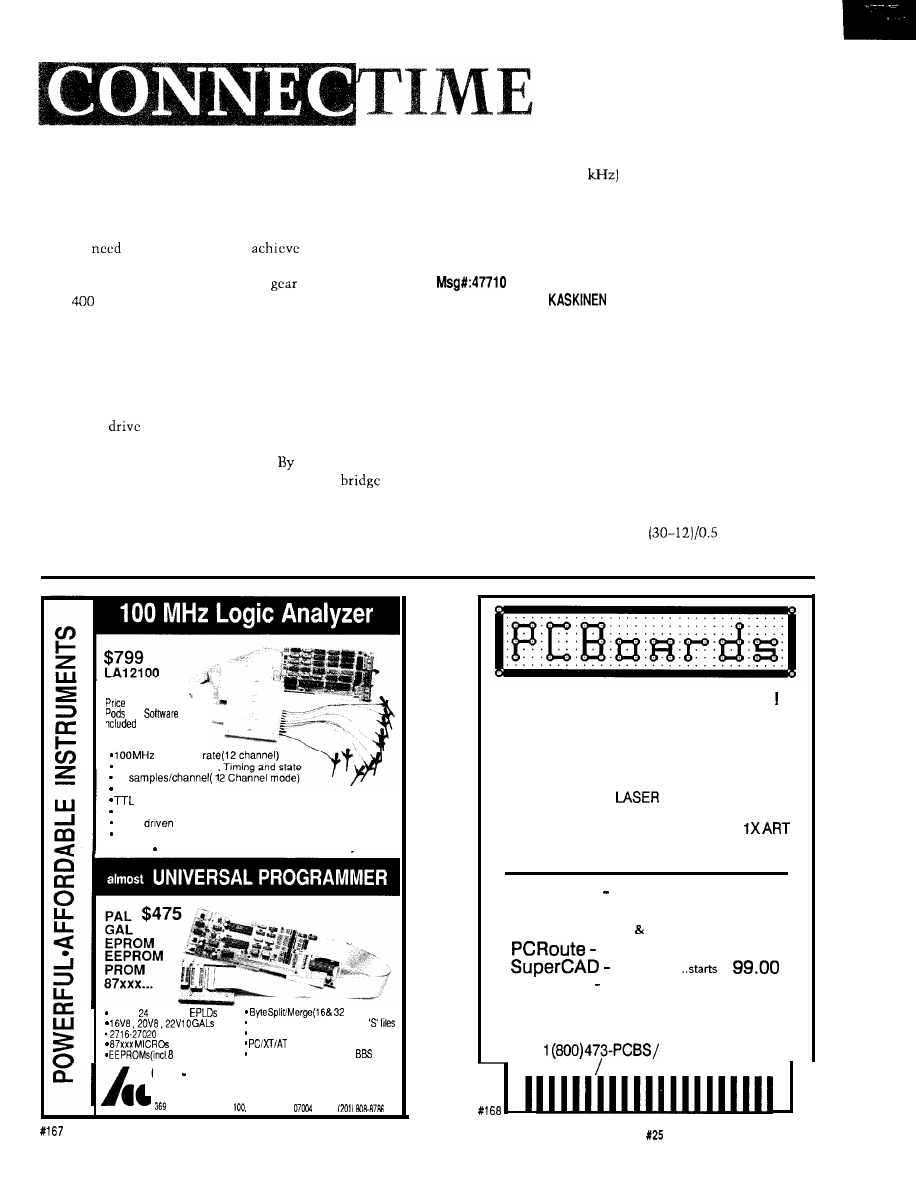
only need resolution, but speed as well. I chose not to use a
DC motor and encoder because the physical size and high
cost were problematic. The stepper motor in question is
very inexpensive. Howcvcr, I discovered for my application,
I would
to step at 800 pps to
my other design
goals, clearly at the limit of stepper technology.
My solution was to increase the
ratio so a rate of
only
pps is required, and to make multiple samples per
step. Hut for this to work I need to ensure there is minimal
cogging. There are two basic methods to accomplish this:
increase inertia or
USC
sinusoidal drive signals. The former
would lengthen the acceleration time, which as Murphy’s
Law predicts, is also unacceptable.
I then searched for a simple method of generating
sinusoidal
waveforms. I found no simple, elegant,
hardware method. I did, however, find another method
which I would like to share with you. using a higher
drive voltage, I am using the enable pins on the
driver to pulse-width modulate the drive to the two coils.
For each step, I take ten or so samples of input, and during
each step I enable the two motor phases for longer or
shorter periods, and, in effect, I get sinusoidal drive currents
since the drive signal (4
is well beyond the mechanical
and electrical self-resonant point of which you spoke. As I
already had the sampling interrupt service routine, the cost
in software is minimal, and the hardware cost is of course
nil. Thank you for your timely comments.
From: PELLERVO
To: JAY ALEXANDER ABEL
Looks like you have the most elegant way already, with
the PWM at the enable pin. However, just a couple of points
to amplify: There is always some kickback when you
switch current into and out of a coil. Even more so in a
motor, where you have the transformer action as well. The
normal first thing people attempt is to put a direct free-
wheeling diode over the coils. But that slows down the
current change quite badly. What should be done is to have
transistors that tolerate a high voltage and then have a
suitable series resistor with each of the freewheeling diodes.
If your coil current is 0.5 A at 12 V and your transistors can
handle 60 V safely, you could allow the kicks to reach as
high as 30 to 40 V by putting in a
ohm resistor
(36 ohms).
is complete
and
sampling
24 Channels(50 MHz).
2K
24 Bit trigger word
threshold level
Internal and External Clocks
Menu
software
FREE software updates on BBS
More sophisticated units also available
20 and pin PAL
S
,
bit)
JEDEC, INTEL HEX, Motorola
EPROMs
Dallas NVS RAM programming
COMPATIBLE
pin serial)
FREE software updates on
Call (201) 808-8990
Link Computer Graphics, Inc.
Passaic Rd.. Suite Fairfield.
NJ
FAX:
P-C-B ARTWORK MADE EASY
Create and Revise PCB Art in a Flash
* For IBM’s & COMPATIBLES
* HERC, CGA, EGA, VGA, SUPER-VGA
*AUTO GROUND PLANES
* DOT- MATRIX,
and PLOTTER ART
* GERBER and EXCELLON OUTPUT
* CREATE YOUR OWN FILMS with
* LIBRARIES * HELPSCREENS *MENUS
* DOWNLOAD DEMOS from 24 hr. BBS!
PCBoards
layout program
99.00
PCBoards HP or HI PEN PLOTTER DRIVER 49.00
PCBoards GERBER MCELLON Disk 49.00
autorouter
99.00
schematic .
at
Demo Pkg.
(demos of all 3 programs)
10.00
Call or write for more information
PCBoards
2110 14th Ave. South, Birmingham, AL 35205
(205)933-l 122
BBS FAX (205) 933-2954
The Computer Applications Journal
Issue
February/March, 1992
115
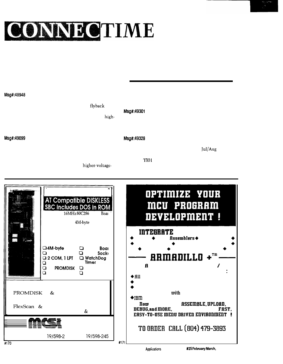
Another thing I want to mention is any card readers I
know of use a DC motor. When people can make model
airplanes containing such motors, I can hardly see it as a
size issue. But that is just a shot in the dark, if you prefer
the steppers, you do. I have, despite my experience with
them, retained a preference of DC motors.
From: BRUCE GRAHAM To: PELLERVO KASKINEN
In a two-voltage scheme you can use the
voltage for shutting down a coil to charge a capacitor which
sits on top of the high-voltage supply. This helps the
speed performance by keeping the high-voltage supply from
dropping at high speed.
From: PELLERVO KASKINEN To: BRUCE GRAHAM
Naturally, you are bound to try to use energy-minimiz-
ing techniques in the commutation. Trying to preserve the
stored energy in a capacitor is an age-old way, with age-old
side effects. One is that you have to have
rated transistors. Not a real problem today, but gave plenty
of headaches to the early brave experimenters. Another one
is that the voltage level is strongly affected by the frequency
of commutation. So, watch out!
Stepper motors are sometimes “microstepped” to get more resolution
from them. Just bow is such a feat accomplished?
From: MARC WARREN To: ED NISLEV
How
does one microstep a stepper motor? Are there
any old postings in the file area? Thanks!
From: ED NISLEV To: MARC WARREN
Well, the quick overview was in the
‘88 issue
of
Circuit Cellar INK
disguised as a sonar scanner using the
venerable
ultrasonic range finder.
Basically, if you’re using digital drivers you’re limited
to “half-stepping” which means you turn on both drive
IND-286 SBC
Complete
Single
Computer for embedded PC appl
cations features a
PROMDIS
disk emulator with battery back-up ax
an MS-DOS 3.3 compatible disk ope
ating system in ROM.
Features Include:
DRAM Xl Size
Keyboard Port 80287
IDE Disk Port
4M
Floppy Port
100% PC/AT
Optional Vidc
Compatible
Daughter Bd.
Other Products:
l
IND-88 PC/XT Single Board Computers
l
III IV Disk Emulators
l
EPROM/RAM Memory Board
l
FLASHDISK Driver for Micro Soft FFS
l
I II Bar Code Decoders
l
Custom PC Compatible Hardware Software
m i c r o
c o m p u t e r
specialists, i n c .
2598-g fortune way vista, ca 92083
phone: 6
177 fax: 6
THE POWER OF
Editors Cross
Disassemblers
Cross Compilers Data Conversion Utilities
Simulators Serial Communications
Unique, Universal Development
Communications Environment Supporting
families of cross-assemblers and compilers.
Communications with your target CPU.
User definable utilities menu.
l
Pull-doum menus
mouse or keyboard control.
PC or compatible.
you can EDIT.
all from mithiu ODE,
$99.00 + $2.00 P/H
LIFE FORCE TECRDOLOGY
5477 RUTLEDGE RD.. VR. BERCR. VR. 23464
The Computer
Journal
Issue
1992
117
phases to position the rotor half way
the normal
stopping points. This effectively doubles the number of
steps per revolution, but has the nasty
of dou-
bling the power dissipation, which may not bc a big win.
If you are using analog drivers, the extension is obvi-
ous. Power one phase at 25% of normal, the other at
and you position the rotor at a “quarter step” position. The
catches are that each phase driver is really a parallel port
wired to a DAC instead of a single output bit and you need
to run through an internal table of values that give you the
right outputs for each position.
OK, you folks who do this for a living.. .now’s your
chance to chime in with the straight dope!
From: MARC WARREN To: ED
I get the general idea. But instead of
would a
sine/cosine relationship be more accurate? [I just started
learning about vector arithmetic during this project.) Also,
what about using the 8253 as a PWM source for
the value? It works great on meter movements, provided
the frequencies are high enough.
From: FRANK
To: MARC WARREN
I’m using an 8254 (bug-free version of the ‘53) to send
pulses to a microstepping driver. I’m looking for a good,
simple, constant-acceleration algorithm. It’s easy if you’re
doing a big move, with an acceleration ramp, a constant
velocity slew, and a deceleration ramp, but it gets pretty
hairy when the moves are smaller than the distance covered
by the acceleration ramp. Anyone have any ideas or source
code? I’m working with a
but any code for any
processor would be helpful.
From: MARC WARREN To: FRANK HENRIQUEZ
I don’t have a tested solution, but here’s my thought.
Assuming you know how many counts your total ramp
takes, and it’s the same in acceleration and deceleration,
multiply your ramp by two and subtract the total move
count. If the result is negative, your move is greater than
the total ramp time, and just leave everything as-is. If the
result is positive (ramp move) divide the result by two and
clip your ramps at that value. Actually, just the acceleration
The Circuit Cellar Project File, Volume 1 has over 200 pages
of new and expanded hands-on projects and tutorials.
The Computer Applications
editors have chosen a dozen
of the top
from the Circuit Cellar Design Contest,
su
and topresponse articles to make a book
with
something for every interest!
(includes domestic delivery*)
Order your copy today!
4
Park Street, Vernon, CT
Tel: (203) 8752199 Fax: (203)
EPROM EMULATION SYSTEM
n
Emulates up to 8
n
Accepts Intel Hex,
4-Megabit EPROMS with
Motorola S-Record
one control card.
and Binary files.
n
Downloads 2-Megabit
n
Software available
programs in less than
for IBM PC and
23 seconds.
compatibles and
n
Allows you to examine
Macintosh systems.
and modify individual
n
Base 27256 EPROM
bytes or blocks.
System $395.00 Other
configurations available.
ORDER TODAY--IT’S EASY
CALL OR FAX FOR MORE INFORMATION
incredible Technologies, Inc.
(708) 437-2433
(708) 437-2473 Fax
VISA now accepted.
118
Issue
February/March, 1992
The Computer Applications Journal
ramp-the deceleration should take care of itself. I’m
making some assumptions here; this is just an off-the-cuff
answer.
From: ED NISLEY To: FRANK HENRIQUEZ
The technique I’ve seen for that is you have to look at
the total size of the move and use a constant rate instead of
a ramp.
The whole purpose behind the acceleration ramp is to
get the motor up to a step rate it can’t reach from a dead
start, then slow down on the other end. If you’ll never have
time to reach that rate, there’s not much point in
you use a rate it can handle and skip the frills.
So tell me: is the output of that microstepping driver
linear or trigonometric between the motor’s “big
is it something else entirely?
From: FRANK HENRIQUEZ To: ED NISLEY
Your suggestion was one of the things I tried. A lot of
things work, but the code is inflexible or just plain ugly. I
need to calculate values, since I’m using a
step driver. A table would be just as hard to generate. “My”
‘scope positioning works out to 0.36” arc per step! Mechani-
cal flexure and other sources of error will probably limit my
pointing accuracy to about 1” arc. Since a star is a point
source that gets defocused by the atmosphere, I’ll consider
myself very lucky if I get a night with star disks less than
1” in diameter.
From: KURT EHRHARDT To: ED NISLEY
If you can’t make the Vmax at the top of the ramp, why
not go up the ramp as far as you can and come back down
again. That way you’re ‘ALWAYS’ moving with velocities
defined in the ramp table. Of course at such slow velocities
the need for a ramp is a moot point.
From: FRANK HENRIQUEZ To: KURT EHRHARDT
For large motions, I’ll be ramping up to a slew speed,
slew at a constant velocity, then decelerate. The code to do
this is pretty simple; it’s the small motions that get ugly. I
48 CHANNEL
PC BASED
LOGIC ANALYZER
Complete System $1895.00
48 Channels
X 4K words deep
16 Trigger Words 16 Level Trigger Sequence
Storage and recall of traces and setups
Windows 3.0 or DOS versions of software
Screen print capability
Disassemblers for: 68000, 8088, 8086, 6801,
NCI
l
6438 University Dr.
l
Huntsville, AL 35806
(205) 837-6667 FAX (205) 837-5221
The Computer Applications Journal
Issue
February/March,
1 9 9 2
1 1 9
think the best solution for me is to always use a ramp; if
the distance is too small to have a cv slew area,
end up
with a triangle. At really low speeds [under 1000
or so) I’ll just skip the ramps and go at that rate. Ramps are
useful; they reduce some of the grosser positioning errors
and keep the stress on the motors and mechanisms down.
From: ED
To: KURT EHRHARDT
If you do that, the acceleration at the “top” of the peak
will be beyond the
after all, you’re going from maxi-
mum tolerable acceleration in one direction to maximum
tolerable acceleration in the other, so the net change in
acceleration (I think it’s called “snap”) will exceed the
motor’s ability to follow.
Of course, if the ramp isn’t at the maximum
then
all bets are off. But the only reason to use a ramp is to limit
the acceleration, so why limit it to less than the maximum
value?
Now we get into picking the slope of the ramp depend-
ing on what the endpoints will be, which is how we got into
this discussion in the first place!
We invite you to call the Circuit Cellar BBS and exchange
messages and files with other Circuit Cellar readers. It is
available 24 hours a day and may be reached at (203)
1988. Set your modem for 8 data bits, stop bit, no parity,
and
or 2400 bps.
Software for the articles in this and past issues of
The
Computer Applications
may be downloaded from
the Circuit Cellar BBS free of charge. For those unable to
download files, the software is also available on one
IBM PC-format disk for only $12.
To order Software on Disk, send check or money order
to: The Computer Applications Journal, Software On Disk,
P.O. Box 772, Vernon, CT 06066, or use your VISA or
Mastercard and call (203) 8752199. Be sure to specify the
issue number of each disk you order. Please add $3 for
shipping outside the U.S.
431
Very Useful
432 Moderately Useful
433 Not Useful
Sockets for Fast
and
stand-alone
1
Megabit DRAM
32 Megabit
Sockets RS-232
lo and
32K
Flash
EEPROM
for
upgrades
Pulse Algorithm
in 5
1 Megabit in 17 sec.1
2 year warranty
the A
by phone
-Complete manual and
Programmer also
available.
and Shuffle 32
User Definable Macros 10 User
Definable
.
Intel Hex, and Motorola S
to 4
New
Averaging
Programs
256 1
Meg (27010.
2
45
2 Meg
in 5
Internal card
external 40 ZIF
MCM 68764 2532.4
.
sots programming
Load and
buffer to
Intel Hex, and Motorola S formals
modules
10
back
for-8748 49 51 751. 52
55. TMS
and memory
cards
. Made in S A
-Reads.
and programs 2716
2
pin
010,011 301.
EMPDEMO.EXE
available
BBS
972-8042
N E E D H A M ’ S E L E C T R O N I C S
4539 Orange Grove
-Sacramento. CA 95841
(916) 924-8037
8 am-5
FAX
972
widespread!
There
an Alternative!
Dust, moisture and vibration kill rotating disks every
day. Instant Access’” No Motion’” solid state
memories offer extremely high reliability, light speed
access and hermetically-sealed data integrity.
Instant Access is available in FLASH EEPROM
and NVRAM and is programmable in DOS or
WINDOWS. Rely on I n s t a n t A c c e s s - t h e
demonstrably
No Motion Memory.
Mission Critical
High Security
Diskless PC
Banking
Hazardous
Military
Environments
Communications
26072 Merit Circle, Ste.
116
Laguna Hills, CA 92653
FAX (714)
120
Issue
1992
The Computer Applications Journal

0
The More It Changes, the More It Stays the Same
rdinarily, having an editorial page all to oneself would seem to be the perfect vehicle for
espousing beliefs and prophesies. If I hadn’t already bored you enough about my idea of the
“appropriate” electronic house, for example, I could surely have the final word here.
Actually, I feel a little strange writing one page soliloquies which are supposed to be more significant than other
pages. This is my page as “editor” but I sometimes wonder if it’s just allocated to me as the “old timer” whose supposed to
have been around long enough to be a soothsayer of sorts. In reality, those years building projects in the cellar left little
time for espousing beliefs in lieu of
cold operable hardware. It was only after coming out of the cellar to start this magazine
that performance seems to have generated its own cult following.
As Computer Applications
its fifth year of publication, I can’t help but feel we have accomplished
something remarkable. We continue to grow despite this adverse economic climate and will easily pass 50,000 circulation
this year.
When I talk to some readers, especially the “old timers” (an “old timer” is someone who actually used or owned an
Altair, KIM-l, or similar first-generation personal computer), their greatest fear is that success will spoil this publication as
it has many others (in their opinion). They point out the nonexistence of many previous technical magazines and the
reorientation of others toward computer-specific business interests as examples of the trend.
Editorial reorientation is something you say to advertisers, but to readers it most often means abandoning those
precepts which originally attracted you as subscribers and supporters in the first place. Another ploy is to reclassify the
reader demographics to prospective advertisers. Readers who one day were avid “solder sniffing” technical types
suddenly find that advertisers expect them to be “volume purchase influencers,” ready and willing to buy anything.
I was asked if we’d change as we hit 10,000, again at 20,000, and so forth. I only hope the question is still being
asked at 100,000.
The most meaningful response I can give is there is no reason to change. The three guiding rules of Circuit
make it real, make it work, and support it-are easy to follow because they make sense.
When the engineering team at
Computer
Applications
presents a home control system, we are directly
part of its design, installation, and evolution. We don’t just describe technical events, we participate in them.
Perhaps because we are of one mind so often, job interest and execution overlap for most of us. For that reason
we’re still having fun publishing The Computer Applications Journal. Given that we have the luxury of enjoying what we do,
it certainly doesn’t make sense to change it.
128
Issue
February/March, 1992
The Computer Applications Journal
Wyszukiwarka
Podobne podstrony:
circuit cellar1991 02,03
circuit cellar1990 02,03
circuit cellar1992 02,03
circuit cellar1991 02,03
circuit cellar1990 02,03
circuit cellar2000 02
circuit cellar1995 02
circuit cellar1994 02
circuit cellar2003 02
circuit cellar2004 02
circuit cellar2002 02
circuit cellar1993 02
circuit cellar1997 02
circuit cellar2001 02
circuit cellar1996 02
circuit cellar2000 02
circuit cellar1993 02
circuit cellar1994 02
więcej podobnych podstron