
First Printing — September 1996
Copyright 1996
Copyright 1996
NEC Technologies, Inc.
NEC Corporation
1414 Massachusetts Avenue
7-1 Shiba 5-Chome, Minato-Ku
Boxborough, MA 01719
Tokyo 108-01, Japan
All Rights Reserved
All Rights Reserved
PROPRIETARY NOTICE AND LIABILITY DISCLAIMER
The information disclosed in this document, including all designs and related materials, is
the valuable property of NEC Corporation (NEC) and/or its licensors. NEC and/or its licen-
sors, as appropriate, reserve all patent, copyright and other proprietary rights to this docu-
ment, including all design, manufacturing, reproduction, use, and sales rights thereto, except
to the extent said rights are expressly granted to others.
The NEC product(s) discussed in this document are warranted in accordance with the terms
of the Warranty Statement accompanying each product. However, actual performance of
each such product is dependent upon factors such as system configuration, customer data,
and operator control. Since implementation by customers of each product may vary, the
suitability of specific product configurations and applications must be determined by the
customer and is not warranted by NEC.
To allow for design and specification improvements, the information in this document is
subject to change at any time, without notice. Reproduction of this document or portions
thereof without prior written approval of NEC is prohibited.
Versa is a U.S. registered trademark of NEC Technologies, Inc.
FastFacts, and NEC SVGA, are U.S. trademarks of NEC Technologies, Inc.
All other product, brand, or trade names used in this publication are the trademarks or registered
trademarks of their respective trademark owners.
SOLD BY laptopia2005 DO NOT RESELL!!
SOLD BY laptopia2005 DO NOT RESELL!!

xi
Preface
This service and reference manual contains the technical information necessary to set up,
and maintain the NEC Versa
®
2400 Series notebook computer. It also provides hardware
and interface information for users who need an overview of the system’s design. The man-
ual is written for NEC-trained customer engineers, system analysts, service center person-
nel, and dealers.
The manual is organized as follows:
Section 1
Introduction, provides an overview of the hardware and interface compo-
nents.
Section 2
General Specifications, lists system specifications including dimensions,
weight, environment, safety compliance, and power consumption.
Section 3
Hardware Functional Overview, defines major system functions and subsys-
tems.
Section 4
Field Service Guidelines, provides system disassembly procedures, and an
exploded-view diagram with corresponding part numbers.
Section 5
Troubleshooting and Repair, lists technical support phone numbers, error
messages and their meanings, and ways to troubleshoot the notebook.
Appendix A
Video Modes, provides a list of video modes available for use with the
notebook.
An Index is included for convenience.
SOLD BY laptopia2005 DO NOT RESELL!!
SOLD BY laptopia2005 DO NOT RESELL!!

iii
Contents
Preface.........................................................................................................................
xi
Abbreviations...............................................................................................................
xiii
Section 1 Introduction
Feature Highlights........................................................................................................ 1-2
System Configuration................................................................................................... 1-3
Quick Tour of the Notebook........................................................................................ 1-4
Main Components................................................................................................. 1-4
Color LCD Display Panel ............................................................................... 1-4
Power Switch/LCD Cover Switch .................................................................. 1-4
Status Panel and Power Indicator ................................................................... 1-5
Keyboard ....................................................................................................... 1-5
VersaGlide..................................................................................................... 1-7
Memory Slot Compartment............................................................................ 1-7
The Right Side Of the Notebook ........................................................................... 1-8
Built-in Floppy Disk Drive ............................................................................. 1-8
PCMCIA Slot Compartment .......................................................................... 1-8
Hard Disk Drive Compartment....................................................................... 1-9
Front of the Notebook .......................................................................................... 1-9
Battery Compartment..................................................................................... 1-9
Left Side of the Notebook..................................................................................... 1-10
DC-IN Connector Jack................................................................................... 1-10
Hardware Reset Switch.................................................................................. 1-10
The Rear of the Notebook..................................................................................... 1-11
External Keyboard and PS/2 Mouse Port ....................................................... 1-11
VGA Port ...................................................................................................... 1-12
Printer Port .................................................................................................... 1-13
Serial Port (COM 1)....................................................................................... 1-13
Bottom of the Notebook ....................................................................................... 1-14
Battery Module Handle and Lock................................................................... 1-14
ROM Memory Compartment Cover ............................................................... 1-14
SOLD BY laptopia2005 DO NOT RESELL!!
SOLD BY laptopia2005 DO NOT RESELL!!

iv Contents
System BIOS Setup Program ....................................................................................... 1-14
The Boot Setup Menu.................................................................................................. 1-15
System Upgrades ......................................................................................................... 1-19
Memory Upgrade Procedure ........................................................................................ 1-19
System BIOS Upgrade Procedure ................................................................................ 1-21
Section 2 General Specifications
Product Mix................................................................................................................. 2-6
System Board Specifications ........................................................................................ 2-7
Transfer Board Specifications ...................................................................................... 2-8
Converter Board Specifications.................................................................................... 2-8
LED Indicator Board ................................................................................................... 2-9
I/O Board .................................................................................................................... 2-10
LCD Inverter Board..................................................................................................... 2-12
LED Status Indicators.................................................................................................. 2-13
FDD Specification........................................................................................................ 2-13
HDD Unit Specification ............................................................................................... 2-14
NiMH Battery Pack Specification................................................................................. 2-14
DC/DC Converter & Battery Charger Specification...................................................... 2-15
Battery Charger ........................................................................................................... 2-15
Keyboard ..................................................................................................................... 2-16
AC/DC Adapter ........................................................................................................... 2-16
BIOS ........................................................................................................................... 2-17
Micro-Controller Function Description ........................................................................ 2-18
Power Management Features (Mode Definition) .......................................................... 2-19
Power Management Features (Mode Transition) .......................................................... 2-20
Hot Key Definition....................................................................................................... 2-21
Environmental Specification......................................................................................... 2-21
Power Source .............................................................................................................. 2-22
Vibration ..................................................................................................................... 2-22
Shock .......................................................................................................................... 2-23
Electro-static Discharge (ESD) .................................................................................... 2-23
SOLD BY laptopia2005 DO NOT RESELL!!
SOLD BY laptopia2005 DO NOT RESELL!!

Contents v
Section 3 Hardware Functional Overview
Functional Block Diagram............................................................................................ 3-2
System BIOS ............................................................................................................... 3-3
System Processor.................................................................................................. 3-3
Major Functional Blocks ....................................................................................... 3-3
System Logic Controller .............................................................................................. 3-4
Memory Subsystem...................................................................................................... 3-6
DRAM Memory.................................................................................................... 3-6
ROM Memory ...................................................................................................... 3-6
I/O Subsystem ............................................................................................................. 3-6
Video Subsystem ......................................................................................................... 3-7
Video Chipset Controller ...................................................................................... 3-7
External VGA Capability....................................................................................... 3-8
Keyboard Subsystem.................................................................................................... 3-8
PCMCIA Controller and Sockets ................................................................................. 3-9
Hard Disk Subsystem................................................................................................... 3-10
Floppy Disk Drive Subsystem ...................................................................................... 3-10
Pointing Device Subsystem .......................................................................................... 3-10
Power Subsystem......................................................................................................... 3-10
AC Power Adapter ............................................................................................... 3-11
Internal Battery Pack ............................................................................................ 3-11
Powerboard .......................................................................................................... 3-11
LCD Inverter Board Assembly .............................................................................. 3-11
Section 4 Field Service Guidelines
Preventive Maintenance ............................................................................................... 4-1
Cleaning the Notebook’s Exterior ......................................................................... 4-1
Cleaning the Notebook’s Interior .......................................................................... 4-2
Protecting the Disk Drives .................................................................................... 4-2
Handling the Computer Battery Packs................................................................... 4-2
Maintaining the LCD Quality ................................................................................ 4-3
Required Tools and Equipment .................................................................................... 4-3
Parts Removal and Replacement Procedures ................................................................ 4-4
Removing/Replacing the Notebook Battery Pack .................................................. 4-4
Removing/Replacing the Hard Disk Drive Module ................................................ 4-5
Removing/Replacing the Floppy Disk Drive Module ............................................. 4-5
Removing/Replacing the LCD Status Bar Cover and Hinges ................................. 4-6
SOLD BY laptopia2005 DO NOT RESELL!!
SOLD BY laptopia2005 DO NOT RESELL!!

vi Contents
Removing/Replacing the Keyboard........................................................................ 4-7
Removing/Replacing the Heat Plate....................................................................... 4-7
Removing/Replacing the CPU ............................................................................... 4-7
Removing/Replacing the Cover-Display LCD Assembly Module ........................... 4-8
Removing/Replacing the System Top Cover Assembly
and the VersaGlide Assembly............................................................................. 4-8
Removing/Replacing the LED Board..................................................................... 4-9
Removing/Replacing the System Board and I/O Board.......................................... 4-10
Separating the System Board and I/O Board ......................................................... 4-11
Removing/Replacing the Power Board .................................................................. 4-12
NEC Versa 2400 Series Illustrated Parts Breakdown............................................. 4-13
Packaging and Documentation .............................................................................. 4-16
Section 5 Troubleshooting and Repair
Service Information...................................................................................................... 5-1
Technical Support........................................................................................................ 5-1
Product Information..................................................................................................... 5-2
Ordering Information from FastFacts .................................................................... 5-2
Helpful Starters............................................................................................................ 5-3
Power On Self Test (POST)......................................................................................... 5-4
POST Messages.................................................................................................... 5-4
Informational Messages......................................................................................... 5-7
Run-time Error Messages...................................................................................... 5-8
Quick Troubleshooting ................................................................................................ 5-9
Appendix A Video Modes
List of Figures
1-1
NEC Versa 2400 Series Notebook ................................................................. 1-1
1-2
System Configuration Diagram....................................................................... 1-3
1-3
Standard Keyboard Layout............................................................................. 1-5
1-4
VersaGlide..................................................................................................... 1-7
1-5
Memory Slot Compartment............................................................................ 1-7
1-6
Inserting a PCMCIA Card.............................................................................. 1-8
1-7
Removing the Battery Pack ............................................................................ 1-9
1-8
Left Side of the Notebook.............................................................................. 1-10
SOLD BY laptopia2005 DO NOT RESELL!!
SOLD BY laptopia2005 DO NOT RESELL!!

Contents vii
1-9
Connecting the AC Adapter to the Notebook ................................................. 1-10
1-10
The Rear Side of the Notebook ...................................................................... 1-11
1-11
Connecting External Keyboard and Mouse..................................................... 1-11
1-12
Connecting an External Monitor..................................................................... 1-12
1-13
Connecting to the Printer Port........................................................................ 1-13
1-14
Connecting to the Serial Port ......................................................................... 1-13
1-15
The Boot Setup Menu.................................................................................... 1-15
3-1
Functional Block Diagram.............................................................................. 3-2
4-1
Hard Disk Drive Module Assembly ................................................................ 4-5
4-2
Floppy Drive Module Assembly ..................................................................... 4-6
4-3
The LED Board Module Assembly................................................................. 4-9
4-4
The System Board Module Assembly ............................................................. 4-10
4-5
The I/O Board Module Assembly ................................................................... 4-11
4-6
Power Board Module Assembly ..................................................................... 4-12
4-7
NEC Versa 2400 Series Illustrated Parts Breakdown...................................... 4-15
List of Tables
1-1
Model Configurations .................................................................................... 1-1
1-2
Feature Highlights.......................................................................................... 1-2
1-3
Fn Key Combination Summary....................................................................... 1-6
1-4
Boot Main Setup Menu.................................................................................. 1-16
1-5
Boot Setup Peripherals Menu......................................................................... 1-17
1-6
Boot Setup Security Menu ............................................................................. 1-17
1-7
Boot Setup Power Savings Menu ................................................................... 1-18
1-8
8 MB Memory Configurations........................................................................ 1-20
1-9
16 MB Memory Configurations...................................................................... 1-20
2-1
NEC Versa 2400 Series Specifications ........................................................... 2-1
2-2
Product Mix................................................................................................... 2-6
2-3
Main Board Specifications.............................................................................. 2-7
2-4
Transfer Board Specifications......................................................................... 2-8
2-5
Converter Board Specifications ...................................................................... 2-8
2-6
LED Indicator Board Specifications ............................................................... 2-9
2-7
I/O Board Specifications ................................................................................ 2-10
2-8
LCD Inverter Board Specifications................................................................. 2-12
SOLD BY laptopia2005 DO NOT RESELL!!
SOLD BY laptopia2005 DO NOT RESELL!!

viii Contents
2-9
Status LED Descriptions ................................................................................ 2-13
2-10
FDD Specifications ........................................................................................ 2-13
2-11
Hard Disk Drive Specifications....................................................................... 2-14
2-12
CD-ROM Reader Specifications..................................................................... 2-14
2-13
Battery Specifications..................................................................................... 2-14
2-14
DC/DC Converter & Battery Charger ............................................................ 2-15
2-15
Battery Charger Specifications ....................................................................... 2-15
2-16
Keyboard Specifications ................................................................................. 2-16
2-17
AC/DC Adapter Specifications....................................................................... 2-16
2-18
BIOS Specifications ....................................................................................... 2-17
2-19
Micro-Controller Specifications...................................................................... 2-18
2-20
Power Management Modes ............................................................................ 2-19
2-21
Mode Definitions ........................................................................................... 2-20
2-22
Hot Keys........................................................................................................ 2-21
2-23
Environmental Specifications.......................................................................... 2-21
2-24
Power Specifications ...................................................................................... 2-22
2-25
Vibration Specifications ................................................................................. 2-22
2-26
Shock Specifications ...................................................................................... 2-23
2-27
Electro-static Discharge (ESD) Specifications ................................................ 2-23
4-1
NEC Versa 2400 Series Field-Replaceable Parts............................................. 4-13
4-2
Packaging and Documentation Part Numbers ................................................. 4-16
5-1
NEC Service and Information Telephone Numbers......................................... 5-1
5-2
POST Error Messages.................................................................................... 5-4
5-2
POST Error Messages.................................................................................... 5-5
5-3
BIOS Informational Messages........................................................................ 5-7
5-4
Run-time Error Messages............................................................................... 5-8
5-5
Quick Troubleshooting................................................................................... 5-9
A-1
VGA Standard Modes (Text Mode) ............................................................... A-1
A-2
VGA Standard Modes (Graphics Mode) ........................................................ A-2
A-3
VGA Standard Modes (Planar Mode) ............................................................ A-2
A-4
VGA Standard Modes (Packed Pixel Mode) .................................................. A-2
A-5
VGA Extended Modes (Text Mode) .............................................................. A-3
A-6
VGA Extended Modes (4-Bit Linear Mode)................................................... A-3
A-7
VGA Extended Modes (8-Bit Linear Mode)................................................... A-3
SOLD BY laptopia2005 DO NOT RESELL!!
SOLD BY laptopia2005 DO NOT RESELL!!

Contents ix
A-8
VGA Extended Modes (15-Bit Linear Mode)................................................. A-3
A-9
VGA Extended Modes (16-Bit Linear Mode)
- 1 MB Video Memory Only ......................................................................... A-4
A-10
VGA Extended Modes (24-Bit Linear Mode)................................................. A-4
A-11
VGA Extended Modes (Planar Mode)............................................................ A-4
A-12
VGA Extended Modes (Packed Pixel Mode).................................................. A-4
A-13
VGA High Refresh Modes (Packed Pixel Mode) ............................................ A-5
A-14
VGA High Refresh Modes (Planar Mode) ...................................................... A-5
A-15
VGA High Refresh Modes (Packed Pixel Mode) ............................................ A-5
SOLD BY laptopia2005 DO NOT RESELL!!
SOLD BY laptopia2005 DO NOT RESELL!!

(For United States Use Only)
FEDERAL COMMUNICATIONS COMMISSION
RADIO FREQUENCY INTERFERENCE STATEMENT
WARNING: Changes or modifications to this unit not expressly approved by the party
responsible for compliance could void the user’s authority to operate the equipment.
NOTE: This equipment has been tested and found to comply with the limits for a Class B
digital device, pursuant to Part 15 of the FCC Rules. These limits are designed to provide
reasonable protection against harmful interference in a residential installation. This
equipment generates, uses and can radiate radio frequency energy and, if not installed and
used in accordance with the instructions, may cause harmful interference to radio
communications.
However, there is no guarantee that interference will not occur in a particular installation. If
this equipment does cause harmful interference to radio or television reception, which can
be determined by turning the equipment off and on, the user is encouraged to try to correct
the interference by one or more of the following measures.
Reorient or relocate the receiving antenna.
Increase the separation between the equipment and receiver.
Connect the equipment to an outlet on a circuit different from the one to which the
receiver is connected.
Use a shielded and properly grounded I/O cable to ensure compliance of this unit to the
specified limits of the rules.
(For Canadian Use Only)
This equipment is a Class B digital apparatus which complies with the Radio Interference
Regulations, C.R.C., c.1374.
Cet appareil numérique de la classe B est conforme àu Règlement sur le brouillage
radioélectrique, C.R.C., ch.1374.
SOLD BY laptopia2005 DO NOT RESELL!!
SOLD BY laptopia2005 DO NOT RESELL!!

xiii
Abbreviations
A
ampere
AC
alternating current
AT
advanced technology
(IBM PC)
BBS
Bulletin Board System
BCD
binary-coded decimal
BCU
BIOS Customized Utility
BIOS
basic input/output system
bit
binary digit
bpi
bits per inch
bps
bits per second
BUU
BIOS Upgrade Utility
C
centigrade
Cache
high-speed buffer storage
CAM
constantly addressable memory
CAS
column address strobe
CD-ROM compact disk-ROM
CGA
Color Graphics Adapter
CGB
Color Graphics Board
CH
channel
clk
clock
cm
centimeter
CMOS
complementary metal oxide
semiconductor
COM
communication
CONT
contrast
CPGA
ceramic pin grid array
CPU
central processing unit
CRT
cathode-ray tube
DAC
digital-to-analog converter
DACK
DMA acknowledge
DC
direct current
DIP
dual in-line package
DLAB
Divisor Latch Address bit
DMA
direct memory access
DMAC
DMA controller
DOS
disk operating system
DRAM
dynamic RAM
DTE
data terminal equipment
ECC
error checking and correction
EDS
error detecting system
EGA
Enhanced Graphics Adapter
EMS
Expanded Memory
Specification
EPP
enhanced parallel port
EPROM
erasable and programmable
ROM
EVGA
Enhanced Video Graphics
Array
F
Fahrenheit
FAX
facsimile transmission
FCC
Federal Communications
Commission
FG
frame ground
FM
frequency modulation
Fn
Function
FRU
field-replaceable unit
GB
gigabyte
GND
ground
HDD
hard diskdrive
HEX
hexadecimal
HGA
Hercules Graphics Adapter
Hz
hertz
IC
integrated circuit
ID
identification
IDE
intelligent device electronics
IDTR
interrupt descriptor table
register
IMR
Interrupt Mask register
in.
inch
INTA
interrupt acknowledge
IPB
illustrated parts breakdown
SOLD BY laptopia2005 DO NOT RESELL!!
SOLD BY laptopia2005 DO NOT RESELL!!

xiv Abbreviations
IRR
Interrupt Request register
ISA
Industry Standard Architecture
ISR
In Service register
I/O
input/output
IPC
integrated peripheral controller
ips
inches per second
IRQ
interrupt request
K
kilo (1024)
k
kilo (1000)
KB
kilobyte
kg
kilogram
kHz
kilohertz
kV
kilovolt
lb
pound
LDTR
local descriptor table register
LED
light-emitting diode
LSB
least-significant bit
LSI
large-scale integration
M
mega
mA
milliamps
max
maximum
MB
megabyte
MDA
Monochrome Display Adapter
MFM
modified frequency modulation
Mhz
megahertz
mm
millimeter
ms
millisecond
MSB
most-significant bit
NASC
National Authorized Service
Center
NC
not connected
NDP
numeric data processor
NMI
Non-maskable Interrupt
ns
nanosecond
NSRC
National Service Response
Center
PAL
programmable array logic
PC
personal computer
PCB
printed circuit board
PFP
plastic flat package
PIO
parallel input/output
pixel
picture element
PJQFP
plastic J-lead quad flat pack
PLCC
plastic lead chip carrier
PLL
phase lock loop
p-p
peak-to-peak
PPI
programmable peripheral
interface
PROM
programmable ROM
QFP
quad flat pack
RAM
random-access memory
RAMDAC RAM digital-to-analog
RAS
row address strobe
RGB
red green blue
RGBI
red green blue intensity
ROM
read-only memory
rpm
revolutions per minute
R
read
RTC
real-time clock
R/W
read/write
S
slave
SCSI
Small Computer System
Interface
SDLC
Synchronous Data Link
Control
SG
signal ground
SOIC
small outline integrated circuit
SQFP
silver quad flat package
SVGA
Super Video Graphics Array
SW
switch
TCP
Thin chip package
TQFP
Thin-quad flat package
TSC
Technical Support Center
TTL
transistor/transistor logic
tpi
tracks per inch
SOLD BY laptopia2005 DO NOT RESELL!!
SOLD BY laptopia2005 DO NOT RESELL!!

Abbreviations xv
UART
universal asynchronous
receiver/transmitter
V
volt
Vdc
volts, direct current
VESA
video electronics standards
association
VFO
variable frequency oscillator
VGA
Video Graphics Array
VLSI
very large-scale integration
VRAM
virtual RAM
W
watt
µ
f
microfarad
µ
PD
microprocessor
µ
s
microsecond
Ω
ohm
SOLD BY laptopia2005 DO NOT RESELL!!
SOLD BY laptopia2005 DO NOT RESELL!!
Section 1
Introduction
This section focuses on providing outline features and operations of the NEC Versa 2400
Notebook Computer Series, including the BIOS Setup program. (Refer to the User’s Guide
for more information how to operate the notebook.) The NEC Versa 2400 Series of note-
books are lightweight, compact, and fully IBM compatible.
The NEC Versa 2400 Notebook Series comes in the following model configurations.
Table 1-1 Model Configurations
Configuration
NEC Versa 240X
NEC Versa
240XCD*
NEC Versa
243XCD*
CPU
Intel P54CSLM-
100
Intel P54CSLM-
100
Intel P54CSLM-
133
On-Board DRAM
8 MB
8 MB
16 MB
Video Memory
1 MB
1 MB
1 MB
Hard Disk Drive
810 MB
1 GB
1 GB
Color LCD
11.3” DSTN LCD
11.3” DSTN LCD
11.3” DSTN LCD
Battery Pack
A (3500mA NiMH)
A (3500mA NiMH)
A (3500Ma NiMH)
* Models contain built-in CD-ROM readers
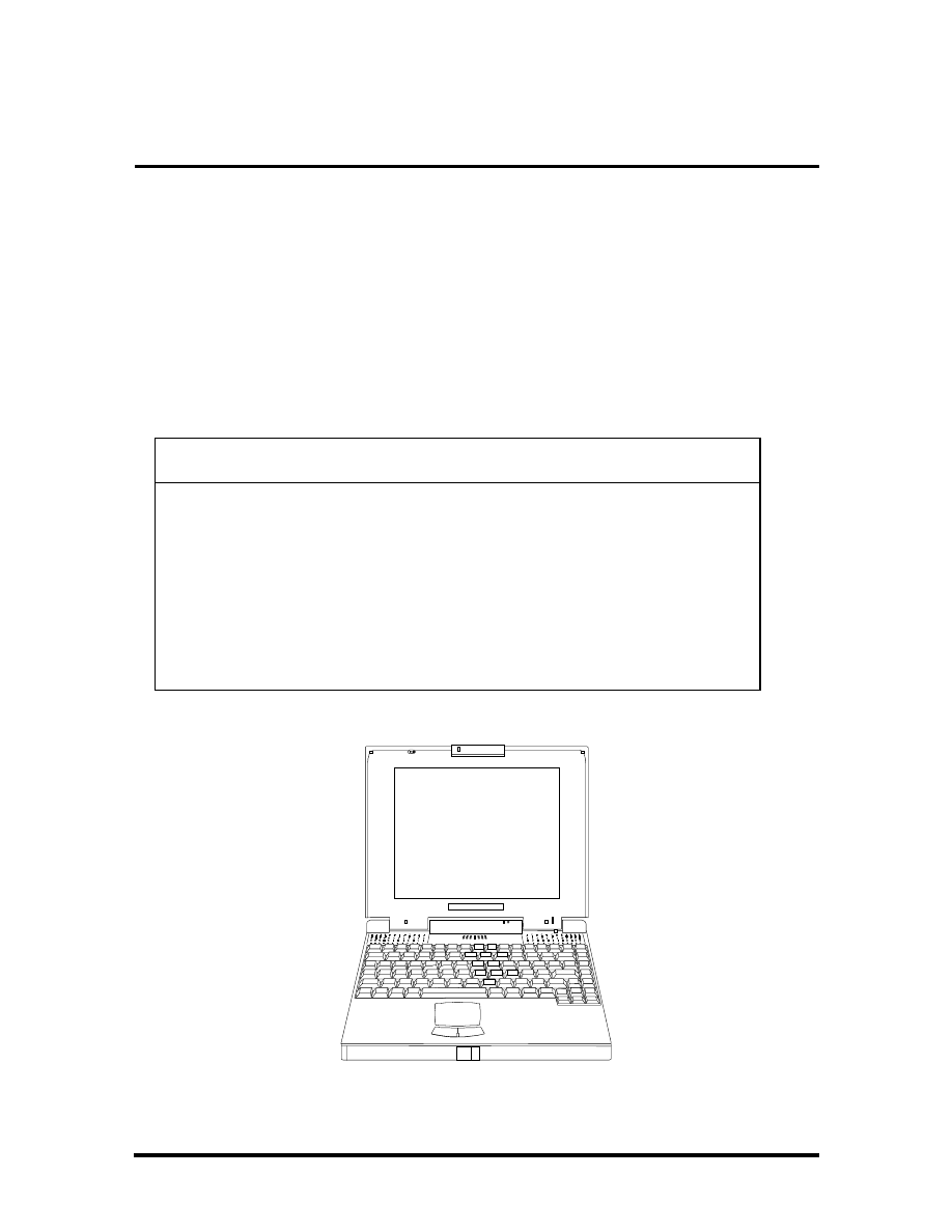
Figure 1-1 NEC Versa 2400 Series Notebook
SOLD BY laptopia2005 DO NOT RESELL!!
SOLD BY laptopia2005 DO NOT RESELL!!

1-2 Introduction
FEATURE HIGHLIGHTS
The NEC Versa 2400 notebook series includes a variety of innovative features designed to
meet the most demanding computing requirements:
Table 1-2 Feature Highlights
Features
Description
CPU
Intel P54CSLM-100MHz (Intel P54CSLM-133MHz for 243X)
processor with internal 16KB cache memory and math coprocessor
Memory
On-board 8MB RAM (16MB for NEC Versa 243XCD) and can be
upgraded to 40MB
Display
11.3” DSTN VGA Color LCD at 600 x 800 pixels resolution with 256
colors
VGA
32-bit Video PCI bus VGA controller/ 1MB RAM Video Memory /
Supports up to 1024 x 768 pixels resolution for external CRT monitor
with 256 colors
HDD
Built-in 2.5-inch IDE high capacity hard drive (12.7mm height)
FDD
Built-in 3.5-inch 1.44MB floppy disk drive
Keyboard
Built-in 87/88-key keyboard with 12 programmable function keys,
embedded numeric keypad and special function control keys,
dedicated screen control keys, and inverted “T” cursor keys / IBM
enhanced 101/102-key compatible keyboard
Pointing Device
VersaGlide
PCMCIA Slot
Two PCMCIA 2.1 card slots that support two Type II PC cards at the
same time or one Type III and one Type II PC cards at the same time
I/O Port
1 x Serial Port (w/ FIFO) / 1 x Printer Port (ECP/EPP) / 1 x VGA Port
/ 1 x PS/2 keyboard & mouse port
Power System
Auto-switching AC Adapter (90V - 264V) / Rechargeable NiMH
Battery pack / Advanced power management capabilities
SOLD BY laptopia2005 DO NOT RESELL!!
SOLD BY laptopia2005 DO NOT RESELL!!
Introduction 1-3
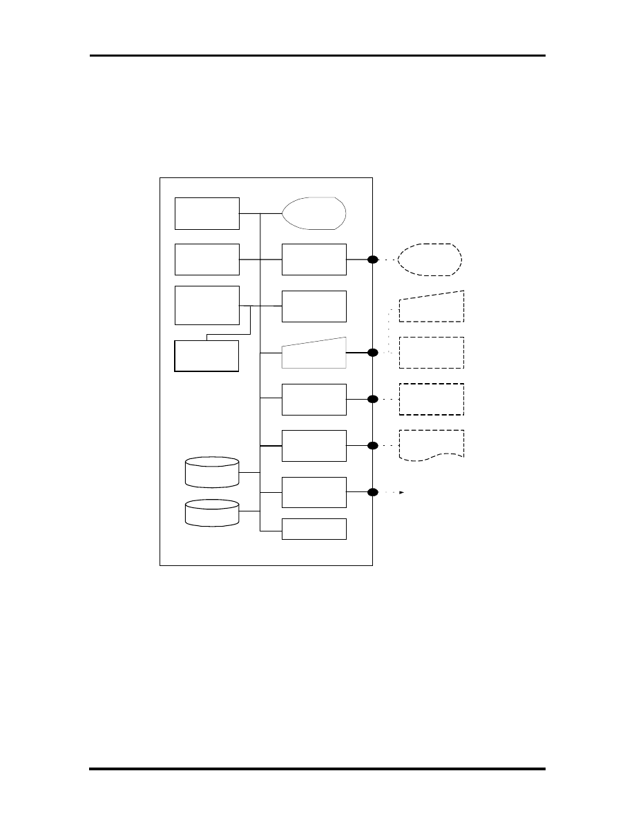
SYSTEM CONFIGURATION
The following diagram shows the NEC Versa 2400 system configuration.
I N T E L
P 5 4 C S L M ( T C P )
C P U
B I O S
F l a s h R O M
8 / 1 6 M B R A M
O n - B o a r d
Upgradable to
4 8 M B
C o l o r L C D
( 8 0 0 x 6 0 0 )
D S T N
V L B u s
Controller
( V G A )
G l i d e P a d
P o i n t i n g
D e v i c e
Serial Interface
( R S - 2 3 2 C )
Parallel
Interface
B a n k 1 ( S l o t 1 )
4 / 8 / 1 6 M B
D I M M
Built-in
H D D
P C M C I A C a r d
Slot x 2
P S / 2 K e y b o a r d
K e y b o a r d
P S / 2 M o u s e
R S - 2 3 2 C
Peripheral
Printer
3 . 5 " F D D
B a t t e r y P a c k
E x t e r n a l V G A
M o n i t o r
a n d
P C M C I A C a r d
Figure 1-2 System Configuration Diagram
SOLD BY laptopia2005 DO NOT RESELL!!
SOLD BY laptopia2005 DO NOT RESELL!!

1-4 Introduction
QUICK TOUR OF THE NOTEBOOK
Take a moment to become familiar with the locations and functions of all controls. It is rec-
ommended that you first go through the notebook’s user guide for more information on
how to operate all of the features.
Main Components
This section describes the main features of the NEC Versa 2400 computer.
Color LCD Display Panel
Both the NEC Versa 240X and 243X series have a built-in 11.3” passive matrix dual scan
DSTN color liquid crystal display (LCD) which you can adjust and tilt to your desired
viewing position. The LCD provides 800x600 pixel resolution with a maximum of 256 col-
ors, and supports simultaneous display with an external VGA monitor.
The LCD screen also uses Cold Cathode Fluorescent Tube (CCFT) backlighting which con-
sumes most of the power from the notebook. To save battery power, the system has an ad-
vanced power management feature that powers down the LCD when it has not been used
for a predetermined amount of time. You can adjust the brightness and contrast level of the
LCD by pressing the “Fn “ key (lower left corner) and the desired brightness or contrast
keys (lower right corner) at the same time.
Power Switch/LCD Cover Switch
The power switch button, when pressed, turns on the notebook’s power. Press it again to
turn computer power off. Whenever the notebook is in “Save-to-file” suspend mode, the
power switch button serves as a manual resume switch that allows you to continue your
application work at the place you last left it before the suspend mode was activated.
NOTE: Always wait for a few seconds between
turning off and turning on the power. Likewise,
check to see if the power switch is turned off
before installing the power supply.
On the top of the unit underneath the right hinge is the LCD cover switch button. This but-
ton automatically depresses and releases when you lower or raise the LCD display panel.
Depending on your power management settings, this button will either switch the notebook
to the Suspend mode or will shut off the LCD when you close the cover.
SOLD BY laptopia2005 DO NOT RESELL!!
SOLD BY laptopia2005 DO NOT RESELL!!
Introduction 1-5
NOTE: If the NEC Versa 2400 has been left un-
used for a prolonged period of time the battery
may become completely discharged. It will then
be necessary for you to reconnect the AC adapter
for approximately 30 minutes before the battery
will begin to recharge normally.
Status Panel and Power Indicator
Directly below the LCD display, in the center near the right hinge, is the Suspend Mode
LED Displays. These LEDs provide an easy way of determining what the power mode the
unit is in at the moment. Below these two LEDs is a row of seven more. These LEDs will
light to indicate whether a device is being accessed, whether an operation is being done, or
if a certain mode is or has been activated.
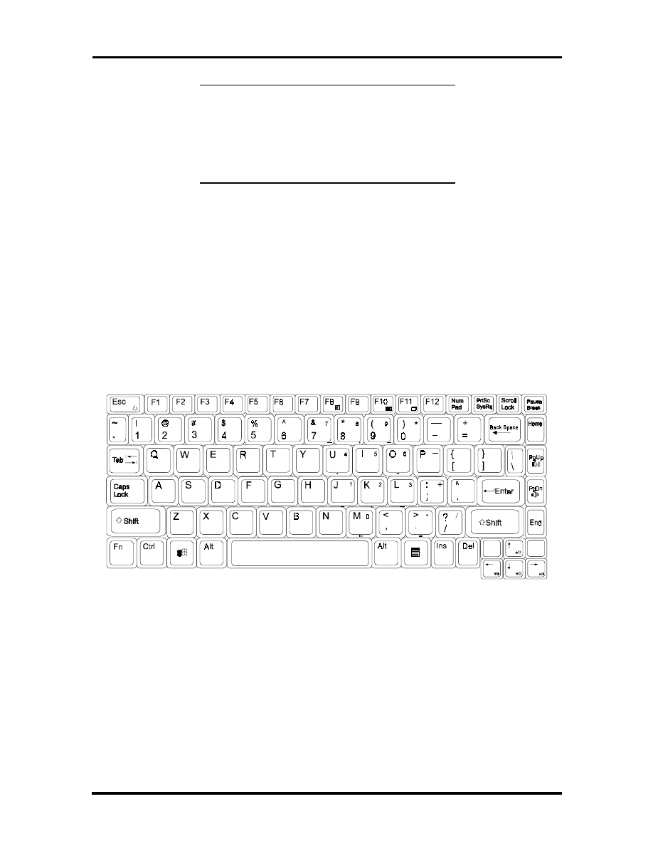
Keyboard
The notebook has a built-in 87/88-key keyboard that provides complete emulation of a full-
sized IBM AT-enhanced keyboard with function keys and screen/cursor control keys.
Figure 1-3 Standard Keyboard Layout
The notebook keyboard includes an embedded numeric keypad, and some special function
keys that are activated by pressing the
<Fn>
key together with another key. These special
function keys (more popularly known as “hot keys”) allow you to control and adjust some
of the notebook’s functions like; display controls, speaker volume, and power management
features. The embedded numeric keypad is activated by pressing the
<Num Lock>
key.
Once the <Num Lock> key is pressed the upper blue symbols will become active.
SOLD BY laptopia2005 DO NOT RESELL!!
SOLD BY laptopia2005 DO NOT RESELL!!
1-6 Introduction
NOTE: Activating the Num Lock key will in
turn disable the alphanumeric keys where the
embedded keys are located. Press the Num Lock
key again to disable the embedded keys and re-
sume normal keyboard operation.
Table 1-3 Fn Key Combination Summary
Key Combina-
tion
Function
<Fn> key +
<Esc> key
This key combination puts the system in Suspend mode.
<Fn> key +
<F8> key
This key combination mutes the speaker volume.
<Fn> key +
<F10> key
This key combination toggles between video display output to the LCD
display, to an external CRT monitor, or to a simultaneous display of
LCD and CRT.
<Fn> key +
<F11> key
This key combination toggles the LCD display backlighting (CCFT) on
and off.
<Fn> key +
<right> key
This key combination increases the contrast level.
<Fn> key +
<left> key
This key combination decrease the contrast level.
<Fn> key +
<Up> key
This key combination increase the brightness incrementally for the
LCD.
<Fn> key +
<Down> key
This key combination decreases the brightness incrementally for the
LCD.
<Fn> key +
<PgUp> key
This key combination increases the speaker volume level incremen-
tally.
<Fn> key +
<PgDn> key
This key combination decreases the speaker volume level incremen-
tally.
The notebook’s keyboard also features an embedded editing keypad, which offers an op-
tional method for editing and moving within documents. The embedded editing keys are
color coded in blue and embedded on the front side of the embedded numeric keypads. To
use these editing keys, first press the
Num Lock
key and then combine the
Shift
key + the
desired function key to enable these editing keys. When the embedded editing keys are op-
erational, the Num Lock LED will be activated. To return to normal keyboard operation,
press the
Num Lock
key again. When the Num Lock LED glows the embedded numeric
key pads are activated.
SOLD BY laptopia2005 DO NOT RESELL!!
SOLD BY laptopia2005 DO NOT RESELL!!
Introduction 1-7
VersaGlide
In front of the keyboard panel, in the center of the palm rest typing surface, is the Versa-
Glide pointing device. The buttons below the glide pad are configured (by default) as the
left and right button respectively. While the button to the right is configured as the right
button on the mouse. Moving the pointer on the screen is done by moving your finger over
the surface and directing the pointer where you want it to go. The VersaGlide is compatible
with the standard PS/2 mouse and can be activated using the normal DOS or Windows IBM
or PS/2 mouse driver.
Figure
1-4
VersaGlide
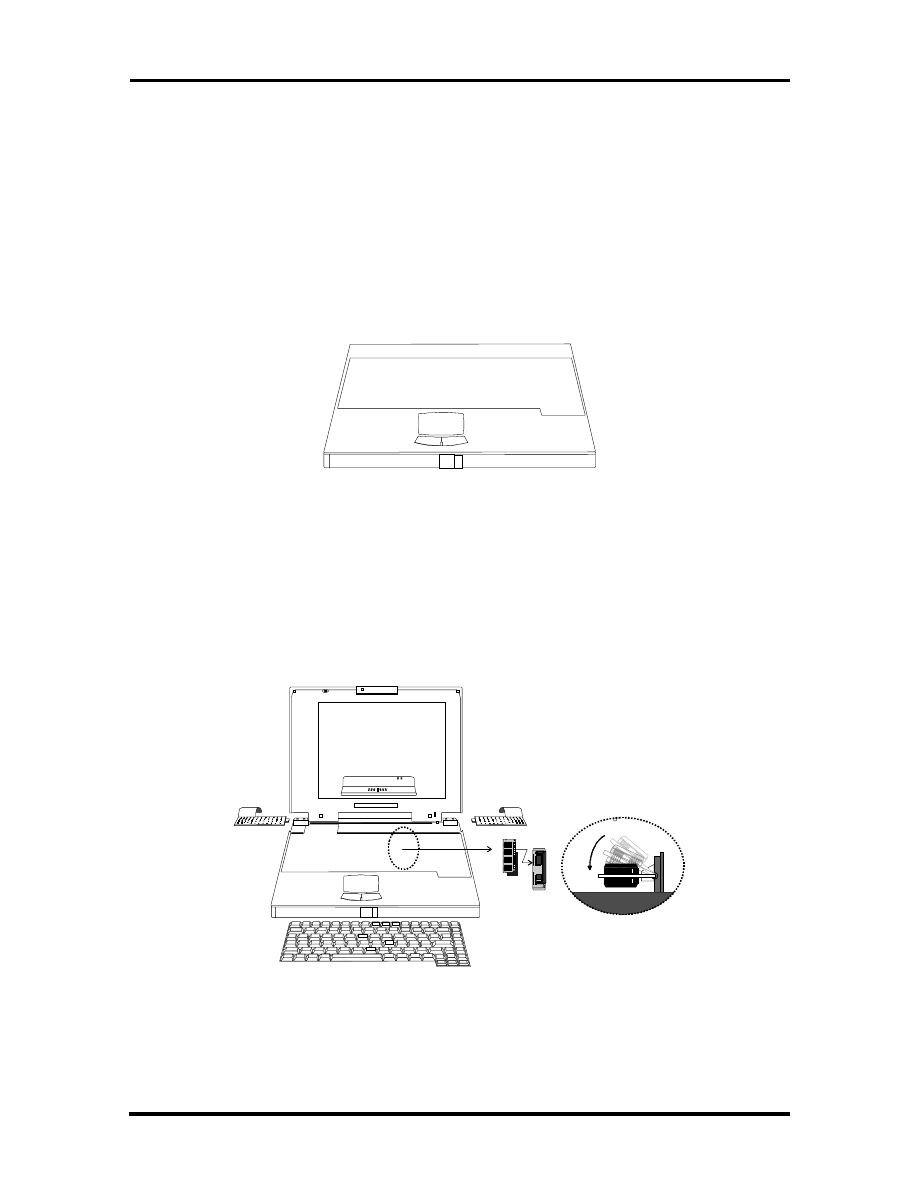
Memory Slot Compartment
The memory compartment is located just under the keyboard. Inside the compartment are
two extra memory module sockets which can accommodate any standard JEDEC 4MB,
8MB, and 16MB DIMM modules.
Figure 1-5 Memory Slot Compartment
SOLD BY laptopia2005 DO NOT RESELL!!
SOLD BY laptopia2005 DO NOT RESELL!!
1-8 Introduction
The Right Side of the Notebook
This section describes the features on the right side of the NEC Versa 2400 computer.
Built-in Floppy Disk Drive
On the right-front side of the notebook you will find the floppy disk drive which supports
3.5-inch 1.44MB high density (HD) diskettes or 720KB double-sided (DS) diskettes. Insert
the floppy diskette with the metal shutter towards the drive and the diskette label facing up.
To remove the floppy diskette, you press the eject button found on the upper right of the
floppy disk drive.
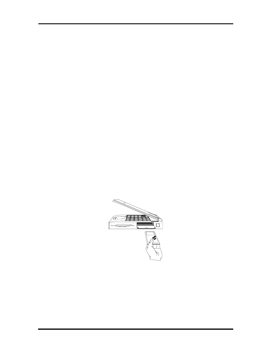
PCMCIA Slot Compartment
The PCMCIA slot compartment houses two card slots that support two PCMCIA Type II
devices or one Type III device. Open the compartment door to view the PCMCIA slots. In-
sert Type III cards into the lower slot. Insert the card with the pin sockets facing towards
the drive and the label facing up. To remove the PCMCIA card, push on the eject button to
release the pin connections and slowly pull out the card.
The NEC Versa 2400 Series also comes with DOS/Windows PCMCIA drivers for support-
ing various PCMCIA cards like modem cards, network cards, and other I/O and memory
cards. The LED Status Bar, likewise, provides lights to indicate when the computer is ac-
cessing the inserted PCMCIA cards. The upper PCMCIA slot is referred to “
Slot 0
” while
the bottom slot is referred to as “
Slot 1
”. Slot 0 always takes precedence over Slot 1 in
drive designations.
Figure 1-6 Inserting a PCMCIA Card
SOLD BY laptopia2005 DO NOT RESELL!!
SOLD BY laptopia2005 DO NOT RESELL!!
Introduction 1-9
Hard Disk Drive Compartment
Just beside the floppy disk drive, and below the PCMCIA slots, is the notebook’s internal
hard drive. The NEC Versa 2400 provides industry standard 2.5-inch IDE hard disk drive at
810MB and 1GB. The System BIOS of the notebook also includes Auto IDE detection and
LBA mode for easy installation as well as later upgrades for higher capacity disk drives.
Front of the Notebook
This section describes the features on the front side of the NEC Versa 2400 computer.
Battery Compartment
In the left front corner of the notebook is the battery compartment. It houses the recharge-
able NiMH battery pack. The battery pack begins charging whenever you connect the AC
adapter to the notebook. It is very important to always have the battery installed on the
notebook, to have it always charged. Leaving the battery pack out of the unit for a long pe-
riod of time will completely drain the battery cells.
To remove the battery pack from the compartment unit, push the battery compartment re-
lease lock and slowly pull out the battery pack.
NOTE: There are two types of battery packs for
the NEC Versa 2400 Series. The NEC Versa
240X models uses Type A battery packs with
3500mA; while the NEC Versa 243X models
uses Type B battery packs with 3500mA. Both
battery packs are not interchangeable and may
cause damage to the computer if swapped.
Figure 1-7 Removing the Battery Pack
SOLD BY laptopia2005 DO NOT RESELL!!
SOLD BY laptopia2005 DO NOT RESELL!!
1-10 Introduction
Left Side of the Notebook
The following details the left side of the NEC Versa 2400.
Figure 1-8 Left Side of the Notebook
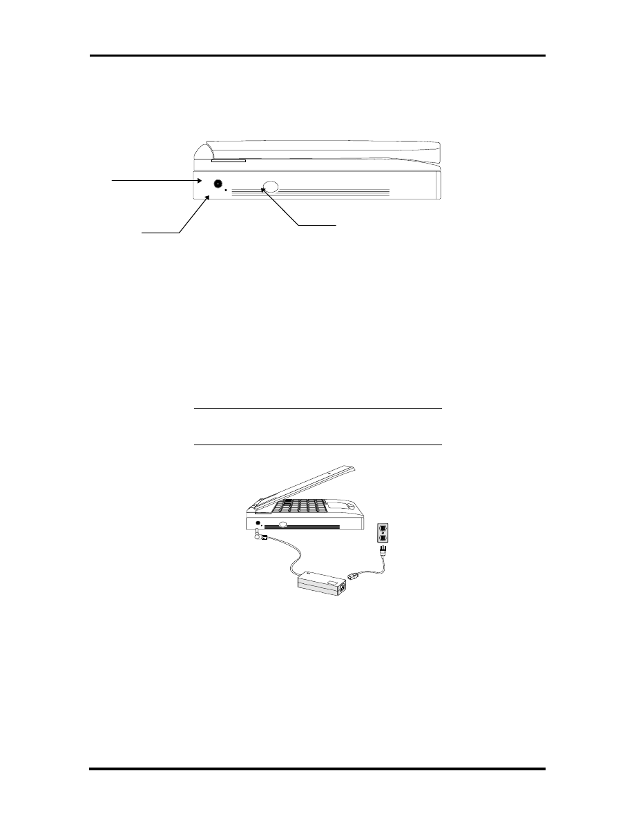
DC-IN Connector Jack
To the left of the PCMCIA compartment, you will find a connector jack for the AC. The
NEC Versa 2400 series provides a universal auto-switching AC adapter where you connect
the AC power cord and into the power outlet. It is important to have the AC adapter con-
nected to the notebook to recharge the battery and keep the notebook working continu-
ously.
NOTE: Use only the AC adapter that comes
with the NEC Versa 2400 notebook.
Figure 1-9 Connecting the AC Adapter to the Notebook
Hardware Reset Switch
To the right of the AC adapter connector jack, you will notice a small hole which allows an
easy alternative to resetting the notebook’s hardware.
DC-IN
Connector
Reset Switch
Power Switch
SOLD BY laptopia2005 DO NOT RESELL!!
SOLD BY laptopia2005 DO NOT RESELL!!
Introduction 1-11
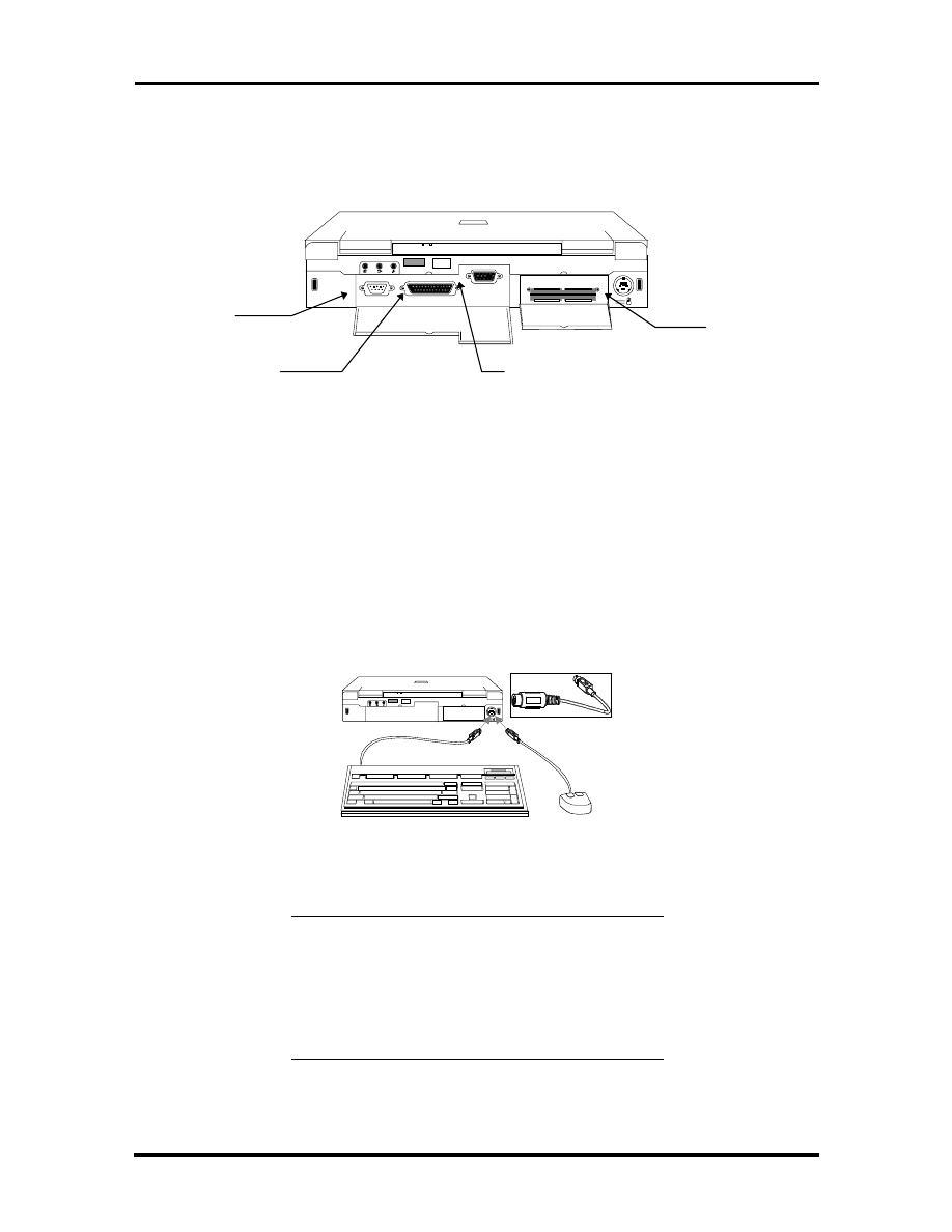
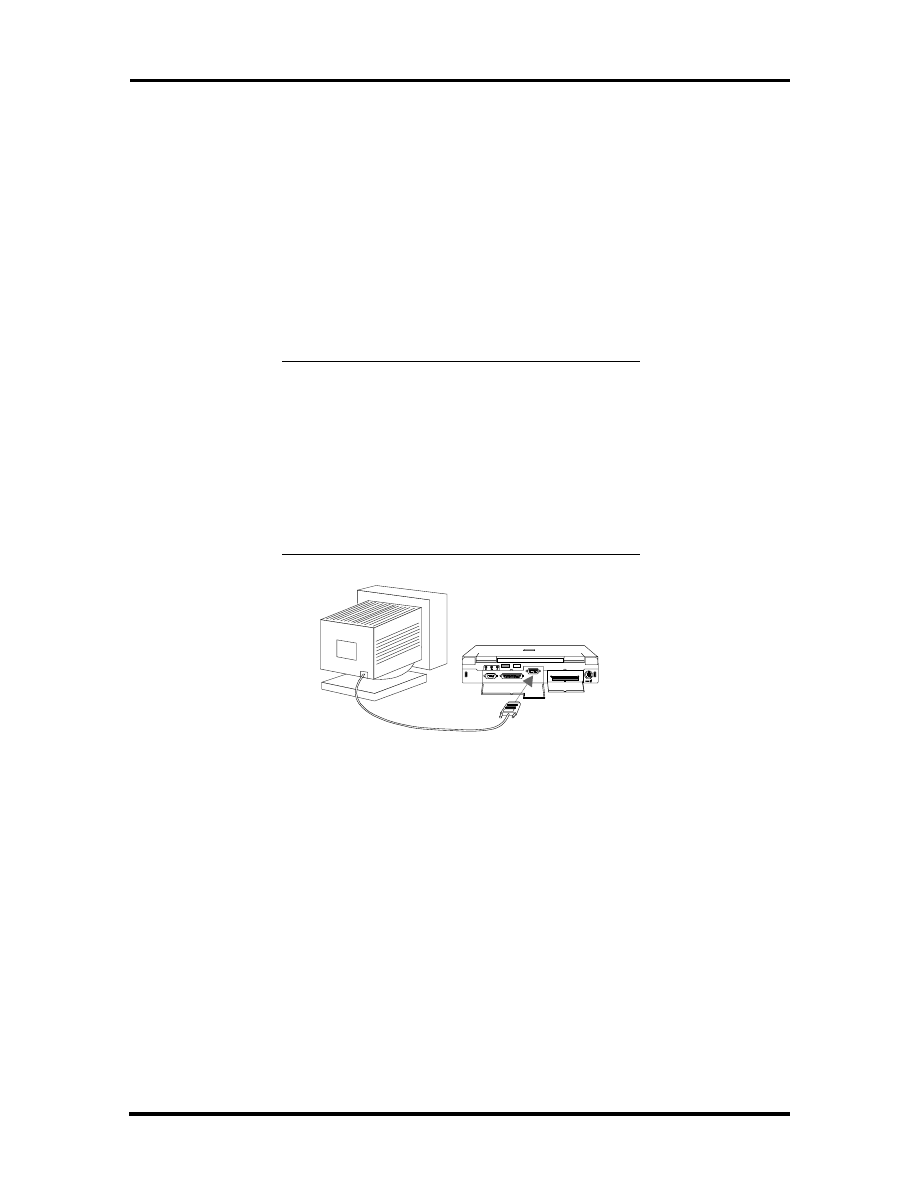
The Rear of the Notebook
The following details the rear side of the NEC Versa 2400.
Figure 1-10 The Rear Side of the Notebook
External Keyboard and PS/2 Mouse Port
The external keyboard and PS/2 mouse port allows you to connect an external full-sized
IBM AT-enhanced keyboard. When an external keyboard is connected, both the built-in
keyboard of the notebook and the external keyboard can be used simultaneously.
The NEC Versa 2400 also provides a Y-connector adapter allowing simultaneous use of an
external AT-enhanced keyboard and a PS/2 mouse. When the external PS/2 mouse is con-
nected using the Y-connector, the built-in VersaGlide is disabled.
Figure 1-11 Connecting External Keyboard and PS/2 Mouse
NOTE: When connecting an external PS/2
mouse, it is required that you power off the
computer first before connecting the PS/2
mouse. This way, the system can detect the ex-
ternal PS/2 mouse and disable the built-in Ver-
saGlide.
Serial Port
Parallel Port
VGA Port
Ext. K/B and
PS/2 Mouse
Port
SOLD BY laptopia2005 DO NOT RESELL!!
SOLD BY laptopia2005 DO NOT RESELL!!
1-12 Introduction
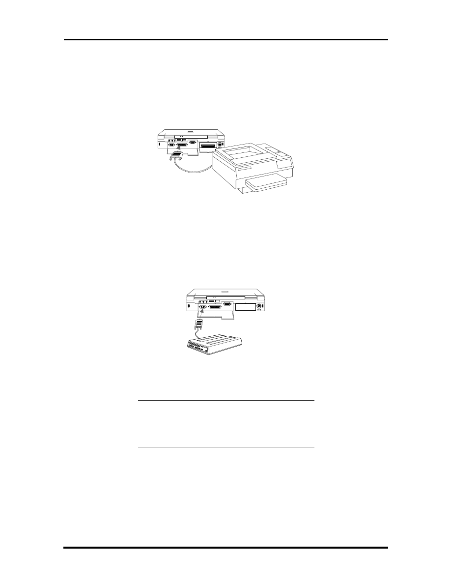
VGA Port
The 15-pin female VGA connector allows you to connect an external VGA monitor that
supports up to 1024x768 pixels resolution. When displaying on the external VGA monitor
alone, the VGA port can support resolution at 800x600 at 256 colors and 1024x768 at 16
colors for the NEC Versa 2400 and 640x480 at 64K colors, 800x600 at 256 colors, and
1024x768 at 256 colors for both the NEC Versa 2400 and 2430.
The NEC Versa 2400 series provides a VGA VESA driver diskette for installing different
display resolution drivers for Windows Setup. You can also toggle the display between the
LCD and the external monitor by pressing the
<Fn>
key +
<F10>
key combination.
NOTE: Even when set to 800x600 or 1024x768
resolution, the external monitor will only show
800x600 resolution if the computer is running at
Simultaneous display. You need to toggle the
display to the external monitor only in order to
display higher resolution.
Refer also to Appendix A for a list of supported
video modes.
Figure 1-12 Connecting an External Monitor
SOLD BY laptopia2005 DO NOT RESELL!!
SOLD BY laptopia2005 DO NOT RESELL!!
Introduction 1-13
Printer Port
The 25-pin printer port provides a parallel interface to connect a parallel printer or pocket
network adapter. Many operating systems and software applications refer to this port as
LPT1. You can run the BIOS SETUP program to change the configuration of the parallel
port to Standard or Bi-directional.
Figure 1-13 Connecting to the Printer Port
Serial Port (COM 1)
The 9-pin serial port provides a serial interface for a RS-232C device such as external serial
modem. This port is commonly referred to as COM1.
Figure 1-14 Connecting to the Serial Port
NOTE: First power off the system before con-
necting an external serial device. After turning on
the power again, run the BIOS SETUP program
if needed.
SOLD BY laptopia2005 DO NOT RESELL!!
SOLD BY laptopia2005 DO NOT RESELL!!

1-14 Introduction
Bottom of the Notebook
The following details the bottom of the NEC Versa 2400.
Battery Module Handle and Lock
To release the battery module from its compartment, push the battery compartment latch as
indicated by the arrow marked on it. While doing this, hold the handle of the battery module
and slowly pull it out from its compartment.
ROM Memory Compartment Cover
The ROM memory compartment cover is secured by tabs. Lift the cover with your finger-
nail to open this cover. Inside is the ROM chip. It is not neccessary to remove this cover
while performing normal service operations.
SYSTEM BIOS SETUP PROGRAM
This section provides the outline features and operation of the Phoenix BIOS Setup pro-
gram used in the NEC Versa 2400 Series. The BIOS (Basic Input-Output System) Setup
program allows you to change the system configuration settings such as the current date
and time, the disk drive and ports settings, and the power management as well.
As POST (Power-On Self Test) executes during boot up process, the screen will display the
following message:
Press F2 to Enter SETUP
SOLD BY laptopia2005 DO NOT RESELL!!
SOLD BY laptopia2005 DO NOT RESELL!!
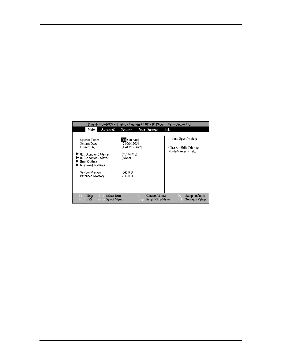
Introduction 1-15
Press the
F2
key to run the BIOS Setup program. The BIOS Setup program is organized
into two pages of menus. Change settings using the PgDn and PgUp keys. To move from
one option to another, you use the up and down arrow keys while using the spacebar and
-
keys to change the settings.
To exit the BIOS Setup program, simply press the
Esc
key and select from the pop-up
window whether you want to load the default values for all fields; save your changes and
exit; or exit without saving any changes.
THE BOOT SETUP MENU
The boot setup menu allows you to change the following configurations:
Figure 1-15 The Bootup Setting Menu
The boot setup menus let you configure system settings as listed in the following tables.
SOLD BY laptopia2005 DO NOT RESELL!!
SOLD BY laptopia2005 DO NOT RESELL!!
1-16 Introduction
Table 1-4 Boot Main Setup Menu
Item
Function
System Time
This option allows you to change the system time, using the
format hour : minute : second. You can change the system
time here or from your operating system’s command prompt.
System Date
This option allows you to change the system date, using the
format month day, year. You can change the system date
here or from your operating system’s command prompt.
Diskette A
This option allows you to specify the type of diskette drive
mounted inside the notebook. The default setting for this
option is 3.5”, 1.44MB disk drive.
HDD LBA Mode
The NEC Versa 2400 supports LBA (logical block addressing)
mode which is Enabled automatically for large capacity hard
drives over DOS’ limit of 528MB.
Hard Disk
This option allows you to specify the type of hard drive
mounted inside the notebook.
Select the Auto option to instruct the BIOS to automatically
detect the relevant parameters of the hard drive.
Some hard drives, however, do not respond correctly to the
values detected. In such cases, you must search and select,
from the list, the make and model of the drive being used.
Base Memory
This field reports the amount of base (or conventional)
memory found by the BIOS during its POST. The value
should not exceed or go below 640KB.
Extended Memory
This field reports the amount of extended memory found by
the BIOS during POST. The value displayed is the amount of
the memory address map. Because all models in the NEC
Versa 2400 series have a minimum of 8MB of memory as the
standard configuration, this value should not be less than
3072KB.
Boot Sequence
This option allows you to configure the computer to which
drive it will first try to look for the operating system.
Select A: then C: if you want to boot from a diskette. If there
is no diskette found in the floppy drive, the computer will then
try to load the operating system from the hard drive.
Select C: then A: if you want to boot from a hard drive. If
there is no operating system found in the hard drive the
computer will try to load the operating system from a floppy
drive.
Select C: only if the hard drive already holds an operating
system and all necessary startup file configurations.
Num Lock
This option allows you to toggle the Num Lock key on or off.
Keyboard Repeat
Rate
This option allows you to select the auto-repeat key speed.
Possible values include 2, 6, 10, 13.3, 18.5, 21.8, 26.7, or 30
seconds.
SOLD BY laptopia2005 DO NOT RESELL!!
SOLD BY laptopia2005 DO NOT RESELL!!
Introduction 1-17
Table 1-5 Boot Setup Peripherals Menu
Item
Function
Serial Port
This option allows you to configure the notebook’s serial port
as either (3F8-IRQ4), (2F8-IRQ3), (3E8-IRQ4), (2E8-IRQ3),
or none. The default setting is (3F8-IRQ4).
Infrared Serial Port
This option allows you to configure the notebook’s infrared
serial port as either (3F8-IRQ4), (2F8-IRQ3), (3E8-IRQ4),
(2E8-IRQ3), or none. The default is (2F8-IRQ3).
Parallel Port
This option allows you to configure the notebook’s parallel
port as either (378-IRQ5), (3BC-IRQ7), (278-IRQ5), (378-
IRQ7), or none. The default is (378-IRQ7).
Parallel Mode
This option allows you to configure the notebook’s parallel
mode as either Unidirectional, Bi-directional, Enhanced, or
ECP. The default is ECP.
Diskette Controller
This option allows you to disable the floppy disk controller.
IDE Adapter
This option allows you to disable the IDE adapter.
Table 1-6 Boot Setup Security Menu
Item
Function
Password
This option allows you to limit access to the computer through
the use of a password. If you select this option, a pop-up win-
dow will appear asking you to set or change the password. A
password can be up to seven characters in length, and is
cleared by eliminating the password with the F1 key.
Note: If you forget the password of the computer, the
only way to access the system again is to discharge the
CMOS battery. See note below.
Set Password
Press
<Enter>
to enter the Password.
Password on Boot
This option allows you to configure the Password to be en-
abled at the operating system level.
Password on Re-
sume
This option allows you to configure the Password to be en-
abled when resuming from the suspend mode.
The CapsLock and ScrollLock LED’s will flash in sequence for
30 seconds, indicating that the password is required to re-
sume. The LED’s will start flashing again as soon as a key is
hit until a password is entered.
NOTE: You can discharge the CMOS battery by
simply unplugging the RTC CMOS battery from
the connector CN11 of the motherboard. You
must wait for 10 minutes before plugging in the
battery again.
SOLD BY laptopia2005 DO NOT RESELL!!
SOLD BY laptopia2005 DO NOT RESELL!!

1-18 Introduction
Table 1-7 Boot Setup Power Savings Menu
Item
Function
Power Saving
This option allows you to enable or disable power manage-
ment.
Select
Disabled
, all other power management settings are ig-
nored and disabled as well.
Select
Disabled ON AC
, the power management is disabled
only when the computer is powered by the AC adapter, but
will enable the power management while on battery.
Select Enabled, the power management is enabled all the
time.
Standby Time-out
This option allows you to specify the length of time the system
will be in the Idle Mode before entering the Standby Mode.
Standby Mode Places the Serial, infrared and parallel ports,
floppy drive, and hard drive into a power saving mode.
Possible values include
Disabled, 1, 2, 4, 8,
or
16 minutes.
Auto Suspend
Time-out
This option allows you to specify the length of time the system
will be in the Standby Mode before entering the SUSPEND
Mode.
Possible values include
Disabled, 1, 2, 4, 8,
or
16 minutes.
SUSPEND Mode
This option allows you to enable SUSPEND Mode.
Select
Save to File
, the computer will save data to the hard
drive.
It is important to have a hidden file on the hard drive when
enabling this; otherwise an error message will appear on the
display screen when the system restarts.
Select
SUSPEND
, the computer will save data to RAM
The computer will switch to the SUSPEND Mode after the
preset time of inactivity. During this SUSPEND Mode the
computer becomes inactive, all devices are in SUSPEND
Mode, and the CPU is powered off.
SOLD BY laptopia2005 DO NOT RESELL!!
SOLD BY laptopia2005 DO NOT RESELL!!

Introduction 1-19
Table 1-7 Boot Setup Power Savings Menu
Item
Function
Hard Disk Time-out
This option allows you to select a specific time-out value after
which power to the hard drive is shut down. Possible values
include
Disabled
,
1
,
2
, 4, 8, or
16 minutes
.
When not disabled, the hard drive will shut off after the preset
time of inactivity. The hard drive will activate again when the
system tries to access it; this may cause a slight delay in the
computer’s operation as it waits for the hard drive to power up
again.
Set this option to
Disable
if you want the hard drive to always
be spinning.
Video Time-out
This option allows you to specify a length of time the key-
board and mouse is inactive before the screen is turned off.
Possible values include
Disabled, 1, 2, 4 ,8,
or
16 minutes.
Note: If you use “screen saver” software, the Video Monitor
should be set to
Disabled
.
Cover Switch Con-
trol
This option allows you to effectively program the type of event
which occurs when the display panel is closed.
Select
SUSPEND
, the computer enters the SUSPEND Mode
when the LCD Panel is closed.
Select
Backlight Off
, the system will power down the LCD
when the LCD Panel is closed.
Serial Port Ring Re-
sume
This option allows you to resume the system if an incoming
call is received from the serial port modem.
Select
Off
, the computer will not resume.
Select
On
, the computer will resume.
This feature does not apply to PCMCIA port modems.
SYSTEM UPGRADES
The NEC Versa notebook is easily upgradable to a higher capacity hard drive. In addition,
you can add an optional second memory modules to increase the system memory to as
much as 48MB. This section provides the settings needed as well as illustrations for upgrad-
ing the system.
MEMORY UPGRADE PROCEDURE
The NEC Versa notebook allows you to install and expand the on-board 8MB system
memory via the memory compartment found under the keyboard. Inside the compartment is
an extra memory module socket which can accommodate any standard JEDEC 4MB, 8MB,
and 16MB DIMM modules.
SOLD BY laptopia2005 DO NOT RESELL!!
SOLD BY laptopia2005 DO NOT RESELL!!
1-20 Introduction
For NEC Versa 2400 Series Notebooks, the following memory configurations are applica-
ble:
Table 1-8 8 MB Memory Configurations
On-Board Memory
Extra Socket
Total Memory
8MB
empty
8MB
8MB
8MB
16MB
8MB
16MB
24MB
8MB
24MB
32MB
8MB
32MB
40MB
Table 1-9 16 MB Memory Configurations
On-Board Memory
Extra Socket
Total Memory
16 MB
empty
16 MB
16 MB
8 MB
24 MB
16 MB
16 MB
32 MB
16 MB
32 MB
48 MB
To upgrade the memory in the notebook, follow the steps mentioned below:
1.
Power off the computer and remove the AC adapter and battery pack.
2.
Remove the hinge covers, status bar cover, and the keyboard from the top of the
unit and locate the memory expansion sockets.
3.
Remove the extra DIMM module from its anti-static wrapping.
4.
Hold the memory module with its golden teeth connector pointed towards the
memory socket. Incline the module at 60-degreesand gently attached it to the
memory socket by pushing it forward.
5.
Slowly push the module downwards until the locking tabs snap into the retaining
notches or holes at each corner of the module.
6.
Replace the keyboard, status bar cover, and hinge covers.
7.
Reconnect the AC adapter and reattach the battery pack to the computer.
SOLD BY laptopia2005 DO NOT RESELL!!
SOLD BY laptopia2005 DO NOT RESELL!!

Introduction 1-21
8.
Power on the notebook and notice the BIOS error message informing you that the
memory size stored in CMOS does not match the installed memory size. Press
F2
to run the SETUP program and save the CMOS settings anew. The computer will
automatically adjust the memory size.
NOTE: If the notebook has been configured for
save-to-disk, it may be necessary to run PHDisk
to re-partition the drive. The save-to-disk parti-
tion must be of a size sufficient to store the con-
tent of the whole memory size.
SYSTEM BIOS UPGRADE PROCEDURE
The NEC Versa 2400 Series supports the EPROM Flash BIOS that allows you to easily
update the system BIOS using the Flash Programming utility program called
“
PHLASH.COM & PLATFORM.BIN
”. Update the system BIOS whenever you are up-
grading the LCD Panel or adding modifications to the computer’s hardware function. To
upgrade the System BIOS:
1.
Copy the
PHLASH.COM & PLATFORM.BIN
BIOS utility program and the
BIOS ROM file to the hard disk subdirectory. You can also choose to run the
program from the floppy diskette.
2.
Disable EMM386 or other memory manager programs before restarting the com-
puter. When booting the DOS, press
F5
to bypass the CONFIG.SYS and
AUTOEXEC.BAT. You may also choose to boot from Drive A: with a clean
DOS diskette.
3.
At the DOS prompt, type “
PHLASH <
BIOSfilename
.ROM>
” to activate Flash
BIOS programming utility. The computer will then prompt you again before
starting to update the system BIOS. After programming is complete, the system
will prompt you to reboot the computer to activate the new system BIOS.
SOLD BY laptopia2005 DO NOT RESELL!!
SOLD BY laptopia2005 DO NOT RESELL!!

Section 2
General Specifications
The following table lists NEC Versa 2400 Series system specifications.
Table 2-1 NEC Versa 2400 Series Specifications
ITEM
SPECIFICATION
CPU
Pentium P54CSLM-100MHz
TCP Package
Pentium P54CSLM-133MHz
TCP Package
System RAM
8MB On-board
Upgradeable to 40 MB on 240X model or 48 on 243X model
Memory Modules: 8MB/16MB/24MB/32MB
RAM Module Slot
Two Slots
System
Management
2M (256K x 8) Flash BIOS:
Includes System and VGA
Shadow BIOS Capability
Power
Management
Operation Modes:
Full On Mode
Doze Mode
Standby Mode
5V Suspend Mode
0-volt Suspend Mode
Peripheral Automatic Power Down
Cover Switch Support
SOLD BY laptopia2005 DO NOT RESELL!!
SOLD BY laptopia2005 DO NOT RESELL!!

2-2 General Specifications
Table 2-1 NEC Versa 2400 Series Specifications
ITEM
SPECIFICATION
Hard Disk Drive
Removable HDD Module
2.5-inch format / 12.7mm high
Enhanced IDE Interface
Support IDE PIO mode up to MODE 4
Support IDE MASTER MODE
810MB/1GB
CD-ROM
Removable CD-ROM Module
6x speed
Floppy Disk Drive
Removable FDD Module
720KB/1.44MB Mode Support (Overseas version)
Display
11.3” DSTN Color LCD Module:
800 x 600 in 256 colors
External CRT Capability:
640 x 480 in 64K colors
800 x 600 in 64K colors
1024 x 768 in 256 colors
LCD / CRT Display Simultaneously
32-bit PCI Bus
LCD / CRT Auto-Sense
32-bit Graphics Engine
Video RAM
1MB as Standard
5V EDO 60NS DRAM 40-Pin SOJ
PCMCIA Slots
Two Type II slots or one Type III slot
PCMCIA Socket compatible with CARD BUS standard
Pointing Device
Glide Pad
PS/2 Interface
Keyboard
Keyboard Layout:
US Layout - 87 Keys
European Layout - 88 Keys
SOLD BY laptopia2005 DO NOT RESELL!!
SOLD BY laptopia2005 DO NOT RESELL!!

General Specifications 2-3
Table 2-1 NEC Versa 2400 Series Specifications
ITEM
SPECIFICATION
Hot-Key
Operation
Fn + F8 = Volume Mute
Fn + Esc = Suspend Control
Fn + <right> = Contrast Up
Fn + <left> = Contrast Down
Fn + <Up> = Brightness Up
Fn + <Down> = Brightness Down
Fn + PgDn = Decrease Speaker Volume
Fn + PgUp = Increase Speaker Volume
Fn + F10 = CRT/LCD/Simul.
Fn + F11 = Backlight On/Off
I/O Port
25-pin Parallel Port
9-pin Serial Port
15-pin VGA Monitor Port
External Keyboard or PS/2 Mouse Port
NEC Y-Cable Support
DC-IN Jack
IR Port
Port Replicator
Support GAME port
TV out
External Keyboard
External PS/2 Mouse
Serial Port (COM1)
Printer Port (LPT1)
SOLD BY laptopia2005 DO NOT RESELL!!
SOLD BY laptopia2005 DO NOT RESELL!!

2-4 General Specifications
Table 2-1 NEC Versa 2400 Series Specifications
ITEM
SPECIFICATION
Audio
Support external Stereo Headphone Jack
Support external Stereo Line-In Jack
Support external MIC. Jack
Two Built-in speakers
Built in microphone
Status Indicator
LED Display
External LED
Power ON & Battery Low (Blanking)
5V Suspend Mode (Blanking)
Internal LED
Battery Charge
PCMCIA A/B Slot - Read / Write
HDD / FDD / CDROM - Read / Write
PMU - Enable
Num Lock - Enable
Caps Lock - Enable
Scroll Lock - Enable
Power Supply
AC Adapter
AC 100V to 240V, 47/63Hz, 36W (Max)
Constant Power Output
Dimensions: 120 (L) x 60 (W) x 36 (H) mm
Battery Input
Battery A: 10 long A-size 3500mA/hr Ni-MH Battery Cells, 12V
(Total - 42W)
Battery Fast Charge (Single Battery Pack)
Machine On: 6 hours maximum
Machine Off: 3 hours maximum
Heat Dissipation
Heat Pipe
Dimension
297mm (L) x 240mm (W) x 50.8mm (H)
SOLD BY laptopia2005 DO NOT RESELL!!
SOLD BY laptopia2005 DO NOT RESELL!!

General Specifications 2-5
Table 2-1 NEC Versa 2400 Series Specifications
ITEM
SPECIFICATION
Optional Items
External Battery Charger
Port Replicator
Key Components
11.3” Color DSTN SVGA LCD: LMG9910ZWCC Hitachi
CD-ROM:
CDR-N16-P Sanyo, or
CD-46E TEAC
810MB HDD or 1GB HDD
FDD, NEC FD1238H
Keyboard:
87/88 Key Full Size (Win95)
Controller: Mitsubishi M38813M4
Glide Pad:
TM1002S-D Synaptics
Battery:
Sanyo Ni-MH 1.2V, LA, HR 4 / 3
Audio Amplifier: ROHM BA7786FP
Micro Controller: Micro Chip PIC16C62
Clock:
Generator: ICS AV9154-43
Buffer: NS CGS74CT2524 & CGS74CT2525
Core Logic:
UMC 8891BF-N
UMC 8892BF-N
UMC 8886BF-N
VGA Chip: C&T 65548
Super I/O: NS PC87336VLJ
PCMCIA
Controller: Omega 82C094
Decoder: Omega OM82C28
Power Switch: Micreel MIC2563-1
BIOS: Phoenix
IR Chip: TemicTFDS3000
Audio Chip: ESS 1788
Regulor: NS LP2952
RS232 Driver: MAXIUM MAX213
Flash ROM: AMD AM29F002T
PWM Controller: MAXIUM MAX797
SOLD BY laptopia2005 DO NOT RESELL!!
SOLD BY laptopia2005 DO NOT RESELL!!

2-6 General Specifications
PRODUCT MIX
The following table lists the NEC Versa 2400 Series product mix.
Table 2-2 Product Mix
240XD (RT4)
240XCD (RT4CD)
243XCD (RT4CD)
CPU
Pentium / 100MHz
P54CSLM(TCP) /
Intel
Pentium / 100MHz
P54CSLM(TCP) /
Intel
Pentium / 133MHz
P54CSLM(TCP) /
Intel
On-Board DRAM
8 MB
8 MB
16 MB
Video RAM
1 MB
1 MB
1 MB
HDD
810 MB
1 GB
1 GB
LCD
11.3” DSTN LCD
11.3” DSTN LCD
11.3” DSTN LCD
FDD
Removable
Removable
Removable
CD-ROM
None
6X
6X
Battery Pack
Type A
3500mAH NiMH
Type A
3500mAH NiMH
Type A
3500mAH NiMH
Pointing Device
Glide Pad
Glide Pad
Glide Pad
PCMCIA
2 x Type II / 1 x Type
III
2 x Type II / 1 x Type
III
2 x Type II / 1 x Type
III
Keyboard
87/88 Keyboard
(Win95)
87/88 Keyboard
(Win95)
87/88 Keyboard
(Win95)
EPP/ECP Parallel
Yes
Yes
Yes
Serial Port
Yes
Yes
Yes
VGA Port
Yes
Yes
Yes
PS/2 Port
Yes
Yes
Yes
DC-in Jack
Yes
Yes
Yes
Audio Port
Yes
Yes
Yes
IR Port
Yes
Yes
Yes
Expansion Port
Yes
Yes
Yes
Power Code
Yes
Yes
Yes
SOLD BY laptopia2005 DO NOT RESELL!!
SOLD BY laptopia2005 DO NOT RESELL!!

General Specifications 2-7
SYSTEM BOARD SPECIFICATIONS
The following table lists system board specifications.
Table 2-3 Main Board Specifications
ITEM
SPECIFICATION
Clock
∗
NS Clock Buffer CGS74CT 2524
CPU
∗
PGA Socket
DRAM
∗
1M x 16-bit DRAM x 4
Video RAM
∗
256K x 16-bit DRAM (5V / 60ns), SOJ x 2
System Chipset
∗
UMC UM8891BN, 208 Pin, PQFP
∗
UMC UM8892BN, 208 Pin, PQFP
VGA
∗
C&T 65548, 208 Pin, PQFP
PCMCIA
∗
Omega 82C094, 208 Pin, TQFP
∗
Omega 82C028, 28 Pin SOIC
Internal
Connector &
Socket
To System PCB:
100 Pin, AMP
To HDD:
50 Pin, KEL
To CDROM:
40 Pin, KEL
2 Pin, Molex
To Transfer PCB:
2 Pin, Molex
To DC Converter
32 Pin, Suyin
External
Connector
COM1:
9 Pin, Suyin
Printer:
25 Pin
Docking:
160 Pin
PCB
Thickness: 1.2mm
Layers: 8
SOLD BY laptopia2005 DO NOT RESELL!!
SOLD BY laptopia2005 DO NOT RESELL!!
2-8 General Specifications
TRANSFER BOARD SPECIFICATIONS
The following table lists Transfer board specifications.
Table 2-4 Transfer Board Specifications
ITEM
SPECIFICATION
Internal Connector
To FDD:
100 Pin, AMP
To second battery
100Pin, AMP
PCB
Thickness: 1.2mm
Layers: 4
CONVERTER BOARD SPECIFICATIONS
The following table lists Converter board specifications.
Table 2-5 Converter Board Specifications
ITEM
∗
SPECIFICATION
Internal Connector
To I/O PCB:
32 Pin, Suyin
To 1
st
Battery:
10 Pin, Suyin
External Connector
To Y-Cable Connector:
32 Pin, Suyin
To AC Adapter
2 Pin
PCB
Thickness 1.2mm
Layers: 6
SOLD BY laptopia2005 DO NOT RESELL!!
SOLD BY laptopia2005 DO NOT RESELL!!

General Specifications 2-9
LED INDICATOR BOARD
The following table lists LED indicator board specifications.
Table 2-6 LED Indicator Board Specifications
ITEM
SPECIFICATION
Internal Connector
To System PCB
50 Pin, Suyin
To System PCB
40 Pin, Suyin
To LCD Panel
50 Pin, KEL
To Inverter
8 Pin, Molex
To Left Speaker
2 Pin, Molex
To Right Speaker
2 Pin, Molex
External Connector
To Headphone
5 Pin, Suyin
To Line-In
5 Pin, Suyin
To LCD Panel
41 Pin, KEL
To IR
8 Pin, Temic
To USB
4 Pin, AMP
SOLD BY laptopia2005 DO NOT RESELL!!
SOLD BY laptopia2005 DO NOT RESELL!!

2-10 General Specifications
I/O BOARD
The following table lists I/O board specifications.
Table 2-7 I/O Board Specifications
ITEM
SPECIFICATIONS
Clock
Crystal 14.318MHz, DIP Type
Crystal 32.768KHz, DIP Type
Crystal 4MHz, DIP Type
Generator:
AV9154-43, SOP 16 Pin
ROM
Flash ROM for BIOS
256K x 8, 150ns
System Chip Set
UMC UM8886BN, 208 Pin, PQFP
Super I/O
NS87336, 100 Pin, PQFP
Keyboard Controller
Mitsubishi 38813M4, 64 Pin, QFP
Micro Controller
PIC16C62, 28 Pin, SOIC
RCT Battery
VARTA 60mA, 3.6V NiMH Battery
Audio
ES17888 Sound Chip, 100 Pin, PQFP
Amplifier
ROHM BA77786FS, 25 Pin, SOIC
SOLD BY laptopia2005 DO NOT RESELL!!
SOLD BY laptopia2005 DO NOT RESELL!!

General Specifications 2-11
Table 2-7 I/O Board Specifications
ITEM
SPECIFICATIONS
Internal Connector
To System PCB
100 Pin, AMP
To System PCB
100 Pin, AMP
To HDD Unit
50 Pin, KEL
To CD ROM Unit
40 Pin, KEL
To RTC Battery
2 Pin, Molex
To Transfer PCB
40 Pin, Suyin
To DC Converter
32 Pin, Suyin
External Connector
COM1
9 Pin, Suyin
Printer
25 Pin, Suyin
Docking
160 Pin, Berg
PCB
Thickness: 1.2 mm
Layers: 6
SOLD BY laptopia2005 DO NOT RESELL!!
SOLD BY laptopia2005 DO NOT RESELL!!

2-12 General Specifications
LCD INVERTER BOARD
The following table lists LCD inverter board specifications.
Table 2-8 LCD Inverter Board Specifications
ITEM
Specification
Color Inverter
Hitachi 11.3” DSTN
LMG9910ZWCC
Input Voltage
8V to 20V
Output Voltage
500VAC Max.
Contrast Voltage
28V ~ 31V
Output Load Current
6mA (Max.)
Brightness Control
VR Type (Lower)
Contrast Control
VR Type (Upper)
Efficiency
70% Min.
Unit Size (L x W x H)
146 (L) x 22.5(W) x 9.5 (H)
SOLD BY laptopia2005 DO NOT RESELL!!
SOLD BY laptopia2005 DO NOT RESELL!!
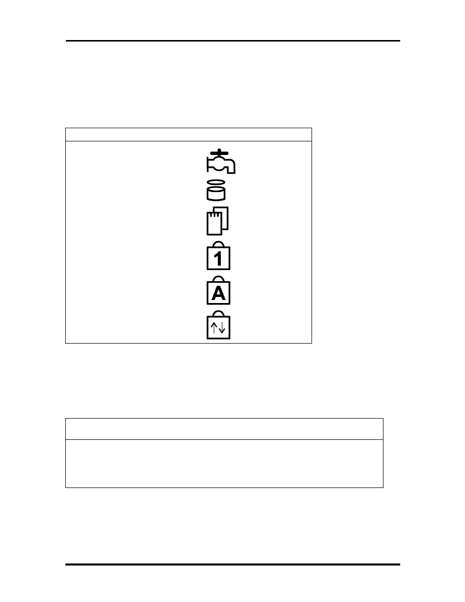
General Specifications 2-13
LED STATUS INDICATORS
The following table lists NEC Versa 2400 Series LEDs. For example, the AC IN LED lights
to indicate power is on and that the battery is charging.
Table 2-9 Status LED Descriptions
ITEM
LED
PMU Enabled
HDD Read / Write
PCMCIA Slots
Num Lock
Caps Lock
Scroll Lock
FDD SPECIFICATION
The following table lists the standard diskette drive specifications.
Table 2-10 FDD Specifications
ITEM
Specification
Module
3.5” Module
Mode
2 Mode FDD (1.44MB / 720KB)
Unit Size
110mm (L) x 96mm (W) x 12.7mm (H)
SOLD BY laptopia2005 DO NOT RESELL!!
SOLD BY laptopia2005 DO NOT RESELL!!
2-14 General Specifications
HDD UNIT SPECIFICATION
The following table lists the standard hard drive specifications.
Table 2-11 Hard Disk Drive Specifications
ITEM
SPECIFICATION
Module
2.5” Removable HDD Module
Capacity
810MB / 1 GB
Interface
Enhanced IDE Interface
Unit Size
100mm (L) x 70mm (W) x 12.7mm (H)
CD-ROM SPECIFICATION
The following table lists the standard CD-ROM reader specifications.
Table 2-12 CD-ROM Reader Specifications
ITEM
SPECIFICATION
Module
6X CD-ROM
Mode
IDE Interface
Data Transfer
13.3MB/sec
Unit Size
140.5mm (L) X 130.6mm (W) X 17.0mm (H)
NIMH BATTERY PACK SPECIFICATION
The following table lists the standard battery specifications.
Table 2-13 Battery Specifications
ITEM
SPECIFICATIONS
Capacity
3500 mA x 10 cells
Cell Type
Long A
Voltage
12V
Connector
10-Pin
SOLD BY laptopia2005 DO NOT RESELL!!
SOLD BY laptopia2005 DO NOT RESELL!!

General Specifications 2-15
DC/DC CONVERTER & BATTERY CHARGER SPECIFICATION
The following table lists DC/DC converter & battery charger specifications.
Table 2-14 DC/DC Converter & Battery Charger
ITEM
SPECIFICATION
Input Voltage
9V -> 20V
Output Voltage
12V, 5V, 3.3V
Output Current
0.1A, 2.5A, 2.5A
Output Ripple
Voltage
150mV, 100mV, 100mV
Protection
Short Circuit Protection, OCP
Input under voltage latch
Efficiency
80% Min. (Typ.)
PCB
1.2mm / 6 Layers
BATTERY CHARGER
The following table lists battery charger specifications.
Table 2-15 Battery Charger Specifications
ITEM
SPECIFICATION
Input Voltage
20V (Max.)
Support Battery
NiMH Battery (12V)
Protection
Max. Temp., Max. Timer
Charge Method
Delta T / Delta t: 1
o
C (min.)
Max. Temperature
53
o
C ~ 60
o
C
Timer Setting
360 Min.
Charge Time
Machine On: 6 hours
Machine Off: 1.5 hours
Charge IC
BQ2014
Connector
To M/B:
10 Pin & 18 Pin, Male, Straight, DIP/SMT
SOLD BY laptopia2005 DO NOT RESELL!!
SOLD BY laptopia2005 DO NOT RESELL!!
2-16 General Specifications
KEYBOARD
The following table lists keybord specifications.
Table 2-16 Keybord Specifications
ITEM
SPECIFICATION
Key Switch Type
Membrane
Key Stroke
3.0
±
0.5mm
Operating Force
50
±
20GF
Key Pitch
19.05mm
AC/DC ADAPTER
The following table lists AC/DC adapter specifications.
Table 2-17 AC/DC Adapter Specifications
ITEM
SPECIFICATION
Input Voltage
AC 90V -> 265V, 50 -> 63Hz
Ripple Noise
100mvp-P
Output Voltage
20V Max.
Protection
Short Circuit UVP, OVP
AC Cord
Safety Approval, FCC Shielding AC cord
DC Output Cable
2-pin, 100cm long with coil at system end
Indicator
AC Power On
Unit Size
120mm (L) x 62mm (W) x 36mm (H)
SOLD BY laptopia2005 DO NOT RESELL!!
SOLD BY laptopia2005 DO NOT RESELL!!

General Specifications 2-17
BIOS
The following table lists BIOS specifications.
Table 2-18 BIOS Specifications
ITEM
Specification
Floppy Disk Drive
Support standard 3.5” FDD
Support 720KB and 1.44MB Modes
Hard Disk Drive
Support Standard IDE Hard Disk
Auto-detect IDE Features
Support LBA mode for larger capacity
VGA Display
Use Chips OC65548 VGA BIOS to support Monitor Sense or Auto
Display
PCI Super VGA Function Call
8 Sets Built-In Panel Parameters
Serial Port
Support Standard COM Port Address with optional selection on
Setup Menu
Support for IR communication port
Parallel Port
Support EPP, ECP, and Standard Printer Port Address
Provide Optional Item in Parallel Port on Setup Menu
Shadow & Cache
Always enable VGA and System BIOS Shadow
PCMCIA
Phoenix PCM Plus will be provided
PCMCIA 2.1 Spec Compliance
External Device
Support
Interface of external PS/2 mouse and external keyboard
The internal Glide Pad will be disabled while external PS/2 mouse
is connected
CD-ROM
Can save power during Suspend Mode
APM
Supports APM 1.1 Specification
Power Management
Support
Full On Mode
Doze Mode
Standby Mode
Suspend Mode (Suspend to RAM)
Save to Disk
System Off Mode
VGA Display
Boot on simultaneous display while external monitor attached
SOLD BY laptopia2005 DO NOT RESELL!!
SOLD BY laptopia2005 DO NOT RESELL!!
2-18 General Specifications
Table 2-18 BIOS Specifications
ITEM
Specification
Suspend (To RAM)
STR can be invoked by Hot-Key, Cover-Switch, Battery Low-Low
Condition, & Operating System request
STR can be resumed by Keyboard && Power Button
Save To Disk
STD can be invoked by Hot-Key, Cover-Switch, Battery Low-Low
condition & Operating System request
STD can be resumed by Power Button only.
MICRO-CONTROLLER FUNCTION DESCRIPTION
The following table lists Micro-Controller specifications.
Table 2-19 Micro-Controller Specifications
ITEM
SPECIFICATION
Keyboard Type
US Keyboard: 87 Keys
European Keyboard: 88 Keys
Support WIN95 extra 3 Keys
External Device
Support
Internal and External Keyboard can be used simultaneously.
Internal Glide Pad and External PS/2 Mouse can be used
Simultaneously
Y-Connector Support
External PS/2 Mouse and External Keyboard can be used
LED Connector
Num Lock, Caps Lock & Scroll Lock Status should be kept during
Suspend Process.
All the above should be cleared while Power On
Support AC-IN, Battery-Charging, Battery-Low, Suspend-To-RAM
Status LED
System Peripheral
Control
Support the Audio/Contrast/Brightness control
Support the Backlight control
SMI Signal
Edge Trigger (High Active)
Activity Events
Hot-Key Press
Battery Low & Battery Low-Low
Cover Switch =>
Enter into Suspend Mode or Turn off Backlight via CMOS SETUP
SOLD BY laptopia2005 DO NOT RESELL!!
SOLD BY laptopia2005 DO NOT RESELL!!

General Specifications 2-19
POWER MANAGEMENT FEATURES (MODE DEFINITION)
The following table lists power management specifications.
Table 2-20 Power Management Modes
Mode
Device
Speed
Full-On Mode
CPU State
Peripherals State
Full speed
Normal
Doze Mode
Timer
CPU State
DRAM State
Peripherals State
Activity Events
On / Off
Stop Grant State
Slow Refresh
Normal
Video Monitoring, Keystrokes,
FDD, HDD, Com1, Com2, Lpt2,
Audio
Standby Mode
Timer
CPU State
DRAM State
VGA State
Audio State
AMP Circuit
HDD State
LCD state
Activity Events
Off/1/2/4/8/16 Min.
Stop Clock
Slow Refresh
Standby
Power Down
Power Down
Power Down
Backlight Off, Negative Volt.
Off
Video Monitoring, Keystrokes,
FDD, HDD, Com1,Com2, Lpt1,
Audio
Suspend To RAM
Timer
CPU State
DRAM State
LCD State
VGA, HDD, I/O Chip, PCMCIA,
Audio, AMP Circuit, KBC, Clock
Generator
Power-On Group
Activity Events
Off/1/2/4/8/16 Min
Stop Clock
Slow Refresh
Backlight off, Negative Volt. Off
Power Down
UM8890BN
Keyboard, Power, Com1,
Fax/Modem, PCMCIA Ring
SOLD BY laptopia2005 DO NOT RESELL!!
SOLD BY laptopia2005 DO NOT RESELL!!
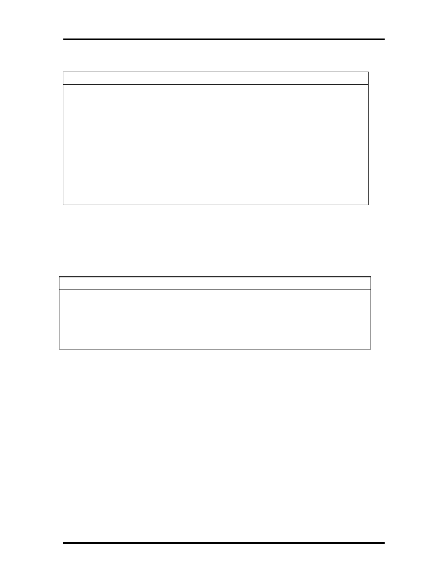
2-20 General Specifications
Table 2-20 Power Management Modes
Mode
Device
Speed
Suspend To Disk
Timer
CPU State
Power System
Power-On Group
Activity Events
Off/1/2/4/8/16 Min
Off
Off
Micro-Controller
Power Switch
Battery Low
Condition
CPU State
LCD State
CPU Clock/2
Backlight On (Lower 25%)
Battery Low / Low
Condition
CPU State
System Power
Off
Off
POWER MANAGEMENT FEATURES (MODE TRANSITION)
The following table lists power management transition modes.
Table 2-21 Mode Definitions
FROM/TO
FULLY-ON
DOZE
SLEEP
SUSPEND
Fully-On
X
1
X
2
Doze
3
X
4
5
Sleep
6
X
X
7
Suspend
8
X
X
X
O current Condition:
1.
Doze Mode Time-Out
2.
APM CPU-Idle
3.
APM Power Management Event: System Suspend Request Notification
4.
Battery Low - Low Condition
5.
Suspend Events Occurs
6.
Fully-On Activity Events Occur
7.
Sleep Mode Time-Out
8.
Sleep Timer Disabled and Suspend Mode Time-Out
9.
Battery Low - Low Condition
SOLD BY laptopia2005 DO NOT RESELL!!
SOLD BY laptopia2005 DO NOT RESELL!!
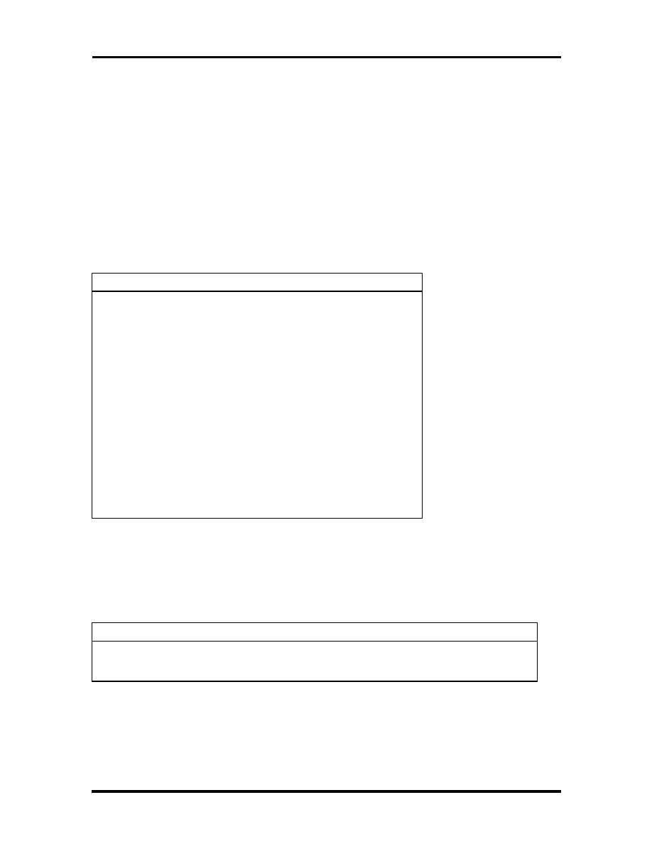
General Specifications 2-21
10.
Fully-On Activity Events Occur
11.
Suspend Mode Time-Out
12.
Battery Low - Low Condition
13.
Resume Events Occur
HOT KEY DEFINITION
The following table lists hot key definitions.
Table 2-22 Hot Keys
FUNCTION KEY
CONTENT
<Fn> + <Esc>
Suspend
<Fn> + <F10>
LCD/CRT/SIMUL. Display
<Fn> + <F11>
Panel Backlight On/Off
<Fn> + <F8>
Sound Mute
<Fn> + <right>
Contrast Up
<Fn> + <left>
Contrast Down
<Fn> + <PgUp>
Speaker Volume Increases
<Fn> + <PgDn>
Speaker Volume Decreases
<Fn> + <up>
Brightness Increases
<Fn> + <down>
Brightness Decreases
<Num>
Numeric Lock
ENVIRONMENTAL SPECIFICATION
The following table lists appropriate operating temperatures.
Table 2-23 Environmental Specifications
ITEM
SPECIFICATION
Operating Mode
∗
5
o
C ~ 35
o
C (80%)
Non-Operating
∗
-20
o
C ~ 60
o
C (90%)
SOLD BY laptopia2005 DO NOT RESELL!!
SOLD BY laptopia2005 DO NOT RESELL!!
2-22 General Specifications
POWER SOURCE
The following table lists system power specifications.
Table 2-24 Power Specifications
Input
Nominal
Version
AC Voltage
100 ~ 250 V
90 ~ 265 V
AC Frequency
50 / 60 Hz
47 ~ 63 Hz
VIBRATION
The following table lists vibration specifications.
Table 2-25 Vibration Specifications
ITEM
MODE
Operating Mode
Direction of Movement: X, Y, Z Axis
Vibration Level: 5 ~ 500 ~ 5 Hz, 0.5 Gs Acceleration
Duration Time: 60 min. for each axis
Non-Operating
Direction of Movement: X, Y, Z Axis
Vibration Level: 5 ~ 500 ~ 5 Hz 2 Gs Acceleration
Duration Time: 60 min. for each axis
SOLD BY laptopia2005 DO NOT RESELL!!
SOLD BY laptopia2005 DO NOT RESELL!!
General Specifications 2-23
SHOCK
The following table lists system shock specifications.
Table 2-26 Shock Specifications
ITEM
MODE
Operating Mode
Impact Accelerator: 1g/10g Based on Half Sine-Wave Shock
Pulses of 11Msec
Number of Shock: 3 Shocks for each of the 6 faces
Direction of movement: 6 Faces
Non-Operating Mode
Impact Accelerator: 10g, 20g, 30g, 40g, 50g Based on Half Sine-
Wave Shock Pulses of 11Msec
Number of Shock: 3 Shocks for each of the 6 faces
Direction of Movement: 6 Faces
ELECTRO-STATIC DISCHARGE (ESD)
The following table lists static discharge specifications.
Table 2-27 Electro-static Discharge Specifications
ITEM
SPECIFICATION
Contact Discharge
±
2, 4, 8, 12.5, 15 kV
Air Discharge
±
2, 4, 15 kV
HCP
±
2, 4 kV
VCP
±
2, 4 kV
SOLD BY laptopia2005 DO NOT RESELL!!
SOLD BY laptopia2005 DO NOT RESELL!!

Section 3
Hardware Functional Overview
The NEC Versa 2400 Series notebooks consist of several major functions and subsystems
including:
system BIOS - implemented on the system board and EPROM
system processor - implemented on the system board
system logic controller - implemented on the I/O Board
memory subsystem - implemented on the system board
video subsystem - implemented on the I/O board, LED board, and LCD display
panel
I/O subsystem - implemented on the I/O board
keyboard subsystem - implemented on part of the system board, and keyboard as-
sembly
PCMCIA controller and sockets - implemented on the system board
pointing device subsystem - implemented on the I/O board and keyboard assembly
hard disk subsystem - implemented on the system board and the hard drive as-
sembly
floppy disk subsystem - implemented on the system board and the floppy drive
power subsystem - implemented on the power supply board, inverter board, bat-
tery packs, and AC adapter
A simplified block diagram of the notebook is shown on the next page.
SOLD BY laptopia2005 DO NOT RESELL!!
SOLD BY laptopia2005 DO NOT RESELL!!
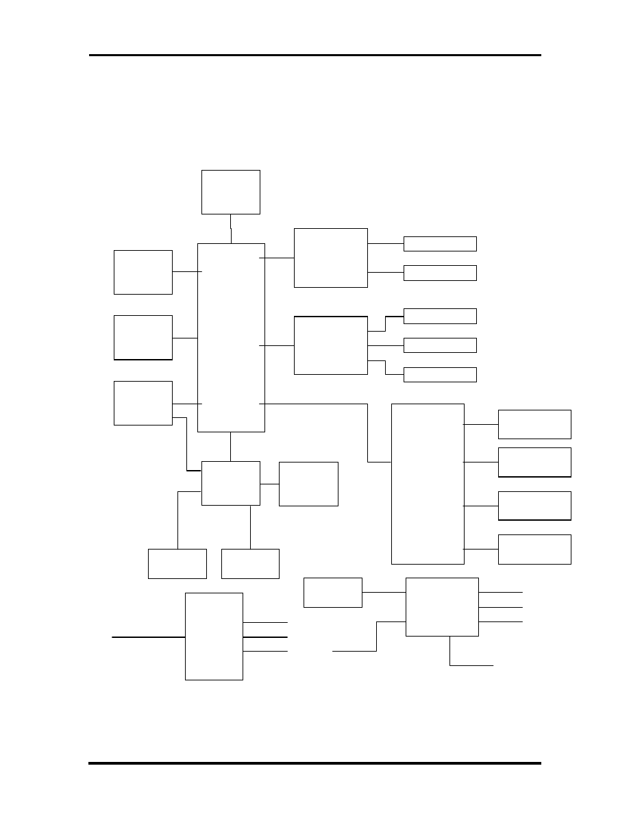
3-2 Hardware Functional Overview
FUNCTIONAL BLOCK DIAGRAM
The following figure shows the NEC Versa 2400 Series functional diagram.
Bank 0
8 M B
(on-board)
Bank 1
8, 16MB
(DIMM)
Pentium
P 5 4 C S L M -
1 0 0 M H z
C O R E C H I P
U M C
U M 8 8 9 1 B F - N ,
U M 8 8 9 2 B F - N ,
U M 8 8 8 6 B F - N
V G A C H I P
C & T 6 5 5 4 8
C R T O N
L C M
I N V E R T E R
F L A S H B I O S
2 5 6 K B
P C M C I A
O M E G A
8 2 C 0 9 4
K B
C O N T R O L L E R
MITSUBISHI
M 3 8 8 1 3 M 4
S U P E R I / O
N S P C 8 7 3 3 6 V L J
G L I D E P A D
E X T . K B / M O U S E
I N T E R N A L K B
C A R D 1
C A R D 0
F D D
H D D
P R I N T E R
C L O C K G E N
ICS
A V 9 1 5 4 - 4 3
A C
A D A P T E R
D C / D C
C O N V E R T E R
1 4 . 3 1 8 M H z
2 4 M H z
6 6 M H z
14.318MHz X'TAL
BATTERY IN
+ 3 . 4 5 V
+ 5 V
+ 1 2 V
D C - I N
V I D E O R A M
1 M B
C O M 1
Figure 3-1 Functional Block Diagram
SOLD BY laptopia2005 DO NOT RESELL!!
SOLD BY laptopia2005 DO NOT RESELL!!

Hardware Functional Overview 3-3
SYSTEM BIOS
In AT-compatible systems, configuration data must be stored somewhere when the com-
puter is turned off. This data is usually stored in the CMOS RAM. Unlike the DRAM, used
for system memory, the CMOS RAM requires very little power. When the computer is
turned off, a back-up battery powers the CMOS RAM, which retains the system parame-
ters. The computer is configured with the values stored in the CMOS RAM by the system
BIOS, which gains control when the computer is powered on.
The primary function of the system BIOS (Basic Input-Output System) is to provide a se-
ries of software interrupts, functions, and sub-functions that control operations on certain
devices, such as the hard disk drive, the floppy drive, and the video subsystem.
The NEC Versa 2400 Series uses the Phoenix BIOS. The BIOS SETUP program is an
easy-to-use system utility configuration that sets system parameters and copies them on the
EPROM chip with the system BIOS.
The EPROM chip also includes BIOS Power-On Self Test (POST) diagnostic and booting
codes that tests the system components, initializes certain data structures, and boots the op-
erating system.
System Processor
The system processor function for the notebook is implemented on the system board using
an Intel P54LM-100MHz Processor Chip. The processor operates in conjunction with the
RAM and ROM memory plus other system control logic (e.g. UMC 8486F) to process
software instructions (BIOS, Windows, applications).
The Intel P54CSLM microprocessor is a high performance 586-class CPU which is com-
patible with all the popular x86 operating systems including DOS, Windows, Windows NT,
Windows 95, Unix, Novell, and OS/2. The super pipelined architecture of the integer unit
combined with single cycle execution, branch prediction, 16-Kbyte write-back cache, and
single cycle instruction decode results in true 586-class performance. These features result
in a 60 to 90 percent gain in processing speed compared to the Cyrix 486DX2-50.
Additionally, the P54CSLM CPU provides many power savings features making it ideal for
power sensitive systems like notebook computers. Aside from operating at 3.45V only, the
CPU clock can also be completely stopped. Moreover, the CPU automatically powers down
the FPU and other internal circuits when not in use. Fast entry and exit from the SMM
mode allows frequent use of the SMM feature without noticeable performance degradation.
Major Functional Blocks
The Intel P54CSLM, in a 320-pin TCP packaging, is divided into five major functional
blocks:
Integer Unit
Floating Point Unit
SOLD BY laptopia2005 DO NOT RESELL!!
SOLD BY laptopia2005 DO NOT RESELL!!

3-4 Hardware Functional Overview
Cache Unit
Memory Management Unit
Bus Interface Unit
Instructions are executed in the Integer Unit pipeline and in the Floating Point Unit (FPU).
The Cache Unit stores the most recently used data and instructions and provides fast access
to this information for the Integer and Floating Point Units.
When external memory access is required, the physical address is calculated by the Memory
Management Unit and then passed to the Bus Interface Unit (BIU). The BIU provides the
interface between the external system board and the processor’s internal execution and
cache units.
SYSTEM LOGIC CONTROLLER
The System Logic Controller function for the notebook is implemented on the system board
using UMC 8890 Series Notebook Chipset. The UM8890 is an advanced 586 compatible
single chip specially designed for notebook computers and other portable computers. Aside
from supporting almost all 586-based CPUs, the UM8890 also integrates PMU, System
Controller, RTC and Peripheral Controller (206) into a single 208 QFP package.
Features Summary:
System -
Fully compatible with IBM PC/AT
Supports PCI Bus-Master mode
System Operation Voltage from 3V to 5.5V
Three programmable non cacheable regions
Flash ROM Boot block erase protection
Supports general purpose I/O
Hybrid Voltage
208 Pins QFP
Integration -
Built-in 206
Built-in 146818A
Built-in Memory Controller
SOLD BY laptopia2005 DO NOT RESELL!!
SOLD BY laptopia2005 DO NOT RESELL!!

Hardware Functional Overview 3-5
Memory Controller -
Supports ROM DOS up to 64MB by XIP, 16MB by EMS
Supports Shadow RAM from C0000-FFFFF
Supports SLOW and SELF Refresh DRAM
Supports Stagger Refresh
On-board memory up to 48MB
Supports Three Memory Banks
Supports Page Mode/Burst mode operation
Supports 512KBx8, 1Mx4, 1Mx16, 2Mx8 and 4Mx4 type DRAM
Supports 8 or 16 bit ROM configuration
Programmable DRAM timing for each bank
Power Management -
Supports up to Ten Programmable PMC Outputs
Supports Multiple Power Saving Mode
All Register Read/Writeable for 0V SUSPEND
Microsoft APM Compatible
Supports 0V SUSPEND
Demand Driven Clock Control
Supports RESUME/SUSPEND Key
Auto-Wake Up Function
Three Low Battery Monitor Input
System Operating Voltage from 3V to 5.5V
Low Power Consumption (at 3.3V)
SOLD BY laptopia2005 DO NOT RESELL!!
SOLD BY laptopia2005 DO NOT RESELL!!

3-6 Hardware Functional Overview
MEMORY SUBSYSTEM
The memory subsystem, implemented on the system board, includes ROM and DRAM
memory. Primary control for the memory subsystem is provided by the UMC 8890 System
Controller chipset.
DRAM Memory
The NEC Versa 240X notebooks contain 8MB (16MB for NEC Versa 243X) of 70ns
page-interleaved DRAM on the System board. The notebook provides one extra memory
slot for upgrading the DRAM memory to 8MB, 16MB, 24MB, 32MB, 40MB, & 48MB for
the NEC Versa 2400 Series) using standard JEDEC small-outline DIMM memory modules.
(Refer to Chapter 1 on System Upgrades to know more about how to upgrade the system
memory).
ROM Memory
The NEC Versa 2400 Series notebooks contains both the main system BIOS and the VGA
BIOS with Shadow BIOS capability.
I/O SUBSYSTEM
The I/O Subsystem of the notebook is implemented on the I/O Board using the NS
PC87336VLJ chipset. The supported I/O interface on the notebook includes the internal
hard disk drive interface, the internal floppy disk drive interface, the external printer port
interface, the external serial port, and the external PS/2 keyboard and mouse ports.
Feature’s summary of the NC87336VLJ:
Compatible with IBM AT architecture
Supports up to two 360K, 720K, 1.2M, or 1.44MB floppy disk drives
Supports IBM PC/AT interface to IDE (Intelligent Drive Electronics)-type Win-
chester drives
Hardware or software configuration
Address decoding and strobe generator for game port
Supports two serial port functions
Supports one bi-directional IBM PS/2 compatible parallel port function
All functions can be enabled or disabled individually
Configuration Register can be easily selected
Only one 24MHz crystal needed
100-pin plastic flat package
SOLD BY laptopia2005 DO NOT RESELL!!
SOLD BY laptopia2005 DO NOT RESELL!!

Hardware Functional Overview 3-7
VIDEO SUBSYSTEM
The video subsystem, implemented on the system board and on the LCD Panel, controls the
display output to both the LED Panel and to the external VGA port.
The video subsystem utilizes the C&T 65548 High Performance Flat Panel / CRT VGA
Controller. It also includes 1MB DRAM memory, 32-bit DRAM bus, and separate display
and memory clocks. An additional frame buffer/accelerator DRAM increases the available
memory bandwidth for CPU accesses.
Video Chipset Controller
The C&T 65548 initiates a family of 208-pin, high performance for the full-featured note-
book that requires the highest graphics performance available. The 65548 achieves superior
performance through direct connection to system processor buses up to 32-bits in width.
When combined with the CHIPS’ advanced linear acceleration software driver technology,
this device exhibits exceptional performance compared with devices of similar architecture.
The 65548 also adds a sophisticated 32-bit graphics hardware engine for the Bit Block
Transfer (BITBLT), line drawing, hardware cursor, and other functions intensively used in
Graphical User Interface (GUIs) such as Microsoft Windows.
Features Summary:
Highly integrated design (flat panel/CRT VGA controller, RAMDAC, clock syn-
thesizer)
Multiple Bus Architecture Integrated Interface
Local Bus (32-bit CPU Direct and VL)
EISA/ISA (PC/AT) Bus
PCI Bus
Flexible display memory configurations
Two 256Kx16 DRAMs (1MB)
Integrated programmable linear address feature accelerates GUI performance
Hardware windows acceleration (65548)
32-bit graphics engine
System-to-screen and screen-to-screen BitBlt
3 operand ROP’s
Color expansion
Optimized for Windows BitBlt format
SOLD BY laptopia2005 DO NOT RESELL!!
SOLD BY laptopia2005 DO NOT RESELL!!

3-8 Hardware Functional Overview
Hardware line drawing
64x64x2 hardware cursor
High performance resulting from zero wait-state writes (write buffer) and mini-
mum wait-state reads (internal asynchronous FIFO design)
Supports panel resolutions up to 800x600
Supports non-interlaced CRT monitors with resolutions up to 1024x768 at 256
colors
True-color and Hi-color display capability with flat panels and CRT monitors up
to 800x600 resolution
Advanced power management features minimize power consumption during:
Normal operation
Standby (Sleep) modes
Panel-Off Power-Saving Mode
Power Sequencing control outputs regulate application of Bias voltage, +5V to
the panel and +12V to the inverter for backlight operation
Fully compatible with IBM VGA
EIAJ-standard 208-pin plastic flat pack
External VGA Capability
The NEC Versa 2400 Series notebooks provide a 15-pin female D-type external VGA con-
nector that can be connected to an external video graphics adapter (VGA) type monitor.
Another feature of the notebook computer is the ability to auto-sense the display output to
both LCD and the external CRT monitor. The notebook provides external resolution of
1024x768 by 256 colors for the NEC Versa 2400 series with 1MB video memory. The
NEC Versa 2400 Series can also provide simultaneous display at 800x600 at 256 colors
with the standard VGA DSTN LCD.
KEYBOARD SUBSYSTEM
The Keyboard Subsystem of the notebook is implemented on the I/O Board and Keyboard
Assembly using the Motorola G10 LapKat keyboard controller chip.
The NEC Versa 2400 Series keyboard is an 87/88-key, IBM enhanced-type keyboard with
standard characters and function keys plus 12 programmable function keys and the Special
Function (Fn) key. The notebook also provides an external PS/2 port for supporting an ex-
ternal PS/2 keyboard or standard DIN-type AT-keyboard. See Section 1 for more informa-
tion.
SOLD BY laptopia2005 DO NOT RESELL!!
SOLD BY laptopia2005 DO NOT RESELL!!

Hardware Functional Overview 3-9
PCMCIA CONTROLLER AND SOCKETS
The PCMCIA controller is implemented on the system board using Omega’s 82C094 Inter-
face Controller. The 82C094 is compatible with the Intel i882092AA PCI to PCMCIA
controller chip. It supports two independent 68 pins PC card sockets and is register com-
patible with Intel’s 82365SL.
The NEC Versa 2400 Series notebook incorporates PCMCIA double deck slots that sup-
ports insertion of two Type I or II cards at the same time or one Type III card on the upper
slot and one Type I or II card on the bottom slot.
Feature summary of the Omega 82C094:
PC Card 95, PCMCIA 2.1, and JEIDA 4.1 compatible Interface
Power Management Function that includes Individual Socket power control, Hot
insertion/removal, Hardware/Software controlled power down, Modem Ring in
Resume, CS Controlled Power Down, and Power Saving with Windows inactivity
Direct connection to 33MHz PCI bus and to PCMCIA sockets without glue logic
Serial Power Control to support the designs with most PCMCIA power switch IC
Legacy DMA and serial IRQ to directly support advanced PCI Core Logic
Single-Chip PCMCIA host controller
Supports CLOCKRUN# of the PCI Mobile Design Guide for power saving
Intelligent power management for lowest operating power
Programmable power management with individual socket activity counter
Four-level FIFO and programmable PCMCIA interface timing
Five programmable memory windows and two programmable I/O windows per
socket
Intel EXCA register compatible
Register-set compatible to Intel i82092AA (PPEC) and Intel i82365SL
208 Pin PQFP or TQFP
SOLD BY laptopia2005 DO NOT RESELL!!
SOLD BY laptopia2005 DO NOT RESELL!!

3-10 Hardware Functional Overview
HARD DISK SUBSYSTEM
The hard disk subsystem, implemented on the system board and on the associated built-in
hard disk drive, provides disk storage for all system software and user files.
The NEC Versa 2400 Series notebook is equipped with high capacity hard disk drive rang-
ing from 810MB to 1.4GB using the IDE controller with LBA (Logical Block Addressing)
mode support. The I/O subsystem controller, NS PC87336CLJ, provides the IDE controller
for the hard disk.
The built-in hard drive can support any industry standard 2.5-inch IDE hard disk drive at
19mm or 17mm height. Setting up the hard disk type is done automatically by the CMOS
SETUP programs that auto-detects the installed hard disk type settings for optimized per-
formance.
NOTE: Do not move the notebook when the
HDD LED is activated. This protects the hard
disk drive from any accidental damage or loss of
data.
FLOPPY DISK DRIVE SUBSYSTEM
The Floppy Disk Drive Subsystem consists of a FDD controller provided by SMC
37C665IR and the built-in floppy disk drive. The floppy disk drive supports standard
3.5-inch 720KB and 1.44MB mini-diskettes.
POINTING DEVICE SUBSYSTEM
The pointing device subsystem consists of the VersaGlide device on the system top cover
assembly and a pre-programmed Mitsubishi M38813M4 micro-controller that interfaces the
mouse device to the Motherboard. An external PS/2 port also supports the use of an exter-
nal PS/2 compatible mouse which the system automatically detects during system power up
and then disables the internal VersaGlide.
POWER SUBSYSTEM
The Power Subsystem consists of the following major sections:
External AC Power Adapter
Internal Battery Pack
Powerboard (on Motherboard)
LCD Inverter Board (in LCD Panel Assembly)
Power Conservation Logic (part of Motherboard)
SOLD BY laptopia2005 DO NOT RESELL!!
SOLD BY laptopia2005 DO NOT RESELL!!

Hardware Functional Overview 3-11
AC Power Adapter
The computer is equipped with a universal AC power adapter that converts AC voltage (90
to 265VAC, 47 to 63Hz) into DC voltage used to operate the notebook and charge the
batteries.
Internal Battery Pack
The NEC Versa 2400 Series notebooks utilizes NiMH (Nickel Metal-Hydride) that pro-
vides DC power for the notebook (and for the NVRAM and real time clock battery on the
Motherboard) when the AC Adapter is not connected to the computer.
The battery pack contains ten size A battery cells that provide the system with 12V. When
installed in the notebook, the battery LED automatically appears and will also start to re-
charge whenever the AC adapter is connected to the notebook.
Normal charging time for the battery pack is around 1.5 hours when the computer is turned
off while it should take around 6 hours maximum when the computer is running.
Power Board
The power board receives approximately 12VDC from the battery pack and uses this input
voltage to generate +12V, +5V, +3.3V, (+3.45V) regulated output voltages to provide
power for all internal notebook board assemblies. The output of the +5V regulator also
drives the LCD inverter circuit on the LCD inverter board assembly. Refer to Chapter 2 for
more detailed information.
LCD Inverter Board Assembly
The LCD Inverter Board Assembly, located in the LCD Panel Assembly, converts the
+5VDC input from the Powerboard module of the system board into a high voltage AC
output used to light the CCFT (Cold-Cathode Fluorescent Tube).
SOLD BY laptopia2005 DO NOT RESELL!!
SOLD BY laptopia2005 DO NOT RESELL!!

Section 4
Field Service Guidelines
This section contains preventive and corrective maintenance procedures for the NEC Versa
2400 Series notebook computers. The first part of this section will describe the computer
cleaning procedures and preferred handling procedures for sensitive components (i.e. disk
drives, batteries).
The second part of this section will identify all field replaceable parts plus the removal and
replacement procedures for these parts.
PREVENTIVE MAINTENANCE
Preventive maintenance is limited to cleaning the plastic case, the keyboard, the display
screen, and the floppy drive heads as required.
NOTE: Remove the battery and disconnect the
AC adapter before performing any maintenance.
Voltage will still be present inside the system unit
and LCD even after the system has been turned
off.
Cleaning the Notebook’s Exterior
Use the steps described below to clean the outer surface of the system.
1.
Power off the system, remove the primary battery pack, and unplug all cables
connected to the system.
2.
Wipe the outside of the system unit, keyboard, and display with a soft, clean cloth.
Remove any stains with water only. Use glass cleaner to clean the LCD indicator
panel. Apply the glass cleaner directly to the cloth and then wipe the LCD indica-
tor panel. Do not use solvents or strong, abrasive cleaners on any part of the sys-
tem.
3.
Clean the keys with a damp cloth. A small, soft-bristle brush may be used to clean
between the keys. Make sure to use a damp cloth (not wet) to prevent moisture
from seeping between the keyboard and the metal plate, this could possibly dam-
age the components under the keys. If the keyboard gets wet, thoroughly dry it
before reassembling the system unit.
SOLD BY laptopia2005 DO NOT RESELL!!
SOLD BY laptopia2005 DO NOT RESELL!!

4-2 Field Service Guidelines
Cleaning the Notebook’s Interior
When servicing the inside of the notebook to remove dust and other foreign particles pro-
ceed as follows:
1.
Remove the top cover, hinge covers, status bar, and keyboard using the disas-
sembly procedures discussed later.
2.
Dust or vacuum (with a rubber-tipped nozzle) the inside of the system unit, par-
ticularly the system board surface. Use care to avoid damaging or dislodging any
components or cables.
3.
Inspect all cable connectors for damage. Ensure that all connectors are seated
properly before replacing the cover.
Protecting the Disk Drives
To protect the disk drives and data, we recommend that you back up the system disk peri-
odically on floppy diskettes. Occasionally use a head-cleaning diskette in the floppy disk
drive to prolong the life of the drive and to help maintain data integrity.
Here are some preventive maintenance tips that we recommend you use when handling the
hard disk:
Periodically back up the data files from the hard disk.
Run a virus detection program to identify possible viruses on the hard disk.
Use SCANDISK to correct any errors found in the directory and File Allocation
Table (FAT). This will also free up space from any unused sectors.
Never turn the computer off when the hard disk is being accessed.
Never move or raise the computer while the hard disk is being accessed, impor-
tantly don't jar the hard disk, as this may cause a hard disk crash.
Use hard disk maintenance programs like DEFRAG under DOS or Norton Utili-
ties SPEEDISK to reorganize your hard disk by eliminating fragmentation and
improving hard disk access time.
Handling the Computer Battery Packs
The battery packs furnished with the computer require reasonable care and handling to en-
sure efficient operation and maximum life. Periodically inspect the battery terminals and the
batteries for evidence of corrosion and/or oxide build-up.
To ensure that the battery packs endure a normal life cycle, always observe the following
precautions when handling the battery packs:
Do not drop the battery packs or subject them to excessive shock and vibration.
SOLD BY laptopia2005 DO NOT RESELL!!
SOLD BY laptopia2005 DO NOT RESELL!!

Field Service Guidelines 4-3
Do not expose the battery packs to direct sunlight, moisture, or chemical com-
pounds.
Do not disassemble the battery packs.
Do not use the battery packs to power other devices.
Do not short the battery leads or connect the battery with reversed polarity.
Never attempt to charge the battery packs in any way other than as described in
this manual and the user’s guide.
Always charge the battery packs as soon as possible after a low battery indication.
Maintaining the LCD Quality
Heat is the most common problem associated with the screen. After a lengthy work session,
the typical routine is to shut down the machine and close the cover, but the display surface
(no matter what type it is) and the components inside the computer radiate heat. So, when
you close the cover, you will then trap this heat up against the screen. Leaving the computer
cover open for about ten minutes while the heat disperses will eliminate this potentiality
damaging situation.
REQUIRED TOOLS AND EQUIPMENT
All NEC Versa 2400 corrective maintenance procedures can be performed using the follow-
ing tools:
tweezers
small flat-blade screwdriver
small Phillips screwdriver
small Hex-bolt screwdriver.
NOTE: All boards, options and peripherals
contain components that are sensitive to static
electricity. When handling any of these items,
protect against static discharge by using wrist or
ankle grounding straps and grounded working
mats. When moving or storing items, use the
anti-static bags supplied with the items.
SOLD BY laptopia2005 DO NOT RESELL!!
SOLD BY laptopia2005 DO NOT RESELL!!

4-4 Field Service Guidelines
PARTS REMOVAL AND REPLACEMENT PROCEDURES
This section contains field service-level removal/replacement procedures for the notebook.
Refer to the exploded diagram later in this section to identify all relevant parts. The NEC
Versa notebook is designed for optimum modularity in order to make field replacement
maintenance easy and efficient.
Removing/Replacing the Notebook Battery Pack
The procedure for removing and replacing the battery pack is as follows:
1.
Turn off the computer. Close the LCD cover and turn the whole unit over.
2.
You will find a clamp latch (lock knob) that is securing the internal battery pack
to the system unit. To remove the battery pack, push the lock knob sideways with
one hand and with the other hand pull the battery pack out. Note that this has to
be done simultaneously.
3.
To replace the battery pack again, simply slide the battery pack into the system
unit until you hear the spring latch hook snap into place. The battery pack can
only be inserted in one direction so there is no danger of improper insertion.
SOLD BY laptopia2005 DO NOT RESELL!!
SOLD BY laptopia2005 DO NOT RESELL!!
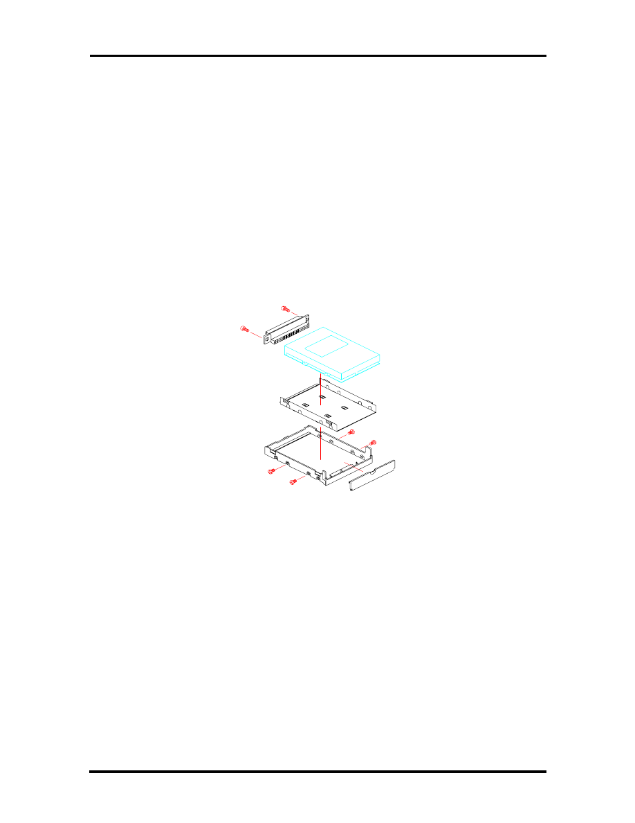
Field Service Guidelines 4-5
Removing/Replacing the Hard Disk Drive Module
The procedure for removing and replacing the hard disk drive module is as follows:
1.
Turn off the computer. Close the LCD cover and turn the whole unit over.
2.
You will find a clamp latch (lock knob) that is securing the hard disk drive module
to the system unit. To remove the hard disk drive module, push the lock knob
sideways with one hand and with the other hand pull the hard disk drive module
out. Note that this has to be done simultaneously.
3.
To replace the hard disk drive, remove the four flat screws attaching it to the null
hard disk assembly and remove the hard disk drive cable.
4.
To replace the hard disk drive module, reverse the above procedure.
Figure 4-1 Hard Drive Module Assembly
Removing/Replacing the Floppy Disk Drive Module
The procedure for removing and replacing the floppy disk drive is as follows:
1.
Turn off the computer. Close the LCD cover and turn the whole unit over.
2.
You will find a clamp latch (lock knob) that is securing the floppy disk drive
module to the system unit. To remove the floppy disk drive module, push the lock
knob sideways with one hand and with the other hand pull the floppy disk drive
module out. Note that this has to be done simultaneously.
3.
To replace the hard disk drive, remove the four flat screws attaching it to the null
hard disk assembly and remove the hard disk drive cable.
SOLD BY laptopia2005 DO NOT RESELL!!
SOLD BY laptopia2005 DO NOT RESELL!!
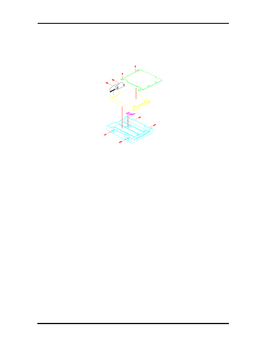
4-6 Field Service Guidelines
4.
To replace the floppy drive unit, remove the four small screws attaching it to the
null floppy disk drive assembly and remove the floppy disk drive cable.
5.
To replace the floppy disk drive module, reverse the above procedure.
Figure 4-2 Floppy Drive Module Assembly
Removing/Replacing the LCD Status Bar Cover and Hinges
Remove the LCD Status Bar Cover and Hinge Covers are as follows:
1.
Turn off the computer. Follow all disassembly procedures mentioned from the
start of this section.
2.
Slide the left and right hinge covers out to remove them.
3.
Lift the status bar cover out.
4.
To replace the LCD Status Cover and Hinge Covers, reverse the removal proce-
dures mentioned above.
Removing/Replacing the Keyboard
The procedure for removing and replacing the keyboard is as follows:
1.
Turn off the computer. Follow all disassembly procedures mentioned from the
start of this section.
2.
Lift the keyboard out and tilt the upper edge of the keyboard towards you, but do
not lift the keyboard away. Rest the keyboard (face down) on the palm rest area.
SOLD BY laptopia2005 DO NOT RESELL!!
SOLD BY laptopia2005 DO NOT RESELL!!

Field Service Guidelines 4-7
3.
Remove the keyboard cable from the system board’s FPC type connector. To re-
lease the keyboard cable from the connector, gently lift (using your fingernail or a
thin pointed object) the connector locks on the left and right edge. Pull the key-
board cable out and remove the keyboard from the notebook.
4.
To replace the keyboard; rest the keyboard face-down on the palm rest area. In-
sert the keyboard cable into the FPC type connector on the system board and tilt
the keyboard back into place.
Removing/Replacing the Heat Plate
This is a heat shield for the CPU and power board. Remember, the CPU is in contact with
this part, so be careful when removing it from the unit.
1.
Turn off the computer. Follow all disassembly procedures mentioned from the
start of this section.
2.
Remove the six screws and carefully lift the heat pipe from the unit.
3.
You do not need to remove this part if you are removing/replacing the LCD.
WARNING: The CPU is sometimes attached to
the heat pipe, so be careful not to damage the
pins or the CPU may be inoperable.
Removing/Replacing the CPU
The procedure for removing the CPU is as follows:
1.
Turn off the computer. Follow all disassembly procedures mentioned from the
start of this section.
2.
The CPU is located at the left rear of the system base assembly under the heat
pipe. The system board has been designed to allow the heat generated by the CPU
to be released from the system.
3.
Slowly remove the CPU, moving around each side, little by little. Avoid damaging
the CPU pins by forcing the CPU out of its slot immediately. Also, do not pull out
the CPU heat sink as it is part of the CPU. You must remove the CPU and the
heat sink together.
4.
To replace the CPU, align it with pin 1 of the socket and plug in the CPU. Make
sure that the CPU pins are straight before inserting it. Broken or damage pins on
the CPU may totally damage the CPU. To remount the CPU, reverse the disas-
sembly procedure mentioned above.
SOLD BY laptopia2005 DO NOT RESELL!!
SOLD BY laptopia2005 DO NOT RESELL!!

4-8 Field Service Guidelines
You do not need to remove this part if you are removing/replacing the LCD.
Removing/Replacing the Cover-Display LCD Assembly Module
The procedure for removing the Cover-Display LCD Assembly Module is as follows:
1.
Turn off the computer. Follow all disassembly procedures for removing the Hinge
Covers, Status Bar Cover, and Keyboard as mentioned earlier in this section.
2.
Remove the center screw on both hinge mounts, the grounding screw to the left
of the connector on the LED Board assembly, and remove the connector from the
LED board.
3.
Lift the Cover-Display LCD Assembly Module from off of the unit and set aside.
4.
To remount the Cover-Display LCD Assembly Module, reverse the disassembly
procedure mentioned above.
Removing/Replacing the System Top Cover Assembly and the NEC
VersaGlide Assembly
The procedure for removing and replacing the system top cover assembly and VersaGlide is
as follows:
NOTE: If you plan to continue remov-
ing/replacing modules from the notebook you
must follow all of the disassembly procedures
mentioned from the start of this section.
1.
Turn off the computer and remove the Battery, Hard Disk Drive, and Floppy Disk
Drive Modules. Follow all disassembly procedures mentioned from the start of
this section.
2.
Turn the System Unit upside down with the bottom facing up. Remove the nine
screws securing the base unit assembly from the top unit assembly.
3.
Return the back to the normal position. Remove the screw located between the
hinges above the LEDs. Next remove the screw located just under the speaker on
the left side, the screw just to the right of the LEDs and the screw located to the
right of the LCD cable connector. Lift the top cover from the base cover. Note,
that the LCD, speaker, and the VersaGlide cables are all still attached to the sys-
tem board. Pull these cables out and remove the whole top cover assembly.
4.
The VersaGlide module is assembled to the system top cover case. Turn the top
cover case over and locate the VersaGlide printed circuit board. Remove the six
screws securing the module and remove the VersaGlide assembly.
SOLD BY laptopia2005 DO NOT RESELL!!
SOLD BY laptopia2005 DO NOT RESELL!!
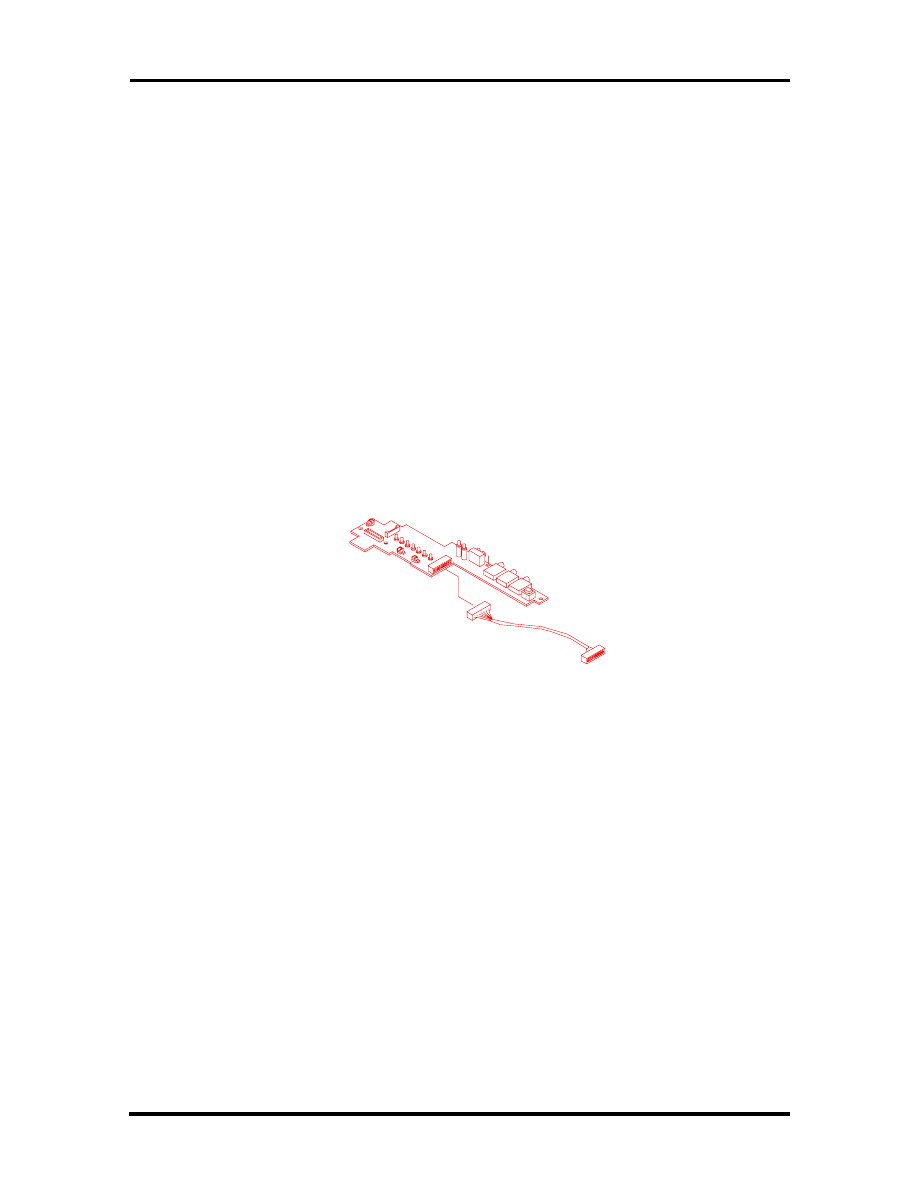
Field Service Guidelines 4-9
5.
To replace the whole top case assembly, reverse the removal procedures men-
tioned above. We recommend that you do the top cover screws first, then the
bottom cover screws. Make sure to test the VersaGlide before entirely securing it
to the top cover case.
6.
You do not need to remove the CPU unless you are going to replace it.
Removing/Replacing the LED Board
The procedure for removing the LED board is as follows:
1.
Turn off the computer. Follow all disassembly procedures mentioned from the
start of this section.
2.
The LED Board is located in the center rear of the system base unit. This board
alerts you to the processes presently in use on the computer.
3.
Remove the two screws and lift the board carefully out of the connections to the
system board.
Figure 4-3 The LED Board Module Assembly
Removing/Replacing the System Board and I/O Board
The system board and the I/O board are assembled together as one unit and must be re-
moved from the base unit before being separated from each other. The procedure for re-
moving the system board and I/O board is as follows:
1.
Turn off the computer. Follow all disassembly procedures mentioned from the
start of this section.
2.
Remove the two large posts from the center of the system board and the two
screws from the lower leg of the I/O Board.
3.
From the back of the unit remove the six spacers and two screws around the four
plug-in connectors.
SOLD BY laptopia2005 DO NOT RESELL!!
SOLD BY laptopia2005 DO NOT RESELL!!
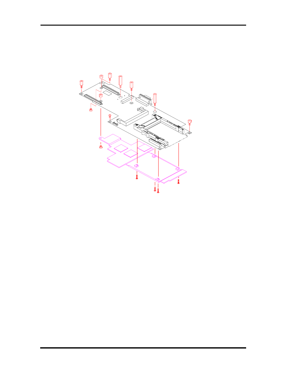
4-10 Field Service Guidelines
4.
Since the system board is the main unit of the notebook, all of the other boards
are connected to this electronic module either by connector or by cable. Special
care should be taken when removing this module, so as not to damage any of
these connectors and/or cables.
Figure 4-4 The System Board and I/O Boards
Separating the System Board and I/O Board
The system board is attached directly to the I/O board. The following procedure should be
taken to separate the two boards:
1.
Turn off the computer. Follow all disassembly procedures mentioned from the
start of this section.
2.
Remove the four medium spacers located along the top and left side edge and the
one screw located at the center bottom of the system board.
3.
Slowly separate the I/O Board and system board, being cautious about the con-
nectors coupling the two boards together.
4.
To reattach the I/O Board and system board, reverse the separation procedures
mentioned above.
SOLD BY laptopia2005 DO NOT RESELL!!
SOLD BY laptopia2005 DO NOT RESELL!!
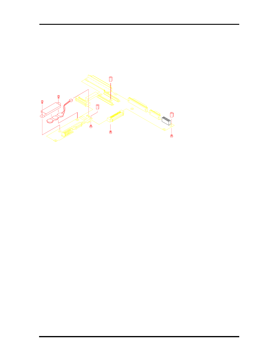
Field Service Guidelines 4-11
Figure 4-5 The I/O Board Module Assembly
SOLD BY laptopia2005 DO NOT RESELL!!
SOLD BY laptopia2005 DO NOT RESELL!!
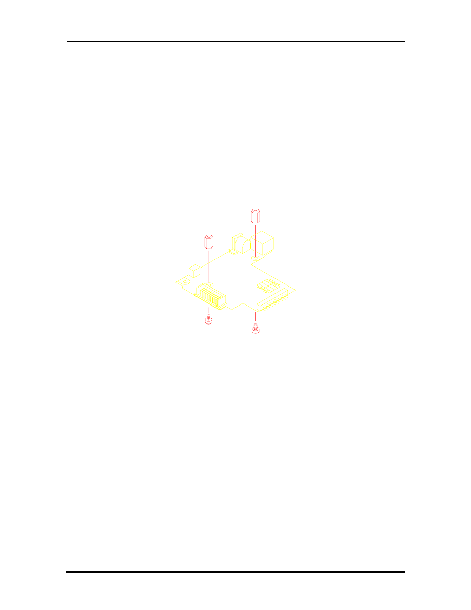
4-12 Field Service Guidelines
Removing/Replacing the Power Board
The procedure for removing the power board is as follows:
1.
Turn off the computer. Follow all disassembly procedures mentioned from the
start of this section.
2.
Remove the two hex spacers from the center of the board and lift the module from
the unit.
3.
To replace the power board module, reverse the removal procedures mentioned
above.
Figure 4-6 Power Board Module Assembly
SOLD BY laptopia2005 DO NOT RESELL!!
SOLD BY laptopia2005 DO NOT RESELL!!
Field Service Guidelines 4-13
ILLUSTRATED PARTS BREAKDOWN
This section contains the illustrated parts breakdown (IPB) and NEC part numbers for the
NEC Versa 2400 Series computer. Table 4-1 lists field-replaceable parts and corresponding
part numbers. Figure 4-7 shows the field-replaceable parts for the docking station.
Table 4-1 NEC Versa 2400 Series Field-Replaceable Parts*
Item
Description
Part Number
1
Main Battery (NiMH)
21-90128-31
2
TEAC CD-ROM Assembly
25-00242-00
3
AC Adapter
12-00118-30
4
AC Power Cord
22-30031-00
5
CMOS Battery
TBD
6
AC/DC Board Assembly
51-70187-10
7
VersaGlide Assembly
51-70185-11
8
Cover, Left Hinge
24-40827-00
9
U.S. Keyboard
71-30335-00
10
LCD Cable Assembly, 11.3”
22-20286-00
11
NEC Model Nameplate, NEC Versa 2400
NEC Model Nameplate, NEC Versa 2400CD
25-41033-00
25-41034-00
12
LCD Front Panel Assembly, 11.3”
24-40818-00
13
LCD, Hitashi, 11.3”
71-10469N00
14 LCD Inverter 12-00146-00
15
LCD Rear Cover, 11.3”
24-40819-0
16
NEC Logo
25-40851-00
17
Cover, Right Hinge
24-40828-00
18
Status Cover
24-408822-00
19
Top Cover Assembly
24-40821-00
20
CPU, Pentium, 100 MHz
CPU, Pentium, 133 MHz
51-90022-10
51-90024-10
21
I/O Port Casing
24-40810-10
22
Audio Cover
24-40826-00
23
LED Board Assembly
51-70184-00
24
System Board
51-70182-00
____________
*
This data was prepared September, 1996. For an up-to-date listing of spare parts, please call FastFacts
(800) 366-0476 and order document number 42200167
SOLD BY laptopia2005 DO NOT RESELL!!
SOLD BY laptopia2005 DO NOT RESELL!!

4-14 Field Service Guidelines
Table 4-1 NEC Versa 2400 Series Field-Replaceable Parts*
Item
Description
Part Number
25
I/O Board
51-70183-00
26
I/O Bracket
24-50204-00
27
810 MB Hard Disk Drive Assembly
1 GB Hard Disk Drive Assembly
25-00237-00
25-00238-00
28
Diskette Drive Assembly
24-70006-00
29
ROM Door
24-40810-10
30
Rubber Foot
24-80631-10
31
Bottom Cover Assembly
24-40793-10
32*
Speaker
24-80620-00
33*
Left Speaker Cable
22-20279-00
34*
Right Speaker Cable
22-20280-00
35*
Speaker Holder
24-50226-00
36*
Keyboard Bracket
24-50227-00
* Not shown in IPB figure.
SOLD BY laptopia2005 DO NOT RESELL!!
SOLD BY laptopia2005 DO NOT RESELL!!
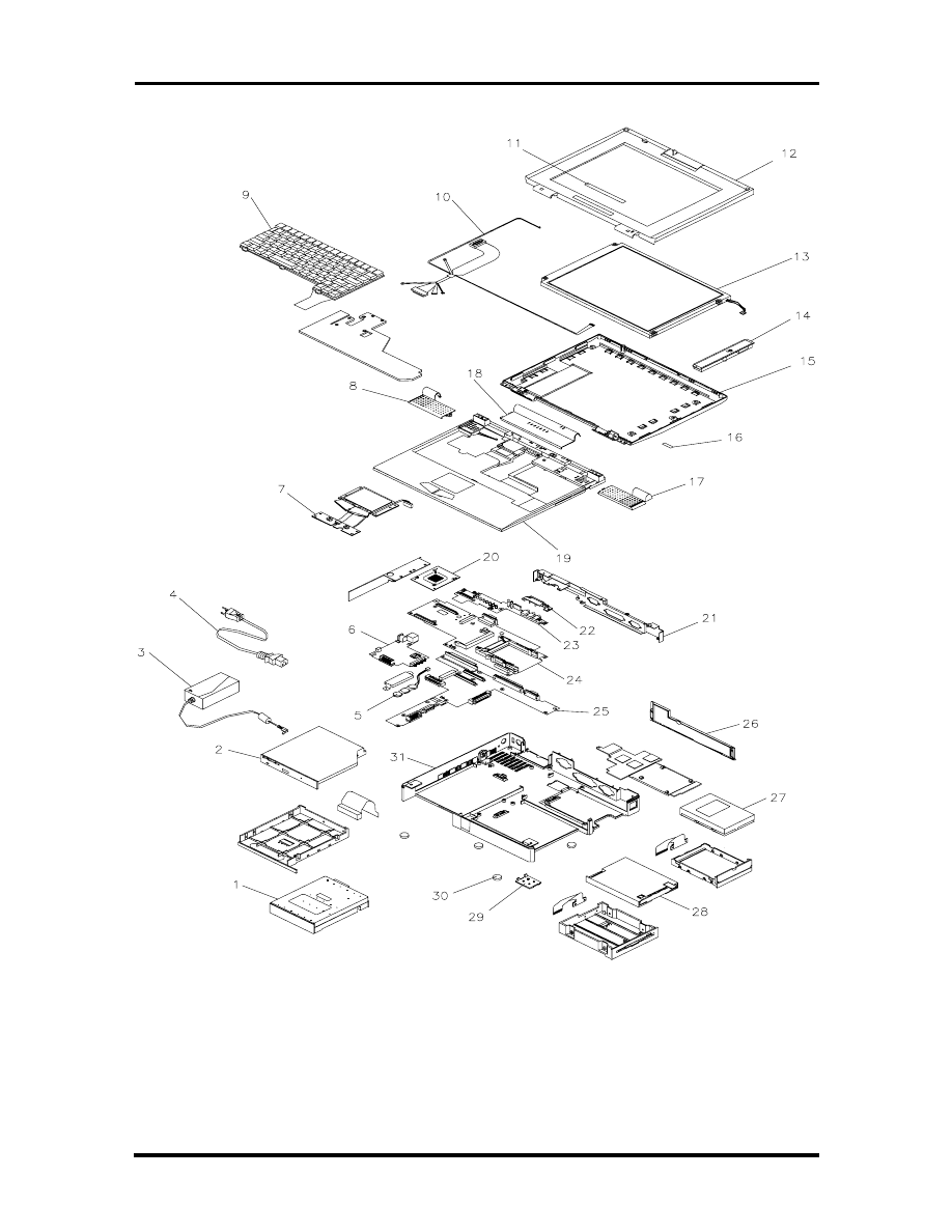
Field Service Guidelines 4-15
Figure 4-7 NEC Versa 2400 Series Illustrated Parts Breakdown
SOLD BY laptopia2005 DO NOT RESELL!!
SOLD BY laptopia2005 DO NOT RESELL!!
4-16 Field Service Guidelines
Packaging and Documentation
Packaging and documentation part numbers are listed in Table 4-2.
Table 4-2 Packaging and Documentation Part Numbers
Description
Model Number
NEC Versa 2400 Series User’s Guide
819-200134-000 Rev. 00
NEC Versa 2400 Series Service and
Reference Manual (this guide)
819-200167-000 Rev. 00
Shipping Carton
158-041012-000
Foam Insert
158-041014-000
Foam Insert
158-041014-001
SOLD BY laptopia2005 DO NOT RESELL!!
SOLD BY laptopia2005 DO NOT RESELL!!
Section 5
Troubleshooting and Repair
This section focuses on providing you with some information on notebook basic trouble-
shooting as well as the BIOS POST error codes and messages.
SERVICE INFORMATION
NEC service and information telephone numbers are listed in the following table.
Table 5-1 NEC Service and Information Telephone Numbers
Service
Call
To order NEC spare parts
In the U.S., call 1(800) 632-4525
To order options in the U.S.
Local Sales Office
To access the NEC Electronic Bulletin Board
System (BBS)
1(508) 635-4706
To download files - provides software drivers
and the latest ROM BIOS
1(508) 635-4706
NEC Service
In the U.S., call 1(800) 632-4525
Listen to the automated attendant and select the appropriate menu to reach one of
the following departments:
Information Center - literature, dealer locations, sales leads, response to ads
NSRC (National Service Response Center) - questions other than products,
spare parts or technical support
Service Contracts
TSC (Technical Support Center) - technical support for everyone else
FastFacts
TM
- automated service that sends
the latest information about NEC products to
the fax machine 24 hours a day
In the U.S., call 1(800) 366-0476
Outside U.S., 1(708) 860-9500 Ext. 2621
Canadian Inquiries
1(416) 795-3554
Technical Support
1-800-632-4525
TECHNICAL SUPPORT
NEC Technologies Technical Support Center (TSC) provides an E-mail service for Internet
users besides the support listed in Table 5-1. Technical questions regarding NEC products
can be sent over the Internet system to TSC. The Internet address is as follows:
tech-support@nectech.com
SOLD BY laptopia2005 DO NOT RESELL!!
SOLD BY laptopia2005 DO NOT RESELL!!

5-2 Troubleshooting and Repair
If it is more convenient, questions may also be faxed to TSC. The TSC fax number is:
(508) 635-4666
Along with the complete product name and question(s), be sure to included your name and
fax number or Internet address, so that an expert can respond to your question(s).
It would also be helpful to include your telephone number in case TSC can not get their an-
swer to you through the Internet or by fax. TSC will reply to all questions received by In-
ternet or fax within one business day.
PRODUCT INFORMATION
NEC FastFacts is an automated electronic information service used to obtain up-to-date
product application notes, installation procedures, troubleshooting tips, data sheets, techni-
cal information bulletins, price lists, and other information.
Information can be obtained from the FastFacts service 24 hours a day, 7 days a week. Us-
ing a touch-tone telephone, call the FastFacts number, order the desired information
through the automated attendant, and FastFacts will automatically send the information to
you.
Catalogs are available that list all of the documents and the document numbers. Current
catalogs include:
Catalog 1 - Monitors, Graphics Boards, and Data Projector Products
Catalog 2 - CD ROM Hardware and Software, Printers, and Disk Drive Products
Catalog 3 - Laptop, Desktop, and Server Computer Products
Catalog 9 - Price and Configuration Index
Ordering Information from FastFacts
Order information from FastFacts as follows:
1.
Check that the fax machine is on.
2.
Locate the document part number.
3.
Using a touch-tone telephone, call 1-800-366-0476 (U.S. and Canada only).
For international; enter the international long distance access number, the U.S.
telephone number, or the U.S. extension (01-708-860-9500 ext. 2621).
SOLD BY laptopia2005 DO NOT RESELL!!
SOLD BY laptopia2005 DO NOT RESELL!!

Troubleshooting and Repair 5-3
4.
Listen to the instructions provided by the automated attendant.
Press
1
to skip the FastFacts introduction and jump to the automated instructions
for ordering a document or catalog.
Press
2
for an introduction to FastFacts, followed by the automated instructions
for ordering a document or catalog.
5.
When asked by the automated attendant, enter your fax number and telephone
number.
For international; first enter the international long distance access number (011),
your country code, area or city code, and then your fax number.
The information requested will be automatically sent to your fax machine. If Fast-
Facts attempts to send the second order before the first order is completed, the
order may be canceled. After three tries, FastFacts assumes that the line is busy
and will not process the order.
HELPFUL STARTERS
Here are some helpful items to check before troubleshooting the notebook:
Is there any external power source connected to the computer?
Has the battery been fully charged?
Is the computer turned on and the POWER LED activated?
Is the LCD display control switch moved to its minimum level?
Is the LCD display switched to the external monitor?
Are all cables and devices connected properly and securely?
Have all needed device drivers been installed properly?
Have you checked the AUTOEXEC.BAT and CONFIG.SYS files for errors?
Is the Suspend Mode activated on the LCD Status Bar? Press any key or press the
power switch to wake system up again.
SOLD BY laptopia2005 DO NOT RESELL!!
SOLD BY laptopia2005 DO NOT RESELL!!
5-4 Troubleshooting and Repair
POWER ON SELF TEST (POST)
This section provides you with the Phoenix BIOS POST errors and messages summary.
Refer to this whenever you encounter error messages or beep codes generated by the com-
puter during startup.
POST Messages
The following is a summary of the Phoenix BIOS startup error messages that are displayed
on the notebook’s display. These messages will help you to understand many of the note-
book’s problems that may be corrected by entering the CMOS SETUP program and
checking the original values.
Table 5-2 POST Error Messages
Message
Possible Cause
Action
Diskette drive A failure
The drive failed or is
missing.
Check the drive to determine
the problem.
Diskette read failure -
press F1 to retry boot, F2
for SETUP utility
The diskette is either not
formatted or is defective.
Replace the diskette with a
bootable diskette and retry.
Display adapter failed,
using alternate
The primary video adapter
failed.
Check the primary video
adapter.
Gate A20 failure
The keyboard controller is
not accepting command,
specifically, the enable
and disable A20
command.
Check the keyboard
controller and system board.
Turn the power off, then back
on again. If the problem
persists contact qualified
NEC service personnel.
Fixed disk configuration
error
The specified
configuration is not
supported or doesn't
match the actual hardware
installed.
Correct the fixed disk
configuration.
Fixed disk controller
failure
The fixed disk may be
defective.
Try rebooting. If that doesn't
work, replace the fixed disk.
Fixed disk read failure-
press F1 to retry boot, F2
for SETUP utility
The fixed disk may be
configured incorrectly or is
defective.
Check the drive type selected
in SETUP. Try rebooting. If
that does not work, replace
the fixed disk.
Pointer device failure
The PS/2-style mouse
failed.
Try rebooting. If problem
persists, check the mouse,
it's cable and connector.
SOLD BY laptopia2005 DO NOT RESELL!!
SOLD BY laptopia2005 DO NOT RESELL!!
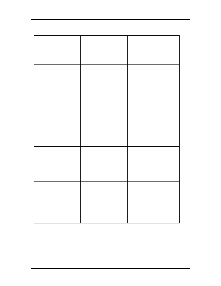
Troubleshooting and Repair 5-5
Table 5-2 POST Error Messages
Message
Possible Cause
Action
No boot device available -
press F1 to retry boot, F2
for SETUP utility
Either diskette drive A:,
the fixed disk, or both the
diskette and fixed disk are
defective.
Try rebooting. If problem
persists, replace the diskette
or the fixed disk.
No boot sector on fixed
disk - press F1 to retry
boot, F2 for SETUP utility
The C: drive is not
formatted or is not
bootable.
Format the C: drive and
make it bootable.
Not a boot diskette - press
F1 to retry boot, F2 for
SETUP utility
The diskette in drive A: is
not formatted as a
bootable diskette.
Replace the diskette with a
bootable diskette and try
rebooting.
No timer tick interrupt
The timer chip has failed.
Check the system board,
Turn the power off, then back
on again. If the problem
persists, contact qualified
service personnel.
Shutdown failure
Either the keyboard
controller is not accepting
the reset command or the
associated reset logic has
failed.
Check the keyboard
controller and system board.
Turn the power off, then back
on again. If the problem
persists, contact qualified
service personnel.
Time of day not set - run
SETUP program
Real Time Clock not set.
Run SETUP utility.
Timer 2 failure
The timer chip has failed.
Check the system board.
Turn the power off, then back
on again. If the problem
persists, contact qualified
service personnel.
F2 to enter ROM-based
SETUP
Invalid configuration
information must be
changed.
You must run SETUP utility
and correct configuration
information.
Invalid configuration
information - please run
SETUP
Display adapter is
configured incorrectly.
Memory size is incorrect.
Wrong number of diskette
drives.
Run the SETUP utility.
SOLD BY laptopia2005 DO NOT RESELL!!
SOLD BY laptopia2005 DO NOT RESELL!!
5-6 Troubleshooting and Repair
Table 5-2 POST Error Messages
Message
Possible Cause
Action
Keyboard clock line failure
The keyboard, the
keyboard cable
connection, or the
keyboard controller is
defective.
Make sure the keyboard
cable and keyboard are
connected properly. Check
the keyboard controller and
the system board. Turn the
power off, then back on
again. If the problem persists,
contact qualified service
personnel.
Keyboard data line failure
The keyboard controller
firmware has failed.
Check the keyboard
controller and system board.
Turn the power off, then back
on again. If the problem
persists, contact qualified
service personnel.
Keyboard stuck key failure
A key is jammed.
Locate the jammed key and
fix it. Make sure the keyboard
cable and keyboard are
connected properly. Turn the
power off, then back on
again. If the problem persists,
contact qualified service
personnel.
Memory failure at hex-
value, read hex-value,
expecting hex-value
Circuitry associated with
the memory chips has
failed.
Turn the power off, then back
on again. If the problem
persists, contact qualified
service personnel.
Unexpected interrupt in
protected mode
Hardware interrupt or NMI
occurred while in
protected mode.
Check the timer chip or the
interrupt controller on the
system board.
Real time clock failure
The RTC or battery failed.
Run SETUP and turn the
power off and on. If the
problem persists, replace the
RTC battery. If the problem
remains, contact qualified
service personnel.
SOLD BY laptopia2005 DO NOT RESELL!!
SOLD BY laptopia2005 DO NOT RESELL!!
Troubleshooting and Repair 5-7
Informational Messages
This section lists the messages that provide information to the user but require no action.
Table 5-3 BIOS Informational Messages
Message
Meaning
nnnK Base Memory
The amount of base memory that tested successfully.
nnnK Extended
The amount of extended memory that tested
successfully.
Memory tests terminated by
keystroke
The message indicate that a user pressed the
spacebar while memory tests were running and
stopped the memory tests.
Press the F1 key to continue
This message indicates that an error was found during
POST. Pressing the F1 key allows the system to
attempt to reboot.
Beginning memory test Press
the SPACEBAR to terminate the
memory test
A user can stop the memory tests by pressing the
spacebar.
Press the F1 key to continue, F2
to run the Setup utility
This message indicates that an error was found during
POST. Pressing the F1 key allows the system to
attempt to boot. Press F2 allows users to run the
ROM-based SETUP utility to correct configuration
information.
SOLD BY laptopia2005 DO NOT RESELL!!
SOLD BY laptopia2005 DO NOT RESELL!!
5-8 Troubleshooting and Repair
Run-time Error Messages
The following table lists run-time error messages.
Table 5-4 Run-time Error Messages
Message
Cause
Action
I/O card parity interrupt at
address. Type (S)hut off
NMI, (R)eboot, other keys to
continue
Memory on a peripheral card
has failed.
Check the memory cards
installed in the system.
Memory parity interrupt at
address. Type (S)hut off
NMI, (R)eboot, other keys to
continue
A memory chip(s) has failed.
Replace the system board.
Unexpected HW interrupt,
interrupt at address. Type
(R)eboot, other keys to
continue
Hardware problem. Not
displayed if the expected
interrupt handler is not
enabled.
Check all hardware in the
system.
Unexpected SW interrupt,
interrupt at address. Type
(R)eboot, other keys to
continue
Error(s) in the software
program. Not displayed if the
extended interrupt handler is
not enabled.
Turn the machine off and
then on again. If doesn’t
work, check the program.
Unexpected type 02 interrupt
at xxxxh. Type (S)hut off
NMI, (R)eboot, other keys to
continue
A parity error occurred, but
the source can not be
determine.
Turn the power off and then
on again.
SOLD BY laptopia2005 DO NOT RESELL!!
SOLD BY laptopia2005 DO NOT RESELL!!
Troubleshooting and Repair 5-9
QUICK TROUBLESHOOTING
This section summarizes problems that may develop during system operation and lists sug-
gested corrective actions.
Table 5-5 Quick Troubleshooting
Problem
Corrective Actions
No power
Check that the AC adapter is plugged into the
power connector of the system. Also, that the AC
adapter is plugged into a properly grounded AC
power outlet.
If using the battery as main power source, check
if the battery pack is of the right type, charged
and is inserted correctly.
Check the power board of the system. Is it
inserted into the system board connector
properly? Otherwise, replace the power board.
Data on the LCD is unreadable
Adjust the brightness and contrast display
controls found on the right side of the LCD panel.
Check if the LCD cables are inserted properly.
Check also connections inside the LCD panel.
Check if installed VGA driver is correct.
Check VGA controller chip on the system board
if there is any cold or loosed soldering.
Replace the system board.
LCD screen does not show data
Check the LCD Status Bar if Suspend mode is
activated. Press any key or press the power
button to resume operation and display.
Check if LCD cables are disconnected or loosed.
Check if the display output is switched to the
external monitor.
Check if the Contrast level is set to minimum.
Check if there is power.
Replace LCD Inverter board found inside the
LCD Panel.
SOLD BY laptopia2005 DO NOT RESELL!!
SOLD BY laptopia2005 DO NOT RESELL!!
5-10 Troubleshooting and Repair
Table 5-5 Quick Troubleshooting
Problem
Corrective Actions
Battery Power does not last
Make sure that the power management features
are enabled.
Recharge the battery pack for 1½ hour before
using again.
Replace the battery pack.
System halts during boot sequence
Check condition of selected bootload device
(diskette or hard disk) for bad boot track or
incorrect OS files.
Try booting from a new bootable diskette and
recopy or repartition hard disk.
Check for any BIOS error messages on the
display screen.
Replace system board.
I/O processing malfunctions
Check the connections of all internal devices.
Replace system board.
Diskette drive does not work
Check if floppy drive cable is connected
properly.
Check diskette type if correct and not faulty.
Replace diskette drive.
Replace system board.
Hard disk drive malfunction
Check if hard disk drive is set properly on CMOS
SETUP.
Check drive cables and connections.
Check if disk drive is good.
Replace the system board.
Memory malfunction
Check if the memory module is inserted properly.
Replace the memory module.
Replace the system board.
External keyboard or PS/2 mouse
doesn’t work
Check if keyboard or mouse are connected
properly. Check Y-cable if it is being used. Power
off system first before plugging in the device.
Replace the keyboard or mouse.
Replace the system board.
SOLD BY laptopia2005 DO NOT RESELL!!
SOLD BY laptopia2005 DO NOT RESELL!!
Troubleshooting and Repair 5-11
Table 5-5 Quick Troubleshooting
Problem
Corrective Actions
PCMCIA card does not work
Check the PCMCIA driver installation for any
IRQ or IO address conflict.
Check if the PCMCIA card is inserted properly
and all connections are set.
Replace the PCMCIA card.
Replace the system board.
Trackball doesn’t work
Check if trackball is enabled under CMOS Setup.
Check if PS/2 mouse driver is properly installed.
Check trackball cable inside the system if it is
inserted properly.
Remove trackball ring cover and clean the ball
and the rollers inside.
Replace trackball module.
Check the keyboard controller chip for any cold
or loosed soldering.
Replace the system board.
Serial device does not work
If using serial mouse, check if trackball option is
disabled under CMOS Setup.
Check if mouse driver is installed properly.
Check if serial device is connected properly.
Replace serial device.
Check the I/O controller chip on the system
board for any cold or loosed soldering.
Replace the system board.
Parallel device does not work
Check if all connections are properly set.
Check if external device is turned on.
Check I/O controller chip on the system board for
any cold or loosed soldering.
Replace the system board.
SOLD BY laptopia2005 DO NOT RESELL!!
SOLD BY laptopia2005 DO NOT RESELL!!
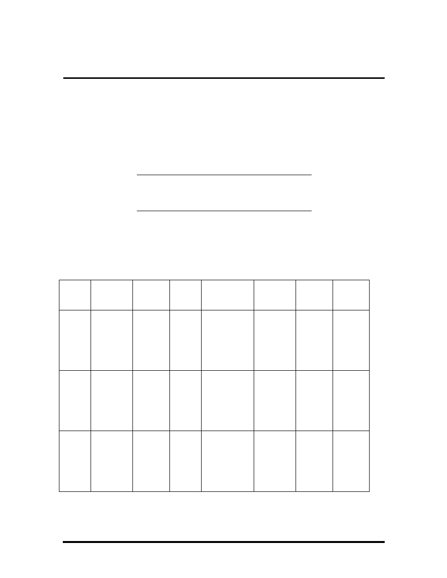
Appendix A
Video Modes
The C&T 65548 VGA chipset supports high resolution fixed frequency and variable fre-
quency analog monitors in interlaced and non-interlaced modes of operation. Digital moni-
tor support is also built-in. The tables in this section list all 65548 CRT monitor video
modes.
NOTE: The letter “I” under the Hex Mode col-
umn for the succeeding tables denotes Interlaced
monitors.
VGA STANDARD MODES
The following table lists VGA standard modes.
Table A-1 VGA Standard Modes (Text Mode)
Hex
Mode
No. of
Colors
Text
Display
Font
Size
Pixel Reso-
lution
Dot
Clock
MHz
Horiz.
Freq.
KHz
Vert.
Freq.
Hz
0, 1
16
40 x 25
40 x 25
40 x 25
9 x 16
8 x 14
8 x 8
360 x 400
320 x 350
320 x 200
28.322
25.175
25.175
31.5
70
2, 3
16
80 x 25
80 x 25
80 x 25
9 x
16
8 x
14
8 x 8
720 x 400
640 x 350
640 x 200
28.322
25.175
25.175
31.5
70
7
Mono
80 x 25
80 x 25
80 x 25
9 x
16
9 x
14
9 x 8
720 x 400
720 x 350
720 x 350
28.322
31.5
70
SOLD BY laptopia2005 DO NOT RESELL!!
SOLD BY laptopia2005 DO NOT RESELL!!
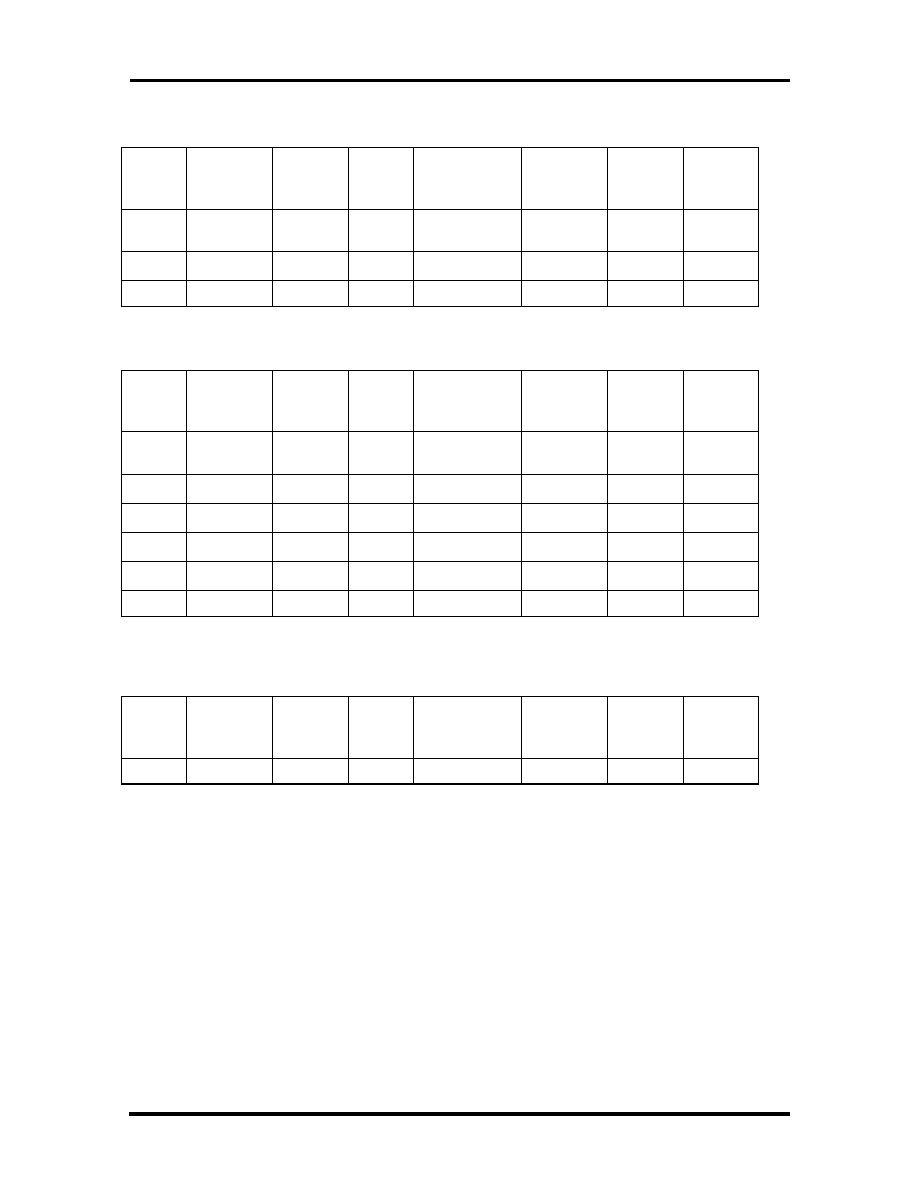
A-2 Video Modes
Table A-2 VGA Standard Modes (Graphics Mode)
Hex
Mode
No. of
Colors
Text
Display
Font
Size
Pixel Reso-
lution
Dot
Clock
MHz
Horiz.
Freq.
KHz
Vert.
Freq.
Hz
4
4
40 x 25
8 x 8
320 x 200
25.175
31.5
70
5
4
40 x 25
8 x 8
320 x 200
25.175
31.5
70
6
2
80 x 25
8 x 8
640 x 200
25.175
31.5
70
Table A-3 VGA Standard Modes (Planar Mode)
Hex
Mode
No. of
Colors
Text
Display
Font
Size
Pixel Reso-
lution
Dot
Clock
MHz
Horiz.
Freq.
KHz
Vert.
Freq.
Hz
D
16
40 x 25
8 x 8
320 x 200
25.175
31.5
70
E
16
80 x 25
8 x 8
640 x 200
25.175
31.5
70
F
Mono
80 x 25
8 x 14
640 x 350
25.175
31.5
70
10
16
80 x 25
8 x 14
640 x 350
25.175
31.5
70
11
2
80 x 30
8 x 16
640 x 480
25.175
31.5
70
12
16
80 x 30
8 x 16
640 x 480
25.175
31.5
70
Table A-4 VGA Standard Modes (Packed Pixel Mode)
Hex
Mode
No. of
Colors
Text
Display
Font
Size
Pixel Reso-
lution
Dot
Clock
MHz
Horiz.
Freq.
KHz
Vert.
Freq.
Hz
13
256
40 x 25
8 x 8
320 x 200
25.175
31.5
70
SOLD BY laptopia2005 DO NOT RESELL!!
SOLD BY laptopia2005 DO NOT RESELL!!
Video Modes A-3
VGA EXTENDED MODES
The C&T 65548 VGA BIOS supports standard VESA and extended modes, listed in the
following table.
Table A-5 VGA Extended Modes (Text Mode)
Hex
Mode
No. of
Colors
Text
Display
Font
Size
Pixel
Resolution
Dot Clock
MHz
Horiz.
Freq.
KHz
Vert.
Freq.
Hz
60
16
132 x 25
8 x 16
1056 x 400
40.0
30.5
68
61
16
132 x 50
8 x 16
1056 x 400
40.0
30.5
68
Table A-6 VGA Extended Modes (4-Bit Linear Mode)
Hex
Mode
No. of
Colors
Text
Display
Font
Size
Pixel Reso-
lution
Dot
Clock
MHz
Horiz.
Freq.
KHz
Vert.
Freq.
Hz
20
16
80 x 30
8 x 16
640 x 480
25.175
31.5
60
22
16
100 x 37
8 x 16
800 x 600
40.0
37.5
60
24
16
128 x 48
8 x 16
1024 x 768
65.0
48.5
60
24I
44.9
35.5
43
Table A-7 VGA Extended Modes (8-Bit Linear Mode)
Hex
Mode
No. of
Colors
Text
Display
Font
Size
Pixel Reso-
lution
Dot
Clock
MHz
Horiz.
Freq.
KHz
Vert.
Freq.
Hz
30
256
80 x 30
8 x 16
640 x 480
25.175
31.5
60
32
256
100 x 37
8 x 16
800 x 600
40.0
37.5
60
34*
256
128 x 48
8 x 16
1024 x 768
65.0
48.5
60
34I*
44.9
35.5
43
Table A-8 VGA Extended Modes (15-Bit Linear Mode)
Hex
Mode
No. of
Colors
Text
Display
Font
Size
Pixel Reso-
lution
Dot
Clock
MHz
Horiz.
Freq.
KHz
Vert.
Freq.
Hz
40*
32K
80 x 30
8 x 16
640 x 480
50.350
31.5
60
SOLD BY laptopia2005 DO NOT RESELL!!
SOLD BY laptopia2005 DO NOT RESELL!!
A-4 Video Modes
Table A-9 VGA Extended Modes (16-Bit Linear Mode) - 1MB Video
Memory Only
Hex
Mode
No. of
Colors
Text
Display
Font
Size
Pixel Reso-
lution
Dot
Clock
MHz
Horiz.
Freq.
KHz
Vert.
Freq.
Hz
41
64K
80 x 30
8 x 16
640 x 480
50.350
31.5
60
Table A-10 VGA Extended Modes (24-Bit Linear Mode)
Hex
Mode
No. of
Colors
Text
Display
Font
Size
Pixel Reso-
lution
Dot
Clock
MHz
Horiz.
Freq.
KHz
Vert.
Freq.
Hz
50*
16
80 x 30
8 x 16
640 x 480
65.0
27.1
51.6
Table A-11 VGA Extended Modes (Planar Mode)
Hex
Mode
No. of
Colors
Text
Display
Font
Size
Pixel Reso-
lution
Dot
Clock
MHz
Horiz.
Freq.
KHz
Vert.
Freq.
Hz
6A, 70
16
100 x 37
8 x 16
800x 600
40.0
38.0
60
72, 75
16
128 x 48
8 x 16
1024 x 768
65.0
48.5
60
72, 75I
44.9
35.5
43
Table A-12 VGA Extended Modes (Packed Pixel Mode)
Hex
Mode
No. of
Colors
Text
Display
Font
Size
Pixel Reso-
lution
Dot
Clock
MHz
Horiz.
Freq.
KHz
Vert.
Freq.
Hz
78
16
80 x 25
8 x 16
640 x 400
25.175
31.5
70
79
256
80 x 30
8 x 16
640 x 480
25.175
31.5
60
7C
256
100 x 37
8 x 16
800 x 600
40.0
37.5
60
7E*
256
128 x 48
8 x 16
1024 x 768
65.0
48.5
60
7EI*
44.9
35.5
43
SOLD BY laptopia2005 DO NOT RESELL!!
SOLD BY laptopia2005 DO NOT RESELL!!
Video Modes A-5
VGA HIGH REFRESH MODES
The following tables list VGA high refresh modes.
Table A-13 VGA High Refresh Modes (Packed Pixel Mode)
Hex
Mode
No. of
Colors
Text
Display
Font
Size
Pixel Reso-
lution
Dot
Clock
MHz
Horiz.
Freq.
KHz
Vert.
Freq.
Hz
30
256
80 x 30
8 x 16
640 x 480
31.5
37.5
75
32*
256
100 x 37
8 x 16
800 x 600
49.5
46.9
75
Table A-14 VGA High Refresh Modes (Planar Mode)
Hex
Mode
No. of
Colors
Text
Display
Font
Size
Pixel Reso-
lution
Dot
Clock
MHz
Horiz.
Freq.
KHz
Vert.
Freq.
Hz
12
16
80 x 30
8 x 16
640 x 480
31.5
37.5
75
6A, 70
16
100 x 37
8 x 16
800 x 600
49.5
46.9
75
Table A-15 VGA High Refresh Modes (Packed Pixel Mode)
Hex
Mode
No. of
Colors
Text
Display
Font
Size
Pixel Reso-
lution
Dot
Clock
MHz
Horiz.
Freq.
KHz
Vert.
Freq.
Hz
79
256
80 x 30
8 x 16
640 x 480
31.5
37.5
75
7C*
256
100 x 37
8 x 16
800 x 600
49.5
46.9
75
SOLD BY laptopia2005 DO NOT RESELL!!
SOLD BY laptopia2005 DO NOT RESELL!!

Battery Replacement
A lithium battery in your computer maintains system configuration information. In the event
that the battery fails to maintain system configuration information, NEC recommends that
you replace the battery.
WARNING: There is a danger of explosion if the battery is incorrectly replaced. Replace
only with the same or equivalent type recommended by the manufacturer. Discard used bat-
teries according to the manufacturer’s instructions.
Battery Disposal
Your bridge battery (not your main battery) is made of Nickel Metal Hybrid (NiMH). The
bridge battery must be collected, recycled, or disposed of in an environmentally-approved
manner.
Your main battery, made of Lithium Ion (Li-Ion), and your CMOS lithium battery are not
recyclable.
The incineration, landfilling, or mixing of Li-ION and NiMH batteries with the municipal
solid wasted stream is prohibited by law in most areas.
Contact your local waste management officials for other information regarding the environ-
mentally sound collection, recycling, and disposal of the batteries.
SOLD BY laptopia2005 DO NOT RESELL!!
SOLD BY laptopia2005 DO NOT RESELL!!

Index
A
AC adapter
connecting, 1-10
AC power adapter, 3-11
AC/DC adapter specifications, 2-16
B
Battery
discharged, 1-5
removing, 1-9
Battery charger specifications, 2-15
Battery compartment latch, 1-14
Battery compartment release lock, 1-9
Battery features, 3-11
Battery packs
handling, 4-2
Battery specifications, 2-14
Battery types, 1-9
BIOS, 3-3
BIOS informational messages, 5-7
BIOS Setup utility, 1-15, 3-3
BIOS upgrade procedure, 1-21
Bottom features, 1-14
C
CD-ROM reader specifications, 2-14
Cleaning the notebook
exterior, 4-1
interior, 4-2
CMOS battery
discharging, 1-17
COM 1, 1-13
Connecting an external PS/2 mouse, 1-11
Converter board specifications, 2-8
CPU, 1-2
P54CSLM, 3-3
removing, 4-7
D
DC/DC converter specifications, 2-15
DIMM module, 1-20
Disassembly
battery pack, 4-4
CPU, 4-7
diskette drive, 4-5
hard disk drive, 4-5
heat plate, 4-7
I/O board, 4-9
keyboard, 4-6
LCD, 4-8
LCD status bar cover, 4-6
LED board, 4-9
Power board, 4-12
required tools, 4-3
system board, 4-9
top cover, 4-8
VersaGlide, 4-8
Disassembly procedures, 4-4
Diskette drive
standard, 1-8
Diskette drive specifications, 2-13
E
Embedded numeric keyboard, 1-5
Environmental specifications, 2-21
EPROM chip, 3-3
External keyboard, 1-11
External monitor
connecting, 1-12
External VGA, 3-8
F
FastFacts, 5-2
Features, 1-2
Field service guidelines, 4-1
Field-replaceable parts list, 4-13
Floating point unit, 3-4
Fn keys, 1-6
Functional block diagram, 3-2
H
Hard disk drive compartment, 1-9
Hard disk drive specifications, 2-14
SOLD BY laptopia2005 DO NOT RESELL!!
SOLD BY laptopia2005 DO NOT RESELL!!

Index-2
Hard disk drives
protecting, 4-2
Hard disk subsystem, 3-10
Hardware reset switch, 1-10
HDD LED, 3-10
Hot key descriptions, 2-21
I
I/O board specifications, 2-10
I/O subsystem, 3-6
Illustrated Parts Breakdown (IPB), 4-13
Intel P54CSLM, 3-3
K
Keyboard, 1-5
Keyboard controller, 3-8
Keyboard specifications, 2-16
L
LCD cover switch, 1-4
LCD inverter board, 3-11
LCD quality
maintaining, 4-3
LED indicator board specifications, 2-9
LED status indicators, 2-13
M
Memory
DRAM, 3-6
ROM, 3-6
upgrading, 1-19
Memory compartment, 1-7
Memory compartment cover, 1-14
Memory configurations, 1-19
Memory controller, 3-5
Memory subsystem, 3-6
Microprocessor, 3-3
Model configurations, 1-1
N
NEC service telephone numbers, 5-1
NiMH battery, 1-9
features, 3-11
Num lock key, 1-6
P
Packaging and documentation
part numbers, 4-16
Part numbers, 4-13
PCMCIA controller, 3-9
PCMCIA slot
using, 1-8
PCMCIA sockets, 3-9
PHDisk utility, 1-21
POST messages, 5-4
Power board, 3-11
Power connector, 1-10
Power management modes, 2-19
Power specifications, 2-22
Power subsystem, 3-10
Power switch, 1-4
Power-on self test (POST), 1-15
Preventive maintenance, 4-1
Printer
connecting, 1-13
Product information
Using FastFacts, 5-2
PS/2 mouse, 1-11
Q
Quick troubleshooting, 5-9
R
Resolution, 3-8
Run-time error messages, 5-8
S
SCANDISK, 4-2
Separating the system and I/O boards, 4-10
Serial port, 1-13
Service information, 5-1
Setup utility, 1-15
menu, 1-15
Shock specifications, 2-23
Specifications
system, 2-1
Status indicators, 2-13
Status panel LEDs, 1-5
Subsystems, 3-1
System BIOS, 3-3
SOLD BY laptopia2005 DO NOT RESELL!!
SOLD BY laptopia2005 DO NOT RESELL!!

Index-3
System board specifications, 2-7
System configuration diagram, 1-3
System faetures, 1-2
System logic controller, 3-4
System processor, 3-3
System specifications, 2-1
System upgrades, 1-19
T
Technical support
contacting, 5-1
Transfer board specifications, 2-8
Troubleshooting checklist, 5-3
V
VersaGlide, 1-7
VersaGlide subsystem, 3-10
VGA extended modes, A-3
VGA high refresh modes, A-5
VGA port, 1-12
VGA standard modes, A-1
VGA VESA driver diskette, 1-12
Vibration specifications, 2-22
Video controller, 3-7
features, 3-7
Video modes, A-1
Y
Y-adapter, 1-11
SOLD BY laptopia2005 DO NOT RESELL!!
SOLD BY laptopia2005 DO NOT RESELL!!
Document Outline
- PROPRIETARY NOTICE
- Preface
- Contents
- FCC Statement
- Abbreviations
- Introduction
- General Specifications
- Hardware Functional Overview
- Field Service Guidelines
- ILLUSTRATED PARTS BREAKDOWN
- Troubleshooting and Repair
- Video Modes
- Battery Replacement
- Index
Wyszukiwarka
Podobne podstrony:
Service Manual NEC Versa 6050 Series Laptop
Service Manual NEC Versa 2000 Series Laptop
Service Manual NEC Versa 2600 Series Laptop
Service Manual NEC Versa 6000 Series Laptop
Samsung SGH 2400 service manual
Nec Versa LXI Owners Manual
hplj 5p 6p service manual vhnlwmi5rxab6ao6bivsrdhllvztpnnomgxi2ma vhnlwmi5rxab6ao6bivsrdhllvztpnnomg
Oberheim Prommer Service Manual
Korg SQ 10 Service Manual
MAC1500 service manual
Kyocera Universal Feeder UF 1 Service Manual
Proview RA783 LCD Service Manual
indesit witp82euy Service Manual
Glow Worm installation and service manual Hideaway 70CF UIS
Proview PZ456 LCD Service Manual
Glow Worm installation and service manual Ultimate 50CF UIS
więcej podobnych podstron