Self-Study Programme 376
Service Training
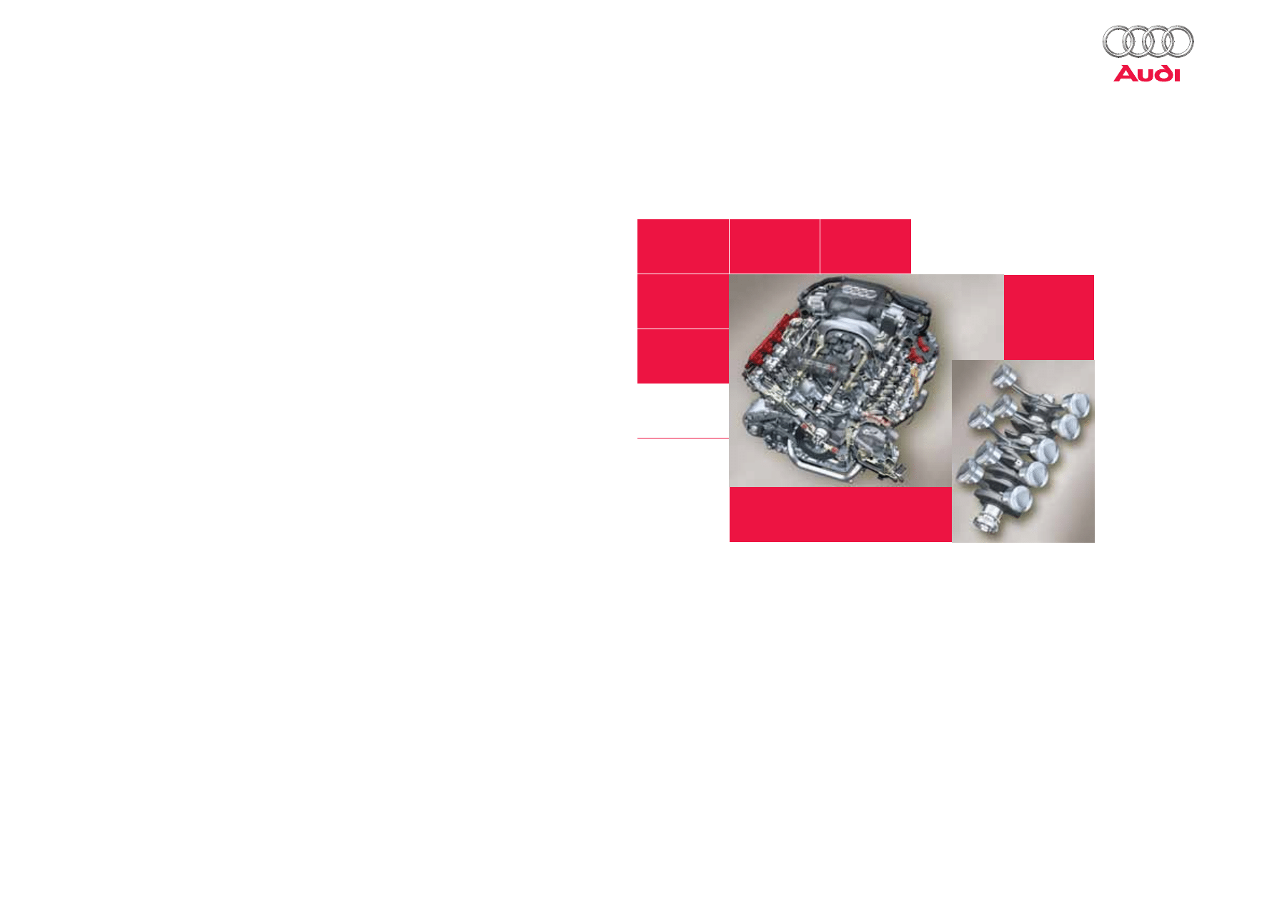
5.2 litre V10 FSI engine
376_003
Reference
Content-wise, this SSP supplements SSP 377.
For the first time in its history, Audi presents a high-performance ten-cylinder engine - the V10 FSI engine.
Fitted in the Audi S6 and S8 models, it underscores the specific attributes of pronounced sportiness and
supreme comfort. This combination of ten cylinders and FSI technology gives Audi a unique technological
position on the market.
The V10 belongs to the next generation of Audi V-engines, all of which have a 90-degree included angle and a
spacing of 90 millimetres between cylinder centres. Compared to the engine in the Lamborghini Gallardo, which
has a spacing of 88 millimetres between cylinder centres, the Audi engine has several new features in key areas.

Table of contents
The self-study programme teaches the design and function of new vehicle models,
new automotive components or new technologies.
The Self-Study Programme is not a Repair Manual!
The values given are intended as a guideline only and refer
to the software version valid at the time of publication of the SSP.
For maintenance and repair work, always refer to the current technical literature.
Note
Reference
5.2 litre V10 FSI engine
Performance features . . . . . . . . . . . . . . . . . . . . . . . . . . . . . . . . . . . . . . . . . . . . . . . . . 4
Basic engine . . . . . . . . . . . . . . . . . . . . . . . . . . . . . . . . . . . . . . . . . . . . . . . . . . . . . . . . . . 5
Crankshaft assembly . . . . . . . . . . . . . . . . . . . . . . . . . . . . . . . . . . . . . . . . . . . . . . . . . . . 6
Visco vibration damper. . . . . . . . . . . . . . . . . . . . . . . . . . . . . . . . . . . . . . . . . . . . . . . . . 7
Chain drive . . . . . . . . . . . . . . . . . . . . . . . . . . . . . . . . . . . . . . . . . . . . . . . . . . . . . . . . . . . 9
Cylinder head . . . . . . . . . . . . . . . . . . . . . . . . . . . . . . . . . . . . . . . . . . . . . . . . . . . . . . . . 10
Crankcase ventilation . . . . . . . . . . . . . . . . . . . . . . . . . . . . . . . . . . . . . . . . . . . . . . . . . 12
Oil circuit . . . . . . . . . . . . . . . . . . . . . . . . . . . . . . . . . . . . . . . . . . . . . . . . . . . . . . . . . . . . 14
Water circulation system . . . . . . . . . . . . . . . . . . . . . . . . . . . . . . . . . . . . . . . . . . . . . . 16
Air intake in the Audi S8 . . . . . . . . . . . . . . . . . . . . . . . . . . . . . . . . . . . . . . . . . . . . . . . 18
Fuel system in the Audi S8. . . . . . . . . . . . . . . . . . . . . . . . . . . . . . . . . . . . . . . . . . . . . 22
Exhaust system . . . . . . . . . . . . . . . . . . . . . . . . . . . . . . . . . . . . . . . . . . . . . . . . . . . . . . 26
System overview (Bosch MED 9.1) in the Audi S8 . . . . . . . . . . . . . . . . . . . . . . . . . 28
CAN data bus interfaces. . . . . . . . . . . . . . . . . . . . . . . . . . . . . . . . . . . . . . . . . . . . . . . 30
Operating modes . . . . . . . . . . . . . . . . . . . . . . . . . . . . . . . . . . . . . . . . . . . . . . . . . . . . . 31
4
Specifications
S6
S8
Engine codes
BXA
BSM
Type of engine
V10 engine with 90° included angle
Displacement in cm
3
5204
Max. power in kW (bhp)
320 (435)
331 (450)
Max. torque in Nm
540 at 3000 - 4000 rpm
Cylinder spacing in mm
90
Bore in mm
84,5
Stroke in mm
92,8
Compression ratio
12,5 : 1
Firing order
1–6–5–10–2–7–3–8–4–9
Engine weight in kg
approx. 220
Engine management
Bosch MED 9.1 - master-slave principle
Exhaust gas recirculation
internal
Exhaust gas treatment system
4 main catalysts, 4 pre-catalytic converters and 4 post-cat sensors
Exhaust emission standard
EU IV/LEV II
376_005
200
300
400
500
600
700
0
100
Nm
100
150
200
250
300
350
0
50
kW
2000
0
4000
6000
8000
240
320
400
480
560
720
640
0
80
Nm
120
160
200
240
280
320
360
0
40
kW
2000
0
4000
6000
8000
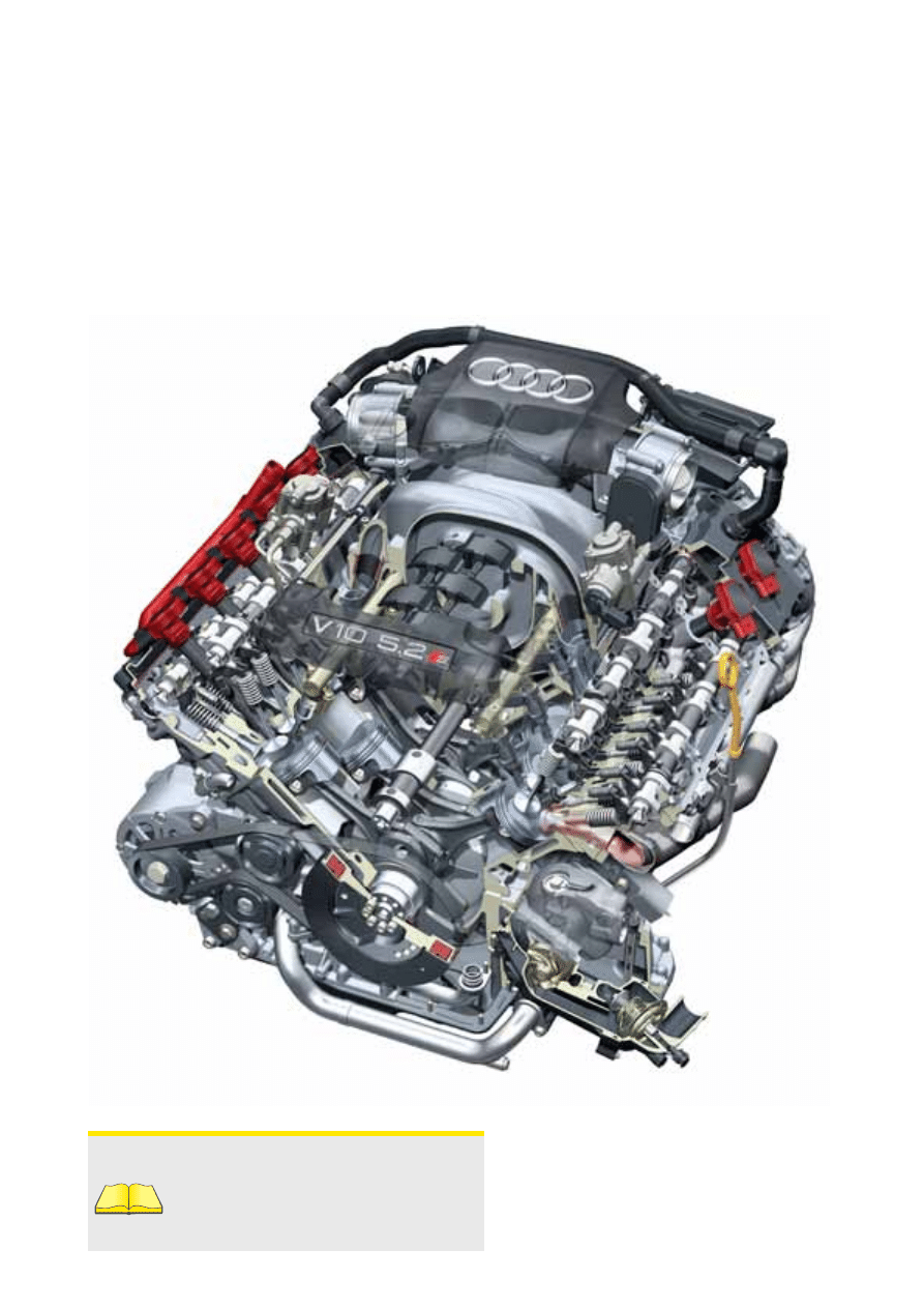
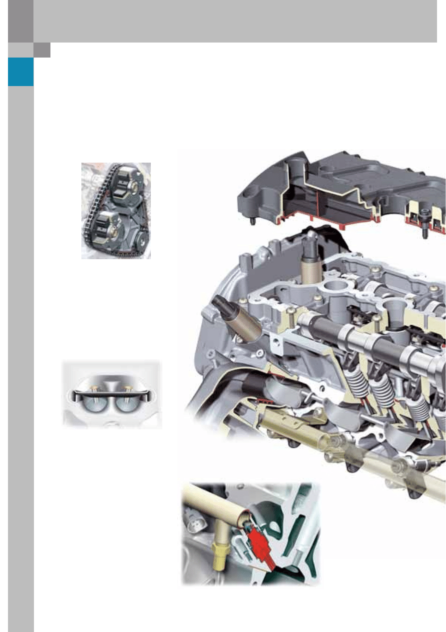
5.2 litre V10 FSI engine
Performance features
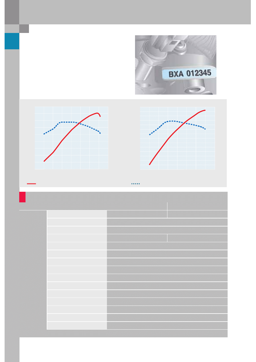
The engine code is located at the front above the
vibration damper on the right-hand side adjacent
the oil pressure switch.
Engine speed in RPM
Engine speed in RPM
Max. power in kW
Max. torque in Nm
Torque/power curve
Audi S8
Audi S6
5
376_006
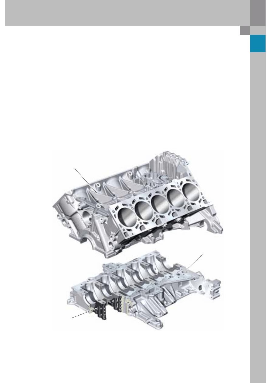
Basic engine
The V10 FSI engine is based on the V8 FSI engine,
which has, in principle, "only" been upgraded to
include an additional pair of cylinders.
The basic concept of the cylinder crankcase and the
cylinder heads, as well as the timing gear, the fuel
system and the intake manifold concept, have been
adopted unchanged.
Cylinder crankcase
Bedplate
Insert for crankshaft
main bearing
The AlSi12Cu1 bedplate has been reinforced with
cast-in GGG50 inserts which are attached with four
screws and through which the majority of the power
flow from the engine is transmitted.
These inserts also reduce thermal expansion and
play in the main crankshaft bearings at high
temperatures.
Crankcase
The cylinder crankcase with 90° included angle is a
bedplate construction and, with a length of 685 mm
and a width of 80 mm, it sets new standards for
compact design and overall length. The cylinder
crankcase, inclusive of bearing bushings and bolts,
weighs only approx. 47 kg.
The cylinder crankcase upper section is manufactured
as a homogeneous monoblock from AlSi17Cu4Mg
using the low pressure chill casting method.
On the other hand, the crankshaft with balancer
shaft, the double-chambered intake with dual
throttle valves, the exhaust manifold and the
ECU concept are features specific to the V10.
The benefits of this combination of materials are
high strength, minimal cylinder distortion and good
heat dissipation.
This technology made has it possible to dispense
with separate cylinder liners because the cylinder
liners are manufactured by mechanically stripping
the hard silicon crystals directly from the aluminium
alloy.
6
376_008
376_007
376_009
5.2 litre V10 FSI engine
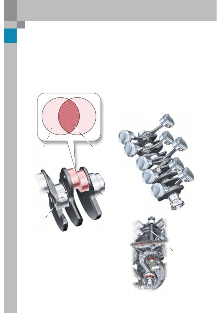
Crankshaft drive
Due to the 90° included angle, the crankshaft has
been forged as a split-pin shaft with a crank offset
of 18° in order to achieve an even firing interval of
72° crank degrees.
The split pin offset requires special strength treat-
ment because the crankshaft is most susceptible to
breaking at this so-called "overlap".
The first-order free moments of inertia are
compensated by a balancer shaft counter-rotating
at crankshaft speed.
This spheroidal cast iron balancer shaft runs in
two bearings and ensures a high level of engine
refinement. It is integrated in the chain drive D of
the ancillary units and is disposed in the vee space
between the cylinder banks.
Overlap
Split pin 18° crank degrees
Crank offset
Rolled main
bearing cavities
Induction-hardened
conrod journal cavity
This was achieved by toughening measures such
as rolling* the main bearing cavities and induction
hardening* of the conrod journal cavities.
A viscous damper lessens the torsional vibration at
the free end of the crankshaft facing the belt drive.
* Rolling: a roller under high pressure which rolls
off the rotating part of the workpiece.
This produces a high quality surface finish
and simultaneously strengthens the material.
* Induction hardening: heating of the workpiece
edge zone by means of induced eddy currents
whereby the core is not heated and remains soft
and ductile.
Balancer shaft
7
376_010
376_011
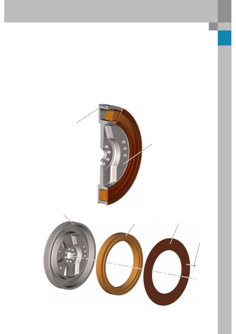
Viscous vibration damper
So-called vibration dampers are used to dampen
the torsional vibrations which occur at the free end
of the crankshaft due to the firing order of the
cylinders.
These vibration dampers usually have two metal
rings connected by a damping medium (elastomer-
rubber). A viscous damper is fitted in the V10 FSI
engine to absorb torsional vibration in the
crankshaft.
A viscous oil filled ring on the belt pulley is used
as a damping medium. This viscous oil buffers the
relative movement between the damping element
and the belt pulley housing.
The result is a reduction in the torsional vibration
of the crankshaft and hence also the torsional
irregularity of the belt wheel.
At the same time, it reduces the load on the ribbed
V-belt.
Vibration damper housing
Damping element
Cover disc
Locating pin
Ribbed V-belt track
Crankshaft counterweight
8
376_012
376_024
376_046
5.2 litre V10 FSI engine
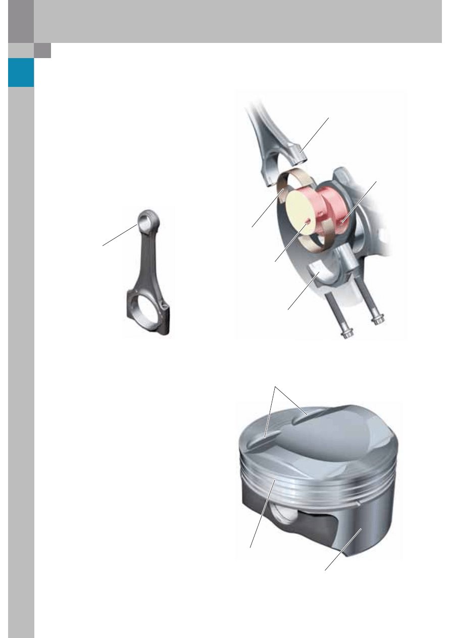
Conrods
The trapezoidal-type conrods are manufactured
from a high-strength cracked material (36MnVS4)
and broken at a predetermined position in the
production process.
This produces a structural break at the parting point
and ensures a high degree of joining accuracy
whereby only these two parts fit together perfectly.
The conrods and their bearing bushings are
lubricated through oil bores running from the main
bearing to the conrod journal.
Pistons
The cast aluminium pistons, made by Kolben
Schmidt, have a special crown shape that has been
adapted to the FSI combustion process in order to
promote charging (tumble effect) and impart a
tumbling motion of the air-fuel mixture induced in
homogeneous-charge mode.
The piston skirt is coated with a wear-resistant
iron anti-friction liner which minimises the wear of
the piston bearing surface under compressive load.
Oil spray nozzles cool the piston crown from
beneath and simultaneously lubricate the gudgeon
pin bearings.
Trapezoidal conrod
Three-component
big-end bearing
Transverse bore
from the crankshaft
Conrod bottom end
Oil supply bore in
the big-end bearing
Valve pockets
Piston top land
Iron liner
Trapezoidal conrod
9
376_014
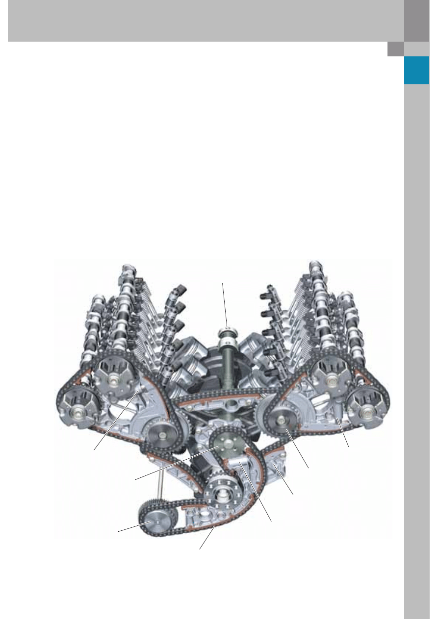
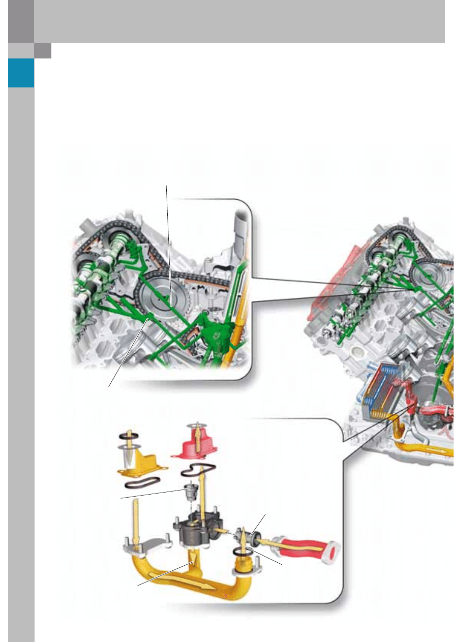
Chain drive
The timing gear with flywheel side chain drive is a
key building block with synergy potential within the
vee engine family due to its advantages in terms of
compactness.
Chain drive is provided by four 3/8“ roller chains
arranged on two planes.
Chain drive A, acting as a distributor drive, from the
crankshaft to the idler gears, and chain drives B
and C, acting as cylinder head drives, from the idler
gears to the camshafts.
Chain drive D, acting as an ancillary units drive, drives
not only the oil and water pumps, air conditioner
compressor and power steering pump, but also the
balancer shaft.
The balancer shaft is mounted in the vee space
between the cylinder banks and rotates in the
opposite direction at engine speed in order to
counteract first-order mass moments of inertia.
The latter evidence themselves as vibrations, noises
and uneven running of the engine in cer tain speed
ranges.
The balancer shaft, adapted to the V10 engine,
ensures a high level of engine refinement and must
be installed in the correct position in the chain drive
after repair work has been done.
Hydraulic tensioners with non-return valves are
used as a tensioning system and, like the chains,
they are designed for lifetime use.
Balancer shaft
Hydraulic tensioner
for chain drive B
Power take-off for:
– Oil pump
– Water pump
– A/C compressor
– Hydraulic pump
for power steering
3/8" simplex roller chain
for all chain drives
Hydraulic tensioner
for chain drive A
Hydraulic tensioner
for chain drive D
Balancer shaft drive
Idler gear
Hydraulic tensioner
for chain drive C
10
5.2 litre V10 FSI engine
An inserted partition plate divides the intake
port into an upper half and a lower half.
The camshaft is adjusted by means
of vane adjusters, whereby the
actuators are locked mechanically
by lokking bolts at engine start until
the required oil pressure level is
reached.
The adjustment range of the variable
camshaft adjuster is 42° at the intake
and exhaust ends.
The injectors and the injection nozzle
are mounted directly in the cylinder
combustion chamber so that fuel is
injected at an angle of 7.5°.
Cylinder head
The cylinder head of the new V10 FSI engine is based on the identically designed Audi 4V FSI cylinder head
concept.
Design features are spark plugs mounted at the centre of the cylinder heads and solenoid controlled injection
nozzles at the intake end. The built-up hollow camshafts rotate in bearings in the cylinder head and are bolted
to a ladder frame.
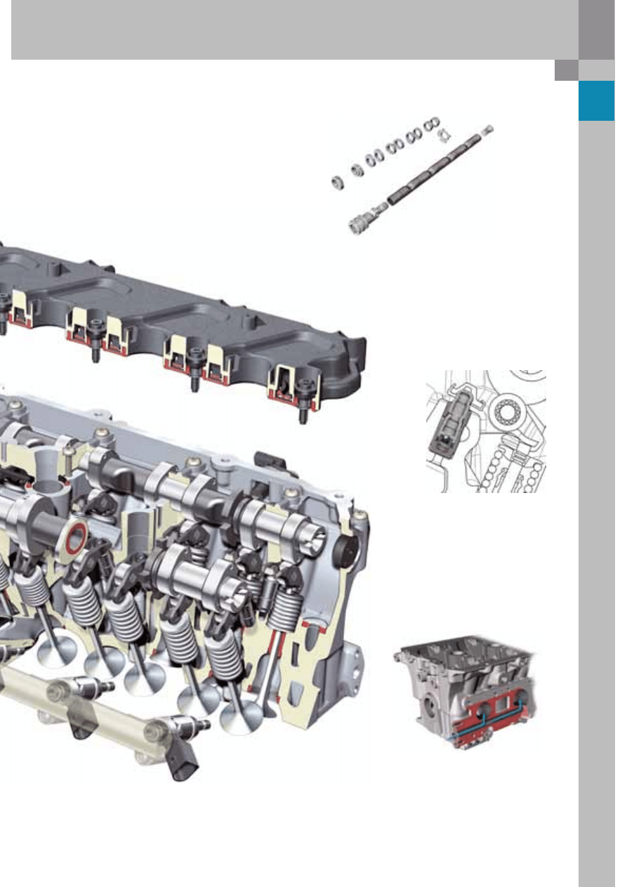
11
376_013
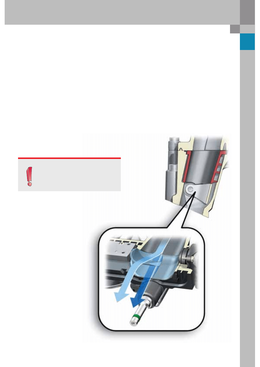
Hydraulic valve clearance compensation
elements are supplied with hydraulic oil
through transverse bores in the cylinder
head and provide backlash free valve
actuation.
Additional air flows through a port in the
cylinder head to each exhaust port in order
to burn the rich fuel-air mixture downstream
of the exhaust valves after cold starting
(catalytic converter start).
To reduce the weight of rotating parts, the camshafts are
manufactured from a hollow tube and mount-on cams.
They actuate roller cam followers with hydraulic
valve clearance compensation, as well as the intake
valves and the sodium cooled exhaust valves.
The intake ports have baffle plates to enhance the
tumble effect.
12
376_017
5.2 litre V10 FSI engine
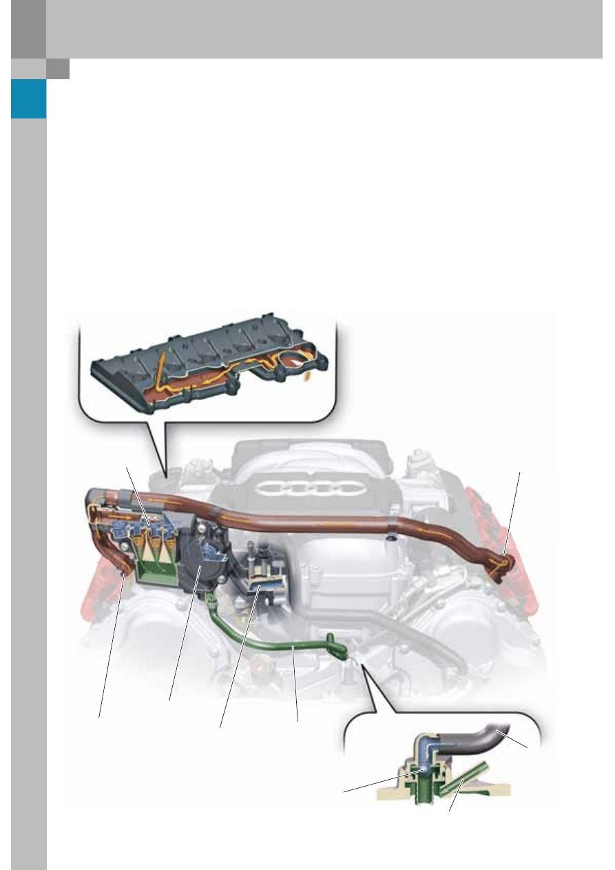
Crankcase ventilation
The blow-by gases produced by the combustion
process flow through the cylinder heads and into
the valve covers.
Both valve covers channel the blow-by gases
internally to the fine oil separator via baffles acting
as gravity oil separators and via a system of hoses.
The fine oil separator takes the form of a three-
stage cyclone with bypass whereby the oil content
in the blow-by gases is approx. 0.1 g/h after passing
through the cyclone. This method of fine oil
separation effectively prevents coking of the intake
valves.
After leaving the throttle valve the blow-by gases
flow to the combustion chamber via a two-stage
pressure limiting valve. The inlet is heated via the
coolant system in order to prevent freezing in
extremely cold weather.
Additional air for the PCV system (Positive Crankcase
Ventilation) is extracted downstream of the air filter
and flows via a non-return valve into the crankcase in
the vee space between the cylinder banks.
Mixing the blow-by gases with clean air ensures a
low water and fuel content in the engine lubricating
oil and reduces oil nitration.
Crankcase ventilation via
valve cover on the right
Three-stage
cyclone fine oil
separator
Double pressure control valve
Water heated
crankcase breather
port in the intake
manifold
Oil separator
return line
to vee space
between
cylinder banks
Crankcase ventilation via
valve cover on the left
Non-return valve for
crankcase ventilation in
case of excess pressure
in the cylinder crankcase
Oil return from the cyclone fine oil
separator at idle and engine off
Clean air from
the air filter
13
376_018
376_035
376_036
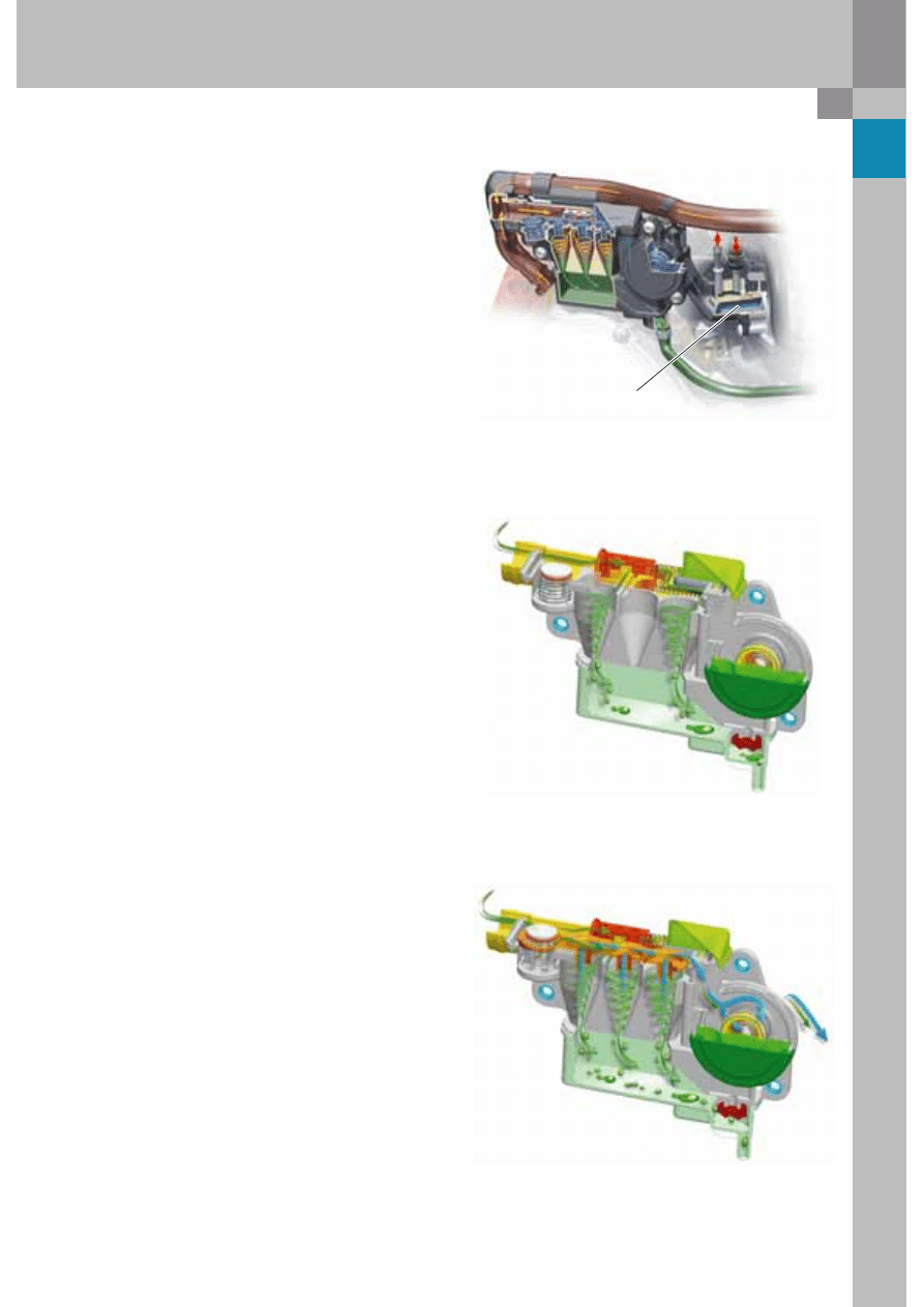
The mass flow rate of the blow-by gases increases
with increasing engine speed. The higher the mass
flow rate, the higher the force acting on the control
piston.
The control piston therefore pushed against the
pressure of the spring and opens up access to one
or more cyclones.
Three-stage cyclone fine oil separator
The quantity of gas in the blow-by gas is dependent
on engine load and speed.
Fine oil separation is achieved by means of a three-
stage cyclone.
One, two or three cyclones are operated in parallel
depending on gas flow since cyclone oil separators
can only separate efficiently a small proportion of
the volumetric flow.
Piston ring wobble can occur at very high engine
speeds and low engine loads, causing the pressure
inside the crankcase to increase, which can result in
very high gas flow rates.
This cyclones cannot cope with this pressure
increase, and the pressure would continue to rise
due to backpressure.
The bypass valve in the fine oil separator opens as a
result of the pressure increase. A proportion of the
blow-by gases is able to bypass the cyclones and
flows directly to the intake manifold via the pressure
limiting valve.
The separated oil which has been collected flows
into the vee space between the cylinder banks via a
valve which opens under the weight of the oil.
Crankcase ventilation
via valve cover on left
14
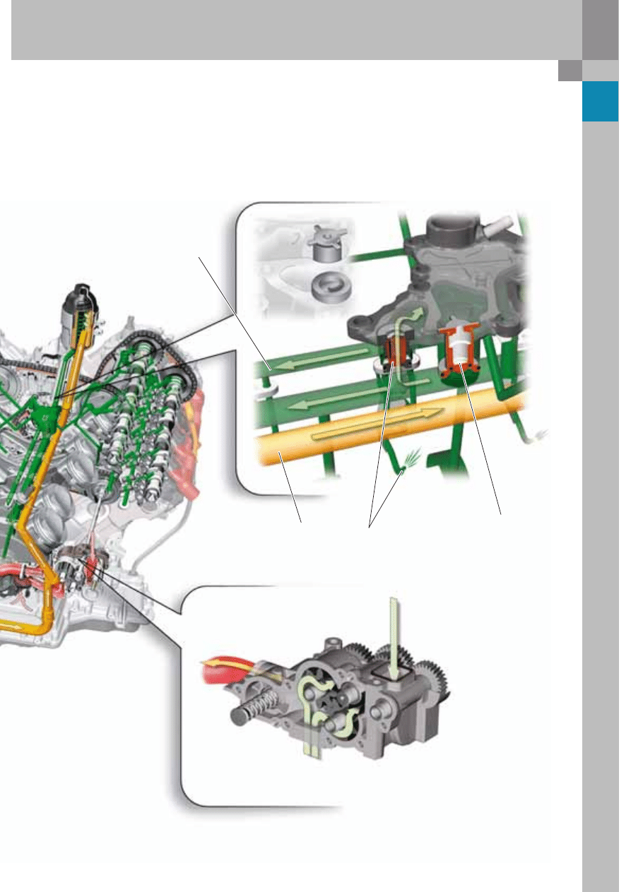
5.2 litre V10 FSI engine
Oil supply to the oscillating motors
and chain tensioner
Oil supply for lubricating the camshafts,
valve clearance compensation elements and rocker shafts
Oil cooler return
Oil cooler inlet
Oil cooler
Bypass valve
Oil retention valve
Oil inlet
Oil cleaner
Bypass
Oil circulation system
Design - component overview
The oil circulation system of the V10 FSI engine is of classic wet sump construction. The oil flow rate,
approx. 55 l/min at 7000 rpm and 120 °C, and hence also the power consumption of the oil pump, have been
reduced by optimising the clearance of the low-friction bearings.
15
376_015
In addition, the oil supply to the camshaft adjusters and the chain modules on the cylinder head side was
separated from the oil supply to the camshaft bearings and the hydraulic elements in order to reduce the
oil pressure in the cylinder head and optimise oil supply to the camshaft adjusters.
Oil inlet to oil cleaner
Oilway to the piston
cooling nozzles
Oil retention valve for
both cylinder heads
Pressure valve for oil spray
cooling of the pistons
16
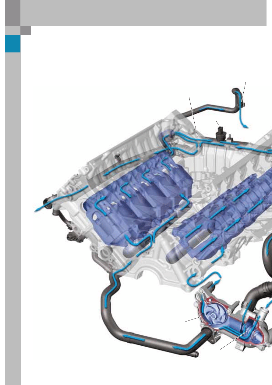
5.2 litre V10 FSI engine
to
radiator
to
right engine side
When the coolant thermostat
is open, the branch-off to the
primary cooling circuit is here.
Due to the high power density, the intake valves -
which are subject to high thermal stresses - are
cooled via additional bores between the intake
valves.
Coolant temperature
sender G62
to the heating
heat exchanger
Water circulation system
The cooling system in the 5.2 litre V10 FSI engine is
configured as a longitudinal flow cooling system.
Coolant flows from the coolant pump to the engine
block on the left and right-hand sides and around
the cylinders.
Then it flows upwards inside the cylinder head and
longitudinal to the chain housing to the return line.
Depending on the position of the coolant regulator,
the coolant is directed either directly to the coolant
pump or via the radiator to the water pump.
Coolant thermostat
Coolant pump
17
376_042
376_041
376_040
376_038
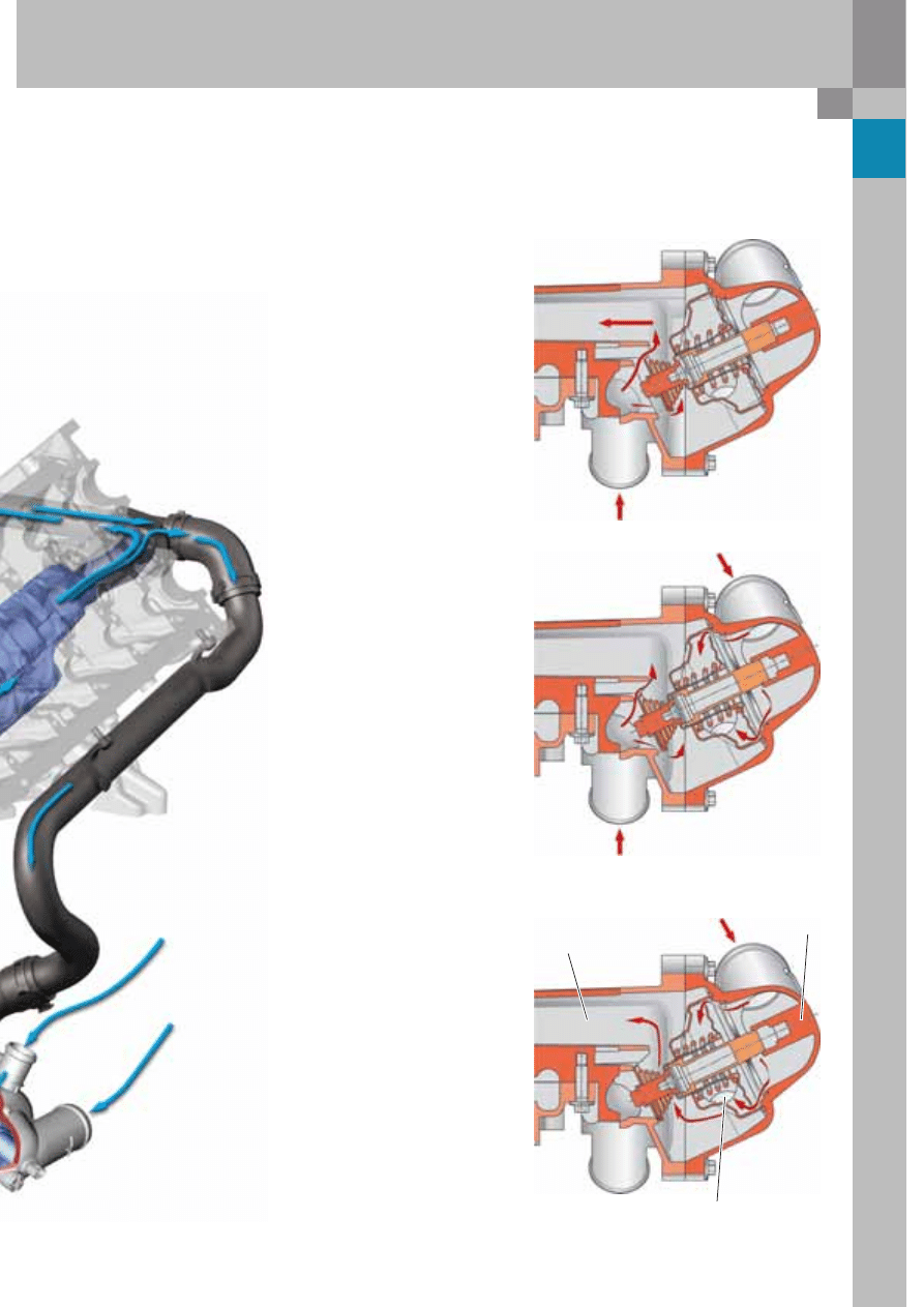
The coolant temperature is regulated to between 90 °C and 105 °C by
the engine control unit via an electrically heated coolant thermostat.
Coolant thermostat deenergised,
coolant cold
The coolant thermostat closes the
inlet from the radiator completely
and opens the return port, activating
the secondary cooling circuit.
Coolant thermostat deenergised,
coolant hot - coolant thermostat
is in an intermediate position
The inlet from the radiator is
partially open and the return line
from the engine is partially closed.
The coolant temperature is
regulated to approx. 105 °C in part-
load operation to allow the engine
to run at reduced friction (the oil
temperature rises).
Coolant thermostat is energised
at full throttle by a PWM signal
The coolant thermostat opens the
inlet by fully opening the radiator
and simultaneously closes the
engine's return port.
Due to the large cooling surface of
the radiator, coolant temperature
can be reduced to 90 °C at full
throttle in order to reduce the knock
tendency of the engine (lower
combustion chamber temperature).
Furthermore, better carburetion
is achieved due to the reduced
intake air temperature.
from radiator
to intake side
of coolant pump
electrical
connections
Return line from heater
heat exchanger
from radiator
from return line
Engine
from
radiator
from
heater heat
exchanger
18
376_019
5.2 litre V10 FSI engine
A soundpipe accentuates the sound typical of the
V10 at high engine loads.
This soundpipe transmits the intake noise produced
by charge cycles into the vehicle interior through a
special membrane-foam composite filter.
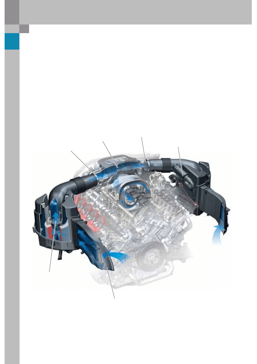
Air intake in the Audi S8
Intake system
The air intake on the V10 engine is double-chambered
on account of the engine's high power output.
The left and right hand air filters have switchable
flaps to induce extra air from the engine bay at high
air flow rates and reduce the pressure loss in the
system.
After passing through the flow optimised air filter,
the intake air flows via two hot-film air mass meters
seated directly on the air filters and through two
throttle valves with a diameter of 68 mm into central
intake manifold headers.
Air intake right
in front end
Air intake left
in front end
Air mass meter
Throttle valve 1
Intake manifold header
Throttle valve 2
Soundpipe
19
376_045
Note
The intake manifold flaps (tumble flaps) are
always open when they are deenergised.
Intake manifold flaps
Like the variable inlet manifold, the intake manifold
flaps are map-controlled in both engine variants.
The intake manifold flaps in both engines are
activated at the bottom end of engine load and
speed ranges.
They are brought into abutment with the baffle
plates in the cylinder head and thereby close of the
bottom section of the intake port. The induced air
mass now flows through the upper section of the
intake port and creates a tumbling charge motion
within the cylinder.
The intake manifold flaps are open while inactive,
thus allowing air to flow through the full port cross-
section. All flaps in a cylinder bank are attached to a
common shaft.
In the basic engine the intake manifold flaps are
activated by an electrical actuator.
A Hall sensor monitors the position of the intake
manifold flaps for each cylinder bank.
In the high revving engine, the intake manifold flaps
are switched by a vacuum actuator, with there being
a separate actuator for each cylinder bank. Again,
feedback on flap positions is provided by Hall
sensors.
20
376_016
5.2 litre V10 FSI engine
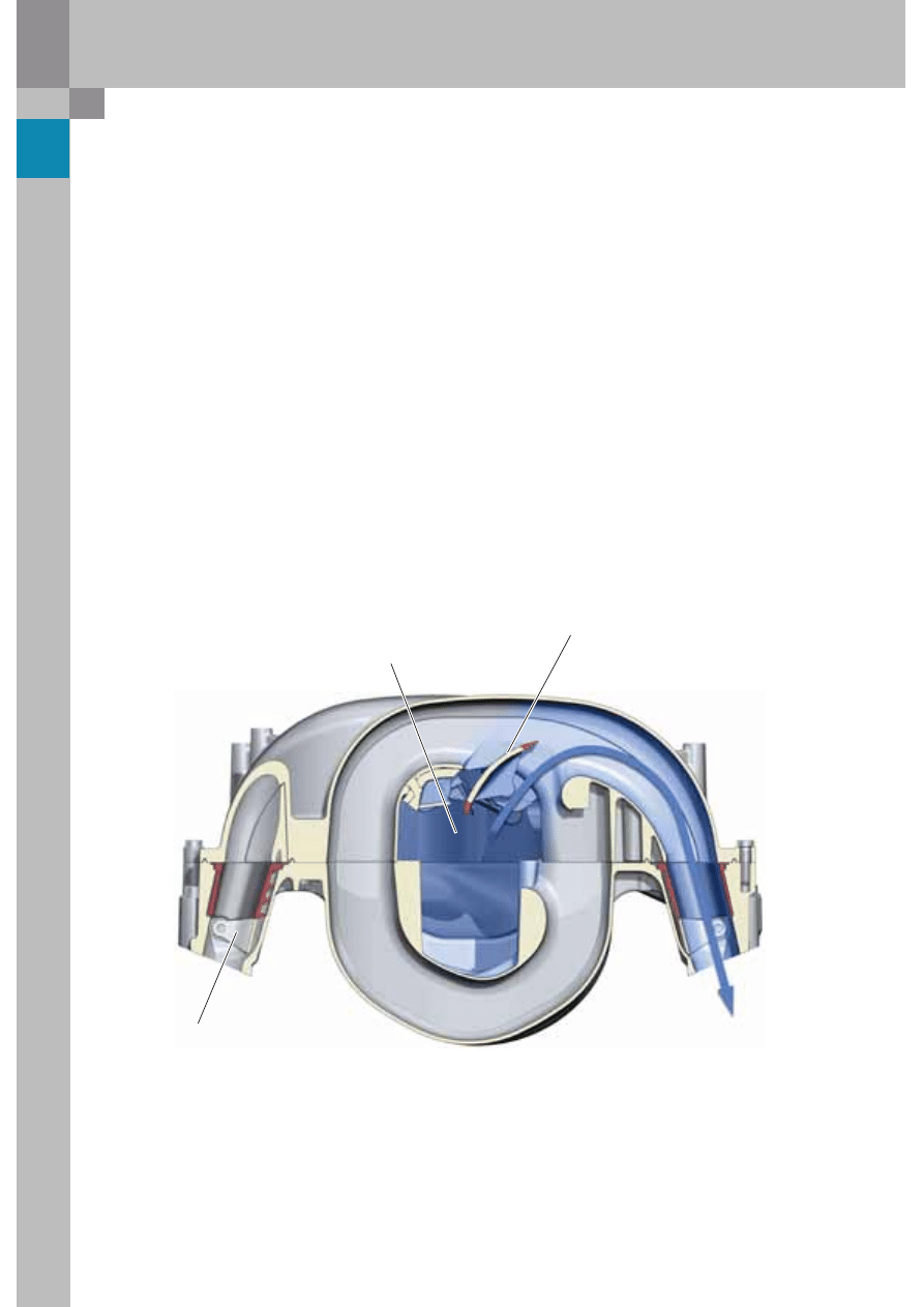
Variable inlet manifold
The V10 FSI engine has a four-piece variable intake
manifold made from die-cast magnesium.
The control shafts are operated by an electric motor,
whereby the switching of the intake manifold
lengths is map-controlled.
To minimise inner leakage, the intake manifold flaps
have silicone rubber lip seals.
The flap system is integrated in the upper section of
the intake manifold. The intake manifold flaps are
positioned based on a characteristic map by the
engine control unit by an electric motor.
At low engine loads/speeds, the intake manifold is
switched to the short intake path. The flaps are
positioned flush against the intake manifold in
order to avoid flow losses due to vorticity.
Short intake path:
Variable intake manifold flap open
Intake manifold flaps
Variable intake manifold flaps
with silicone rubber seal
The variable intake manifold length in the power position (short path) is 307 mm.
Central intake manifold header
21
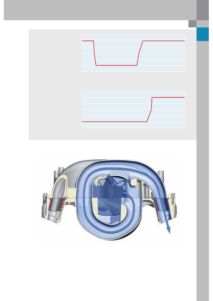
2,5
2
1,5
1
0,5
0
-0,5
0
1000
2000
3000
4000
5000
6000
7000
0
1000
2000
3000
4000
5000
6000
7000
2,5
2
1,5
1
0,5
0
-0,5
The variable intake manifold is 675 mm long in the torque position (long distance).
Long intake path:
In the medium engine load/speed range the flaps are switched to the long intake path. The induced air is
routed in a wide arc in order to provide increased air charging of the cylinders.
Intake manif
old position
long – short
Intake manif
old position
long - short
Variable intake
manifold switching
at low engine loads
Variable intake
manifold switching
at high engine loads
Engine speed
Engine speed
Variable intake manifold flaps closed
22
5.2 litre V10 FSI engine
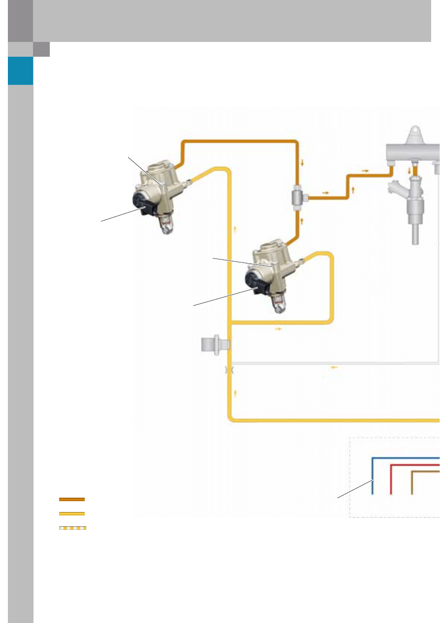
Fuel system in the Audi S8
Leakage line
Fuel pressure sender,
low pressure G410
Fuel metering valve N290
High-pressure
fuel pump 2
Fuel metering valve 2 N402
High-pressure
fuel pump 1
High-pressure
Low pressure
Pressureless
adjusted to 100 bar
PWM signal from
engine control unit
Terminal
30
Terminal
31
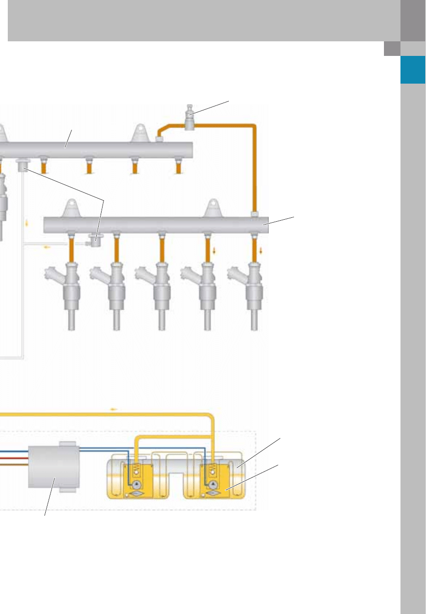
23
376_027
Fuel distributor (rail) 1
to the injectors
of cylinders 6-10
N84-N86, N299, N300
Injectors
of cylinders 1-5
N30-N33, N83
Fuel pressure sender G247
Fuel distributor (rail) 2
Pressure limiting valve (136 bar)
Fuel tank
Fuel pump (pre-supply pump) G6
Fuel pump control unit J538
24
376_022
376_031
5.2 litre V10 FSI engine
High-pressure fuel circuit
The FSI high-pressure injection system is also
employed in the V10 engine.
Central elements of the fuel system are two demand
controlled single-piston high-pressure pumps, each
of which is driven by a double cam on each intake
camshaft.
The pump is regulated according to demand by an
integral electrical quantity control valve.
The necessary max. fuel pre-supply pressure of
6 bar in the return system is provided by a demand-
controlled fuel pump integrated in the fuel tank.
To reduce fuel pressure pulsation, the pumps are
connected on the high-pressure side via the two
rails. In addition, high-pressure fuel feed is
configured in such a way that both pumps do not
compress the fuel simultaneously, but in a
staggered fashion.
The solenoid controlled high-pressure injectors are
operated at approx. 65 volts via capacitors in the
engine control units.
They are configured as single-hole tumble valves
having an injection angle (bend angle) of 7.5°.
The injection jet is designed to minimise cylinder
wall wetting.
In addition, the fuel evaporating in the combustion
chamber extracts heat from the cylinders which
results in a reduced knock sensitivity and a higher
charge density than in the MPI combustion process.
The FSI combustion process thereby permits a
compression ratio of 12.5 : 1.
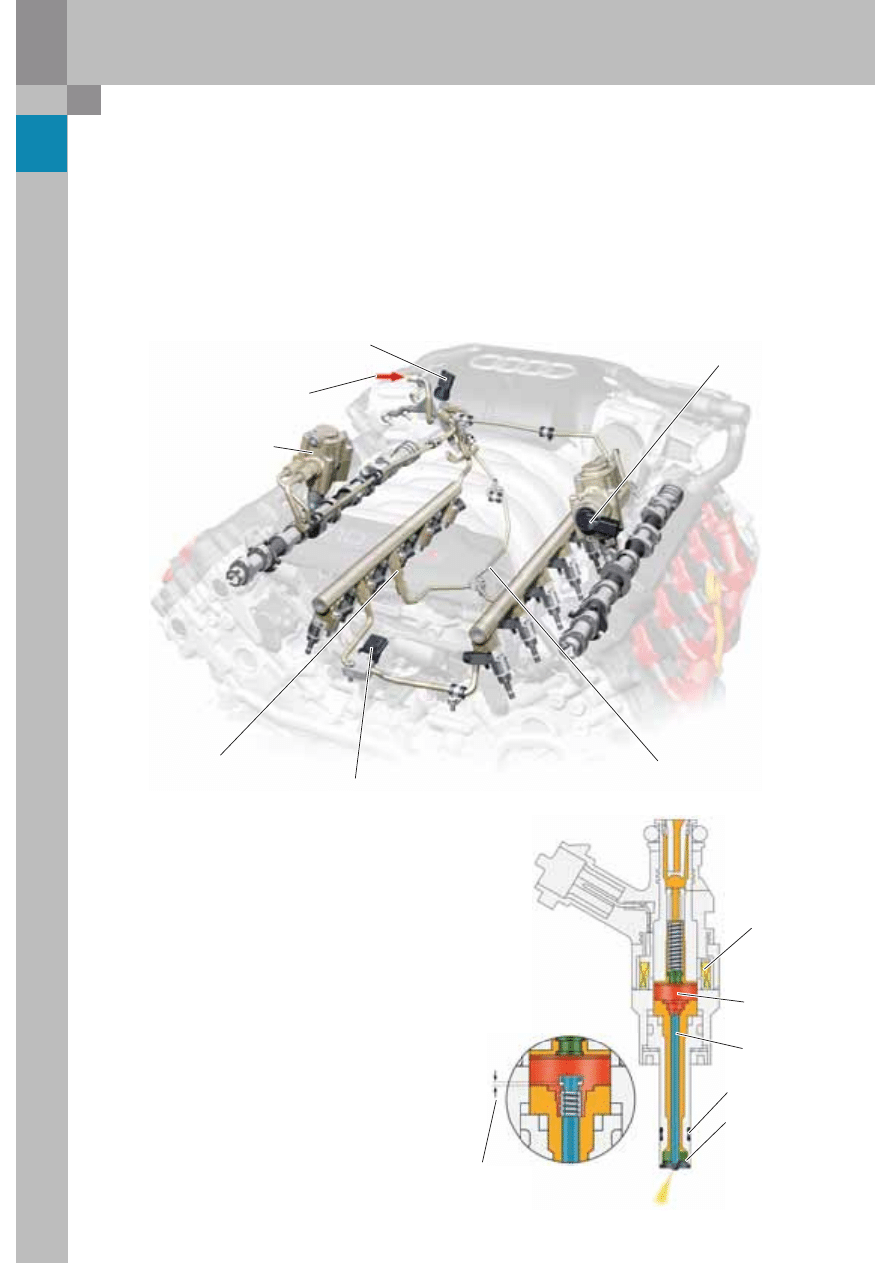
Fuel supply from tank
High pressure pump 2 with
fuel metering valve 2 N402
Fuel pressure sender,
low pressure G410
Pressure limiting valve
up to 136 bar
Fuel pressure sender G247
Leakage line
High pressure pump 1 with
fuel metering valve N290
Magnetic coil
Armature
Injector pintle
Teflon sealing
ring
Single-hole
swirl plates
Armature clearance
4/100 mm
25
376_023
376_028
376_029
376_030
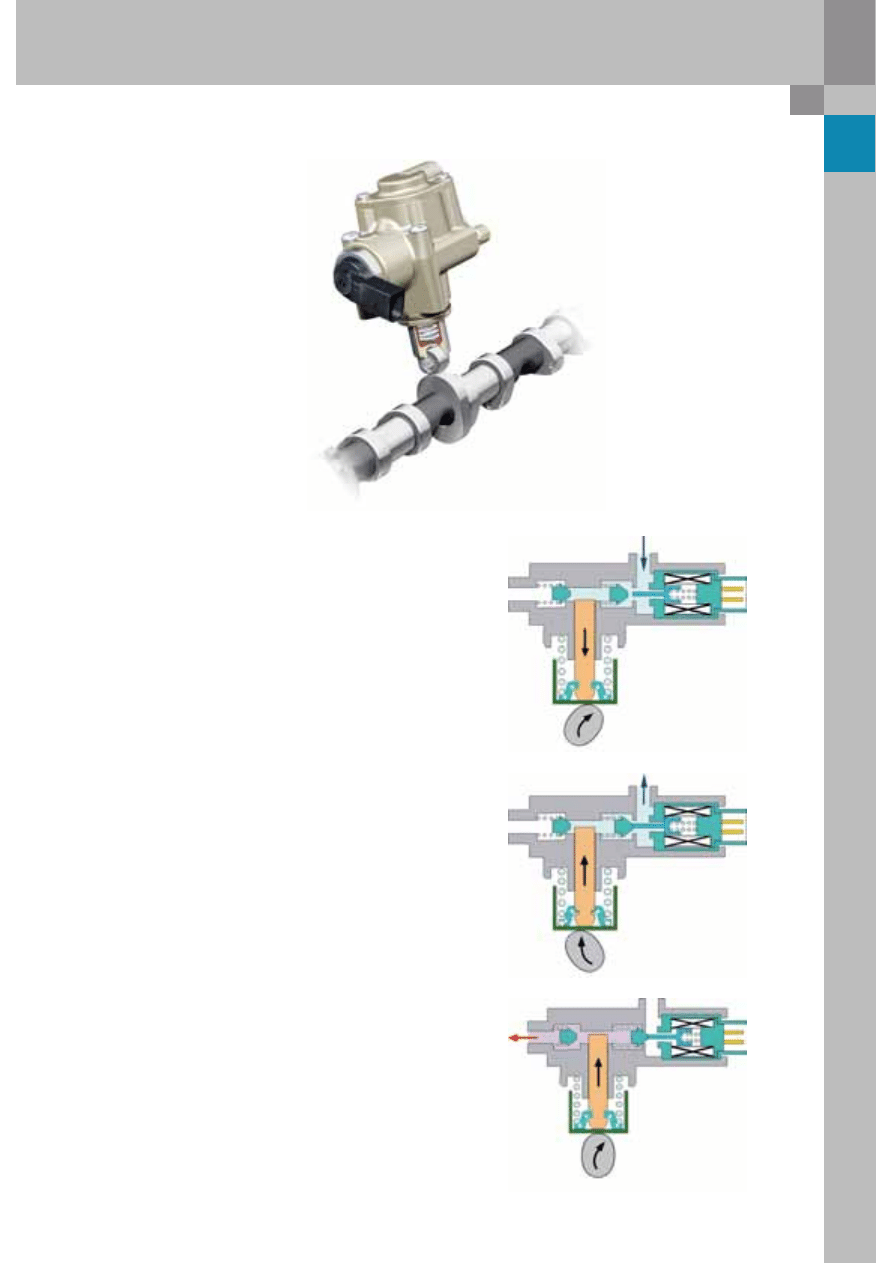
Pump functions
Suction stroke
The shape of the cam and the force of the piston
spring move the pump piston downwards.
The increase in space inside the pump provides
additional fuel flow. The low pressure valve is held
open by the quantity control valve.
The quantity control valve is deenergised.
Working stroke
The cam moves the pump piston upwards.
Pressure cannot be developed yet because the
quantity control valve is deenergised.
It prevents the low pressure intake valve from
closing.
Compression stroke
The engine control unit now energises the quantity
control valve. The solenoid armature is actuated.
The pressure inside the pump presses the low
pressure intake valve down into its seat.
When the pressure inside the pump exceeds the rail
pressure, the non-return valve opens and fuel is
admitted to the rail.
High-pressure fuel pump with fuel metering valve N290/N402
26
5.2 litre V10 FSI engine
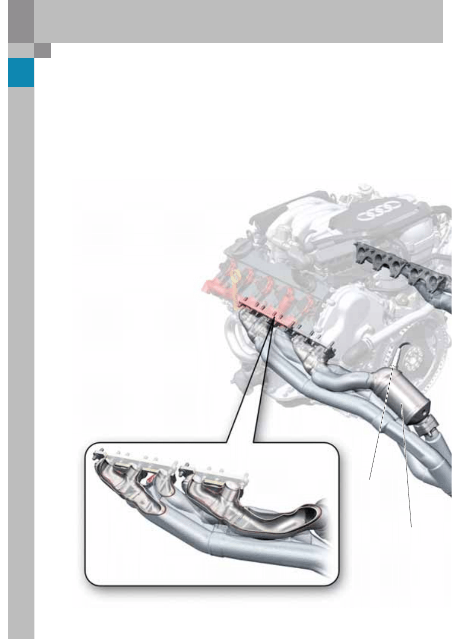
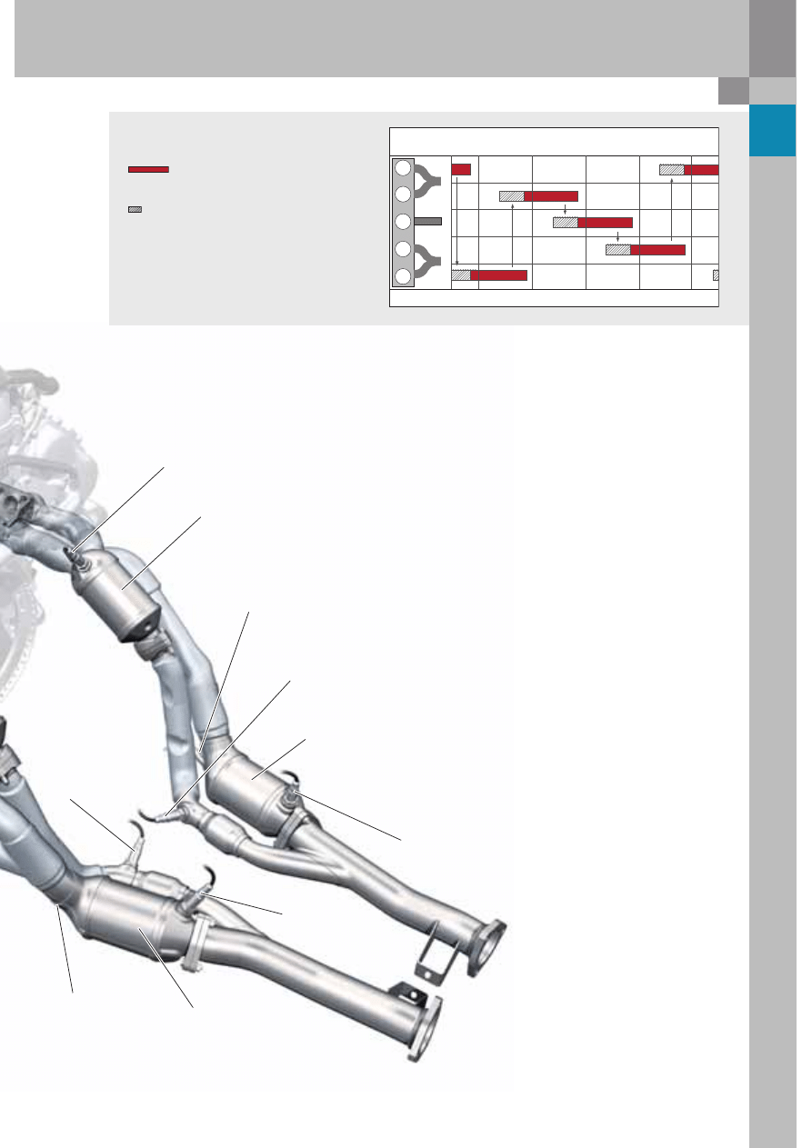
Exhaust system
Exhaust manifold
A V10 engine, in which the cylinders are opposed
at 90°, puts the same demands on the e xhaust-side
charge cycle components as a five-cylinder in-line
engine.
Each bank of cylinders is fired at a uniform firing
interval of 144°, which, with exhaust opening
periods of 210°, leads to a partial overlap between
the exhaust phases.
In the worst case, the exhaust pulse of a cylinder
can cause reverse pulsation of expelled exhaust
gases in the still-open exhaust port of a different
cylinder.
This will result in a higher residual gas content in
the cylinder and corresponding mean pressure
losses in the combustion process due to insufficient
fresh gas charging.
Oxygen sensor 4
G286
Bank 2
Catalytic converter
for cylinders 9-10
Air-gap insulated shell manifolds
in a 2-1-2 configuration per cylinder bank
27
376_020
This phenomenon of exhaust-gas flow pulsation is
counteracted by separating the individual exhaust
lines in the manifold for as long as possible.
A 5-in-1 manifold would be the obvious choice of
configuration, but requires a great deal of design
space. Furthermore, due to its large surface area and
the resulting thermal inertia, this configuration has
drawbacks in terms of emission control during the
warm-up phase (cat heating).
The chosen manifold configuration comprises three
exhaust lines whereby, in accordance with the firing
order (bank 1: 1-5-2-3-4 or bank 2: 6-10-7-8-9) the two
outer cylinders are combined due to their non-critical
firing intervals and the middle cylinder is separate.
The primary length of the middle cylinder exhaust
duct is over 650 mm.
The exhaust gases are treated by four 600-cell
ceramic catalytic converters working in combination
with a vacuum controlled secondary air system.
Due to the 2-1-2 exhaust configuration into two
exhaust pipes, the catalytic converter assigned to
the front three cylinders has a capacity of 0.76 litres,
while the exhaust gases from the two rear cylinders
are treated by a single catalytic converter with a
capacity of 0.62 l.
1
2
3
4
5
Exhaust valve open
Overlap
Exhaust opening periods
TDC1
720°/0°
TDC5
144°
TDC2
288°
TDC3
432°
TDC4
576°
Oxygen sensor G39
bank 1
Catalytic converter
for cylinders 4-5
Oxygen sensor 2 G108
bank 1
Catalytic converter
for cylinders 1-2-3
Oxygen 2 sensor after
catalytic converter G131
bank 1
Oxygen sensor 4 after
catalytic converter G288
bank 2
Catalytic converter
for cylinders 6-7-8
Oxygen sensor 3
after catalytic
converter G287
bank 2
Oxygen sensor after
catalytic converter G130
bank 1
Oxygen sensor 4 G286
bank 2
28
5.2 litre V10 FSI engine
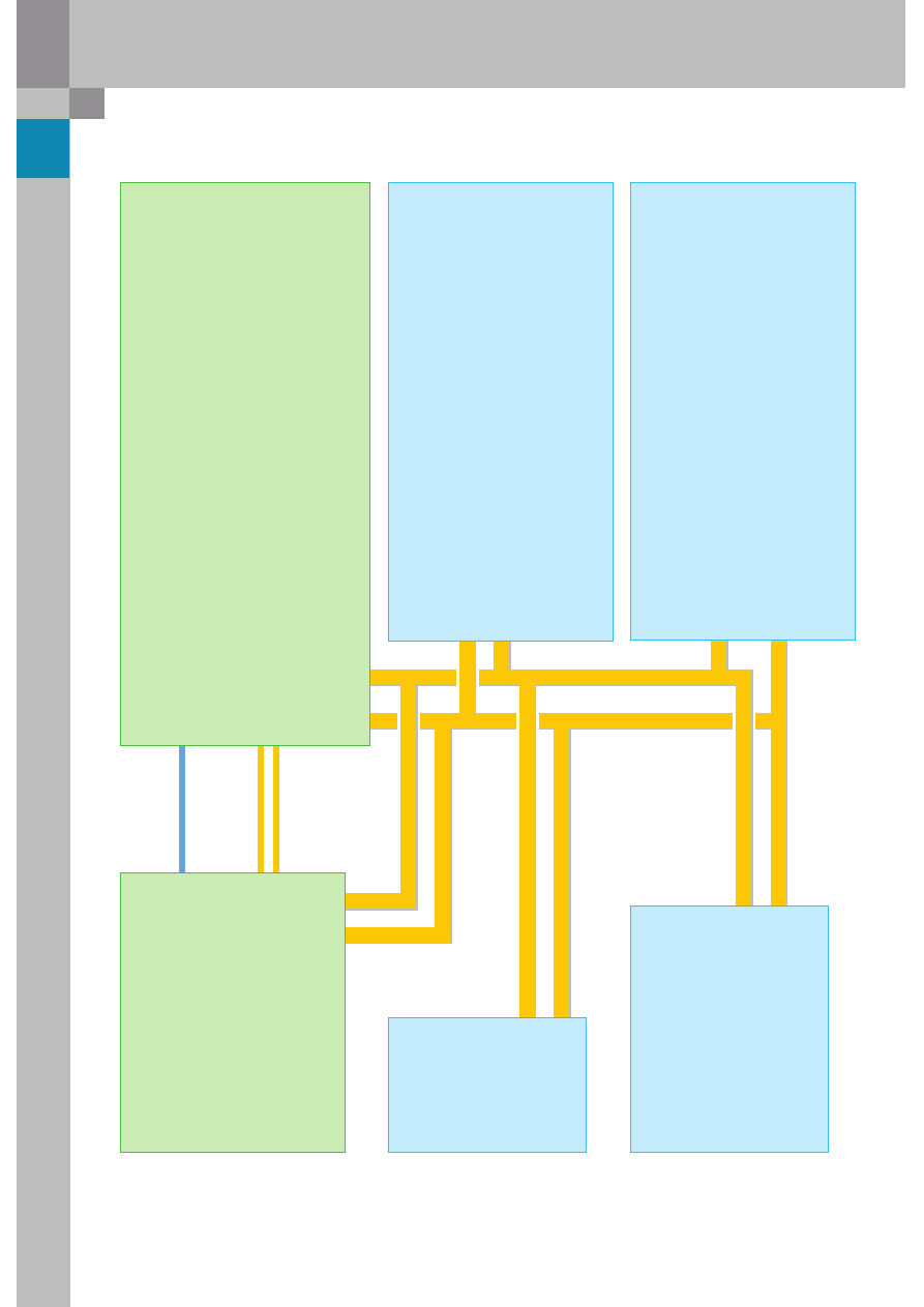
System overview (Bosch MED 9.1) in the Audi S8
Sensors
Air mass meter G70
Intake air temperature sensor G42
Accelerator pedal position sender G79
Accelerator pedal position sender 2 G185
Engine speed sender G28
Fuel pressure sender G247
Hall sender G40
Hall sender 3 G300
Fuel pressure sender, low pressure G410
Brake servo pressure sensor G294
Throttle valve module J338
Angle senders 1+2 for throttle-valve drive
with electric power control G187, G188
Lambda probe G39
Lambda probe after catalytic converter G130
Oxygen sensor 2 G108
Oxygen sensor 2 after catalytic converter G131
Brake light switch F
Brake pedal switch F47
Hall sender 2 G163
Hall sender 4 G301
Knock sensors 1+2 G61, G66
Coolant temperature sender G62
Intake manifold flap potentiometer G336
Auxiliary signals:
Cruise control system on/off
P/N signal
Terminal 50
Wake up door contact from convenience
system central control unit J393
Oxygen sensor 3 G285
Oxygen sensor 3 after catalytic converter G287
Oxygen sensor 4 G286
Oxygen sensor 4 after catalytic converter G288
Intake manifold flap 2 potentiometer G512
Knock sensors 3+4 G198, G199
Auxiliary signals:
Wake up door contact from
convenience system central control unit J393
CAN data bus
Powertrain
Engine control unit J623
(MSE)
Engine control unit 2 J624
(slave)
Air mass meter 2 G246
Throttle valve module 2 J544
Angle senders 1+2 for throttle valve
drive 2 G297, G298
29
376_032
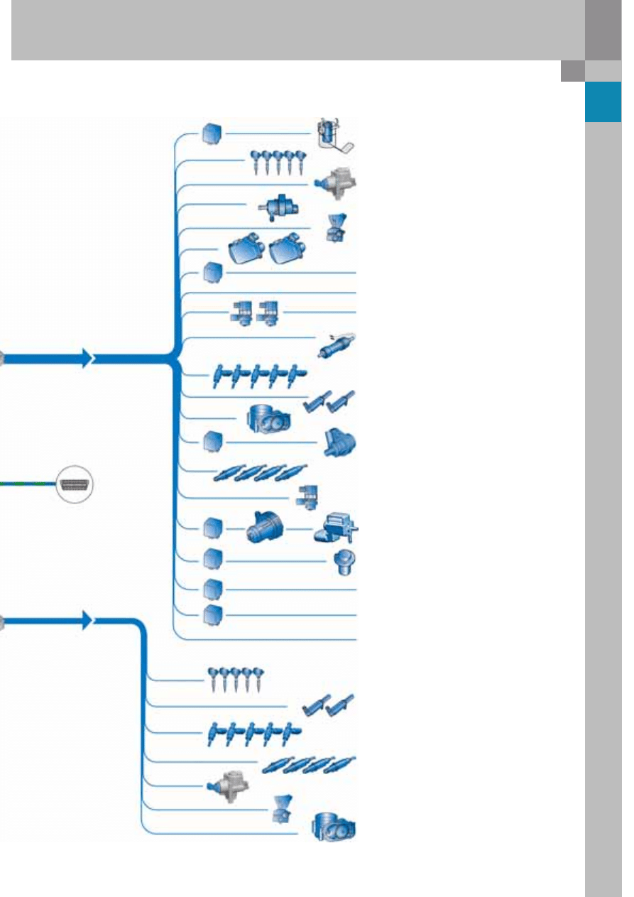
Actuators
Diagnostic
port
Fuel pump control unit J538
Fuel pump (pre-supply pump) G6
Injectors, cylinders 1-5
N30–N33, N83
Exhaust flap 1 valve N321
Exhaust flap 2 valve N322
Ignition coils N70, N127, N291, N292, N323
Cylinders 1–5
Activated charcoal filter solenoid valve 1 N80
Fuel metering valve N290
Throttle-valve drive for electric power control G186
Secondary air pump relay J299
Secondary air pump motor V101
Secondary air inlet valve N112
Auxiliary signals:
Engine speed
Radiator fan control units J293 and J671
Lambda probe 3 heater Z62
Lambda probe heater 3, after catalytic converter Z64
Lambda probe 4 heater Z63
Lambda probe 4 heater, after catalytic converter Z65
Fuel metering valve 2 N402
Throttle valve drive 2 G296
Electro/hydraulic engine mounting solenoid valve,
right N145
Inlet camshaft timing adjustment valve 1 N205
Exhaust camshaft timing adjustment valve 1 N318
Continued coolant circulation relay J151
Coolant run-on pump V51
Lambda probe 1 heater Z19
Lambda probe 1 heating, after catalytic converter Z29
Lambda probe 2 heater Z28
Lambda probe 2 heater, after catalytic converter Z30
Variable intake manifold change-over valve N335
Brake servo relay J569
Vacuum pump for brakes V192
Ignition coils N324–N328
Cylinders 6–10
Inlet camshaft timing adjustment valve 2 N208
Exhaust camshaft timing adjustment valve 2 N319
Injectors, cylinders 6-10
N84–N86, N299, N300
Electro/hydraulic engine mounting solenoid valve,
left N144
Intake manifold flap motor V157
Variable intake manifold motor V183
Fuel system diagnostic pump (USA) V144
Engine component current supply relay J757
Motronic current supply relay J271
Starter motor relay J53
Starter motor relay 2 J695
Mapped-controlled engine cooling thermostat F265
30
5.2 litre V10 FSI engine
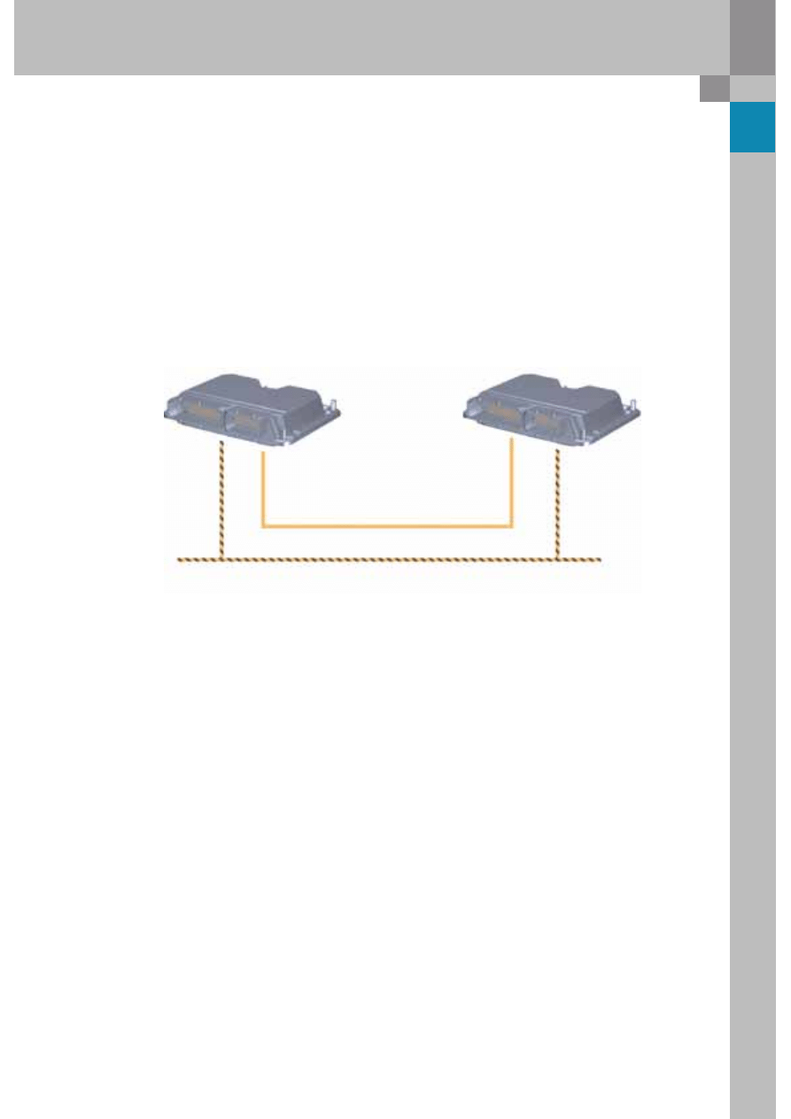
CAN data bus interfaces
CAN High
CAN Low
CAN 2
Low
CAN 2
High
Engine control unit 2 (slave) J624
Utilises the signals from
CAN 1 (powertrain CAN bus) and
CAN 2 (private CAN) to calculate
the activation of the actuators of
cylinder bank 2 (left bank) (refer
to System overview).
ABS control unit J104
TCS request
EBC request
ABS request
EDL intervention
ESP intervention
ESP brake light switch
Rough road suppression feature
ABS in diagnostics
Active brake servo
Road speed signal
TCS intervention torque
EBC intervention torque
TCS lamp activation
Lateral acceleration
Wheel speeds
Engine control unit (master) J623
Idle information
Accelerator pedal angle
Engine torque
Engine speed
Coolant temperature
Brake light switch information
Cruise control system status
Throttle valve angle
Intake air temperature
OBD2 lamp
"Hot" warning lamp
Air conditioner compressor "OFF" or
Power reduction
Starter control (automatic start)
Oil temperature
Steering angle sender G85
Steering wheel angle and
steering angle speed (is used
for idle speed regulation and
calculating the engine torque
according to the power
demand of the power steering
system)
Control unit with display in dash
panel insert J285
Light, rear
Steering column electronics
control unit J527:
All relevant messages form the
cruise control system
Sport switch
Climatronic control unit J255:
All signals which necessitate an
engine speed adjustment due to
load demands.
Control unit with display in dash
panel insert J285:
- Information from fuel tank
- Oil temperature
- Ambient temperature
- Time not in use
- Mileage (km)
- Information from oil level and
oil temperature sender G266
Airbag control unit J234
Impact intensity
Fuel shut-off
Discrete
line
31
376_043
Communication between the master/
slave control units
The engine control unit (MSE) J623 calculates and
controls the signals from the actuators for cylinder
bank 1.
Most sensors are connected to the engine control
unit (refer to System overview, page 28/29). Both
control units are connected to the CAN data bus.
The slave control unit functions as a receiver only.
The load signals required for calculation and control
of the signals for the cylinder bank 2 actuators are
transmitted across the private bus.
The slave control unit performs the task of misfire
detection for all ten cylinders. It also processes the
signal from engine speed sender G28.
The master and slave control units are identical in
design and have the same part number. A voltage
code in the control unit determines whether the
control unit is working as a master or as a slave.
If a positive signal is present at the encoding pin,
the control unit assumes the master function.
Control unit 1 - master
Control unit 2 - slave
Private bus CAN 2
CAN data bus
Injection of the metered fuel mass commences
during the compression stroke phase and ends
shortly before the firing point.
After end of start phase - HOSP = homogeneous split
Application:
– Heating of the pre-catalysts to 300 °C in
approx. 12 seconds; lambda value 1.05
– Intake manifold flap position: closed
– Throttle valve position: wide open
Injection:
– First injection approx. 300° before ignition TDC
– Second injection with small amount of fuel,
approx. 60° before ignition TDC - firing ignition
timing is retarded
– Mixture combusts very late
– Exhaust valve is already open
As a result, the catalytic converter reaches its
operating temperature very quickly.
Normal operation homogeneous carburetion
(lambda 1) with intake manifold flap open or closed
(map-dependent)
Compared to the low pressure start, homogenisation
is greatly improved and HC emissions are reduced
by utilising the heat of compression for carburetion
purposes.
With one close-coupled catalytic converter and one downstream catalytic converter to be heated per cylinder
bank, the engine runs in individual-cylinder lambda control mode at start-up. This means that the metered fuel
and secondary air mass flows between the individual cylinders are varied, firstly, to heat the downstream
catalytic converters with a rich air-fuel mixture. On the other hand, the close-coupled catalytic converters must
not be allowed to overheat during secondary operation. For this reason, the air-fuel mixture is set to a leaner
value.
Operating modes
Start phase - high pressure stratified charge start

376
Vorsprung durch Technik
www.audi.co.uk
All rights reserved. Technical
specifications subject to
change without notice.
Copyright
AUDI AG
N/VK-35
Service.training@audi.de
Fax +49-841/89-36367
AUDI AG
D-74172 Neckarsulm
Technical status: 06/06
Printed in Germany
A06.5S00.22.20
Wyszukiwarka
Podobne podstrony:
Self Study Programme 388 4 2L V8 4V FSI engine
Self Study Programme 279 2 0L 110kw with petrol direct injection FSI
Self Study Programme 189 2 3L petrol engine in the LT 97
Self Study Programme 351 Common rail fuel injection system fitted in the 3 0l V6 TDI engine
Self Study Programme 365 4 2L V8 with common rail
Self Study Programme 431 Audi RS 6
Self Study Programme 17 Octavia convenience electronic system
Self Study Programme 396 Lane change assist
Self Study Programme 276 Phaeton automatic proximity control
Self Study Programme 280 Phaeton auxiliary heater top c and top z
Self Study Programme 288 Audi A8 03 distributed functions
Self Study Programme 398 Audi lane assist
Case Study of Industrial Espionage Through Social Engineering
Extreme Self Care Program
19 Audi A6 1 9 litre turbo diesel engine (81 kW, 4 cylinder), engine codes AFN
ASM based Modelling of Self Replicating Programs
program studiow v10 1 1
An experimental study on the development of a b type Stirling engine
więcej podobnych podstron