
4408-XXX
Lexmark™ X6100 Series All-In-
One
Lexmark and Lexmark with diamond
design are trademarks of Lexmark
International, Inc., registered in the
United States and/or other countries.
• Index

Edition: March 24, 2006
The following paragraph does not apply to any country where such provisions are
inconsistent with local law
: LEXMARK INTERNATIONAL, INC. PROVIDES THIS
PUBLICATION “AS IS” WITHOUT WARRANTY OF ANY KIND, EITHER EXPRESS OR
IMPLIED, INCLUDING, BUT NOT LIMITED TO, THE IMPLIED WARRANTIES OF
MERCHANTABILITY OR FITNESS FOR A PARTICULAR PURPOSE. Some states do
not allow disclaimer of express or implied warranties in certain transactions; therefore, this
statement may not apply to you.
This publication could include technical inaccuracies or typographical errors. Changes are
periodically made to the information herein; these changes will be incorporated in later
editions. Improvements or changes in the products or the programs described may be
made at any time.
Comments may be addressed to Lexmark International, Inc., Department D22A/032-2,
740 West New Circle Road, Lexington, Kentucky 40550, U.S.A or e-mail at
ServiceInfoAndTraining@Lexmark.com. Lexmark may use or distribute any of the
information you supply in any way it believes appropriate without incurring any obligation
to you.
Lexmark, Lexmark with diamond design, Color Jetprinter, and ColorFine are trademarks
of Lexmark International, Inc., registered in the United States and/or other countries.
Other trademarks are the property of their respective owners.
© 2003 Lexmark International, Inc.
All rights reserved.
UNITED STATES GOVERNMENT RIGHTS
This software and any accompanying documentation provided under this agreement are
commercial computer software and documentation developed exclusively at private
expense.
4408-XXX
U.S.A. P/N: 12G9253
Japanese P/N: 12G9254

Table of contents
iii
4408-XXX
Table of contents
Safety information. . . . . . . . . . . . . . . . . . . . . . . . . . . . . . . . . . . . . . . . v
Preface . . . . . . . . . . . . . . . . . . . . . . . . . . . . . . . . . . . . . . . . . . . . . . . . . x
. . . . . . . . . . . . . . . . . . . . . . . . . . . . . . . . . . . . . . . . . . . . . . . x
. . . . . . . . . . . . . . . . . . . . . . . . . . . . . . . . . . . . 1-1
. . . . . . . . . . . . . . . . . . . . . . . . . . . . . . . . . . . . . 1-1
. . . . . . . . . . . . . . . . . . . . . . . . . . . . . . . . . . . . . . . 1-1
. . . . . . . . . . . . . . . . . . . . . . . . . . . . . . . . . . . 1-2
. . . . . . . . . . . . . . . . . . . . . . . . . . . . . . . . . . . . . . . . . . 1-4
. . . . . . . . . . . . . . . . . . . . . . . . . . . . . . . . . . . 1-5
. . . . . . . . . . . . . . . . . . . . . . . . . . . . . . . . . . . . . . . . 1-6
. . . . . . . . . . . . . . . . . . . . . . . . . . . . . . . . . 2-1
. . . . . . . . . . . . . . . . . . . . . . . . . . . . . . . . . . . . . . . . . . . . . . . . . 2-1
Power-On Self Test (POST) sequence
. . . . . . . . . . . . . . . . . . . . 2-1
. . . . . . . . . . . . . . . . . . . . . . . . . . . . . . . . . . 2-2
. . . . . . . . . . . . . . . . . . . . . . . . . . . . . . . . . . . . . . 2-3
. . . . . . . . . . . . . . . . . . . . . . . . . . . . . . . . . . . . . . . . . 2-6
Carrier Transport service check
. . . . . . . . . . . . . . . . . . . . . . . . . . 2-6
CCD Module Assembly service check
. . . . . . . . . . . . . . . . . . . . . 2-8
Maintenance Station service check
. . . . . . . . . . . . . . . . . . . . . . . 2-9
. . . . . . . . . . . . . . . . . . . . . . . . . . . . . 2-10
. . . . . . . . . . . . . . . . . . . . . . . . . . . . . 2-12
. . . . . . . . . . . . . . . . . . . . . . . . . . . . . . . . . 2-13
. . . . . . . . . . . . . . . . . . . . . . . . . . . . . 2-14
Scan/Copy Quality service check
. . . . . . . . . . . . . . . . . . . . . . . . 2-16
. . . . . . . . . . . . . . . . . . . . . . . . . . . . . . . . . . . . . . . . 3-1
. . . . . . . . . . . . . . . . . . . . . . . . . . . . . . . . . . . . . . . . . . . . . 3-1
. . . . . . . . . . . . . . . . . . . . . . . . . . . . . . . . . . . . . 4-1
. . . . . . . . . . . . . . . . . . . . . . . . . . . . . . 4-1
. . . . . . . . . . . . . . . . . . . . . . . . . . . . . . . . . . . . . . . . . . . 4-2

iv
Service Manual
4408-XXX
. . . . . . . . . . . . . . . . . . . . . . . . . . . . . . . . . . . . .4-2
. . . . . . . . . . . . . . . . . . . . . . . . . . . . . . . .4-2
. . . . . . . . . . . . . . . . . . . . . . . . . . . . . .4-3
. . . . . . . . . . . . . . . . . . . . . . . . . . . . . . . . . . . . . . . . .4-4
. . . . . . . . . . . . . . . . . . . . . . . . . . . . . . . .4-5
. . . . . . . . . . . . . . . . . . . . . . . . . . . . . . . . . . . . . . .4-6
. . . . . . . . . . . . . . . . . . . . . . . . . . . . . . . . . . . . . .4-7
. . . . . . . . . . . . . . . . . . . . . . . . . . . .4-9
. . . . . . . . . . . . . . . . . . . . . . . . . . . . . . . . . . . .4-11
. . . . . . . . . . . . . . . . . . . . . . . . . . . . . . . . . .4-12
. . . . . . . . . . . . . . . . . . . . . . . . . .4-12
Scanner and ADF assembly removal
. . . . . . . . . . . . . . . . . . . . .4-12
. . . . . . . . . . . . . . . . . . . . . . . . . . . . . . . .4-15
. . . . . . . . . . . . . . . . . . . . . . . . . . . . . . . . . . . .5-1
. . . . . . . . . . . . . . . . . . . . . . . . . . . . . . . . .6-1
. . . . . . . . . . . . . . . . . . . . . . . . . . . . . . . . .6-1
. . . . . . . . . . . . . . . . . . . . . . . . . . . . . . . . . . . . . . . . . .7-1
. . . . . . . . . . . . . . . . . . . . . . . . . . . . . . . . . . . . .7-2
Assembly 2: Paper feed, frame, and carrier transport
. . . . . . . . . . . .7-6
. . . . . . . . . . . . . . . . . . . . . . . . . . . . . . . . . . .7-8
Index . . . . . . . . . . . . . . . . . . . . . . . . . . . . . . . . . . . . . . . . . . . . . . . . X-1

Safety information
v
4408-XXX
Safety information
•
The safety of this product is based on testing and approvals of
the original design and specific components. The manufacturer
is not responsible for safety in the event of use of unauthorized
replacement parts.
•
The maintenance information for this product has been
prepared for use by a professional service person and is not
intended to be used by others.
•
There may be an increased risk of electric shock and personal
injury during disassembly and servicing of this product.
Professional service personnel should understand this and take
necessary precautions.
Consignes de Sécurité
•
La sécurité de ce produit repose sur des tests et des
agréations portant sur sa conception d'origine et sur des
composants particuliers. Le fabricant n'assume aucune
responsabilité concernant la sécurité en cas d'utilisation de
pièces de rechange non agréées.
•
Les consignes d'entretien et de réparation de ce produit
s'adressent uniquement à un personnel de maintenance
qualifié.
•
Le démontage et l'entretien de ce produit pouvant présenter
certains risques électriques, le personnel d'entretien qualifié
devra prendre toutes les précautions nécessaires.

vi
Service Manual
4408-XXX
Norme di sicurezza
•
La sicurezza del prodotto si basa sui test e sull'approvazione
del progetto originale e dei componenti specifici. Il produttore
non è responsabile per la sicurezza in caso di sostituzione non
autorizzata delle parti.
•
Le informazioni riguardanti la manutenzione di questo prodotto
sono indirizzate soltanto al personale di assistenza autorizzato.
•
Durante lo smontaggio e la manutenzione di questo prodotto,
il rischio di subire scosse elettriche e danni alla persona è più
elevato. Il personale di assistenza autorizzato, deve, quindi,
adottare le precauzioni necessarie.
Sicherheitshinweise
•
Die Sicherheit dieses Produkts basiert auf Tests und
Zulassungen des ursprünglichen Modells und bestimmter
Bauteile. Bei Verwendung nicht genehmigter Ersatzteile wird
vom Hersteller keine Verantwortung oder Haftung für die
Sicherheit übernommen.
•
Die Wartungsinformationen für dieses Produkt sind
ausschließlich für die Verwendung durch einen
Wartungsfachmann bestimmt.
•
Während des Auseinandernehmens und der Wartung des
Geräts besteht ein zusätzliches Risiko eines elektrischen
Schlags und körperlicher Verletzung. Das zuständige
Fachpersonal sollte entsprechende Vorsichtsmaßnahmen
treffen.

Safety information
vii
4408-XXX
Pautas de Seguridad
•
La seguridad de este producto se basa en pruebas y
aprobaciones del diseño original y componentes específicos.
El fabricante no es responsable de la seguridad en caso de uso
de piezas de repuesto no autorizadas.
•
La información sobre el mantenimiento de este producto está
dirigida exclusivamente al personal cualificado de
mantenimiento.
•
Existe mayor riesgo de descarga eléctrica y de daños
personales durante el desmontaje y la reparación de la
máquina. El personal cualificado debe ser consciente de este
peligro y tomar las precauciones necesarias.
Informações de Segurança
•
A segurança deste produto baseia-se em testes e aprovações
do modelo original e de componentes específicos. O fabricante
não é responsável pela segunrança, no caso de uso de peças
de substituição não autorizadas.
•
As informações de segurança relativas a este produto
destinam-se a profissionais destes serviços e não devem ser
utilizadas por outras pessoas.
•
Risco de choques eléctricos e ferimentos graves durante a
desmontagem e manutenção deste produto. Os profissionais
destes serviços devem estar avisados deste facto e tomar os
cuidados necessários.
viii
Service Manual
4408-XXX
Informació de Seguretat
•
La seguretat d'aquest producte es basa en l'avaluació i
aprovació del disseny original i els components específics.
El fabricant no es fa responsable de les qüestions de
seguretat si s'utilitzen peces de recanvi no autoritzades.
•
La informació pel manteniment d’aquest producte està
orientada exclusivament a professionals i no està destinada
a ningú que no ho sigui.
•
El risc de xoc elèctric i de danys personals pot augmentar
durant el procés de desmuntatge i de servei d’aquest producte.
El personal professional ha d’estar-ne assabentat i prendre
les mesures convenients.
Safety information
ix
4408-XXX

x
Service Manual
4408-XXX
Preface
This manual contains maintenance procedures for service
personnel. It is divided into the following chapters:
1.
General information
contains a general description of the
printer and the maintenance approach used to repair it. Special
tools and test equipment are listed in this chapter, as well as
general environmental and safety instructions.
2.
Diagnostic information
contains an error indicator table,
symptom tables, and service checks used to isolate failing field
replaceable units (FRUs).
3.
Diagnostic aids
contains tests and checks used to locate or
repeat symptoms of printer problems.
4.
Repair information
provides instructions for making printer
adjustments and removing and installing FRUs.
5.
Connector locations
uses illustrations to identify the connector
locations and test points on the printer.
6.
Preventive maintenance
contains the lubrication specifications
and recommendations to prevent problems.
7.
Parts catalog
contains illustrations and part numbers for
individual FRUs.
Definitions
CAUTION:
A caution identifies something that might cause a
servicer harm.
Warning:
A warning identifies something that might damage the
printer hardware or software.
Note:
A note provides additional information.

General information
1-1
4408-XXX
1. General information
The Lexmark™ X6170 4408-K01/AK1 and X6150 4408-K02/AK2
machines feature an electro-mechanical color scanner, printer,
copier, and fax that creates characters and graphics by composing
programmed patterns of ink dots using a printhead and liquid ink.
The printhead uses small heater plates and nozzles to control ink
flow and the formation of characters on the print media. The
printhead assembly and ink supply are combined into a single-unit,
print cartridge available as a customer replaceable supply item. Dual
printheads provide color and true black printing without changing
printheads. The number and size of inkjets or nozzles, in the
printhead, determines the overall quality and capability of the printer.
The black cartridge has a total of 208 nozzles and installs on the left.
The color cartridge has a total of 192 nozzles and installs on the
right. The printer is capable of printing in two directions from either
cartridge.
Power consumption
•
2.55 Watts - Sleep
•
3.107 Watts - Printing
•
6.64 Watts - Idle
Machine types
4408-K01/AK1
4408-K02/AK2

1-2
Service Manual
4408-XXX
Scanner specifications
Scanner Type
Flatbed, CCD
Scan Modes
True Color:
48 Bit Internal (68.7 billion colors)
24 Bit External (16.7 million colors)
Gray Mode:
12 Bit Internal (4,096 shades of
gray)
8 Bit External (256 shades of gray)
Text/Line Art:
1 Bit Per Pixel
Scan Method
One Pass Scanning
Scan Area
8.5 X 11.7 inches
216 X 292 mm
Scan Resolution
Flatbed Scanning:
-Optical: 1200 (H) x 4800 ppi (V)
-Interpolated: 19,200 x 19,200 ppi
ADF Scanning (4408-K01/AK1) only
-Optical: 600 (H) x 300 ppi (V)
Resolution/Quality
(Applicable when operating via
standalone mode)
Selectable via Contorl Panel
-Quick-
300 x 300 ppi Scan
600 x 300 dpi Print
-Normal-
300 x 600 ppi Scan
600 x 600 dpi Print
-Better-
600 x 600 ppi Scan
600 x 600 dpi Print
-Best-
600 x 600 ppi Scan
600 x 600 dpi Print
Notes:
1) Photo Mode = Best Mode
2) The number of printhead passes
will increase with the quality mode.

General information
1-3
4408-XXX
Resolution/Quality
(Applicable when operating via
Host)
Selectable via All-In-One GUI for
Color/Gray
-Quick-
75 x 75 ppi Scan
600 x 300 dpi Print
-Normal-
150 x 150 ppi Scan
600 x 600 dpi Print
-Better-
200 x 200 ppi Scan
1200 x 1200 dpi Print
-Best-
300 x 300 ppi Scan
2400 x 1200 dpi Print
Selectable via All-In-One GUI for
Black Copy
-Quick-
150 x 150 ppi Scan
600 x 300 dpi Print
-Normal-
300 x 300 ppi Scan
600 x 600 dpi Print
-Better-
600 x 600 ppi Scan
1200 x 1200 dpi Print
-Best-
600 x 1200 ppi Scan
2400 x 1200 dpi Print
1-4
Service Manual
4408-XXX
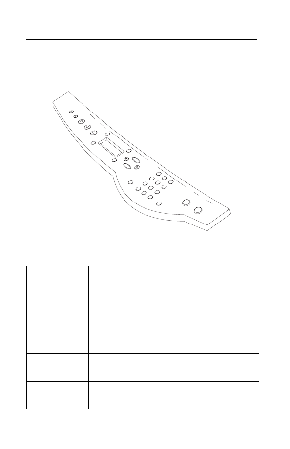
Control panel
Press:
To:
Number of
Copies
Select the number of copies.
Lighter/Darker
Lighten or darken a copy.
Reduce/Enlarge
Make the document smaller or larger.
Left arrow <
Right arrow>
Scroll through menu sub-categories.
Options
Scroll through the list of menu headings.
Select
Choose the displayed selection.
Quality
Choose normal, better, best, or quick copy setting.
Color Copy
Make a color copy.

General information
1-5
4408-XXX
Maintenance approach
The diagnostic information in this manual leads you to the correct
field replaceable unit (FRU) or part. Use the symptom index, service
checks, and diagnostic aids to determine the symptom and repair
the failure.
After you complete the repair, perform tests as needed to verify the
repair.
Black Copy
Make a black and white copy.
Scan
Scan after selecting a Scan To destination.
Stop/Clear
Cancel a scan, print, or copy job, or return to a menu
category from a menu sub-category.
Power
Turn the printer on or off.
Press:
To:

1-6
Service Manual
4408-XXX
Abbreviations
B/M
Bill of Material
CCD
Charge Coupled Device
EOF
End of Form
ESD
Electrostatic Discharge
FPC
Flat Printhead Cable
FRU
Field Replaceable Unit
HVPS
High Voltage Power Supply
LCD
Liquid Crystal Display
LVPS
Low Voltage Power Supply
OEM
Original Equipment Manufacturer
V ac
Volts alternating current
V dc
Volts direct current
ZIF
Zero Insertion Force

Diagnostic information
2-1
4408-XXX
2. Diagnostic information
Start
Use the symptom tables, service checks, and diagnostic aids in this
chapter, to determine the printer failure.
Power-On Self Test (POST) sequence
Press the
Power
button to turn machine on.
•
The Power, Copy, Scan, and Fax indicator lights turn on.
•
The Charge-Coupled Device (CCD) moves to the right, and
then to the left.
•
The paper feed motor runs then stops.
•
The carrier moves and then returns to the maintenance station.
•
The
Power
and
Copy
buttons stay on.
•
The following message is displayed on the LCD.
If your printer completes POST with no errors, go to the
, locate the symptom and take the indicated
action.
If your printer does not complete POST, locate the symptom in the
following table and take the indicated action.
Normal
PY
1
1

2-2
Service Manual
4408-XXX
POST symptom table
Symptom
Action
No Power, Copy,
Fax, or Scan
lights and no
motors run.
Go to the
“Power service check” on page 2-13
go to the
“Control panel problems” on page 2-3
.
Paper feed
gears do not
turn
Go to the
“Paper Feed service check” on page 2-10
.
Carrier does not
move
Go to the
“Carrier Transport service check” on
Carrier slams
side frame
Go to the
“Carrier Transport service check” on
CCD does not
move
Go to the
“Maintenance Station service check” on
CCD lamp does
not turn on
Go to the
“CCD Module Assembly service check” on
LCD displays
“Unlock
Scanner”
Go to the

Diagnostic information
2-3
4408-XXX
Symptom tables
Locate the symptom in the following tables and take the appropriate
action.
Carrier transport problems
Maintenance station problems
Control panel problems
Symptom
Action
• No carrier movement
• Slow carrier movement
• Carrier stops
• Carrier slams side frame
Go to the
.
Symptom
Action
Maintenance station:
• Fails to cap the printheads
• Fails to clean the printheads
Go to the
.
Symptom
Action
• Buttons do not work
• LCD does not display
Check control panel cable
connection at J4 on the system
board. Then run the
Self Test (POST) sequence” on
page 2-1
If the LED buttons or any lights fail,
check connection J4. If the problem
remains, replace the scanner
assembly. Go to the
ADF assembly removal” on
page 4-12
If the problem still exists, replace the
system board. Go to the
.

2-4
Service Manual
4408-XXX
Printer communication table
Scanner problems
Symptom
Action
• Not able to print Test Page
Check the USB cable and system
board cable connections. If okay,
replace system board. Go to the
“System board removal” on
page 4-15
Symptom
Action
• CCD does not move
• Lamp does not light
Go to the
• Control panel displays “Unlock
Scanner”
To unlock the scanner, press the
scanner lock located under the
scanner assembly.
• Scanned images are: faded, or
colors are dull, blurry or fuzzy.
Images are slanted or crooked
and the strait lines in the image
appear to be jagged or uneven.
• Blank copies
Go to the
.

Diagnostic information
2-5
4408-XXX
Paper feed problems
Power problems
Print quality problems
Symptom
Action
• Fails to pick paper
• Picks more than one sheet of
paper
• Picks paper but fails to feed
• Paper jams
• Paper fails to exit
• Noisy paper feed
Go to the
Envelopes fail to feed
Go to the
Paper skews
Go to the
Symptom
Action
No power in machine, motors do
not operate
Go to the
Symptom
Action
• Voids in characters
• Light print
• Prints off the page
• Fuzzy print
• Carrier moves but no print
• Printhead dries prematurely
• Colors print incorrectly
• Vertical alignment off
Go to the
• Ink smearing
• Vertical streaks on paper
• Print lines crowded
Go to the

2-6
Service Manual
4408-XXX
Service checks
Carrier Transport service check
FRU
Action
1
System Board
Carrier Transport
Motor
Check the transport carrier motor connector JP7. If
connected, check for approximately 30 volts on
pins 1 and 2 or at the wire connections located on
the rear of the transport carrier motor. If voltage is
incorrect, replace the system board. If voltage is
correct, check the motor for shorts. If motor needs
replacing, replace the print engine. Go to
2
Carrier Transport
Motor
Check the motor for binds, or loose motor pulley.
A noisy or chattering motor or a motor that fails to
turn can be caused by:
•
An open or short in the motor.
•
An open or short in the motor driver
on the system board.
•
A bind in the carrier transport
mechanism.
With the carrier transport motor cable (JP7)
disconnected from the system board, check for 0
to 10 ohms between the following pins on the
motor:
JP7-1 and JP7-2
If the readings are incorrect, replace the print
engine. Go to the
.
3
Carrier Guide Rod
Clean the carrier rod.
Note
: Lubricate the rod and the carrier rod bearing
surfaces with grease P/N 99A0394.

Diagnostic information
2-7
4408-XXX
4
Encoder Strip
Carrier Assembly
Check the encoder strip for proper installation.
Also, check it for wear, dirt, and grease.
Be sure all printhead connectors are fully seated.
Check the cables for damage.
If the encoder strip and all connections are okay,
but the carrier still slams the side frame, replace
the print engine. Go to the
.
5
Carrier Transport
Belt
Idler Pulley Parts
Carrier Frame
Check for worn, loose or broken parts. Check for
obstructions blocking carrier movement.
Check the carrier belt idler pulley mounting screw.
Loosen the screw and allow the tension spring to
take up any slack in the belt. Tighten the screw. If
the pulley mounting bracket has reached the stop,
replace the carrier assembly. Go to the
carrier belt tensioner screw (A).” on page 4-6
Lubricate carrier to carrier frame engagement with
grease P/N 99A0394.
6
Printhead Carrier
Assembly
Disconnect the printer and check the carrier
printhead connectors JP1 and JP2. If the
connections are good, remove the printhead
carrier and check the cable connection to the
home sensor board. If the problem remains,
replace the system board. Go to the
7
Maintenance
Station
A problem with the maintenance station can cause
carrier movement problems at the right margin. Go
to the
“Maintenance station removal” on
FRU
Action

2-8
Service Manual
4408-XXX
CCD Module Assembly service check
The CCD (charge-coupled device) Module does not move during
POST Test.
The CCD lamp does not come on when CCD module assembly
moves.
The CCD LCD displays “Unlock Scanner.”
FRU
Action
1
CCD Module Assembly
If CCD module does not move, go to
the
.
If lamp does not come on as CCD
module assembly is scanning or
moving, check connector (JP9) on
the system board. If connected and
the lamp still does not work, replace
the control panel scanner assembly.
If the problem persists, replace the
system board. Go to
more information.
To unlock scanner, press the red
lever down.
Note:
Unlock scanner before use.

Diagnostic information
2-9
4408-XXX
Maintenance Station service check
The maintenance station has three functions:
1. Wipes the printhead nozzles to clean them of dirt.
2. Provides a place for printheads to fire all nozzles, keeping them
clear prior to printing.
3. Seals the printhead when it is not being used to prevent the
nozzles from drying.
FRU
Action
1
Maintenance
Station Assembly
As the carrier moves to the left over the
maintenance station, a slot on the bottom of the
carrier engages a tab on the sled of the
maintenance station causing the cap to rise and
seal the printhead. Carrier movement to the right
uncaps the printhead. The wiper cleans the
printhead nozzles as the carrier leaves the
maintenance station. The wiper cleans the
printhead only when the carrier is moving to the
left. There should be no wiping action of the
printhead nozzles when the carrier is moving to
the right. After the cleaning operation is complete,
a tab on the maintenance station engages a tab on
the carrier, causing the wiper to lower.
Check the maintenance station for worn or broken
parts. Replace if needed. Go to the
.
Worn wipers cause degraded print quality just after
a maintenance cleaning. Check for loose or worn
wipers.
Worn caps cause the printhead nozzles to dry and
clog. Check for loose or worn caps.

2-10
Service Manual
4408-XXX
Paper Feed service check
If your machine does not have paper jam problems, continue with
the service check. If your machine does have a paper jam problem,
examine it for the following before you begin the service check:
•
Check the entire paper path for obstructions.
•
Be sure there is not too much paper in the sheet feeder.
•
Be sure the correct type of paper is being used.
•
Check for static in the paper.
FRU
Action
1
System Board
Run the
. Replace parts as
needed. To check the paper feed motor,
disconnect the paper feed connector JP5 and
check for approximately 5 ohms between pins:
1 and 2
3 and 4
If the reading is incorrect, replace the print engine.
Go to the
“Print engine removal” on page 4-12
If the reading is correct, replace the system board.
Go to the
.

Diagnostic information
2-11
4408-XXX
2
Paper Feed Motor
A noisy or chattering motor or a motor that fails to
turn, can be caused by:
• An open or short in the motor
• An open or short in the motor driver on the
system board
• A bind in the paper feed mechanism
With the paper feed motor cable JP5 disconnected
from the system board, check for approximately 5
ohms between the following pins on the motor:
1 and 2
3 and 4
If the readings are incorrect, replace the print
engine. Go to the
Although the paper feeds in a forward direction
only, the paper feed motor turns in two directions.
If the paper feed motor turns in one direction only,
replace the system board. Go to the
Binds in the paper feed motor or gear train can
cause intermittent false paper jam errors. Remove
the paper feed motor and check the shaft for binds.
Also check for a loose or worn motor gear.
3
Auto Sheet
Feeder Assembly
Check the pick roller for wear.
4
Mid Frame
Assembly
Check the following for wear:
• Small Feed rollers
• Large Feed roller
• Exit roller
• Star rollers
If the mid frame assembly needs to be replaced,
go to the
“Print engine removal” on page 4-12
and replace print engine.
5
End-of-Forms
Flag and Spring
Check for binds or damage.
FRU
Action

2-12
Service Manual
4408-XXX
Paper Path service check
Examine the machine for the following before you begin this service
check:
•
Check the entire paper path for obstructions.
•
Be sure the correct type of paper is being used.
•
Be sure the printer is installed on a flat surface.
Note:
If any of these items are damaged or defective, replace the
print engine. Go to
“Print engine removal” on page 4-12
FRU
Action
1
Large and Small
Feed Rollers
Check for wear and binds.
2
Small Feed Roller
Springs
Check for damage.
3
Auto Sheet
Feeder Assembly
Check the pick roller for wear.
4
Mid Frame Asm
Check the following for wear:
• Exit roller
• Star rollers
5
End-of-Forms
Flag
Check for binds or damage.

Diagnostic information
2-13
4408-XXX
Power service check
FRU
Action
1
External Power
Supply
Plug the external power supply into an outlet.
Check for + 30 V dc. If voltage is incorrect, replace
the power supply.
2
Printhead Cable
Paper Feed Motor
Carrier Transport
Motor
Control Panel
Unplug the printer. Check all connections and plug
in the printer. Look for a symptom change. Check
the failing part for shorts and replace as
necessary.
3
System Board
If the symptom has not changed, replace the
system board. Go to the
.

2-14
Service Manual
4408-XXX
Print Quality service check
FRU / Function
Action
1
Printhead
Cartridge
Be sure the machine contains good print
cartridges.
2
Color Printhead
Cartridge Cross
Contamination
Cross contamination of color inks results in
incorrect colors printed, as when green prints for
yellow, (when yellow and blue are mixed in the
printhead cartridge). This problem resolves quickly
as the printhead cartridge is used.
If cross contamination occurs, check the following:
• The maintenance station wiper for damage.
• The printhead nozzle plate was resealed with
tape.
3
Printhead Carrier
Assembly
Reseat the printhead cables in the system board
and check the following parts for wear or damage:
• Printhead Cartridge Latch
• Latch Spring
• Carrier
4
System Board
Printhead Carrier
Assembly
. Look for a
break in the diagonal line of the nozzle test
pattern. A broken line indicates one or more print
nozzles are not working. Run the test again to
verify the failure.
Check the gold-plated contacts on the end of the
printhead carrier cable for dirt, wear and damage.
Use only a clean dry cloth to clean the contacts.
If the symptom remains, replace the system board.
Go to the
.
5
Maintenance
Station
Intermittent nozzle failures can be caused by worn
parts in the maintenance station. Go to the
“Maintenance station removal” on page 4-9
and then return to this check.

Diagnostic information
2-15
4408-XXX
6
Paper Feed
Ink smudging and smearing can be caused by
paper problems or problems in the paper feed
area.
Check the following:
• Correct type of paper is being used. Also check
the paper for curl or wrinkles.
• Feed rollers for wear, dirt, or looseness.
• Gears for wear or binds.
• Paper path for obstructions.
7
Carrier Transport
Blurred print and voids can be caused by problems
in the carrier transport area. Check the following:
• Carrier transport belt for wear.
• Carrier guide rod for wear or dirt. If dirty, clean
and lubricate.
• Carrier to carrier frame engagement should be
lubricated with grease P/N 99A0394.
• Idler pulley parts for wear, damage, or
looseness.
8
Alignment
Uneven vertical lines can be adjusted by
performing the printhead alignment adjustments.
The user is directed, through the Lexmark Solution
Center to perform the printhead alignment
adjustments, when replacing a printhead cartridge.
FRU / Function
Action

2-16
Service Manual
4408-XXX
Scan/Copy Quality service check
FRU / Function
Action
1
Scanned images
are: faded, or
colors are dull,
blurry or fuzzy.
Images are
slanted or
crooked and the
strait lines in the
image appear to
be jagged or
uneven.
Check the lighter/darker settings to see if it is
correct. There are two ways to make the
adjustment:
• From the control panel
• From the Lexmark Solution Center
Check to see if there is any dust, debris on the
glass. This may cause a poor image.
Check the press plate on the scan lid for any dust
or debris.
2
Blank copies.
If blank copies found, make sure that the original
document is facing down on the scanner bed.
Check the print cartridges to see if they need to be
cleaned or replaced.
Check the paper type and copy quality settings on
the control panel or Lexmark Solution Center.

Diagnostic aids
3-1
4408-XXX
3. Diagnostic aids
Test page
This test prints the test page.
To run a complete test page of black and color patterns, be sure the
printhead cartridges are in good condition.
To enter the test:
1. Turn the printer on.
2. Lift the scanner unit.
3. Install a known good black print cartridge in the left side of the
carrier and a good color cartridge in the right.
4. Close the scanner unit.
5. Load paper in the paper support.
6. Press the
Options
button until “Maintenance” appears.
7. Press the right arrow to self test.
8. Press the
Select
button and the test runs.
The printer prints four lines of black and color printhead cartridge
nozzle purge patterns followed by a black and color nozzle test
pattern. The purge pattern is used to clear all printhead nozzles. The
nozzle test pattern prints all nozzles on a diagonal line. There should
be no breaks in the nozzle test pattern. A break in the pattern
indicates one or more nozzles are not working.
If a print quality problem exists, see
.

3-2
Service Manual
4408-XXX

Repair information
4-1
4408-XXX
4. Repair information
This chapter explains how to make adjustments to the printer and
how to remove defective parts.
Note:
Read the following before handling electronic parts.
Handling ESD-sensitive parts
Many electronic products use parts that are known to be sensitive to
electrostatic discharge (ESD). To prevent damage to ESD-sensitive
parts, follow the instructions below in addition to all the usual
precautions, such as turning off power before removing system
board:
•
Keep the ESD-sensitive part in its original shipping container (a special
“ESD bag”) until you are ready to install the part into the machine.
•
Make the least-possible movements with your body to prevent an
increase of static electricity from clothing fibers, carpets, and furniture.
•
Put the ESD wrist strap on your wrist. Connect the wrist band to the
system ground point. This discharges any static electricity in your body
to the machine.
•
Hold the ESD-sensitive part by its edge connector shroud (cover); do
not touch its pins. If you are removing a pluggable module, use the
correct tool.
•
Do not place the ESD-sensitive part on the machine cover or on a
metal table; if you need to put down the ESD-sensitive part for any
reason, first put it into its special bag.
•
Machine covers and metal tables are electrical grounds. They increase
the risk of damage because they make a discharge path from your
body through the ESD-sensitive part. (Large metal objects can be
discharge paths without being grounded.)
•
Prevent ESD-sensitive parts from being accidentally touched by other
personnel. Install machine covers when you are not working on the
machine, and do not put unprotected ESD-sensitive parts on a table.
•
If possible, keep all ESD-sensitive parts in a grounded metal cabinet
(case).
•
Be extra careful in working with ESD-sensitive parts when cold weather
heating is used because low humidity increases static electricity.

4-2
Service Manual
4408-XXX
Adjustments
The user is directed, in the Lexmark Solution Center, to perform the
printhead alignment adjustments after replacing a print cartridge.
Removal procedures
The following procedures are arranged according to the name of the
printer part discussed.
CAUTION: Unplug the power cord before removing any parts.
Releasing plastic latches
Many of the parts are held in place with plastic latches. The latches
break easily; release them carefully. To remove such parts, press the
hook end of the latch away from the part to which it is latched.
Repair information
4-3
4408-XXX
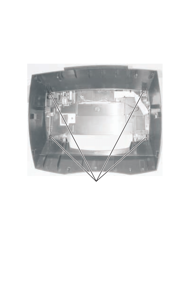
Print engine cover removal
1. Remove scanner lid.
2. Remove scanner assembly.
3. Remove print engine.
4. Remove four screws (A).
A
4-4
Service Manual
4408-XXX
5. Depress six latches (B).
6. Remove print engine cover.
ASF removal
1. Remove scanner lid.
2. Remove scanner assembly.
3. Remove print engine.
B
Repair information
4-5
4408-XXX
4. Disconnect media sensor (A).
5. Remove four screws (B) from ASF.
6. Remove ASF.
Base assembly removal
1. Remove scanner lid.
2. Remove scanner assembly.
3. Remove print engine.
4. Remove print engine cover from base assembly.
A
B
4-6
Service Manual
4408-XXX
Carrier removal
1. Remove scanner lid.
2. Remove scanner assembly.
3. Remove midframe.
4. Remove print engine.
5. Disconnect carrier cables from system board.
6. Loosen carrier belt tensioner screw (A).
A
Repair information
4-7
4408-XXX
7. Depress carrier belt tensioner (B).
8. Remove carrier belt from motor pulley (C).
9. Remove two retainer clips (D) from the carrier shaft.
10. Remove shaft.
11. Lift and remove carrier.
Note:
Position of encoder strip.
Fax card removal
1. Remove scanner lid.
2. Remove scanner assembly.
3. Remove print engine.
4. Remove exit tray.
B
D
D
C
4-8
Service Manual
4408-XXX
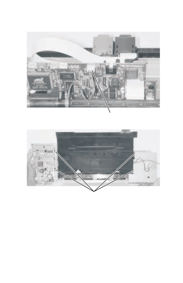
5. Remove fax card cover (A).
6. Remove three fax card screws (B).
7. Remove fax card.
Note:
Routing of all cables.
A
B
Repair information
4-9
4408-XXX
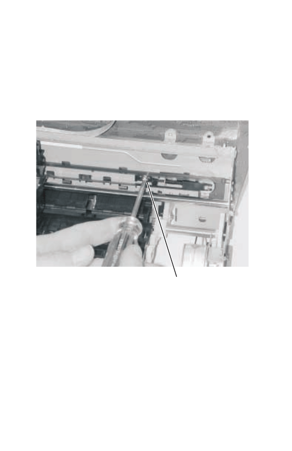
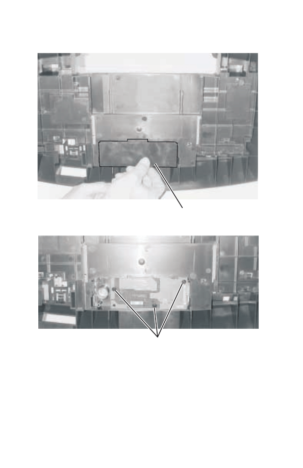
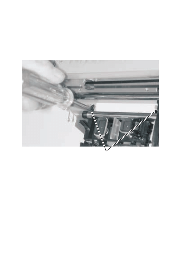
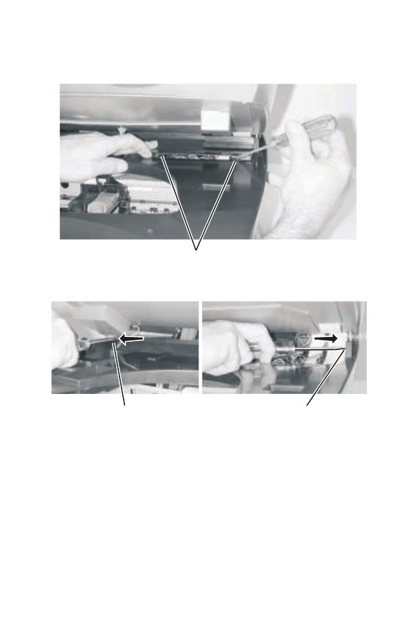
Maintenance station removal
1. Remove scanner lid.
2. Remove scanner assembly.
3. Remove print engine.
4. Use a screwdriver to unlatch maintenance station (A).
A
4-10
Service Manual
4408-XXX
5. Slide maintenance station forward and remove.

Repair information
4-11
4408-XXX
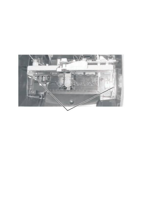
Midframe removal
1. Remove scanner lid.
2. Remove scanner assembly.
3. Remove six screws (A) from midframe.
4. Use screwdriver to unlatch midframe.
5. Remove midframe.
A
Tabs
4-12
Service Manual
4408-XXX
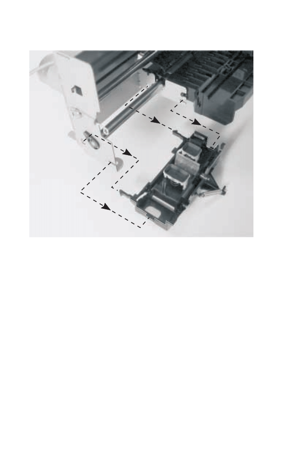
Print engine removal
1. Remove scanner lid.
2. Remove scanner assembly.
3. Remove midframe.
4. Move the carrier to the center of the printer.
5. Remove two screws (A) from print engine.
6. Disconnect cables from system board.
7. LIft and remove print engine.
Scanner lid assembly removal
1. Open the lid.
2. Lift and remove.
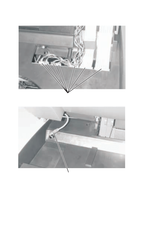
Scanner and ADF assembly removal
1. Remove scanner lid.
2. Lift scanner assembly.
A
Repair information
4-13
4408-XXX
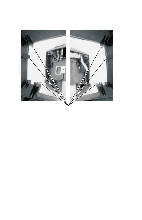
3. With screwdriver depress two clips (A) on cable cover and
remove.
4. Depress clip (B) on left side of scanner assembly.
5. Depress clip (C) on right side of scanner assembly.
A
C
B
4-14
Service Manual
4408-XXX
6. Disconnect all cables (D) from system board.
7. Disconnect ground cable (E).
8. Lift and remove scanner and ADF assembly.
Note:
Routing of all cables.
Note:
Do not lubricate scanner rod or bearing after replacing.
D
E
Repair information
4-15
4408-XXX
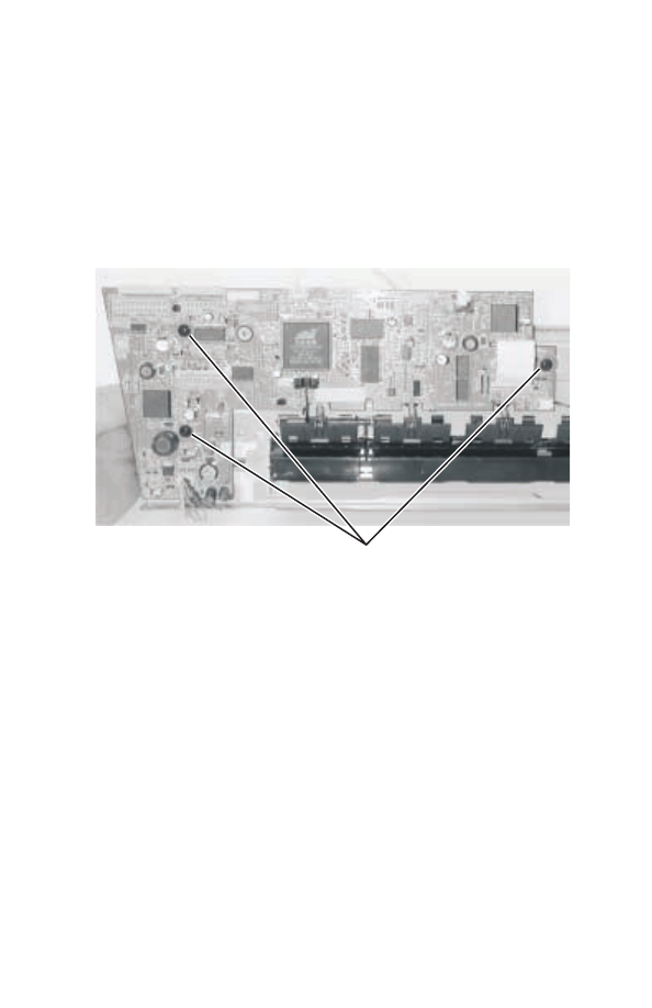
System board removal
1. Remove scanner lid.
2. Remove scanner assembly.
3. Remove print engine.
4. Remove ASF.
5. Disconnect all cables from system board.
6. Remove three screws (A) from system board.
7. Remove system board.
A

4-16
Service Manual
4408-XXX
Connector locations
5-1
4408-XXX
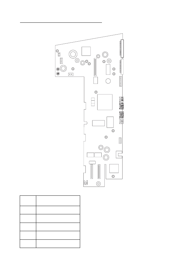
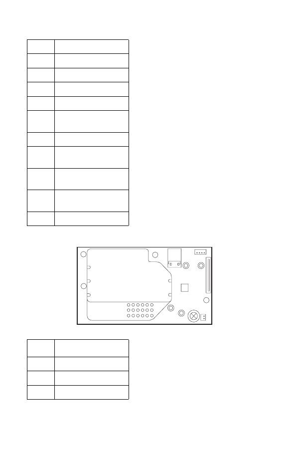
5. Connector locations
Units
Description
J1
ADF Entry Sensor
J2
ADF Exit Sensor
J3
USB and Phone Jacks
J4
Control Panel
JP1
Carrier
JP6
JP16
JP15
J1
J2
J6
PS2
PS1
JP7
JP1
JP2
J3
JP4
JP5
JP9
J4
1
1
1
JP3
1
1
1
1
1
1
1
1
5-2
Service Manual
4408-XXX
JP2
Carrier
JP3
Jumper
JP4
Power Supply Terminal
JP5
Paper Feed Motor
JP6
Media Sensor
JP7
Transport Carrier
Motor
JP9
CCD Module
JP15
ADF Paper Feed
Motor
JP16
CCD Module Scanner
Motor
PS2
Scanner Housing
Sensor
S1
EOF
Units
Description
J1
USB and Phone Jacks
J4
Fax Speaker
JP2
USB
J1
1
J5
J4
JP2
1
J3

Preventive maintenance
6-1
4408-XXX
6. Preventive maintenance
This chapter contains the lubrication specifications. Follow these
recommendations to prevent problems and maintain optimum
performance.
Lubrication specifications
Lubricate only when parts are replaced or as needed, not on a
scheduled basis. Use grease P/N 99A0394 to lubricate the following:
•
All gear mounting studs.
•
The left and right ends of the large feed roller at the side frames.
•
The carrier to carrier frame engagement.
•
The carrier guide rod, and carrier guide rod bearings.
Warning:
Keep grease from coming into contact with any electrical
components, may cause printer damage or failure. Do not lubricate
the scanner rod or bearing after replacing.

6-2
Service Manual
4408-XXX

Parts catalog
7-1
4408-XXX
7. Parts catalog
How to use this parts catalog
•
SIMILAR ASSEMBLIES: If two assemblies contain a majority of
identical parts, they are shown on the same list. Common parts
are shown by one index number. Parts peculiar to one or the
other of the assemblies are listed separately and identified by
description.
•
NS: (Not Shown) in the Asm-Index column indicates that the
part is procurable but is not pictured in the illustration.
•
PP: in the parts description column indicates the part is
available in the listed parts packet.
•
NA: Not available as a FRU.
7-2
Service Manual
4408-XXX
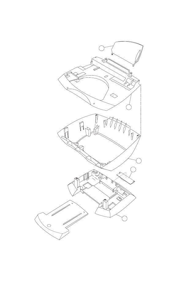
Assembly 1: Covers
3
5
2
4
1

Parts catalog
7-3
4408-XXX
Assembly 1: Covers
Asm-
Index
Part
Number
Units
Description
1-1
56P1778
1
Paper support
2
56P1784
1
Midframe cover
3
56P1783
1
Engine cover
4
56P1786
1
Fax cover
5
56P1781
1
Base assembly
NS
7371533
1
Plain package B/M includes: carton, cushion
set, and sealing tape (001)
NS
7371538
1
Plain package B/M includes: carton, cushion
set, and sealing tape (002)
7-4
Service Manual
4408-XXX
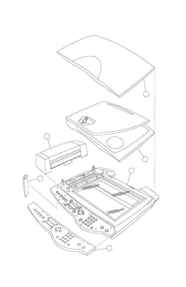
Assembly 1 (cont.): Covers
2
3
4
5
6
1

Parts catalog
7-5
4408-XXX
Assembly 1: (cont.) Covers
Asm-
Index
Part
Number
Units
Description
1-1
56P1780
1
Scanner lid assembly (002)
2
56P1779
1
Scanner lid assembly (001)
3
56P1776
1
Control panel scanner assembly (001)
4
15K0153
1
Cover, control panel, English
5
56P1785
1
Scanner support
6
56P1775
1
ADF Module
NS
56P1777
1
Control panel scanner assembly (002)
NS
56P1789
1
Control panel scanner assebmly (AK1)
NS
56P1790
1
Control panel scanner assembly (AK2)
NS
15K0154
1
Cover, control panel, French
NS
15K0155
1
Cover, control panel, Germany
NS
15K0156
1
Cover, control panel, Spain
NS
15K0157
1
Cover, control panel, Italy
NS
15K0158
1
Cover, control panel, Dutch
NS
15K0159
1
Cover, control panel, Portuguese (Brazil)
NS
15K0160
1
Cover, control panel, Polish
NS
15K0161
1
Cover, control panel, Japanese
NS
15K0162
1
Cover, control panel, Simple Chinese
NS
15K0163
1
Cover, control panel, Traditional Chinese
NS
15K0164
1
Cover, control panel, Russian
NS
15K0167
1
Cover, control panel, Greek
7-6
Service Manual
4408-XXX
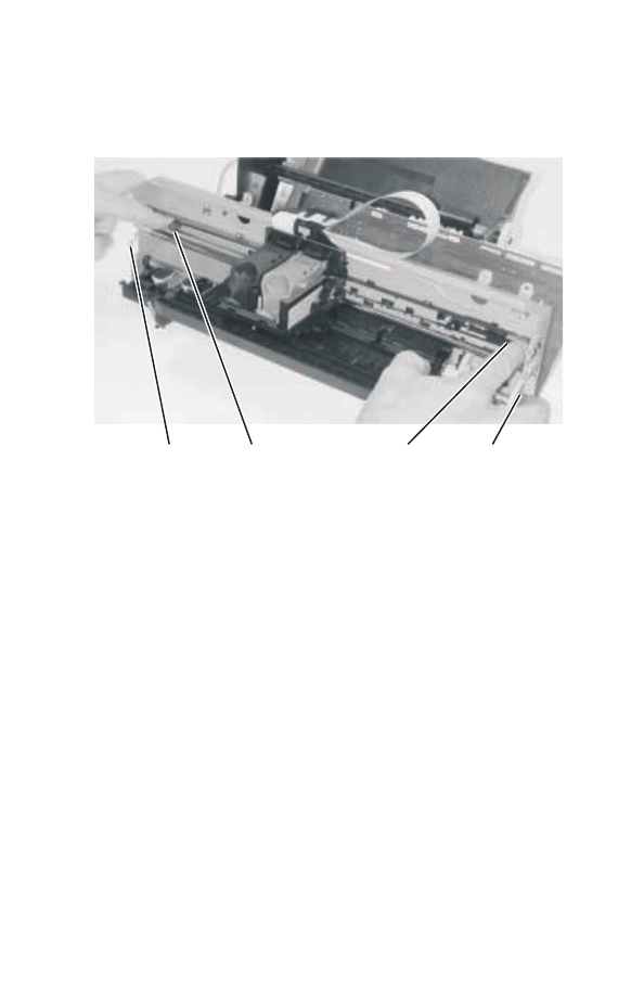
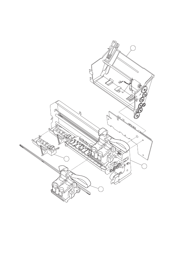
Assembly 2: Paper feed, frame, and carrier
transport
3
2
4
1

Parts catalog
7-7
4408-XXX
Assembly 2: Paper feed, frame, and carrier transport
Asm-
Index
Part
Number
Units
Description
2-1
56P1774
1
ASF module
2
56P1770
1
Printing engine
3
56P1773
1
Carrier w/cable assembly
4
56P1788
1
Maintenance station assembly
7-8
Service Manual
4408-XXX
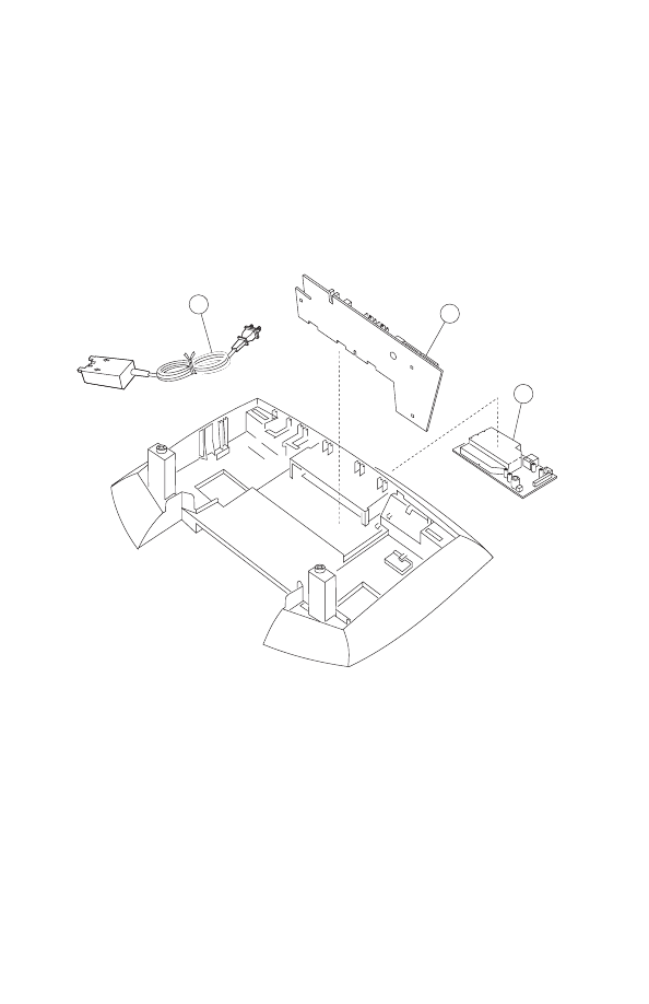
Assembly 3: Electronics
1
2
3

Parts catalog
7-9
4408-XXX
Assembly 3: Electronics
Asm-
Index
Part
Number
Units
Description
3-1
13D0400
1
Power supply (LV) 120 V
2
56P1771
1
Board, system (001)
3
56P1787
1
Fax card
NS
56P1772
1
Board, system (002)
NS
13D0401
1
Power supply (HV) 220 V
NS
13D0402
1
Power supply — Japan 100 V

7-10
Service Manual
4408-XXX

Index
X-1
4408-XXX
Index
A
abbreviations
adjustments
B
button
black copy
color copy
lighter/darker
number of copies
power
quality
reduce/enlarge
scan
select
C
carrier
carrier transport
carrier transport motor cable
cartridge
CCD module assembly
connector locations
control panel
E
ESD-sensitive parts
G
general information
L
LCD
,
lubrication specifications
M
machine types
maintenance approach
P
paper feed motor
paper jam
parts catalog
carrier transport
covers
electronics
frame
paper feed
plastic latches
POST sequence
POST symptom tables
power consumption
preventive maintenance
print quality
printer communication table
problems
carrier transport
control panel
maintenance station
paper feed
power
print quality
scanner
R
removals
ASF
base assembly
carrier
fax card
maintenance station
midframe
print engine
print engine cover
scanner and ADF assembly
scanner lid assembly
system board
S
safety information
scanner assembly
scanner specifications
service checks
carrier transport

X-2
Service Manual
4408-00X
CCD module assembly
maintenance station
paper feed
paper path
power
print quality
scan/copy quality
system board
start
symptom tables
T
table of contents
test page
Part Numbers
13D0400
13D0401
13D0402
15K0153
15K0154
15K0155
15K0156
15K0157
15K0158
15K0159
15K0160
15K0161
15K0162
15K0163
15K0164
15K0167
56P1770
56P1771
56P1772
56P1773
56P1774
56P1775
56P1776
56P1777
56P1778
56P1779
56P1780
56P1781
56P1783
56P1784
56P1785
56P1786
56P1787
56P1788
56P1789
56P1790
7371533
7371538
Document Outline
- Table of contents
- Safety information
- Preface
- 1. General information
- 2. Diagnostic information
- 3. Diagnostic aids
- 4. Repair information
- 5. Connector locations
- 6. Preventive maintenance
- 7. Parts catalog
- Index
Wyszukiwarka
Podobne podstrony:
Chirurgia ALL in ONE
Kartridże atramentowe Dell All in one 922
all in one
łożyska sliz kolos, AGH, Semestr V, PKM [Łukasik], chomik all in one
odpady ściagi all in one
HLP (all in one)
all in one
Obliczenia all in one
ALL in ONE
virtuemart 2 all in one installer
Windows Vista PL2 bit All Versions in One
leach ll in one 246
all in 1
All In The Groove (intro) TAB
130709095732 130625 tews 129 eggs in one basket
więcej podobnych podstron