Air-Conditioners
PCA-RP
•
KA
English
Deutsch
Français
Nederlands
Español
Italiano
Português
Dansk
Svenska
INSTALLATION MANUAL
For safe and correct use, read this manual and the outdoor unit installation manual thoroughly before installing
the air-conditioner unit.
INSTALLATIONSHANDBUCH
Aus Sicherheitsgründen und zur richtigen Anwendung vor Installation der Klimaanlage die vorliegende Bedie-
nungsanleitung und das Installationshandbuch gründlich durchlesen.
MANUEL D’INSTALLATION
Avant d’installer le climatiseur, lire attentivement ce manuel, ainsi que le manuel d’installation de l’appareil exté-
rieur pour une utilisation sûre et correct.
INSTALLATIONSMANUAL
Läs bruksanvisningen och utomhusenhetens installationshandbok noga innan luftkonditioneringen installeras så
att den används på ett säkert och korrekt sätt.
INSTALLATIEHANDLEIDING
Lees deze handleiding en de installatiehandleiding van het buitenapparaat zorgvuldig door voordat u met het
installeren van de airconditioner begint.
MANUALE DI INSTALLAZIONE
Per un uso sicuro e corretto, prima di installare il condizionatore d’aria leggere attentamente il presente manuale
ed il manuale d’installazione dell’unità esterna.
MANUAL DE INSTALACIÓN
Para un uso seguro y correcto, lea detalladamente este manual de instalación antes de montar la unidad de
aire acondicionado.
MANUAL DE INSTALAÇÃO
Para uma utilização segura e correcta, leia atentamente este manual e o manual de instalação da unidade exte-
rior antes de instalar o aparelho de ar condicionado.
INSTALLATIONSMANUAL
Læs af sikkerhedshensyn denne manual samt manualen til installation af udendørsenheden grundigt, før du
installerer klimaanlægget.
FOR INSTALLER
FÜR INSTALLATEURE
TIL INSTALLATØREN
PARA O INSTALADOR
PARA EL INSTALADOR
PER L’INSTALLATORE
VOOR DE INSTALLATEUR
FÖR INSTALLATÖREN
POUR L’INSTALLATEUR
!""#$%&'
!()!*+*,*- -,.(*/0 !(12324324.4
!"# $%$&' (#" #$)#*' +,'$-, ."#/0$&1 2,3$1(&"(0 #4&5 &3 16+1",7."3, (#89: (#" &3 16+1",7."3 16(#&0$&#$-:
&-: 1;%&1,"(': <3=0.#:, 2,"= #25 &-= 16(#&0$&#$- &-: <3=0.#: (*"<#&"$&"(3>.
(*2 253-0 6-5 120!* 3.0 !(12324324.
Türkçe
MONTAJ ELK7TABI
Emniyetli ve do?ru kullanım için, klima cihazını monte etmeden önce bu kılavuzu ve dı@ ünite montaj kılavuzunu
tamamıyla okuyun.
MONTÖR 7Ç7N
89::;<=
8>?@A@BCDA@ E@ >CDFG@A?H
ABC DEFGHFIFJKC EFLDHMGJDN K JMOBFPMQFN RSGHBTMUMVKK WJKXMUFBYJD HZDIUKUF OMJJDF ZTSDWDOGUWD K
ZTSDWDOGUWD HD TGUMJDWSF JMZTPJD[D HZKEDZM HFZFO TGUMJDWSDN SDJOKVKDJFZM.
BIJ >CDFG@AKDHIJ
01̲RG79D451H01̲EN.indd 1
2008/12/17 13:09:34
2
Contents
1. Safety precautions ..................................................................................... 2
2. Installation location .................................................................................... 3
3. Installing the indoor unit ............................................................................ 3
4. Installing the refrigerant piping .................................................................. 5
5. Drainage piping work ................................................................................. 6
6. Electrical work ........................................................................................... 6
7. Test run .................................................................................................... 11
8. Easy maintenance function ..................................................................... 14
1. Safety precautions
L
Before installing the unit, make sure you read all the “Safety precau-
tions”.
L
Please report to your supply authority or obtain their consent before
connecting this equipment to the power supply system.
Warning:
Describes precautions that must be observed to prevent danger of injury or
death to the user.
Caution:
Describes precautions that must be observed to prevent damage to the unit.
After installation work has been completed, explain the “Safety Precautions,” use,
and maintenance of the unit to the customer according to the information in the
Operation Manual and perform the test run to ensure normal operation. Both the
Installation Manual and Operation Manual must be given to the user for keeping.
These manuals must be passed on to subsequent users.
: Indicates a part which must be grounded.
Warning:
Carefully read the labels affi xed to the main unit.
Warning:
• Ask a dealer or an authorized technician to install the unit.
• For installation work, follow the instructions in the Installation Manual and
use tools and pipe components specifi cally made for use with refrigerant
specifi ed in the outdoor unit installation manual.
• The unit must be installed according to the instructions in order to mini-
mize the risk of damage from earthquakes, typhoons, or strong winds. An
incorrectly installed unit may fall down and cause damage or injuries.
• The unit must be securely installed on a structure that can sustain its weight.
• If the air conditioner is installed in a small room, measures must be taken
to prevent the refrigerant concentration in the room from exceeding the
safety limit in the event of refrigerant leakage. Should the refrigerant leak
and cause the concentration limit to be exceeded, hazards due to lack of
oxygen in the room may result.
• Ventilate the room if refrigerant leaks during operation. If refrigerant comes
into contact with a fl ame, poisonous gases will be released.
• All electric work must be performed by a qualifi ed technician according to
local regulations and the instructions given in this manual.
• Use only specifi ed cables for wiring.
• The terminal block cover panel of the unit must be fi rmly attached.
• Use only accessories authorized by Mitsubishi Electric and ask a dealer or
an authorized technician to install them.
• The user should never attempt to repair the unit or transfer it to another
location.
• After installation has been completed, check for refrigerant leaks. If refrig-
erant leaks into the room and comes into contact with the fl ame of a heater
or portable cooking range, poisonous gases will be released.
1.1. Before installation (Environment)
Caution:
• Do not use the unit in an unusual environment. If the air conditioner is in-
stalled in areas exposed to steam, volatile oil (including machine oil), or sulfu-
ric gas, areas exposed to high salt content such as the seaside, the perform-
ance can be signifi cantly reduced and the internal parts can be damaged.
• Do not install the unit where combustible gases may leak, be produced,
fl ow, or accumulate. If combustible gas accumulates around the unit, fi re or
explosion may result.
• Do not keep food, plants, caged pets, artwork, or precision instruments in
the direct airfl ow of the indoor unit or too close to the unit, as these items
can be damaged by temperature changes or dripping water.
• When the room humidity exceeds 80% or when the drainpipe is clogged,
water may drip from the indoor unit. Do not install the indoor unit where
such dripping can cause damage.
• When installing the unit in a hospital or communications office, be pre-
pared for noise and electronic interference. Inverters, home appliances,
high-frequency medical equipment, and radio communications equipment
can cause the air conditioner to malfunction or breakdown. The air con-
ditioner may also affect medical equipment, disturbing medical care, and
communications equipment, harming the screen display quality.
1.2. Before installation or relocation
Caution:
• Be extremely careful when transporting the units. Two or more persons
are needed to handle the unit, as it weighs 20 kg or more. Do not grasp the
packaging bands. Wear protective gloves as you can injure your hands on
the fi ns or other parts.
• Be sure to safely dispose of the packaging materials. Packaging materials,
such as nails and other metal or wooden parts may cause stabs or other
injuries.
• Thermal insulation of the refrigerant pipe is necessary to prevent condensa-
tion. If the refrigerant pipe is not properly insulated, condensation will be
formed.
• Place thermal insulation on the pipes to prevent condensation. If the drain-
pipe is installed incorrectly, water leakage and damage to the ceiling, fl oor,
furniture, or other possessions may result.
• Do not clean the air conditioner unit with water. Electric shock may result.
• Tighten all fl are nuts to specifi cation using a torque wrench. If tightened
too much, the fl are nut can break after an extended period.
1.3. Before electric work
Caution:
• Be sure to install circuit breakers. If not installed, electric shock may result.
• For the power lines, use standard cables of suffi cient capacity. Otherwise,
a short circuit, overheating, or fi re may result.
• When installing the power lines, do not apply tension to the cables.
• Be sure to ground the unit. If the unit is not properly grounded, electric
shock may result.
• Use circuit breakers (ground fault interrupter, isolating switch (+B fuse),
and molded case circuit breaker) with the specifi ed capacity. If the circuit
breaker capacity is larger than the specifi ed capacity, breakdown or fi re
may result.
1.4. Before starting the test run
Caution:
• Turn on the main power switch more than 12 hours before starting opera-
tion. Starting operation just after turning on the power switch can severely
damage the internal parts.
• Before starting operation, check that all panels, guards and other protec-
tive parts are correctly installed. Rotating, hot, or high voltage parts can
cause injuries.
• Do not operate the air conditioner without the air fi lter set in place. If the air
fi lter is not installed, dust may accumulate and breakdown may result.
• Do not touch any switch with wet hands. Electric shock may result.
• Do not touch the refrigerant pipes with bare hands during operation.
• After stopping operation, be sure to wait at least fi ve minutes before turn-
ing off the main power switch. Otherwise, water leakage or breakdown may
result.
01̲RG79D451H01̲EN.indd 2
2008/12/17 13:09:49
3
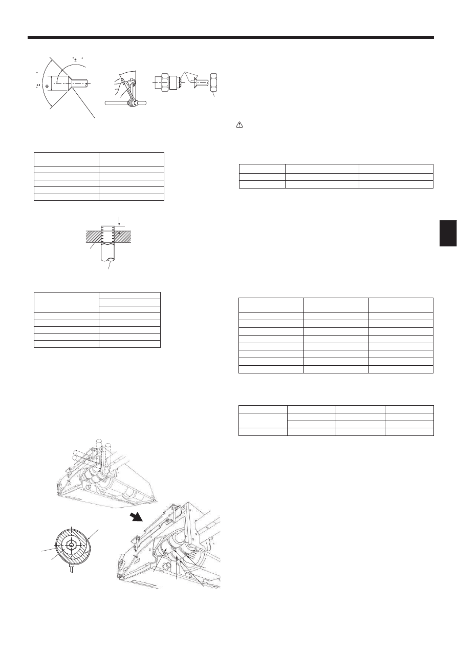
3. Installing the indoor unit
2. Installation location
(mm)
3.1. Check the indoor unit accessories (Fig. 3-1)
The indoor unit should be supplied with the following accessories
(contained in the inside of the intake grille).
Accessory name
Q’ty
1
Washer
4 pcs
2
Pipe cover
1 pc Large size (For gas tubing)
3
Pipe cover
1 pc Small size (For liquid tubing)
4
Band
4 pcs
5
Joint socket
1 pc Marked with “UNIT”
6
Socket cover
1 pc
7
Drain tubing cover
1 pc
8
Wired remote controller
1 pc
9
Flare nut
1 pc ø6.35 (RP60 only)
3.2. Preparation for installation (Fig. 3-2)
3.2.1. Suspension bolt installing spacing
(mm)
Models
A
B
RP50
917
960
RP60,71
1237
1280
RP100,125 ,140
1557
1600
3.2.2. Refrigerant and drain tubing location
(mm)
Models
C
D
RP50
184
203
RP60
179
203
RP71-140
180
200
A
Front side outlet
F
Left drain tubing
B
Left side outlet
G
Gas tubing
C
Right side outlet
H
Liquid tubing
D
Independent piece (Removable)
I
Rubber plug
E
Right drain tubing
J
with Joint socket 5
In case of the rear pipe arrangement, make sure to remove the shaded portions
from the D independent piece. Then put the D independent piece back in initial
position.
(The heat exchanger might be clogged because of dust)
23
6
Mi
n.500
680
Max.250
W
Min.270
Min.300
1
2
3
4
5
6
7
8
9
A
236
B
2
75
80
32
0
68
0
2
19
0
46
6
233
246
C
D
233
246
86 2
85
138
12
6
19
0
46
Fig. 2-1
2.1. Outline dimensions (Indoor unit) (Fig. 2-1)
Select a proper position allowing the following clearances for installation and main-
tenance.
Models
W
RP50
960
RP60,71
1280
RP100 ,125,140
1600
Warning:
Mount the indoor unit on a ceiling strong enough to withstand the weight of
the unit.
2.2. Outline dimensions (Outdoor unit)
Refer to the outdoor unit installation manual.
Fig. 3-1
!"#$
Fig. 3-2
(mm)
01̲RG79D451H01̲EN.indd 3
2008/12/17 13:09:50
4
3. Installing the indoor unit
3.3. Installing the indoor unit (Fig. 3-5)
Use a proper suspending method depending on the presence or absence of ceiling
materials as follows.
A
In the presence of ceiling materials
c
Ceiling
B
In the absence of ceiling materials
d
Suspending bolt
a
Suspending bracket
e
Washer 1
b
Unit
f
Washer (Local procurement)
g
Double nuts
1) Directly suspending the unit
Installing procedures
1. Install the washer 1 (supplied with the unit) and the nuts (to be locally procured).
2. Set (hook) the unit through the suspending bolts.
3. Tighten the nuts.
Check the unit installing condition.
• Check that the unit is horizontal between the right and left sides.
• Check that the front and the rear of suspending brackets are horizontal.
(To keep drainage,the unit is inclined to the suspending brackets. The unit slopes
continuously downward from the front to the rear is the right installation position.)
2) Installing the suspending bracket fi rst onto the ceiling (Fig. 3-6)
Installing procedures
1. Remove the suspending brackets and U-shaped washers from the unit.
2. Adjust the suspending bracket holding bolts on the unit.
3. Attach the suspending brackets to the suspending bolts.
4. Check that the suspending brackets are horizontal (front and rear / right and left).
5. Set (hook) the unit to the suspending brackets.
6. Tighten fi xed bolts of the suspending brackets.
w
Be sure to install the U-shaped washers.
A
Suspending bracket holding bolt
B
Unit
C
U-shaped washer
D
Suspending bolt
E
Washer 1
F
Double nuts
(mm)
10
–2
0
125
175
190
70
80 ø65
ø100
7~12
3.2.3. Selection of suspension bolts and tubing positions (Fig. 3-3)
Using the pattern paper provided for installation, select proper positions for suspen-
sion bolts and tubing and prepare relative holes.
A
Pattern paper
B
Suspension bolt hole
C
Indoor unit width
Secure the suspension bolts or use angle stock braces or square timbers for bolt
installation.
D
Use inserts of 100 kg to 150 kg each.
E
Use suspension bolts of W3/8 or M10 in size.
3.2.4. Indoor unit preparation (Fig. 3-4)
1. Install the suspending bolts. (Procure the W3/8 or M10 bolts locally.)
Predetermine the length from the ceiling (1 within 100 mm).
A
Ceiling surface B Suspending bolt C Suspending bracket
2. Remove the intake grille.
Slide the intake grille holding knobs (at 2 or 3 locations) backward to open the
intake grille.
3. Remove the side panel.
Remove the side panel holding screws (one in each side, right and left) then slide
the side panel forward for removal.
D
Intake grille
J
Slide the side panel forward.
E
Intake grille holding knob
K
Side panel
F
Slide
L
Remove the side panel holding screws.
G
Hinge
M
Remove the protective vinyl of vane.
H
Pushing the hinge, pull out the intake grille.
2
Forcing open the intake grille or opening it to an angle of more than 120° may
damage the hinges.
Fig. 3-4
Fig. 3-5
Fig. 3-3
Fig. 3-6
(mm)
G
RP50
882-887
RP60,71
1202-1207
RP100 -140
1522-1527
01̲RG79D451H01̲EN.indd 4
2008/12/17 13:09:53
5
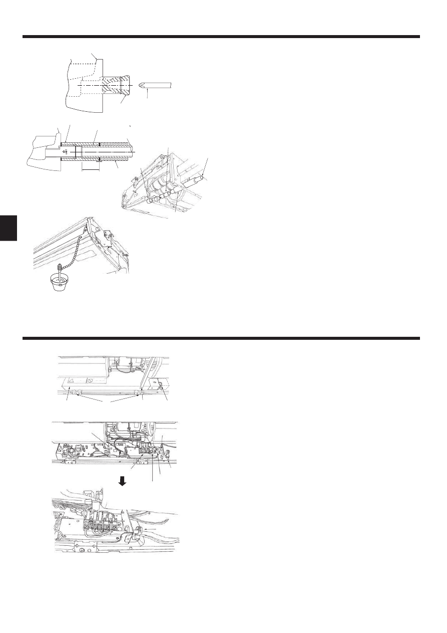
4. Installing the refrigerant piping
4.3. Indoor unit (Fig. 4-3)
Installing procedures
1. Slide the supplied pipe cover 2 over the gas tubing until it is pressed against the
sheet metal inside the unit.
2. Slide the provided pipe cover 3 over the liquid tubing until it is pressed against
the sheet metal inside the unit.
3. Tighten the pipe covers 2 and 3 at the both ends (20 mm) with the supplied
bands 4.
A
Gas tubing
E
Pipe cover 3
B
Liquid tubing
F
Press the pipe cover against the sheet metal.
C
Band 4
G
Refrigerant tubing heat insulating material
D
Pipe cover 2
4.4. For twin/triple combination
Refer to the outdoor unit installation manual.
4.1. Precautions
For devices that use R410A refrigerant
• Use ester oil, ether oil or alkylbenzene oil (small amount) as the refrigera-
tion oil applied to the fl ared sections.
• Use C1220 copper phosphorus for copper and copper alloy seamless
pipes, to connect the refrigerant pipes. Use refrigerant pipes with the thick-
nesses specifi ed in the table below. Make sure the insides of the pipes are
clean and do not contain any harmful contaminants such as sulfuric com-
pounds, oxidants, debris, or dust.
Warning:
When installing or moving the air conditioner, use only the specifi ed refriger-
ant (R410A) to charge the refrigerant lines. Do not mix it with any other refrig-
erant and do not allow air to remain in the lines. Air enclosed in the lines can
cause pressure peaks resulting in a rupture and other hazards.
RP35, 50
RP60-140
Liquid pipe
[ 6.35 thickness 0.8 mm
[ 9.52 thickness 0.8 mm
Gas pipe
[ 12.7 thickness 0.8 mm
[ 15.88 thickness 1.0 mm
• Do not use pipes thinner than those specifi ed above.
4.2. Connecting pipes (Fig. 4-1)
• When commercially available copper pipes are used, wrap liquid and gas pipes
with commercially available insulation materials (heat-resistant to 100 °C or
more, thickness of 12 mm or more).
• The indoor parts of the drain pipe should be wrapped with polyethylene foam in-
sulation materials (specifi c gravity of 0.03, thickness of 9 mm or more).
• Apply thin layer of refrigerant oil to pipe and joint seating surface before tighten-
ing fl are nut.
• Use 2 wrenches to tighten piping connections.
• Use refrigerant piping insulation provided to insulate indoor unit connections. In-
sulate carefully.
B
Flare nut tightening torque
Copper pipe O.D.
(mm)
Flare nut O.D.
(mm)
Tightening torque
(N·m)
[6.35
17
14-18
[6.35
22
34-42
[9.52
22
34-42
[12.7
26
49-61
[12.7
29
68-82
[15.88
29
68-82
[15.88
36
100-120
[19.05
36
100-120
C
Apply refrigerating machine oil over the entire fl are seat surface.
D
Use correct fl are nuts meeting the pipe size of the outdoor unit.
Available pipe size
RP35, 50
RP60
RP71-140
Liquid side
[6.35 \
[6.35
—
—
[9.52 \
[9.52 \
Gas side
[12.7 \
[15.88 \
[15.88 \
\ : Factory fl are nut attachment to the heat exchanger.
Flare cutting dimensions
Copper pipe O.D.
Flare dimensions
(mm)
:
A dimensions (mm)
:
6.35
8.7 - 9.1
:
9.52
12.8 - 13.2
:
12.7
16.2 - 16.6
:
15.88
19.3 - 19.7
:
19.05
23.6 - 24.0
90
0.5 A
R0.4
~R0
.8
45 2
Fig. 4-1
Die
Copper pipe
B
Fig. 4-2
Copper pipe O.D.
B (mm)
(mm)
Flare tool for R410A
Clutch type
:
6.35 (1/4")
0 - 0.5
:
9.52 (3/8")
0 - 0.5
:
12.7 (1/2")
0 - 0.5
:
15.88 (5/8")
0 - 0.5
:
19.05 (3/4")
0 - 0.5
Fig. 4-3
01̲RG79D451H01̲EN.indd 5
2008/12/17 13:09:55
6
5. Drainage piping work
6. Electrical work
• For left side tubing, be sure to insert the rubber plug into the right drain port. (Fig.
5-1)
• Use VP-20 (O.D. ø26 (1”) PVC TUBE) for drain piping and provide 1/100 or more
downward slope.
• After completion of work, check that correct drain is available from the outfl ow
port of the drain tubing.
A
Drain pan
B
Plug
C
Insert the driver etc.in the plug deeply.
Installing procedures (Fig. 5-2)
1. Attach the joint socket 5 supplied with the unit to the drain port on the unit with a
vinyl chloride adhesive.
2. Fasten the socket cover 6 supplied with the unit to the joint socket 5.
3. Attach the fi eld drain tubing (VP-20) to the joint socket 5 with a vinyl chloride
adhesive.
4. Wrap the drain tubing cover 7 supplied with the unit. (Seam taping)
A
Drain pan
B
Drain tubing
C
Socket cover 6
D
Joint socket 5
E
Drain tubing cover 7
F
Insertion length 37mm
5. Check for correct drainage. (Fig. 5-3)
* Fill the drain pan with water of about 1 L from the air outlet.
6.1. Electric wiring (Fig. 6-1)
Wiring procedures
1. Remove the tapping screw C then remove the beam.
2. Remove the (2) tapping screws B then remove the electric part cover A.
3. Connect the electric wires securely to the corresponding terminals.
4. Replace the removed parts.
5. Tie the electric wires with the local wiring clamp located in the right side of the
junction box.
A
Cover
H
Grounding cable connector
B
Set screws (2 pcs)
I
Terminal block for Remote controller
C
Set screws (Beam)
i
Secure with the wiring clamp.
D
Wiring clamp
E
Control board
F
Wire service entrance
G
Terminal block for indoor and outdoor units connection
Fig. 5-1
Fig. 5-2
Fig. 5-3
Fig. 6-1
01̲RG79D451H01̲EN.indd 6
2008/12/17 13:09:56
7
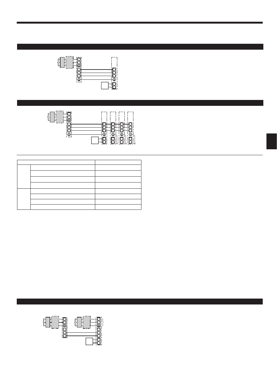
6.1.1. Indoor unit power supplied from outdoor unit
The following connection patterns are available.
The outdoor unit power supply patterns vary on models.
1 System
S1
S2
L
N
1
2
S1
S2
S3
S3
A B
C
D
E
F
G
S1
S2
L
N
1
2
S1
S2
S3
1
2
S1
S2
S3
S3
1
2
S1
S2
S3
1
2
S1
S2
S3
A B C
D
E
F
G
G
G
G
H
H
H
* Affi x label A that is included with the manuals near each wiring diagram for the indoor and outdoor units.
A Outdoor unit power supply
B Earth leakage breaker
C Wiring circuit breaker or isolating switch
D Outdoor unit
E Indoor unit/outdoor unit connecting cables
F Remote controller
G Indoor unit
* Affi x label A that is included with the manuals near each wiring diagram for the indoor and outdoor units.
Indoor unit model
PCA
Wiring
Wire No. × size
(mm²)
Indoor unit-Outdoor unit
*1
3× 1.5 (polar)
Indoor unit-Outdoor unit earth
*1
1 × Min.1.5
Indoor unit earth
1 × Min.1.5
Remote controller-Indoor unit
*2
2 × 0.3 (Non-polar)
Circuit rating
Indoor unit (Heater) L-N
*3
-
Indoor unit-Outdoor unit S1-S2
*3
AC 230 V
Indoor unit-Outdoor unit S2-S3
*3
DC24 V
Remote controller-Indoor unit
*3
DC12 V
*1. <For 50-140 outdoor unit application>
Max. 45 m
If 2.5 mm
2
used, Max. 50 m
If 2.5 mm
2
used and S3 separated, Max. 80 m
<For 200/250 outdoor unit application>
Max. 18 m
If 2.5 mm
2
used, Max. 30 m
If 4 mm
2
used and S3 separated, Max. 50 m
If 6 mm
2
used and S3 separated, Max. 80 m
*2. The 10 m wire is attached in the remote controller accessory. Max. 500 m
*3. The fi gures are NOT always against the ground.
S3 terminal has DC 24 V against S2 terminal. However between S3 and S1, these terminals are not electrically insulated by the transformer or other device.
Notes: 1. Wiring size must comply with the applicable local and national code.
2. Power supply cords and indoor unit/outdoor unit connecting cords shall not be lighter than polychloroprene sheathed fl exible cord.
(Design 60245 IEC 57)
3. Install an earth longer than other cables.
Simultaneous twin/triple/quadruple system
1:1 System
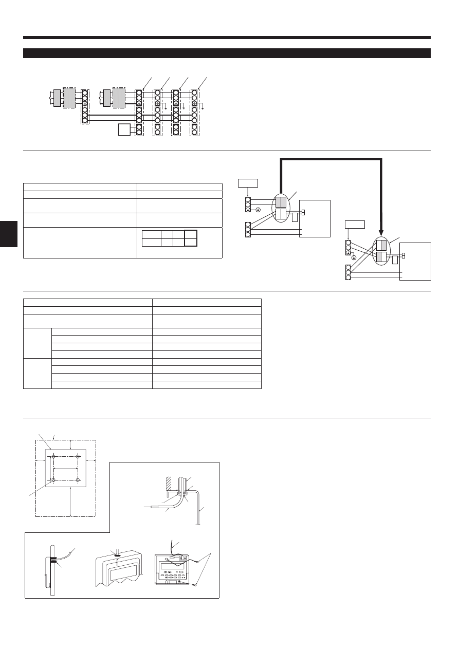
6.1.2. Separate indoor unit/outdoor unit power supplies (For PUHZ application only)
The following connection patterns are available.
The outdoor unit power supply patterns vary on models.
1:1 System
6. Electrical work
A Outdoor unit power supply
B Earth leakage breaker
C Wiring circuit breaker or isolating switch
D Outdoor unit
E Indoor unit/outdoor unit connecting cables
F Remote controller
G Indoor unit
H Indoor unit earth
* The indoor power supply terminal kit is required.
A Outdoor unit power supply
B Earth leakage breaker
C Wiring circuit breaker or isolating switch
D Outdoor unit
E Indoor unit/outdoor unit connecting cables
F Remote controller
G Indoor unit
H Option
J Indoor unit power supply
* Affi x label B that is included with the manuals near each wiring diagram for the indoor and outdoor units.
S1
S2
L
N
1
2
L
N
S1
S2
S3
S3
A
C
B
D
J
E
B C
F
G
H
01̲RG79D451H01̲EN.indd 7
2008/12/17 13:09:59
8
6. Electrical work
Simultaneous twin/triple/quadruple system
6.2. Remote controller
6.2.1. For wired remote controller
1) Installing procedures
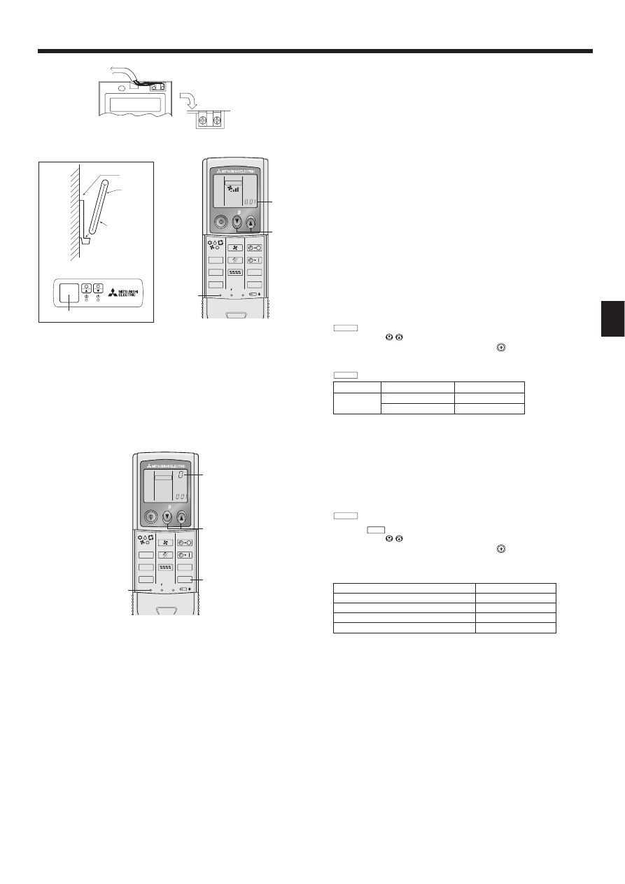
(1) Select an installing position for the remote controller. (Fig. 6-2)
The temperature sensors are located on both remote controller and indoor unit.
L Procure the following parts locally:
2 piece switch box
Thin copper conduit tube
Lock nuts and bushings
[Fig.6-2]
A
Remote controller profi le
B
Required clearances surrounding the remote controller
C
Installation pitch
(2) Seal the service entrance for the remote controller cord with putty to prevent
possible invasion of dew drops, water, cockroaches or worms. (Fig. 6-3)
A
For installation in the switch box
B
For direct installation on the wall, select one of the following:
• Prepare a hole through the wall to pass the remote controller cord (in order to run
the remote controller cord from the back), then seal the hole with putty.
• Run the remote controller cord through the cut-out upper case, then seal the cut-
out notch with putty.
B-1. To lead the remote controller cord from the back of the controller
B-2. To run the remote controller cord through the upper portion
[Fig.6-3]
C
Wall
E
Lock nut
G
Switch box
I
Seal with putty
D
Conduit
F
Bushing
H
Remote controller cord
J
Wood screw
* Affi x label B that is included with the manuals near each wiring diagram for the indoor and outdoor units.
If the indoor and outdoor units have separate power supplies, refer to the table
below. If the indoor power supply terminal kit is used, change the indoor unit elec-
trical box wiring refering to the fi gure in the right and the DIP switch settings of the
outdoor unit control board.
Indoor unit specifi cations
Indoor power supply terminal kit (option)
Required
Indoor unit electrical box connector connec-
tion change
Required
Label affixed near each wiring diagram for
the indoor and outdoor units
Required
Outdoor unit DIP switch settings (when us-
ing separate indoor unit/outdoor unit power
supplies only)
* There are 3 types of labels (labels A, B and C). Affi x the appropriate labels to the
units according to the wiring method.
Indoor unit model
PCA
*1. A breaker with at least 3.0 mm contact separation in each pole shall be pro-
vided. Use earth leakage breaker (NV).
The breaker shall be provided to ensure disconnection of all active phase
conductors of the supply.
*2. Max. 120 m
*3. The 10 m wire is attached in the remote controller accessory. Max. 500 m
*4. The fi gures are NOT always against the ground.
Indoor unit power supply
~/N (single), 50 Hz, 230 V
Indoor unit input capacity
Main switch (Breaker)
*1
16 A
Wiring
Wire No. ×
size (mm²)
Indoor unit power supply & earth
3 × Min. 1.5
Indoor unit-Outdoor unit
*2
2 × Min. 0.3
Indoor unit-Outdoor unit earth
–
Remote controller-Indoor unit
*3
2 × 0.3 (Non-polar)
Circuit
rating
Indoor unit L-N
*4
AC 230 V
Indoor unit-Outdoor unit S1-S2
*4
–
Indoor unit-Outdoor unit S2-S3
*4
DC24 V
Remote controller-Indoor unit
*4
DC12 V
Notes: 1. Wiring size must comply with the applicable local and national code.
2. Power supply cords and indoor unit/outdoor unit connecting cords shall not be lighter than polychloroprene sheathed fl exible cord. (Design 60245 IEC 57)
3. Install an earth longer than other cables.
A Outdoor unit power supply
B Earth leakage breaker
C Wiring circuit breaker or isolating switch
D Outdoor unit
E Indoor unit/outdoor unit connecting cables
F Remote controller
G Indoor unit
H Option
J Indoor unit power supply
K Indoor unit earth
30
30
30
120
83.5
B-1.
B-2.
Fig. 6-3
Fig. 6-2
46
S1
S2
L
N
1
2
L
N
S1
S2
S3
1
2
L
N
S1
S2
S3
1
2
L
N
S1
S2
S3
1
2
L
N
S1
S2
S3
S3
A B C
D
E
J
B C
F
H
G
G
G
G
K
K
K
H
H
H
ON
OFF 1 2
(SW8)
3
S1
S2
S3
L
N
BLU
E
BLU
E
YELLOW YELLOW
CN
01
CN01
BLACK
CN01
BLACK
S1
S2
S3
L
N
YELLOW BLUE
BLUE YELLOW
CN
01
* The indoor power supply terminal kits are required.
Set the SW8-3 to ON.
Option
Option
Indoor unit power supplied from outdoor unit
(initial setting)
Separate indoor unit/outdoor unit power supplies
Connectors (connections of initial setting
are for indoor unit power supplied from
outdoor unit)
If the indoor and
outdoor units have
separate power
supplies, change the
connections of the
connectors as shown
in the following
fi gure.
Connectors
Indoor unit
control board
Indoor unit
control board
01̲RG79D451H01̲EN.indd 8
2008/12/17 13:10:03
9
6. Electrical work
2) Connecting procedures (Fig. 6-4)
1
Connect the remote controller cord to the terminal block.
A
To TB5 on the indoor unit
B
TB6 (No polarity)
3) 2 remote controllers setting
If 2 remote controllers are connected, set one to “Main” and the other to “Sub”. For
setting procedures, refer to “Function selection of remote controller” in the opera-
tion manual for the indoor unit.
6.2.2. For wireless remote controller
1) Installation area
• Area in which the remote controller is not exposed to direct sunshine.
• Area in which there is no nearby heating source.
• Area in which the remote controller is not exposed to cold (or hot) winds.
• Area in which the remote controller can be operated easily.
• Area in which the remote controller is beyond the reach of children.
2) Installation method (Fig. 6-5)
1
Attach the remote controller holder to the desired location using 2 tapping screws.
2
Place the lower end of the controller into the holder.
A
Remote controller
B
Wall C Display panel D Receiver
• The signal can travel up to approximately 7 meters (in a straight line) within 45
degrees to both right and left of the center line of the receiver.
3) Setting (Fig. 6-6)
1
Insert batteries.
2
Press the SET button with something sharp at the end.
MODEL SELECT
blinks and Model No. is lighted.
3
Press the temp
buttons to set the Model No.
If you mistook the operation, press the ON/OFF
button and operate again
from procedure 3.
4
Press the SET button with something sharp at the end.
MODEL SELECT
and Model No. are lighted for 3 seconds, then turned off.
Indoor
Outdoor
A
Model No.
PCA
PUH, PUHZ, SUZ
001
PU
033
4)Assigning a remote controller to each unit (Fig. 6-7)
Each unit can be operated only by the assigned remote controller.
Make sure each pair of an indoor unit PC board and a remote controller is assigned
to the same pair No.
5) Wireless remote controller pair number setting operation
1
Press the SET button with something sharp at the end.
Start this operation from the status of remote controller display turned off.
MODEL SELECT
blinks and Model No. is lighted.
2
Press the
min
button twice continuously. Pair No. “0” blinks.
3
Press the temp
buttons to set the pair number you want to set.
If you mistook the operation, press the ON/OFF
button and operate again
from procedure 2.
4
Press the SET button with something sharp at the end.
Set pair number is lighted for 3 seconds then turned off.
A
Pair No. of wireless remote controller
Indoor PC board
0
Initial setting
1
Cut J41
2
Cut J42
3-9
Cut J41, J42
ON/OFF
TEMP
RESET
SET
CLOCK
MODEL SELECT
FAN
VANE
TEST RUN
AUTO STOP
AUTO START
h
min
LOUVER
MODE
CHECK
Fig. 6-6
B
TB
Fig. 6-4
Fig. 6-5
A
6
Fig. 6-7
ON/OFF
TEMP
FAN
VANE
TEST RUN
AUTO STOP
AUTO START
h
min
LOUVER
MODE
CHECK
RESET
SET
CLOCK
MODEL SELECT
01̲RG79D451H01̲EN.indd 9
2008/12/17 13:10:05
10
6.3. Function settings
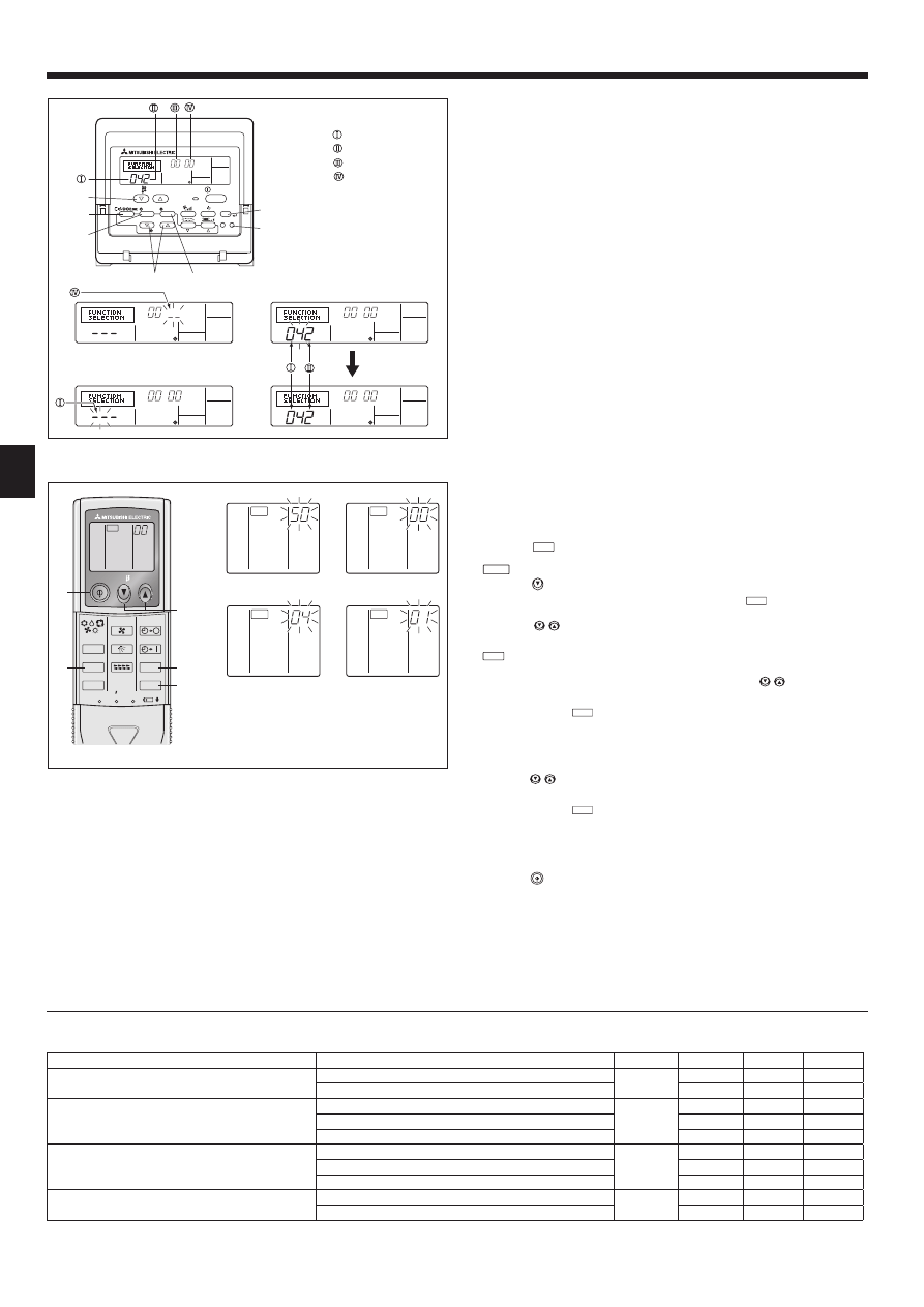
6.3.1. Function setting on the unit (Selecting the unit functions)
1) For wired remote controller (Fig. 6-8)
Changing the power voltage setting
• Be sure to change the power voltage setting depending on the voltage used.
1
Go to the function setting mode.
Switch OFF the remote controller.
Press the FILTER A and TEST RUN B buttons simultaneously and hold
them for at least 2 seconds. FUNCTION will start to blink.
2
Use the C buttons to set the refrigerant address (3) to 00.
3
Press D button and [--] will start to blink in the unit number (4) display.
4
Use the C buttons to set the unit number (4) to 00.
5
Press the MODE button E to designate the refrigerant address/unit number. [--]
will blink in the mode number (1) display momentarily.
6
Press the F buttons to set the mode number (1) to 04.
7
Press the G button and the current set setting number (2) will blink.
Use the F button to switch the setting number in response to the power supply
voltage to be used.
Power supply voltage
240 V
: setting number = 1
220 V, 230 V : setting number = 2
8
Press the MODE button E and mode and the setting number (1) and (2) will
change to being on constantly and the contents of the setting can be confi rmed.
9
Press the FILTER A and TEST RUN B buttons simultaneously for at least 2
seconds. The function selection screen will disappear momentarily and the air
conditioner OFF display will appear.
2) For wireless remote controller (Fig. 6-9)
Changing the power voltage setting
• Be sure to change the power voltage setting depending on the voltage used.
1
Going to the function select mode
Press the
CHECK
button F twice continuously.
(Start this operation from the status of remote controller display turned off.)
CHECK
is lighted and “00” blinks.
Press the
temp button C once to set “50”. Direct the wireless remote control-
ler toward the receiver of the indoor unit and press the
h
button A.
2
Setting the unit number
Press the
temp buttons C and D to set the unit number “00”. Direct the
wireless remote controller toward the receiver of the indoor unit and press the
min
button B.
3
Selecting a mode
Enter 04 to change the power voltage setting using the
temp buttons C
and D. Direct the wireless remote controller toward the receiver of the indoor
unit and press the
h
button A.
Current setting number:
1 = 1 beep (1 second)
2 = 2 beeps (1 second each)
3 = 3 beeps (1 second each)
4
Selecting the setting number
Use the
temp buttons C and D to change the power voltage setting to
01 (240 V). Direct the wireless remote controller toward the sensor of the indoor
unit and press the
h
button A.
5
To select multiple functions continuously
Repeat steps 3 and 4 to change multiple function settings continuously.
6
Complete function selection
Direct the wireless remote controller toward the sensor of the indoor unit and
press the
button E.
Note: Whenever changes are made to the function settings after installation
or maintenance, be sure to record the changes with a mark in the “Setting”
column of the Function table.
6.3.2. Function setting on the remote controller
Refer to the indoor unit operation manual.
6. Electrical work
Function table
Select unit number 00
Mode
Settings
Mode no.
Setting no. Initial setting
setting
Power failure automatic recovery
Not available
01
1
Available
w
2
\
Indoor temperature detecting
Indoor unit operating average
02
1
\
Set by indoor unit’s remote controller
2
Remote controller’s internal sensor
3
LOSSNAY connectivity
Not Supported
03
1
\
Supported (indoor unit is not equipped with outdoor-air intake)
2
Supported (indoor unit is equipped with outdoor-air intake)
3
Power voltage
240 V
04
1
220 V, 230 V
2
\
Fig. 6-8
CHECK
CHECK
ON/OFF
TEMP
FAN
VANE
TEST RUN
AUTO STOP
AUTO START
h
min
LOUVER
MODE
CHECK
RESET
SET
CLOCK
CHECK
Fig. 6-9
CHECK
CHECK
Mode number
Setting number
Refrigerant address
Unit number
PAR-21MAA
ON/OFF
FILTER
CHECK
OPERATION
CLEAR
TEST
TEMP.
MENU
BACK
DAY
MONITOR/SET
CLOCK
ON/OFF
01̲RG79D451H01̲EN.indd 10
2008/12/17 13:10:08
11
6. Electrical work
7. Test run
7.1. Before test run
L After completing installation and the wiring and piping of the indoor and
outdoor units, check for refrigerant leakage, looseness in the power sup-
ply or control wiring, wrong polarity, and no disconnection of one phase
in the supply.
L Use a 500-volt megohmmeter to check that the resistance between the
power supply terminals and ground is at least 1.0 M .
L Do not carry out this test on the control wiring (low voltage circuit) termi-
nals.
Warning:
Do not use the air conditioner if the insulation resistance is less than 1.0 M .
7.2. Test run
The following 3 methods are available.
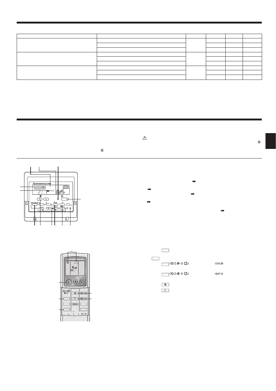
7.2.1. Using wired remote controller (Fig. 7-1)
1
Turn on the power at least 12 hours before the test run.
2
Press the [TEST] button twice.
“TEST RUN” liquid crystal display
3
Press the [Mode selection] button and switch to the cooling (or heating) mode.
Make sure that cold (or warm) wind is blown out.
4
Press the [Fan speed] button.
Make sure that the wind speed is switched.
5
Press the [Air direction button] or [Louver button].
Check operation of the vane or louver.
6
Check operation of the outdoor unit fan.
7
Release test run by pressing the [ON/OFF] button.
Stop
8
Register a telephone number.
The telephone number of the repair shop, sales offi ce, etc., to contact if an error
occurs can be registered in the remote controller. The telephone number will be
displayed when an error occurs. For registration procedures, refer to the opera-
tion manual for the indoor unit.
7.2.2. Using wireless remote controller (Fig. 7-2)
1
Turn on the power to the unit at least 12 hours before the test run.
2
Press the
TEST RUN
button twice continuously.
(Start this operation from the status of remote controller display turned off.)
A
TEST RUN
and current operation mode are displayed.
3
Press the
MODE
button to activate
mode, then check whether
cool air is blown out from the unit.
4
Press the
MODE
button to activate
mode, then check whether
warm air is blown out from the unit.
5
Press the
FAN
button and check whether fan speed changes.
6
Press the
VANE
button and check whether the auto vane operates properly.
7
Press the ON/OFF button to stop the test run.
Note:
• Point the remote controller towards the indoor unit receiver while following
steps
2
to
7
.
• It is not possible to run the TEST RUN in FAN, DRY or AUTO mode.
7.2.3. Using SW4 in outdoor unit
Refer to the outdoor unit installation manual.
ON/OFF
TEMP
FAN
VANE
TEST RUN
AUTO STOP
AUTO START
h
min
LOUVER
MODE
CHECK
RESET
SET
CLOCK
TEST RUN
Fig. 7-2
Fig. 7-1
°C
°C
SIMPLE
PAR-21MAA
ON/OFF
FILTER
CHECK
OPERATION
CLEAR
TEST
TEMP.
MENU
BACK
DAY
MONITOR/SET
CLOCK
ON/OFF
TEST RUN
COOL, HEAT
ON/OFF button
Test run display
Liquid pipe (Indoor unit)
temperature display
ON/OFF lamp
Power display
Error code display
Test run remaining time display
Set temperature button
Mode selection button
Air direction button
TEST button
Fan Speed button
Louver button
Select unit numbers 01 to 03 or all units (AL [wired remote controller]/07 [wireless remote controller])
Mode
Settings
Mode no.
Setting no. Initial setting
setting
Filter sign
100Hr
07
1
2500Hr
2
\
No fi lter sign indicator
3
Fan speed
Silent
08
1
Standard
2
\
High ceiling
3
Up/down vane setting
No vanes
11
1
Equipped with vanes (vanes angle setup 1)
2
\
Equipped with vanes (vanes angle setup 2)
3
w
When the power supply returns, the air conditioner will start 3 minutes later.
01̲RG79D451H01̲EN.indd 11
2008/12/17 13:10:10
12
7. Test run
ON/OFF
TEMP
FAN
VANE
TEST RUN
AUTO STOP
AUTO START
h
min
LOUVER
MODE
CHECK
RESET
SET
CLOCK
CHECK
Fig. 7-4
Fig. 7-3
PAR-21MAA
ON/OFF
FILTER
CHECK
OPERATION
CLEAR
TEST
TEMP.
MENU
BACK
DAY
MONITOR/SET
CLOCK
ON/OFF
ERROR CODE
ERROR CODE
ERROR CODE
• Refer to the following tables for details on the check codes. (Wireless remote controller)
[Output pattern A]
[Output pattern A] Errors detected by indoor unit
Wireless remote controller
Wired remote
controller
Symptom
Remark
Beeper sounds/OPERATION
INDICATOR lamp blinks
(Number of times)
Check code
1
P1
Intake sensor error
2
P2
Pipe (TH2) sensor error
P9
Pipe (TH5) sensor error
3
E6, E7
Indoor/outdoor unit communication error
4
P4
Float switch connector open
5
P5
Drain pump error
PA
Forced compressor stop (due to water leakage abnormality)
6
P6
Freezing/Overheating protection operation
7
EE
Communication error between indoor and outdoor units
8
P8
Pipe temperature error
9
E4
Remote controller signal receiving error
10
—
—
11
—
—
12
Fb
Indoor unit control system error (memory error, etc.)
No sound
E0, E3
Remote controller transmission error
No sound
E1, E2
Remote controller control board error
No sound
– – – –
No corresponding
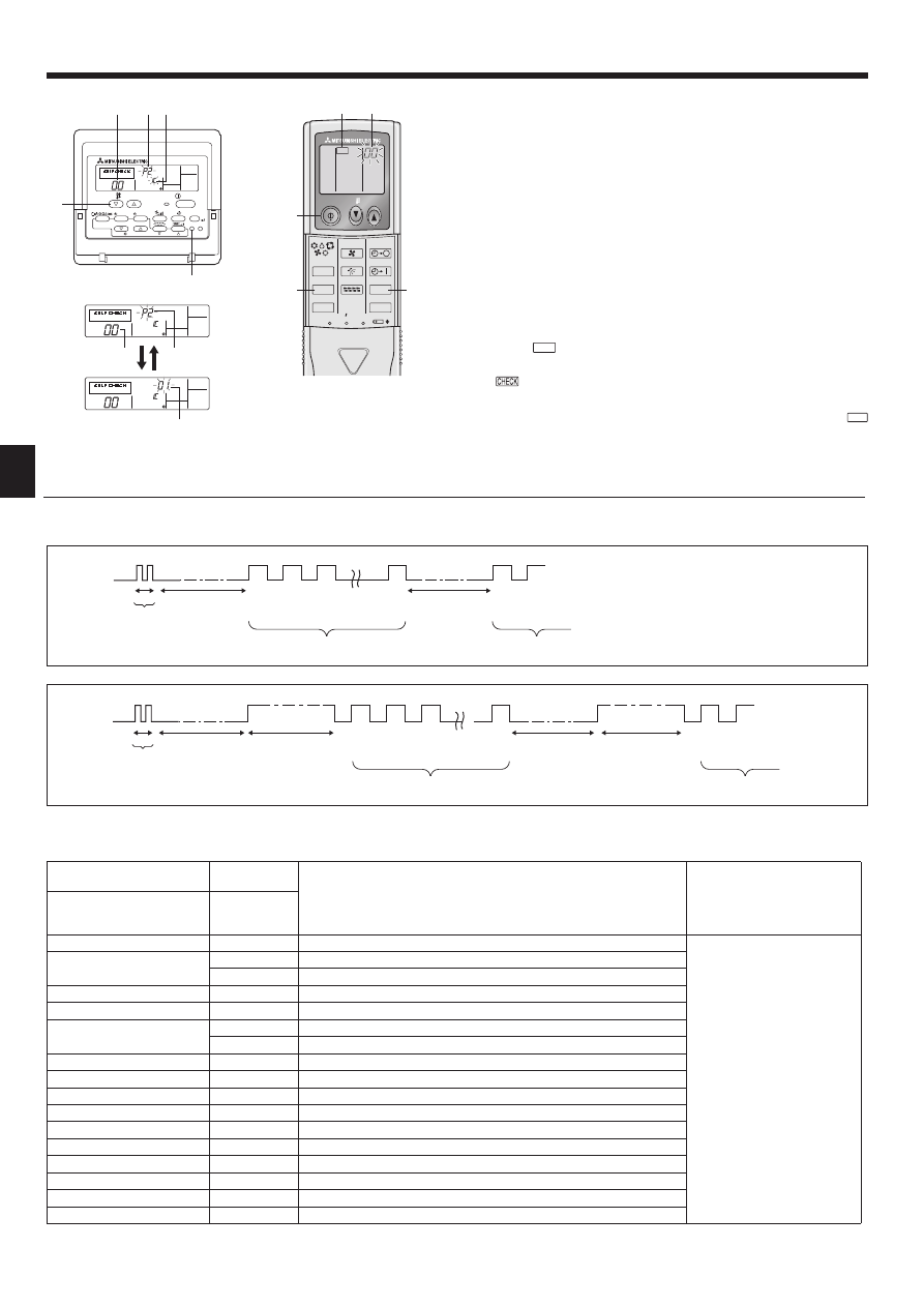
7.3. Self-check
7.3.1. Wired remote controller (Fig. 7-3)
1
Turn on the power.
2
Press the [CHECK] button twice.
3
Set refrigerant address with [TEMP] button if system control is used.
4
Press the [ON/OFF] button to stop the self-check.
A
CHECK button
B
Refrigerant address
C
TEMP. button
D
IC: Indoor unit
OC: Outdoor unit
E
Check code
F
Unit address
7.3.2. Wireless remote controller (Fig. 7-4)
1
Turn on the power.
2
Press the
CHECK
button twice.
(Start this operation from the status of remote controller display turned off.)
A
begins to light.
B
“00” begins to blink.
3
While pointing the remote controller toward the unit’s receiver, press the
h
button. The check code will be indicated by the number of times that the buzzer
sounds from the receiver section and the number of blinks of the operation
lamp.
4
Press the ON/OFF button to stop the self-check.
OPERATION
INDICATOR
lamp blinking
pattern
Beep
Beep
Beep
Beep
Beep
Beep
Beep
Off
Approx. 2.5 sec.
On
Approx. 3 sec.
On
0.5 sec.
On
0.5 sec.
On
0.5 sec.
On
0.5 sec.
Off
Approx. 2.5 sec.
On
Approx. 3 sec.
On
0.5 sec.
On
0.5 sec.
· · · Repeated
Number of blinks/beeps in pattern indicates the check
code in the following table (i.e., n=5 for “U2”)
Number of blinks/beeps in pattern indicates
the check code in the following table
n
th
1
st
2
nd
3
rd
1
st
2
nd
Self-check
starts
(Start signal
received)
Beeper sounds
[Output pattern B]
OPERATION
INDICATOR
lamp blinking
pattern
Beep
Beep
Beep
Beep
Beep
Beep
Beep
Off
Approx. 2.5 sec.
On
0.5 sec.
On
0.5 sec.
On
0.5 sec.
On
0.5 sec.
Off
Approx. 2.5 sec.
On
0.5 sec.
On
0.5 sec.
· · · Repeated
Number of blinks/beeps in pattern indicates the check
code in the following table (i.e., n=5 for “P5”)
Number of blinks/beeps in pattern indicates
the check code in the following table
n
th
1
st
2
nd
3
rd
1
st
2
nd
Self-check
starts
(Start signal
received)
Beeper sounds
01̲RG79D451H01̲EN.indd 12
2008/12/17 13:10:11
13
7. Test run
[Output pattern B] Errors detected by unit other than indoor unit (outdoor unit, etc.)
Wireless remote controller
Wired remote
controller
Symptom
Remark
Beeper sounds/OPERATION
INDICATOR lamp blinks
(Number of times)
Check code
1
E9
Indoor/outdoor unit communication error (Transmitting error) (Outdoor unit)
For details, check the LED
display of the outdoor controller
board.
2
UP
Compressor overcurrent interruption
3
U3, U4
Open/short of outdoor unit thermistors
4
UF
Compressor overcurrent interruption (When compressor locked)
5
U2
Abnormal high discharging temperature/49C worked/insuffi cient refrigerant
6
U1, Ud
Abnormal high pressure (63H worked)/Overheating protection operation
7
U5
Abnormal temperature of heat sink
8
U8
Outdoor unit fan protection stop
9
U6
Compressor overcurrent interruption/Abnormal of power module
10
U7
Abnormality of super heat due to low discharge temperature
11
U9, UH
Abnormality such as overvoltage or voltage shortage and abnormal
synchronous signal to main circuit/Current sensor error
12
—
—
13
—
—
14
Others
Other errors (Refer to the technical manual for the outdoor unit.)
*1. If the beeper does not sound again after the initial 2 beeps to confi rm the self-check start signal was received and the OPERATION INDICATOR lamp does
not come on, there are no error records.
*2. If the beeper sounds 3 times continuously “beep, beep, beep (0.4 + 0.4 + 0.4 sec.)” after the initial 2 beeps to confi rm the self-check start signal was re-
ceived, the specifi ed refrigerant address is incorrect.
• On wireless remote controller
The continuous buzzer sounds from receiving section of indoor unit.
Blink of operation lamp
• On wired remote controller
Check code displayed in the LCD.
• If the unit cannot be operated properly after test run, refer to the following table to fi nd the cause.
Symptom
Cause
Wired remote controller
LED 1, 2 (PCB in outdoor unit
PLEASE WAIT
For about 2 minutes
after power-on
After LED 1, 2 are lighted, LED 2 is turned
off, then only LED 1 is lighted. (Correct
operation)
• For about 2 minutes after power-on, operation of the remote
controller is not possible due to system start-up. (Correct
operation)
PLEASE WAIT ]Error code
Subsequent to about
2 minutes after
power-on
Only LED 1 is lighted. M LED 1, 2 blink.
• Connector for the outdoor unit’s protection device is not con-
nected.
Reverse or open phase wiring for the outdoor unit’s power
terminal block (L1, L2, L3)
Display messages do not appear
even when operation switch is
turned ON
(operation lamp does not light up).
Only LED 1 is lighted. M LED 1 blinks
twice, LED 2 blinks once.
• Incorrect wiring between indoor and outdoor units (incorrect
polarity of S1, S2, S3)
• Remote controller wire short
On the wireless remote controller with condition above, following phenomena take place.
• No signals from the remote controller are accepted.
• Operation lamp is blinking.
• The buzzer makes a short ping sound.
Note:
Operation is not possible for about 30 seconds after cancellation of function selection. (Correct operation)
For description of each LED (LED1, 2, 3) provided on the indoor controller, refer to the following table.
LED 1 (power for microcomputer)
Indicates whether control power is supplied. Make sure that this LED is always lit.
LED 2 (power for remote controller)
Indicates whether power is supplied to the remote controller. This LED lights only in the case of
the indoor unit which is connected to the outdoor unit refrigerant address “0”.
LED 3 (communication between indoor and outdoor units)
Indicates state of communication between the indoor and outdoor units. Make sure that this LED
is always blinking.
01̲RG79D451H01̲EN.indd 13
2008/12/17 13:10:13
14
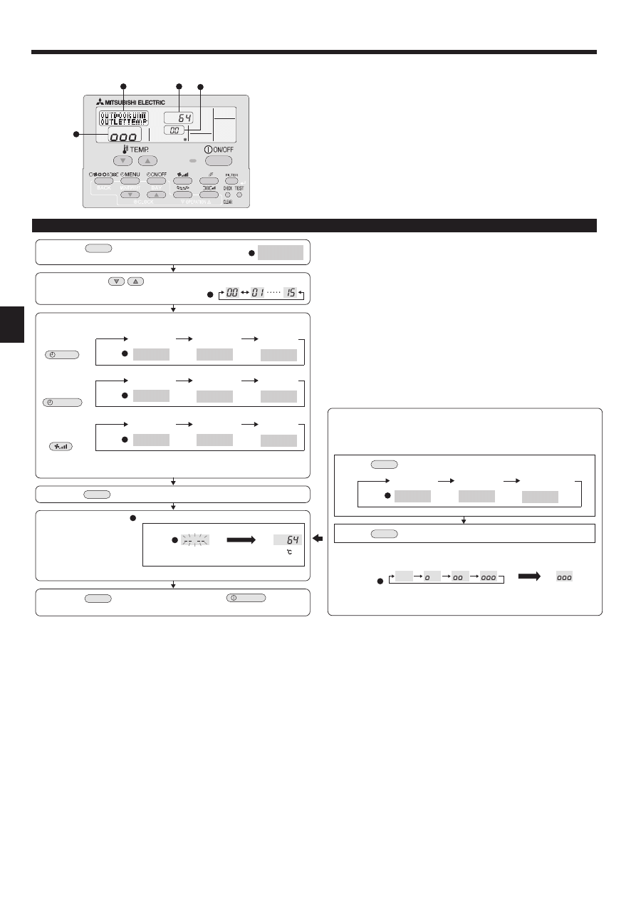
(1) Press the
TEST
button for 3 seconds to
activate the maintenance mode.
(2) Press the TEMP.
buttons to set the refrigerant address.
MAINTENANCE
(3) Select the data you want to display.
MENU
ON/OFF
Compressor
information
COMP ON
x10 HOURS
COMP ON
x100 TIMES
COMP ON
CURRENT (A)
Cumulative
operation time
ON/OFF
number
Operation
current
Display
Display
Display
OUTDOOR UNIT
H•EXC. TEMP
OUTDOOR UNIT
OUTLET TEMP
OUTDOOR UNIT
OUTDOOR TEMP
Heat exchanger
temperature
Comp discharge
temperature
Outdoor ambient
temperature
Display
Outdoor unit
information
INDOOR UNIT
INLET TEMP
INDOOR UNIT
H•EXC. TEMP
INDOOR UNIT
FILTER USE H
Indoor room
temperature
Heat exchanger
temperature
Filter operation
time
Display
Indoor unit
information
* The filter operation time displayed is the number of hours the filter has been
used since the filter reset was performed.
(4) Press the
FILTER
button.
(5) The data is displayed in .
(Airflow temperature display example)
Blinking
Waiting for
response
Approx.
10 sec.
64
* Repeat steps (2) to (5) to check another data.
(6) Press the
TEST
button for 3 seconds or press the
ON/OFF
button to
deactivate the maintenance mode.
Stable operation
Using the maintenance mode, the operation frequency can be fixed and the op-
eration can be stabilized. If the air conditioner is stopped, use the following pro-
cedure to start this operation.
COOL
STABLE MODE
HEAT
STABLE MODE
STABLE MODE
CANCEL
Stable cooling
operation
Stable heating
operation
Stable operation
cancellation
Display
Press the
MODE
button to select the operation mode.
Press the
FILTER
button.
Waiting for
stable operation
Display
Stable
operation
10-20 min.
* You can check the data using steps (3) to (5) of the maintenance mode opera-
tion procedures while waiting for the stable operation.
Display example (Comp discharge temperature 64
˚
C)
Display
PAR-21MAA
B
B
C
C
C
D
D
A
A
A
A
A
A
Maintenance mode operation procedures
8. Easy maintenance function (For PUHZ-(H)RP application only)
By using the maintenance mode, you can display many types of maintenance data
on the remote controller such as the heat exchanger temperature and compressor
current consumption for the indoor and outdoor units.
This function can be used whether the air conditioner is operating or not.
During air conditioner operation, data can be checked during either normal opera-
tion or maintenance mode stable operation.
* This function cannot be used during the test run.
* The availability of this function depends on the connecting outdoor unit. Refer to
the brochures.
01̲RG79D451H01̲EN.indd 14
2008/12/17 13:10:13
Wyszukiwarka
Podobne podstrony:
IM PCA RP50 140KAQ RG79D720H01 Nov 2010
IM PKA RP60 100KAL RG79D349H01 Jul 2009
IM PCA RP50 140GA PCH P GAH BG79U614H02 2006
IM PKFY P32 50VHM E RG79D439H03 Aug 2009
IM PCFY P40 125VKM E RG79D452H01 GB 01 2009
IM PUMY P100 125 140YHMB BG79U713H05 Jul 2009
IM PCA RP HA BG79U617H01 2005
IM PFAV P250 900VM E WT05474X02 Oct 2009
IM PCA RP2 6GA BG79U334H01 Aug 2004
BWE0630A PartsList PAC YT40ANRA E Jul 2009
IM PAC SE51CRB WT03594X05 GB Aug 2009
IM PCA RP GA BG79U614H01 2005
IM PEA RP200 500GA WT05126X03 Aug 2009
IM CMY Q100VBK WT05688X01 GB Aug 2009
Biogasanlagen im EEG 2009
IM jednolity tekst 2009
2009 4 JUL New Concepts in Diagnostic Radiology
ZESPÓŁ SZKÓŁ PONADGIMNAZJALNYCH NR l IM, 12.PRACA W SZKOLE, ZSG NR 1 2008-2009
więcej podobnych podstron