
26-1
Exhaust system components,
removing and installing
Note:
After performing repairs on the exhaust system,
ensure that the system is not under stress, and
that it has sufficient clearance from the body. If
necessary, loosen the double clamps and align
the muffler and exhaust pipe so sufficient
clearance is maintained to the body while the
support rings are evenly loaded.
When performing repairs, always replace self-
locking nuts.
Catalyst, checking
Page 26-18
26-2
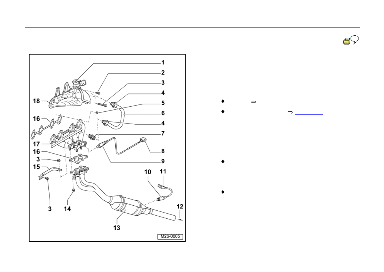
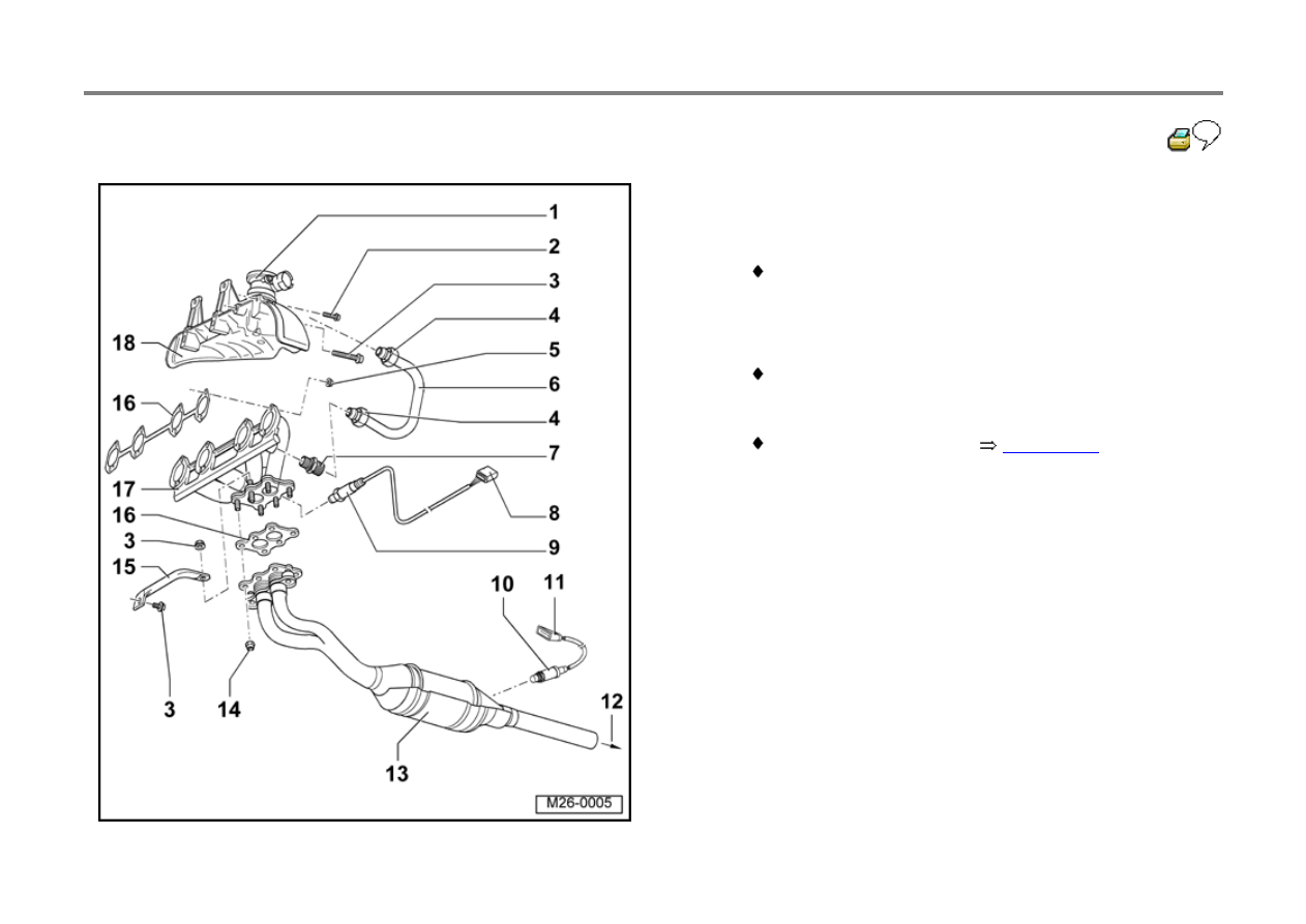
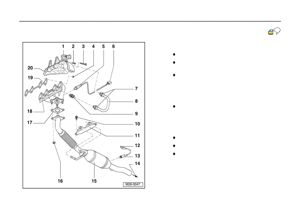
Exhaust manifold, front exhaust pipe and catalyst
with attachments
Engine code AEG
1 - Combi-valve
Checking
Page 26-28
Removing and installing:
Page 26-39
2 - 10 Nm (7 ft lb)
3 - 25 Nm (18 ft lb)
4 - 30 Nm (22 ft lb)
5 - 25 Nm (18 ft lb)
Always replace
6 - Connecting pipe
7 - Union
35 Nm (26 ft lb)
26-3
Repair Manual, 2.0 Liter 4-Cyl. 2V Fuel Injection &
Ignition, Engine Code(s): AEG, Repair Group 24
8 - 4-pin harness connector
Black
for Oxygen sensor 1 G39 and Oxygen sensor
heating
Terminals 3 and 4 gold plated
9 - Oxygen sensor 1 -G39- (in front of catalyst)
50 Nm (37 ft lb)
Only coat threads using anti-seize compound not
containing silicone and marked "safe for oxygen
sensors"; do not allow compound to enter slots on
sensor body
Remove and install using 3337
Checking:
26-4
Repair Manual, 2.0 Liter 4-Cyl. 2V Fuel Injection &
Ignition, Engine Code(s): AEG, Repair Group 24
10 - Oxygen sensor 2 -G130- (behind catalyst)
50 Nm (37 ft lb)
Only coat threads using anti-seize compound not
containing silicone and marked "safe for oxygen
sensors"; do not allow compound to enter slots on
sensor body
Remove and install with 3337
Checking:
11 - 4-pin harness connector
Brown
Terminals 3 and 4 gold
for Oxygen sensor 2 G130 and Oxygen sensor
heater
12 - To center muffler
26-5
13 - Front exhaust pipe with catalyst
14 - 40 Nm (30 ft lb)
Always replace
15 - Support
16 - Gasket
Always replace
17 - Exhaust manifold
Removing and installing:
Page 26-15
18 - Warm air collector plate

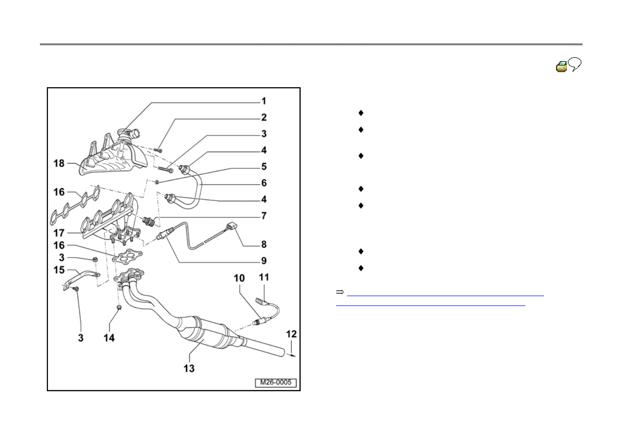
26-6
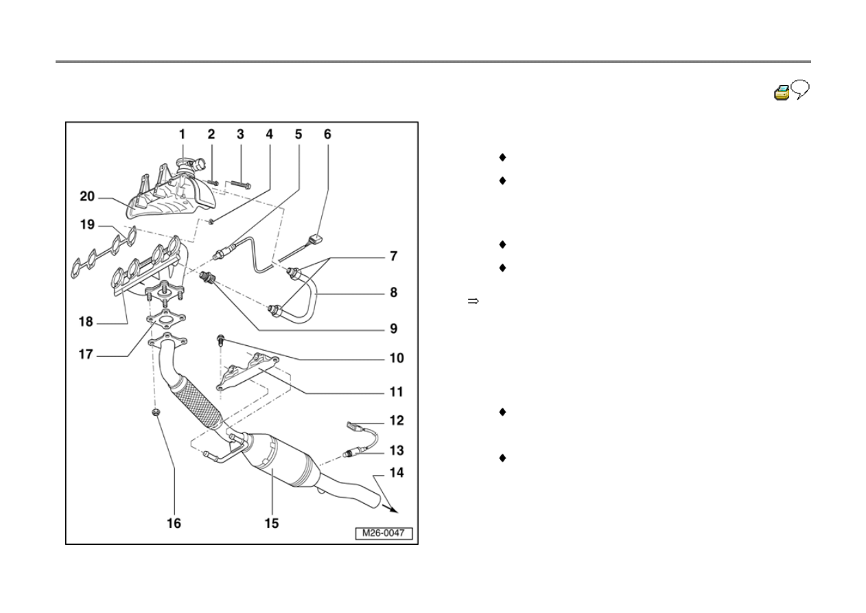
Engine codes AVH, AZG
Repair Manual, 2.0 Liter 4-Cyl. 2V Fuel Injection &
Ignition, Engine Code(s): AVH, Repair Group 24
1 - Combi-valve
Removing and installing:
Page 26-39
2 - 10 Nm (7 ft lb)
3 - 25 Nm (18 ft lb)
4 - 25 Nm (18 ft lb)
Always replace
5 - Oxygen sensor 1 -G39- (in front of catalyst)
50 Nm (37 ft lb)
Only coat threads using anti-seize compound not
containing silicone and marked "safe for oxygen
sensors"; do not allow compound to enter slots on
sensor body
Remove and install using 3337
Checking:
26-7
6 - 4-pin harness connector
Black
for Oxygen sensor 1 G39 and Oxygen sensor
heating
Terminals 3 and 4 gold plated
7 - 30 Nm (22 ft lb)
8 - Connecting pipe
9 - Union
35 Nm (26 ft lb)
10 - 25 Nm (18 ft lb)
11 - Mounting
12 - 4-pin harness connector
Brown
Terminals 3 and 4 gold
for Oxygen sensor 2 -G130- and Oxygen sensor
heater
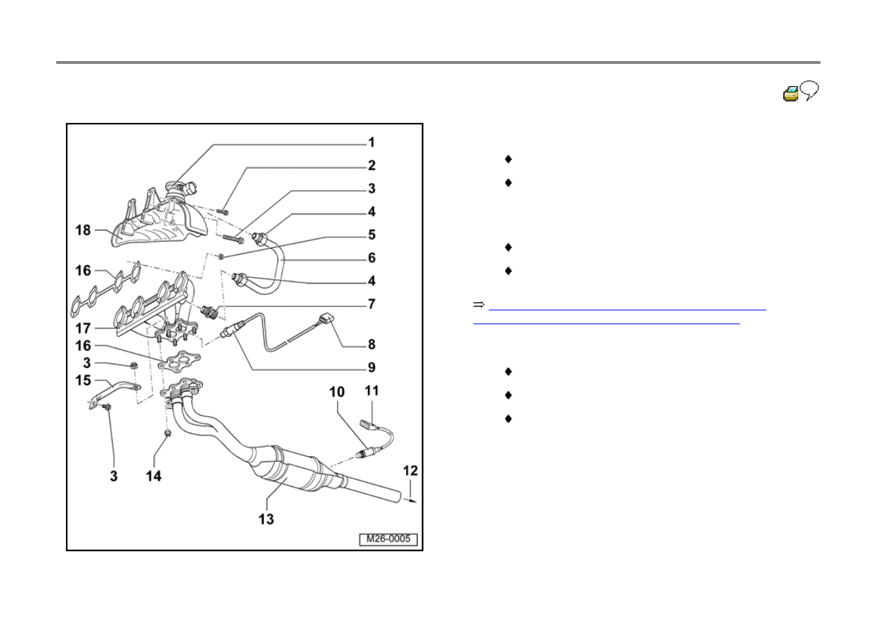
26-8
Repair Manual, 2.0 Liter 4-Cyl. 2V Fuel Injection &
Ignition, Engine Code(s): AVH, Repair Group 24
13 - Oxygen sensor 2 -G130- (behind catalyst)
50 Nm (37 ft lb)
Only coat threads using anti-seize compound not
containing silicone and marked "safe for oxygen
sensors"; do not allow compound to enter slots on
sensor body
Remove and install with 3337
Checking:
14 - To center muffler
15 - Front exhaust pipe with catalyst
16 - 40 Nm (30 ft lb)
Always replace
17 - Gasket
Always replace
26-9
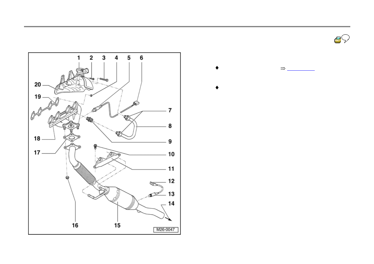
18 - Exhaust manifold
Removing and installing:
Page 26-15
19 - Gasket
Always replace
20 - Warm air collector plate
26-10
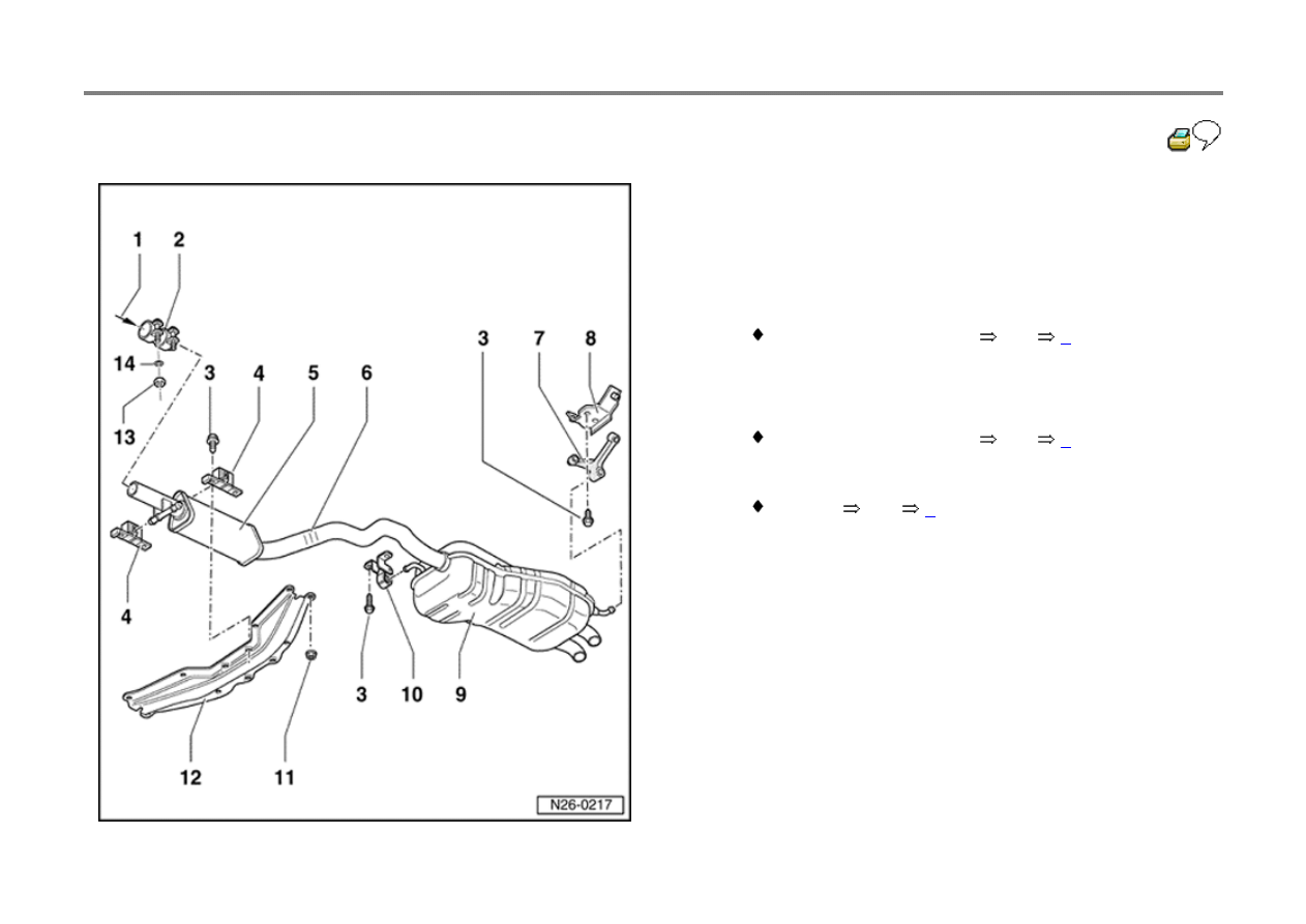
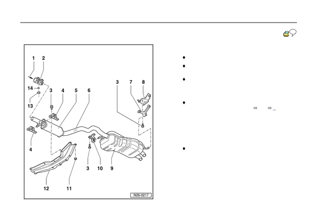
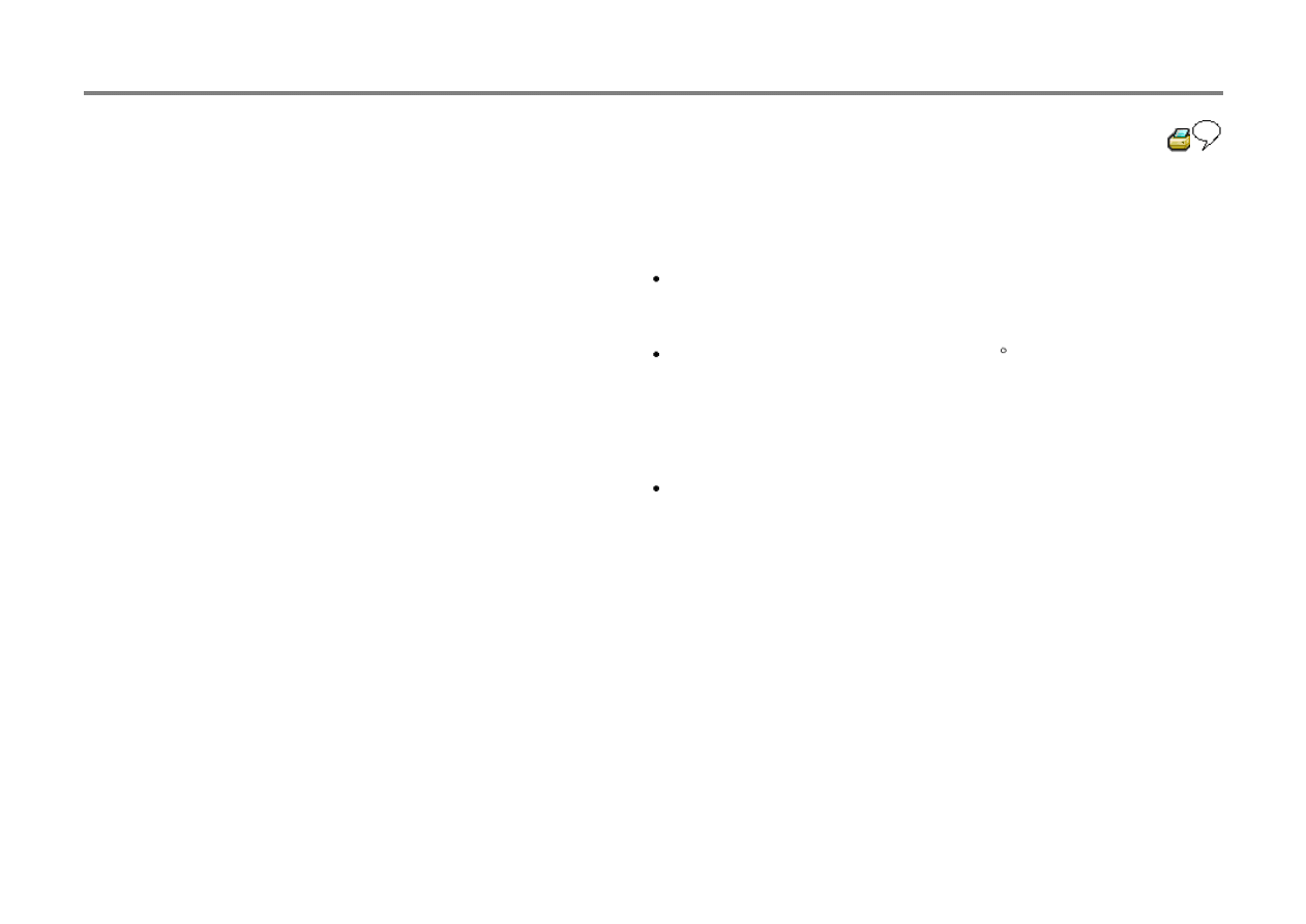
Muffler system with mountings, component
overview
1 - from Catalyst
2 - Double clamp
Note installation position
Fig.
1
3 - 25 Nm (18 ft lb)
4 - Mounting
Note installation position
Fig.
2
5 - Center muffler
Aligning
Fig.
4
26-11
6 - Separation point
For repairing
Exhaust pipe is marked with three indentations
around circumference
Center and rear mufflers are installed as a single
welded component in production. Center and rear
mufflers can be obtained individually with double
clamp as spare parts.
Saw through connecting pipe (at right angles) at
separating point using body saw
Fig.
3
7 - Mounting
8 - Bracket
9 - Rear muffler
10 - Mounting
With retaining ring

26-12
11 - 20 Nm (15 ft lb)
12 - Tunnel bridge
13 - 40 Nm (30 ft lb)
14 - Washer
26-13
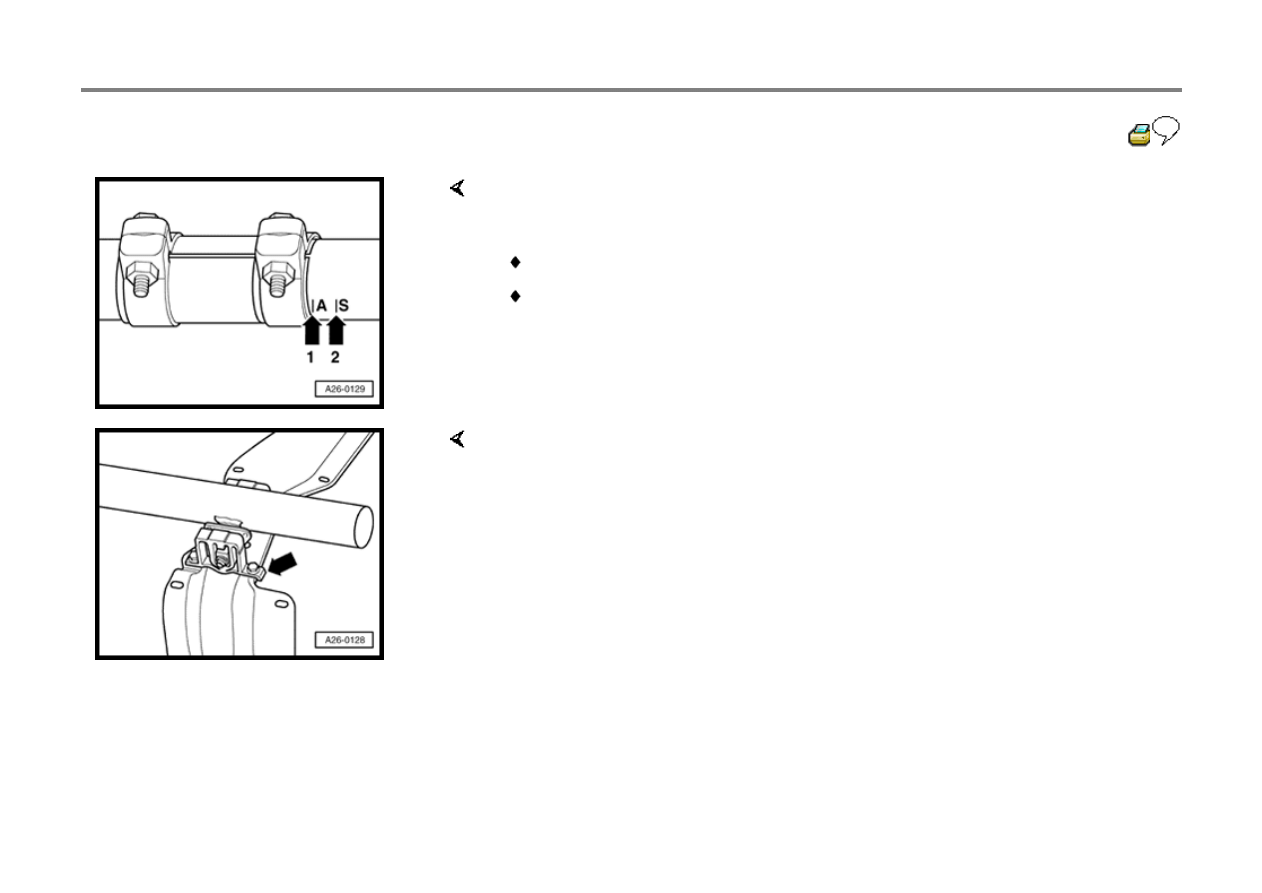
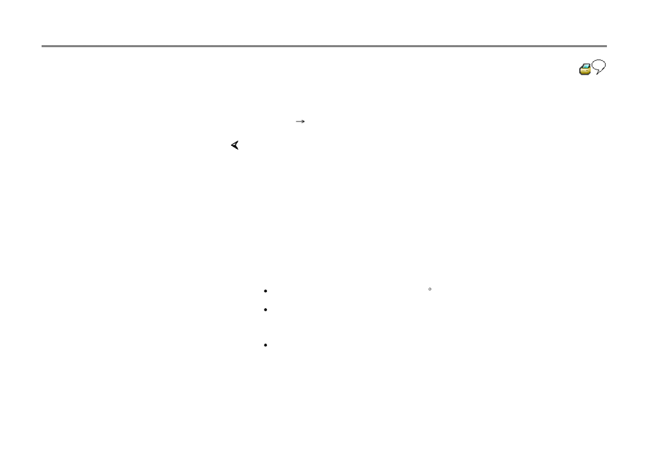
Fig. 1
Double clamp installing position, checking
- Position dual clamp with 5 mm distance for mark A (arrow 1).
Mark A (arrow 1) for vehicles with automatic transmission
Mark S (arrow 2) for vehicles with manual transmission
Fig. 2
Installed position of mount
- Angled side on foot of mount (arrow) points forward.
26-14
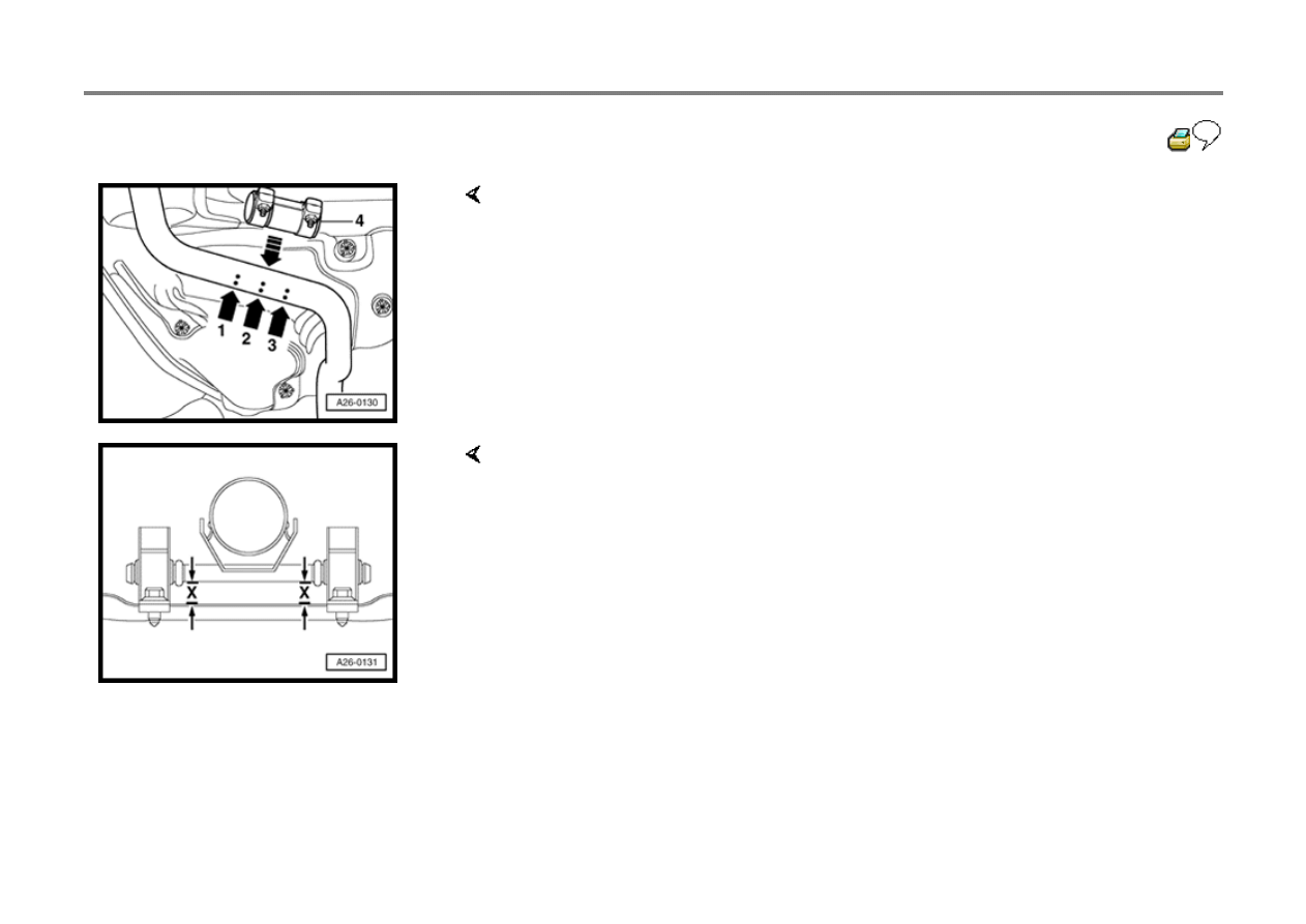
Fig. 3
Separation point on exhaust pipe
- Separate exhaust pipe (at right angles) at separation point (arrow 2).
- Position dual clamp -4- at installation (arrows 1 and 3).
Tightening torque: 40 Nm (30 ft lb)
Fig. 4
Aligning center muffler tension free
- Mount for center muffler must be parallel to tunnel bridge (dimension -x- left and
right is identical)
26-15
Exhaust manifold, removing and
installing
Special tools
Removing
Repair Manual, 2.0 Liter 4-Cyl. 2V Fuel Injection & Ignition, Engine Code(s):
AEG, Repair Group 24
Repair Manual, 2.0 Liter 4-Cyl. 2V Fuel Injection & Ignition, Engine Code(s):
AVH, Repair Group 24
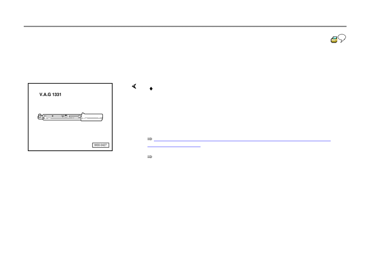
V.A.G 1331 Torque wrench 5 to 50 Nm (3.7 to 37 ft lb), or equivalent
- Remove engine cover.
- Remove intake hose:
- Remove pressure and vacuum hoses from combi-valve.
- Remove connector pipe from combi-valve and exhaust manifold.
- Remove warm air collector plate.
- Remove right hand inner CV joint protective cover.
26-16
- Disconnect right drive shaft from transmission:
Repair Manual, Suspension, Wheels,
Steering, Repair Group 40
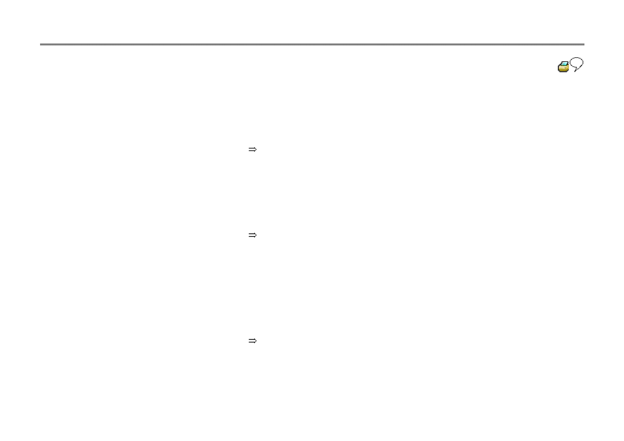
Installing
Installation is the reverse of removal. Note the following:
Repair Manual, 2.0 Liter 4-Cyl. 2V Fuel Injection & Ignition, Engine Code(s):
AEG, Repair Group 01
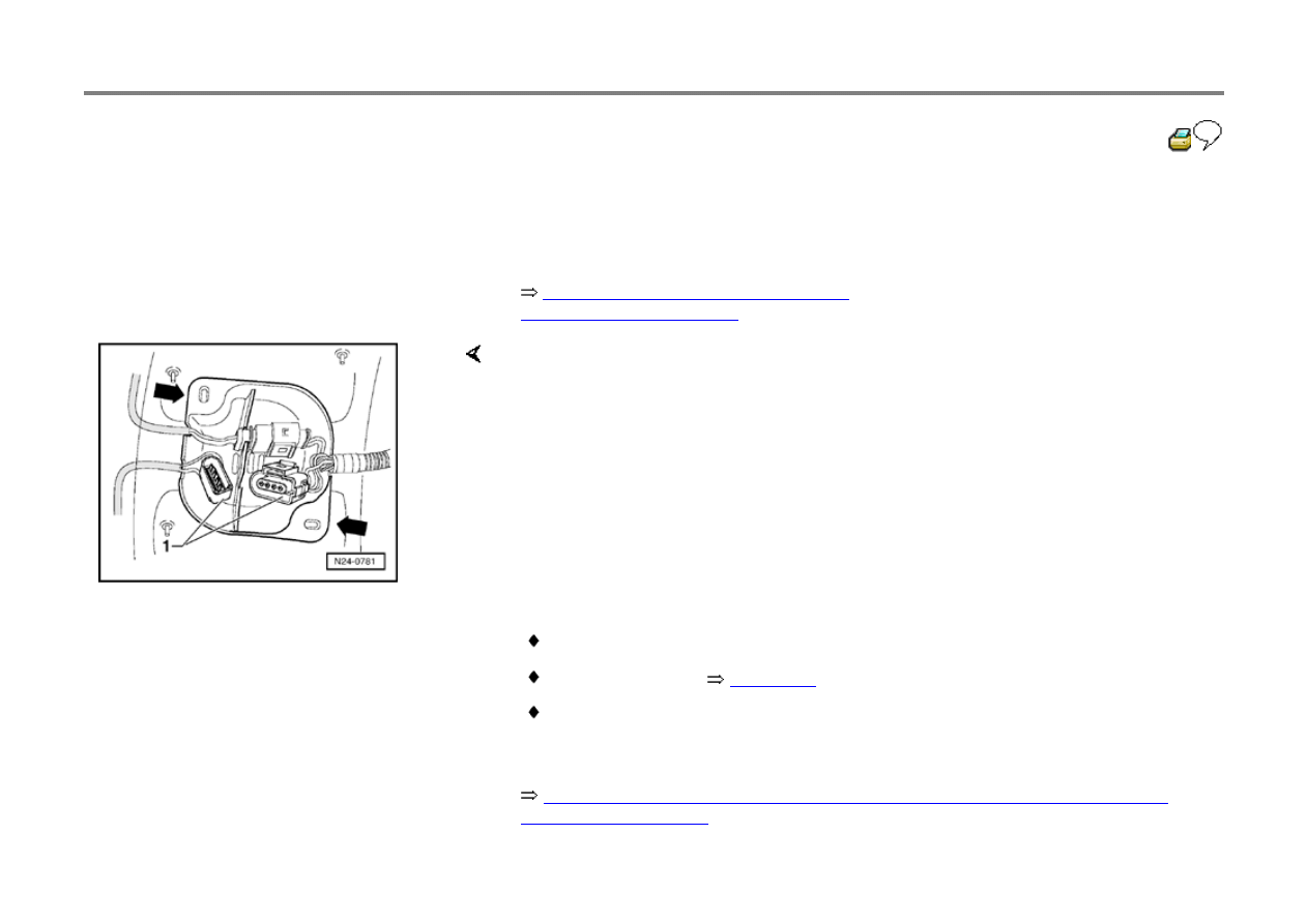
- Remove protective cover (arrows) and disconnect 4-pin connector (black) -1- for
oxygen sensor 1 -G39-.
- Remove oxygen sensor 1 -G39- wiring retainers.
- Remove front exhaust pipe with catalyst and bracket.
- Remove exhaust manifold by removing lower nuts from below and upper nuts
from above.
Always replace all seals and self-locking nuts
Tightening torques
Page 26-2
.
Drive shaft to transmission: 40 Nm (30 ft lb)
- Check Diagnostic Trouble Code (DTC) memory:

Repair Manual, 2.0 Liter 4-Cyl. 2V Fuel Injection & Ignition, Engine Code(s):
AVH, Repair Group 01
26-17
- Display Readiness code:
Repair Manual, 2.0 Liter 4-Cyl. 2V Fuel
Injection & Ignition, Engine Code(s): AEG, Repair
Group 01
Repair Manual, 2.0 Liter 4-Cyl. 2V Fuel
Injection & Ignition, Engine Code(s): AVH, Repair
Group 01
- Readiness code must be reset if ECM is subject
to low voltage with ignition ON or if DTC memory
is erased.
Repair Manual, 2.0 Liter 4-Cyl. 2V Fuel
Injection & Ignition, Engine Code(s): AEG, Repair
Group 01
Repair Manual, 2.0 Liter 4-Cyl. 2V Fuel
Injection & Ignition, Engine Code(s): AVH, Repair
Group 01
26-18
Three Way Catalyst, checking
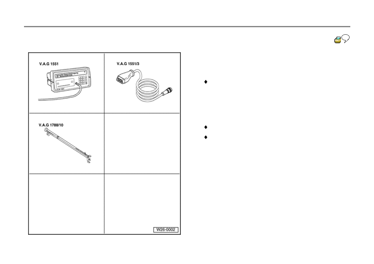
Special tools
Note:
V.A.G 1552 Scan Tool can be used instead of the V.A.G
1551; however, the V.A.G 1552 has no printer.
V.A.G 1551 Scan Tool
V.A.G 1551/3 Adapter cable
V.A.G 1788/10 RPM adjuster (only with engine code
AEG)
26-19
Test sequence
- Connect V.A.G 1551/1552) Scan Tool:
Repair Manual, 2.0 Liter 4-Cyl. 2V Fuel
Injection & Ignition, Engine Code(s): AEG, Repair
Group 01
Repair Manual, 2.0 Liter 4-Cyl. 2V Fuel
Injection & Ignition, Engine Code(s): AVH, Repair
Group 01
- Start engine and let idle.
- Press 0 and 1 buttons to select Address Word
01: "engine electronics".
Rapid data transfer
HELP
Select function XX
Display will appear as shown
- Press 0 and 4 buttons to select Function 04: "Basic setting".
- Press Q button to enter input.
Introduce basic setting
HELP
Display will appear as shown

Input display group number XXX
- Press 0, 4 and 6 buttons to select "Display group 46".
- Press Q button to enter input.
Basic setting 46
1
2
3
4
Display will appear as shown (1 to 4
Display zones)
Engine code AEG
- Set engine speed with V.A.G 1788/10 speed adjuster between 2800 and 3200
rpm.
26-20
- Maintain engine speed between 2800 and 3200
rpm.
Value in display zone 4 changes from "Test
OFF" to "Test ON".
Value in display zone 2 minimum 352.0 C.
- Continue maintaining engine speed between
2800 and 3200 rpm.
Display zone 4 changes to "Cat. B1 OK".
Note:
Catalyst diagnostic lasts about 100 seconds. If
test does not complete after 150 seconds, adjust
engine speed within range of 2800 to 3200 rpm.
- Remove V.A.G 1788/10 engine speed adjuster
from throttle pedal.
If "Cat. B1 not OK" appears in display zone 4:
- Check Diagnostic Trouble Code (DTC)
memory:

Repair Manual, 2.0 Liter 4-Cyl. 2V Fuel
Injection & Ignition, Engine Code(s): AEG, Repair
Group 01
- Display Readiness code:
Repair Manual, 2.0 Liter 4-Cyl. 2V Fuel
Injection & Ignition, Engine Code(s): AEG, Repair
Group 01
- Readiness code must be reset if ECM is subject
to low voltage with ignition ON or if DTC memory
is erased.
Repair Manual, 2.0 Liter 4-Cyl. 2V Fuel
Injection & Ignition, Engine Code(s): AEG, Repair
Group 01
26-21
If specification "Cat B1 OK" obtained:
- Press
button.
Rapid data transfer
HELP
Select function XX
Display will appear as shown
Engine codes AVH, AZG
Note:
This process may require several minutes time.
- Press 0 and 6 buttons to select Function 06: "End transfer".
- Press Q button to enter input.
- Press brake pedal down and hold.
- Push accelerator down to WOT tip-in. Engine control module turns engine speed
down to 2300 rpm.
- Let engine run with increased engine speed.
Value in display zone 2 minimum 540 C.
Value in display zone 4 changes from "Test OFF" to "Test ON".
- Let engine run with increased engine speed.
Display zone 4 changes to "Cat. B1 OK".

If "Cat. B1 not OK" appears in display zone 4:
26-22
- Check Diagnostic Trouble Code (DTC)
memory:
Repair Manual, 2.0 Liter 4-Cyl. 2V Fuel
Injection & Ignition, Engine Code(s): AVH, Repair
Group 01
- Display Readiness code:
Repair Manual, 2.0 Liter 4-Cyl. 2V Fuel
Injection & Ignition, Engine Code(s): AVH, Repair
Group 01
- Readiness code must be reset if ECM is subject
to low voltage with ignition ON or if DTC memory
is erased.
Repair Manual, 2.0 Liter 4-Cyl. 2V Fuel
Injection & Ignition, Engine Code(s): AVH, Repair
Group 01
If specification "Cat B1 OK" obtained:

- Press
button.
Rapid data transfer
HELP
Select function XX
Display will appear as shown
- Press 0 and 6 buttons to select Function 06: "End transfer".
- Press Q button to enter input.
Wyszukiwarka
Podobne podstrony:
Proj syst log wykl 6
syst tr 1 (2)TM 01 03)13
Program Progr Syst i Wspolb2011
pomoc SYST[1].INF, Szkoła
Cechy org jako syst społ
azg cel 07
BO ZAO g4
KNOCHE GRUBER SG G4
HEX?ficiency Exhaust
Instrukcja drgania 1, Automatyka i robotyka air pwr, VI SEMESTR, Syst. monit. i diagn. w przem, Mate
(15)Syst.rz-d. Cz. II, Prawne podstawy bezpieczeństwa państwa
analogowe sprawko cw B, Automatyka i robotyka air pwr, VI SEMESTR, Analogowe i cyfr. syst. pom
Powtóreczka do kolokwium z syst podatkowych
bledy syst przyp, BS I P, Laboratorium Podstaw Miernictwa
struktury inter a uklady i syst spol -1 19, 19
bledy syst przyp, M BLMET, B˙˙d metody
więcej podobnych podstron