
SECTION 2
POSITION OF CONNECTORS AND GROUNDS
2–2
W
POSITION OF CONNECTORS AND GROUNDS
1. CONNECTOR, GROUND AND SPLICE PACK INFORMATION
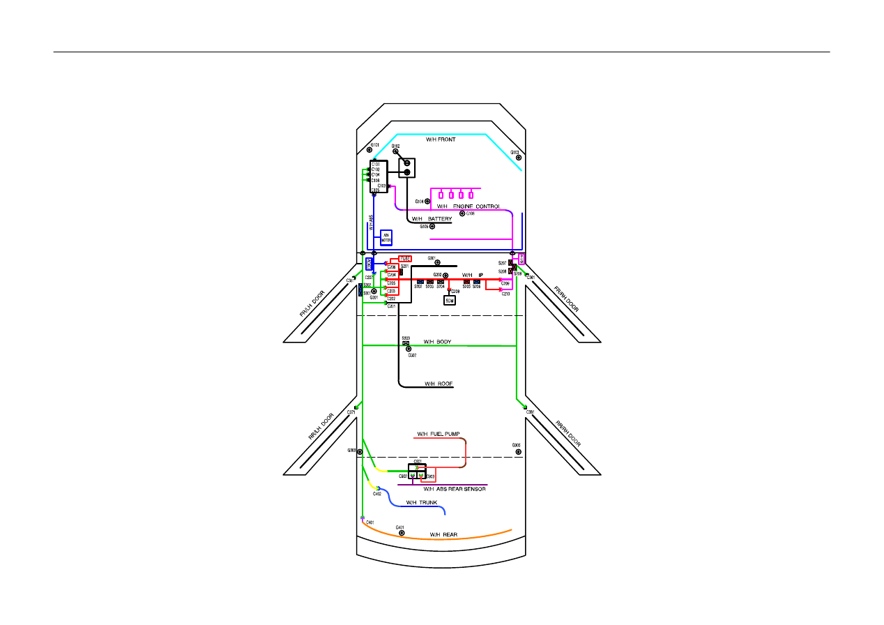
1) WIRING HARNESS & GROUND & SPLICE PACK LOCATION

POSITION OF CONNECTORS AND GROUNDS
W
2–3
2) CONNECTOR
Connector
Number
Terminal
Number
Color
Connecting Wiring Harness
Connector Position
C101
68
Gray
Engine Room Fuse Box
Ĉ
Front
Engine Room Fuse Box
C102
68
Brown
Engine Room Fuse Box
Ĉ
Body
Engine Room Fuse Box
C103
68
Black
Engine Room Fuse Box
Ĉ
Engine
Control
Engine Room Fuse Box
C104
2
Gray
Engine Room Fuse Box
Ĉ
Body
Engine Room Fuse Box
C105
2
Black
Engine Room Fuse Box
Ĉ
ABS
Engine Room Fuse Box
C106
2
Green
Engine Room Fuse Box
Ĉ
Body
Engine Room Fuse Box
C201
13
White
Body
Ĉ
Roof
Behind Driver Left Kick Panel
C202
12
White
I/P
Ĉ
Body(Remote Control)
Next to Driver Leg Room Connector Holder
C203
15
White
I.P
Ĉ
Body
Left Driver Leg Room Connector Holder
C204
22
Yellow
I.P
Ĉ
Body
Center Driver Leg Room Connector Holder
C205
20
Colorless
I.P
Ĉ
Body
Right Driver Leg Room Connector Holder
C206
11
White
I/P
Ĉ
ABS
Upper Driver Leg Room
C207
4
White
Body
Ĉ
ABS
Upper Driver Leg Room
C208
6
White
I/P
Ĉ
Air Bag
Behind Car Audio
C209
20
Colorless
I/P
Ĉ
Engine Control
Upper Co–driver Right Kick Panel
C210
10
White
I/P
Ĉ
Engine Control
Upper Co–driver Right Kick Panel
C351
29
White
Body
Ĉ
Driver Door
Inside Left A Pillar
C361
29
White
Body
Ĉ
Co–driver Door
Inside Right A Pillar
C371
8
Colorless
Body
Ĉ
Rear Left Door
Inside Left B Pillar
C381
8
Colorless
Body
Ĉ
Rear Right Door
Inside Right B Pillar
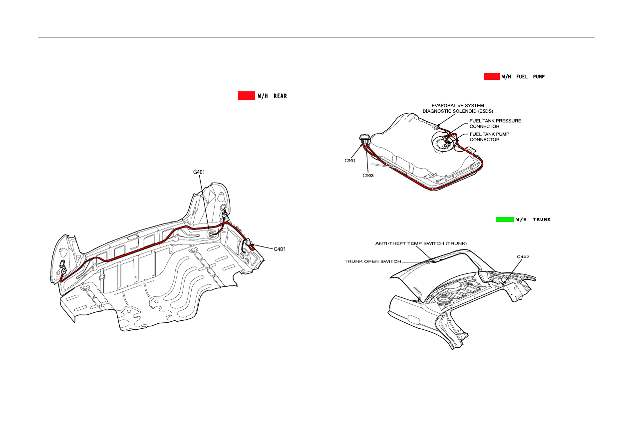
C401
8
White
Body
Ĉ
Rear
Upper Trunk Room Left Wheel House
C402
4
White
Body
Ĉ
Trunk/Tailgate(H/B, S/W)
Upper Trunk Room Left
C403
3
White
Body
Ĉ
Tailgate (H/B)
Upper Trunk Room Left
C404
6
White
Body
Ĉ
Tailgate (Station Wagon)
Upper Trunk Room Left
C901
8
Black
Body
Ĉ
Fuel Pump
Under Body Near Trunk
C902
4
Black
Body
Ĉ
ABS Rear Speed Sensor
Under Body Near Trunk
C903
4
Black
Body
Ĉ
Fuel Pump
Under Body Near Trunk
3) GROUND
Ground Number
Wiring Harness
Ground Position
G101
W/H Front
Left Fender in Front of Fuse Box
G102
Battery & ABS
Between Battery and Fuse Box
G103
W/H Front
Engine Room Right Fender (Splice Pack)
G104
Engine Control
Cylinder Head Next to #4 Intake Manifold
G105
Battery
Next to Starter Motor
G106
Engine Control
Engine Block Below #2 Intake Manifold
G201
I/P & Body
Behind Driver Left Kick Panel
G202
I.P
Right Side of I/P
G301
Roof
Next to Room Lamp
G302
Body
Below Driver Seat
G303
Body
Left Rear Seat Back
G305
Body
Passenger Room Right C Pillar
G401
Rear
Trunk Room End Panel
G402
Tailgate
Upper Luggage Left (H/B, S/W)
4) SPLICE PACK
Splice Pack
Number
Color
Wiring Harness
Splice Pack Position
S201
Brown
I.P
Upper Driver Leg Room
S202
Blue
I.P
Upper Driver Leg Room
S203
Brown
I.P
Upper Driver Leg Room
S204
Gray
I.P
Upper Driver Leg Room
S205
Red
I.P
Left Behind Glove Box
S206
Blue
I/P
Right Behind Glove Box
S207
Blue
Engine Control
Behind Co–driver Right Kick Panel
S208
White
Engine Control
Behind Co–driver Right Kick Panel
S301
Blue
Body
Behind Driver Left Kick Panel
S302
Blue
Body
Behind Driver Left Kick Panel
S303
Black
Body
Below Driver Seat
2–4
W
POSITION OF CONNECTORS AND GROUNDS
2. WIRING HARNESS & CONNECTOR & GROUND LOCATION
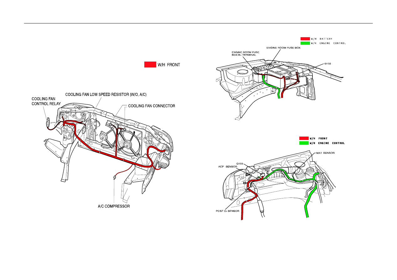
1) W/H FRONT, FRONT BUMPER
POSITION OF CONNECTORS AND GROUNDS
W
2–5
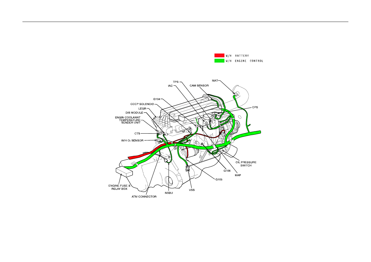
2) ENGINE CONTROL, BATTERY
S
2.0 DOHC ENGINE
2–6
W
POSITION OF CONNECTORS AND GROUNDS
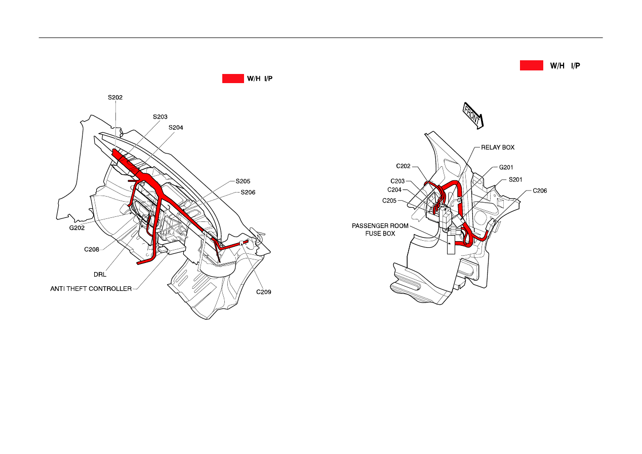
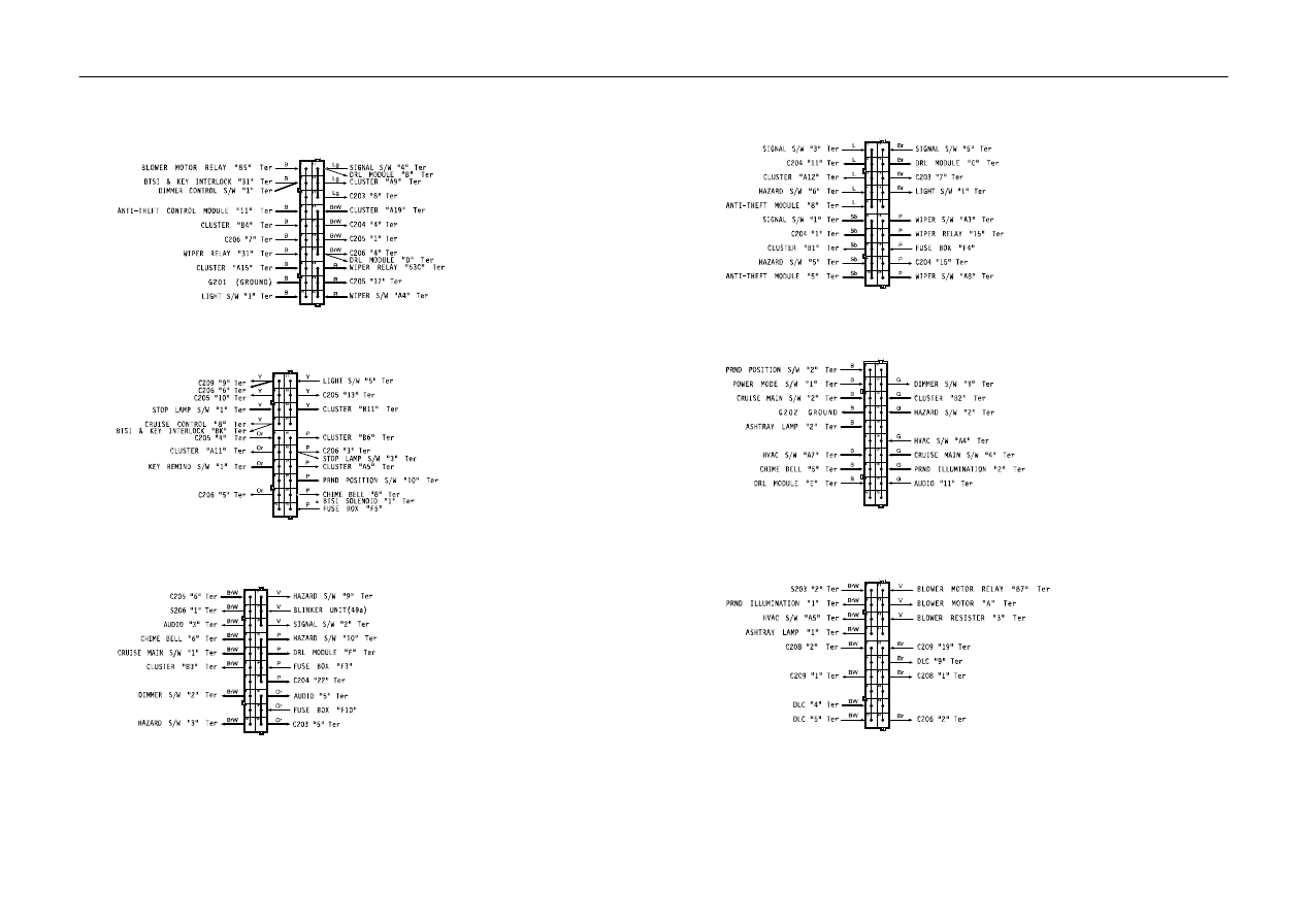
3) INSTRUMENT PANEL INSIDE
POSITION OF CONNECTORS AND GROUNDS
W
2–7
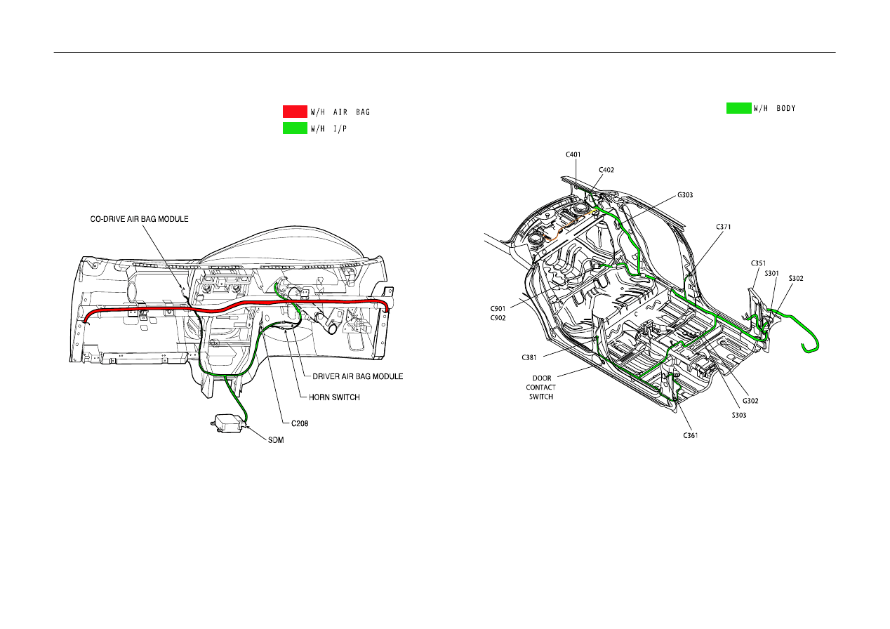
4) AIR BAG, INSTRUMENT PANEL
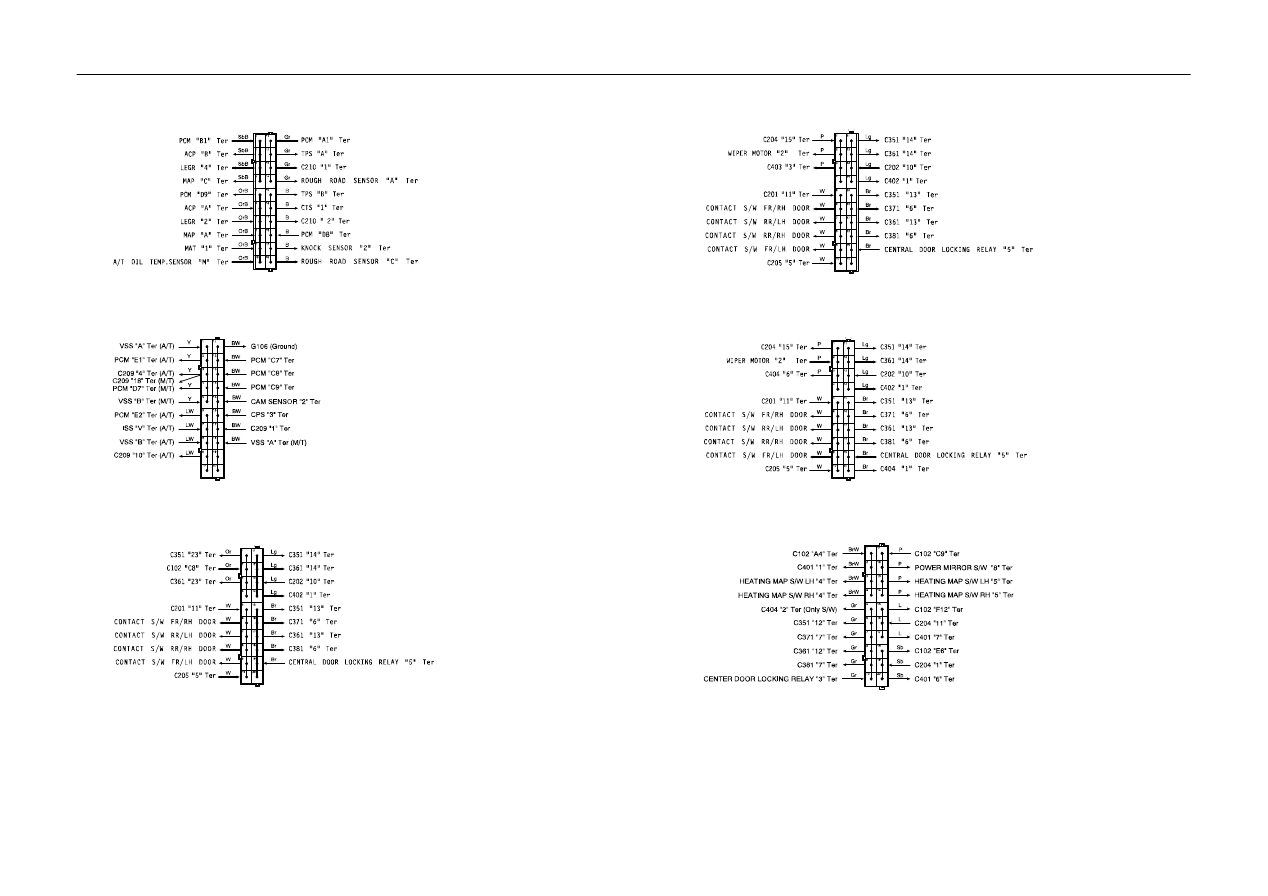
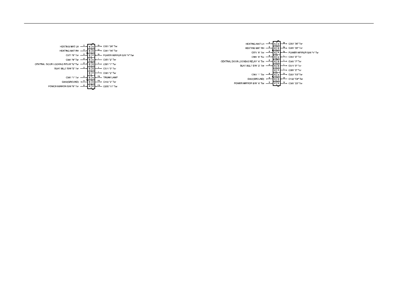
5) BODY
2–8
W
POSITION OF CONNECTORS AND GROUNDS
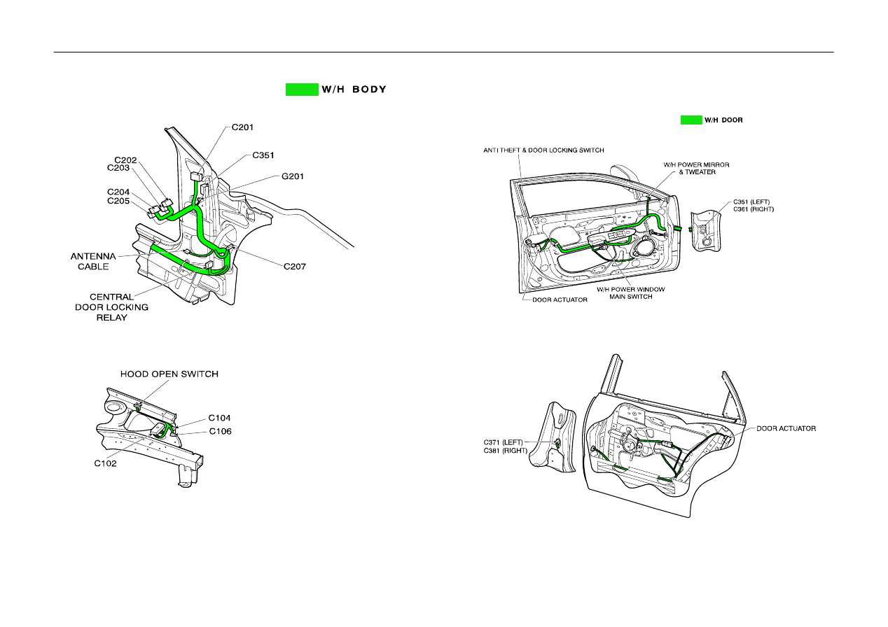
6) W/H DOOR
1. Front Door
2. Rear Door
POSITION OF CONNECTORS AND GROUNDS
W
2–9
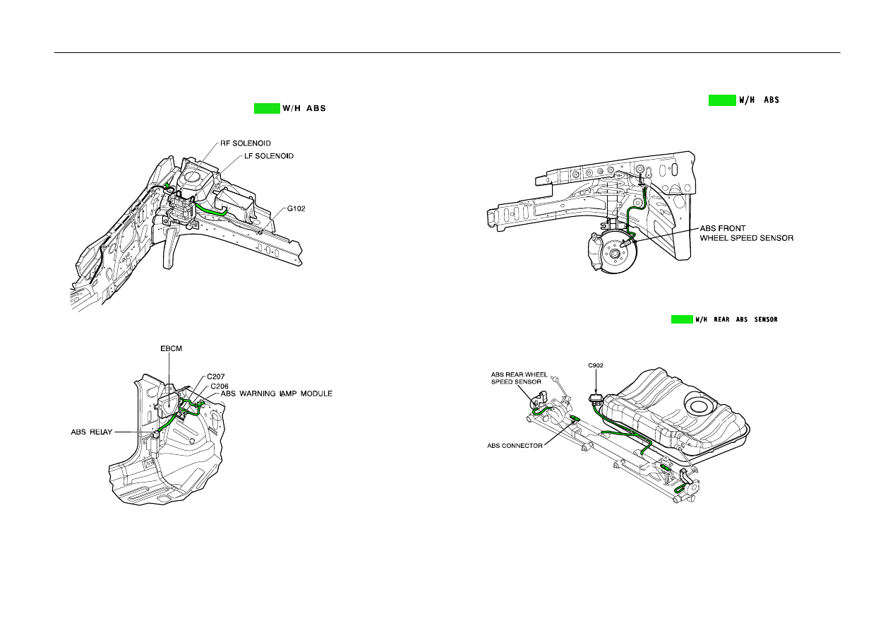
7) ABS WHEEL SPEED SENSOR
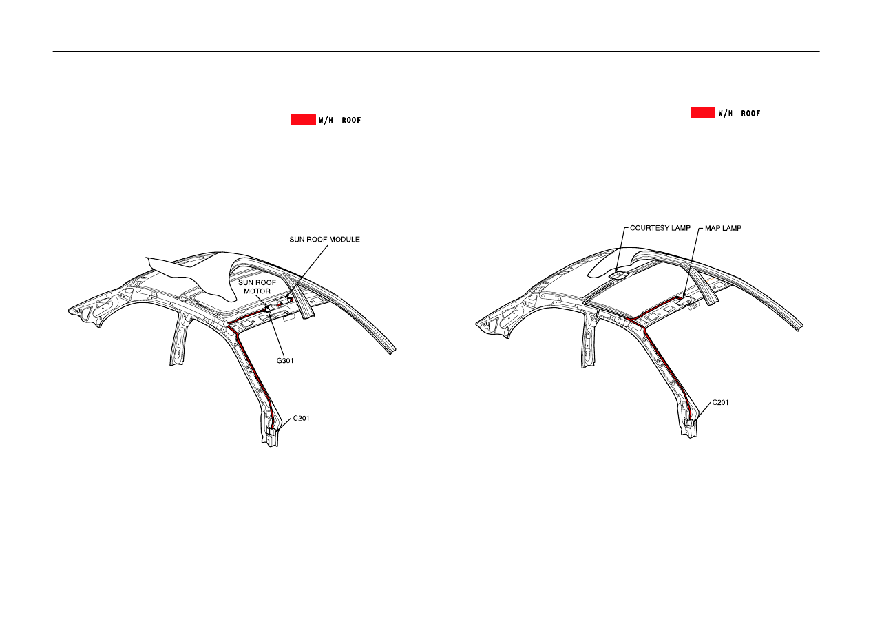
1. With Sun Roof
2. Without Sun Roof
2–10
W
POSITION OF CONNECTORS AND GROUNDS
8) ABS MODULE & WHEEL SPEED SENSOR
POSITION OF CONNECTORS AND GROUNDS
W
2–11
9) REAR
10) FUEL TANK, TRUNK LID
2–12
W
POSITION OF CONNECTORS AND GROUNDS
11) SPLICE PACK
S201 (BROWN)
S202 (BLUE)
S203 (BROWN)
S204 (GRAY)
S205 (RED)
S206 (BLUE)
POSITION OF CONNECTORS AND GROUNDS
W
2–13
S207 (BLUE)
S208 (WHITE)
S301 (BLUE), N/B
S301 (BLUE), H/B
S301 (BLUE), S/W
S302 (BLACK)
2–14
W
POSITION OF CONNECTORS AND GROUNDS
S303 (BLACK)
Ĉ
N/B & H/B
S303 (BLACK)
Ĉ
S/W
Wyszukiwarka
Podobne podstrony:
British Patent 14,550 Improvements relating to the Insulation of Electric Conductors
British Patent 14,579 Improvements in and relating to the Transmission of Electrical Energy
Dick Do Androids Dream of Electric Sheep
00 Mechatronics of Electrostatic Microactuators for HD
End of the book TestB Units 1 14
Connector Ground Splice Locations
The Position of the?rican American Population
Implementation of budget (EAGGF Guidance Section) (2004)
Connector Ground Splice Locations
the position of the?rican american population 4ZF7CIEXBZMSZRF5XAEU3MKQYJZBNLSV3ZNBZMI
End of the book TestA Units 1 14
End of the book TestA Units 1 14
71 1021 1029 Effect of Electron Beam Treatment on the Structure and the Properties of Hard
Do Androids Dream of Electric Sheep
History of electricity and electronics Pojecia
A D Seergev Nonlinear interaction of the pantograph of electric rolling stock and the overhead cate
więcej podobnych podstron