
ExCo56 Doc 07.05a
IEA Bioenergy
TASK 33
THERMAL GASIFICATION OF BIOMASS
Technology Report
“Biomass Gasification for Hydrogen Production – Process
Description and research Needs”
ExCo56
Dublin, Ireland
12-13 October 2005
Prepared by:
Suresh Babu, Task Leader

Page 1
BIOMASS GASIFICATION FOR HYDROGEN PRODUCTION –
PROCESS DESCRIPTION AND RESEARCH NEEDS
by
Suresh P. Babu
IEA Bioenergy Agreement
Leader Task 33: Thermal Gasification of Biomass
Gas Technology Institute
1700 South Mount Prospect Road
Des Plaines, IL 60018-1804, U.S.A.
(e-mail: suresh.babu@gastechnology.org)
INTRODUCTION
Renewable biomass and biomass-derived fuels could be readily gasified to produce high purity
hydrogen or hydrogen-rich gas. Among the biomass energy conversion schemes, gasification
produces a product gas, which could be used either to produce hydrogen or co-produce value-added
by-products. As a readily renewable fuel, biomass may become a significant component in the
global sustainable energy mix if the use of fossil fuels may be limited for any number of reasons. In
addition, biomass utilization can expedite mitigation of greenhouse gas emissions and promote
introduction of "green" industries with associated growth in rural economies. Hydrogen or
hydrogen-rich gas produced from biomass could be readily used in most of the present natural gas
or petroleum derived hydrogen energy conversion systems and also in advanced power generation
devices such as fuel cells.
Process Descriptions
At present, there are no commercial biomass gasification processes for hydrogen production. In
general, except for direct air-blown gasification, enriched-air or oxygen-blown gasification, steam
gasification, or any other indirectly heated gasification process should be able to produce a
synthesis gas, which could be converted to hydrogen. From the wide variety of biomass gasification
processes that are being developed, processes considered to be suitable for producing either
hydrogen or hydrogen-rich gases are described in the following sections.
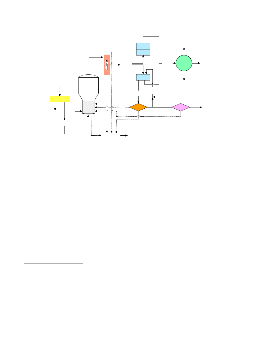
BIOSYN Gasification and Gas Conditioning Technologies: The BIOSYN gasification process
1
(Figure 1) was developed during the 1980s by BIOSYN Inc., a subsidiary of Nouveler Inc., a
division of Hydro-Quebec (Montréal, Quebec, Canada). The process is based on a bubbling
fluidized bed gasifier containing a bed of silica or alumina capable of operating up to 1.6 MPa.
Extensive oxygen-blown biomass gasification tests were conducted during 1984 to 1988, in a 10 t/h
demonstration plant located at St-Juste de Bretennieres, Québec, Canada, to produce synthesis gas
for methanol production. Air blown atmospheric gasification tests were also conducted for
evaluating cogeneration. In the following years, a 50kg/h BIOSYN process development unit has
also proven the feasibility of gasifying primary sludges, RDF, rubber residues (containing 5 - 15%
Kevlar), and granulated polyethylene and propylene residues to produce hydrogen-rich synthesis
gases.
The process accepts feed particle sizes up to 5 cm, feed bulk densities higher than 0.2 kg/l and feed
moisture content up to 20%. The thermal efficiency for biomass gasification varies from 70 to 80%.
The product gas containing mostly CO, CO
2
, and H
2
could be cleaned to remove carry over dust
and condensable tar and upgraded to produce high-purity hydrogen. With air as the gasifying agent
the HHV of the fuel gas is about 6 MJ/Nm
3
. Enriched air, with 40% oxygen, can produce a fuel gas
having a higher heating value (HHV) of about 12 MJ/Nm
3
at half the gas yield. The raw gas
cyclones remove 85 to 95% of entrained particles.
Page 2
Bubbling
Fluid-Bed
Atmospheric or
Pressurized
Gasifier
O
2
enriching unit
Air
Biomass:
• Forest residues
• Agri-residues
MSW (RDF)
Non recyclable plastics
Sludges
N
2
-rich
stream
O
2
-rich
stream
Solid Residues
from process
Synthetic
Gas
Catalytic
Tar Reforming
Hot Gas
Filtration
Three-stage
Scrubbing
Option 1
Option 2
Skimming
Aqueous
Phase
Recycling
(in construction materials)
Water
Purge
Phase
Energy
Production
Clean
Synthetic
Gas
kWt
kWe
Flue
Gases
Discharge
Water
tar
Feedstock
•
The BIOSYN Options for Waste & Biomass
Gasification & Synthetic Gas Conditioning
Aqueous
Treatment
Treated
•
•
Recycle Treated Water
•
Recycle
Aqueous
Phase
Figure 1: BIOSYN Process
The supporting R& D conducted during the demonstration of the BIOSYN Process, includes gas
scrubbing for efficient tar removal with reduced water requirements, recycling the insoluble tars to
the gasifier, wet oxidation and adsorption of dissolved organic compounds in the scrubbing water,
and recycling carbon-rich ashes and carry over carbon with adsorbed organic compounds to the
gasifier. The R& D effort also included hot-gas filtration of entrained dust using a static bed of
perlite particles and a moving sand bed filter, and catalytic steam cracking of tar. Proprietary gas
clean-up catalysts were developed to decompose 99% of tars and 97% of naphthalene compounds.
The fully integrated BIOSYN Process, with hot-gas filtration and high-temperature tar reforming,
water-gas shift conversion to convert CO to hydrogen and CO
2
, and CO
2
removal to produce high-
purity hydrogen, was never demonstrated. The BIOSYN Process is now commercialized by
Enerkem Technologies Inc, a subsidiary of the Kemestrie Group, a spin-off company of the
University of Sherbrooke. Recently, a commercial installation to gasify 2.2 t/h of granulated
polypropylene residues was planned for construction in Spain. Environmental International
Engineering S.L., a Spanish-based development and engineering group, in partnership with
Enerkem, was planning to erect and commission the plant. The electricity output of the plant will be
sold to the grid.
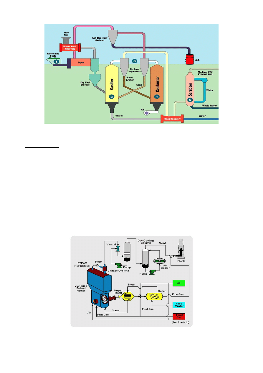
FERCO SilvaGas Process : The FERCO SilvaGas Process
2
(Figure 2) employs the low-pressure
Battelle (Columbus) gasification process which consists of two physically separate reactors; a
gasification reactor in which the biomass is converted into a medium calorific value (MCV) gas and
residual char at a temperature of 850º to 1000ºC, and a combustor that burns the residual char to
provide heat for gasification. Heat transfer between reactors is accomplished by circulating sand
between the gasifier and combustor. Since the gasification reactions are supported by indirect
heating, the primary product is a synthesis gas with medium calorific value. A typical product gas
composition obtained in pilot plant tests, at steam to biomass (wood chips) ratio of 0.45, is 21.22%
H
2
, 43.17% CO, 13.46% CO
2
, 15.83% CH
4
, and 5.47% C2+. The estimated HHV of this fuel gas is
17.75 MJ/N m
3
. A 200 t/d capacity Battelle demonstration gasification plant was built at the McNeil
Power plant in Burlington, Vermont. Following plant shakedown and initial tests the plant has
operated intermittently. At this plant, the fuel gas was co-fired in the existing McNeil wood fired
boiler. The process was developed by US DOE Biomass Power Program, FERCO, Battelle
Columbus Laboratory, Burlington Electric Department, Zurn Industries, OEC/Zurn, and NREL.
Page 3
Figure 2: SilvaGas Process
MTCI Process: The MTCI gasification process (Figure 3) also employs indirect heating to promote
steam gasification of biomass to produce a MCV fuel gas. The gasifier combusts part of the fuel gas
in pulsed combustion burners which promote heat transfer to the gasification section. Extensive
pilot plant tests were conducted in a 20 t/d process development unit (PDU) at the MTCI
laboratories near Baltimore, Maryland. These tests also included evaluation of black liquor
gasification process. Based on the PDU tests a 50 t/d capacity black liquor gasification
demonstration unit was built at Weyerhauser’s New Bern facility.
In the MTCI Process, the black liquor is steam reformed/gasified at an operating temperature of
about 600ºC (~1,110ºF). The raw gas is upgraded through several steps of gas cleanup, resulting in
a synthesis gas rich in hydrogen (>65% by volume) with a higher heating value (HHV) of
approximately 10.4 MJ/(dry)Nm
3
. In one of the pilot test campaigns, cleaned synthesis gas was
metered to a solid-oxide fuel cell (SOFC,) operating at about 1000ºC (1,830ºF), which produced a
net 2.6 volts D.C., 62 amps or an equivalent of 161 watts of electricity.
Figure 3: MTCI Process
Page 4
The first MTCI black liquor gasification plant was commissioned in September 2003, at the
Norampac mill in Trenton, Ontario, Canada. The plant was designed to handle 115 TPD back liquor
(60% solids). The gasifier has operated for extended periods, but has experienced some bed
agglomeration problems. The second MTCI plant, with a capacity of 200 TPD sodium carbonate
black liquor (with 60% solids), was launched in 2001 by Georgia Pacific (GP), Fluor Daniels, and
Stone Chem, with support from USDOE. The five-year demonstration project is located at the GP
paper mill in Big Island, Virginia. The project will cost approximately $87 MM with about 50%
cost contribution from industry. Plant commissioning was started in the fall of 2004, and to date the
unit has operated at 50% of design capacity. No agglomeration problems were observed at this
demonstration plant.
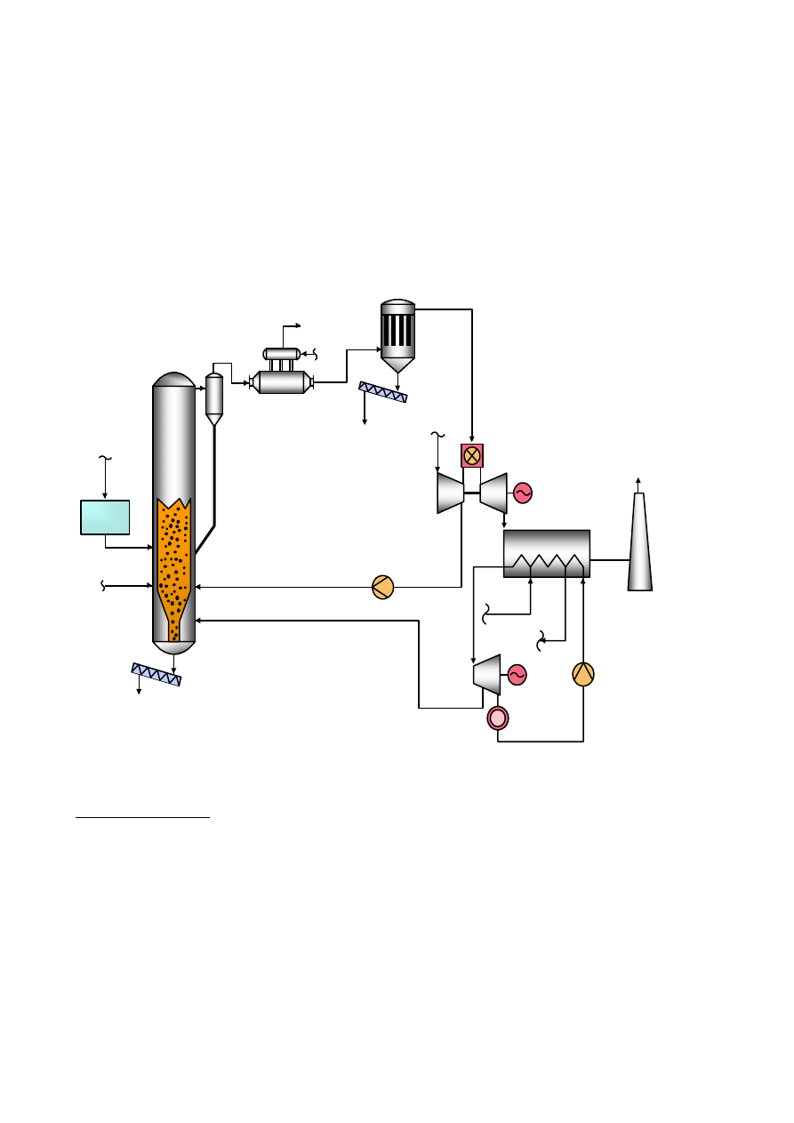
Figure 4: RENUGAS Process
RENUGAS Process: The GTI/IGT RENUGAS
Process
4
(Figure 4) employs a 20 bar pressurized
bubbling fluidized bed process. The process was extensively tested with a variety of biomass
materials, including bark-paper sludge mixtures, bagasse, and pelletized alfalfa stems in a 12 TPD
PDU at IGT test facilities in Chicago. Subsequently USDOE selected the RENUGAS Process for
scale-up and demonstration, using bagasse, at the HC&S sugar mill at Paia in Hawaii. The project
was terminated when the 100 TPD demonstration plant had limited success in handling the low-
density, shredded bagasse.. A typical gas composition obtained in the IGT PDU with bagasse at
2.24 MPa, and 850ºC is 19%H
2
, 26% CO, 37%CO
2
, 17% CH
4
, and 1% C2+. The heating value of
this fuel gas is approximately 13 MJ/Nm
3
. The project participants included US DOE Biomass
Power Program, IGT, Westinghouse Electric Corporation, State of Hawaii, PICHTR, and HC&S.
Although, the pressurized air-blown RENUGAS process was initially developed for IGCC
applications, by replacing air with oxygen, the process could produce synthesis gas that could be
upgraded to high-purity hydrogen.
FUEL
HANDLING
SORBENT/
BED MATERIAL
FUEL
GASIFIER
CYCLONE
GAS
COOLER
STEAM TO
HRSG
FROM
HRSG
FLY ASH
PARTICULATE
REMOVAL
CLEAN PRODUCT GAS
GAS
TURBINE
HEAT RECOVERY
STEAM GENERATOR
STACK
STEAM
TURBINE
DISTRICT HEAT
OR CONDENSER
BOOSTER
COMPRESSOR
AIR
STEAM
ASH AND
SPENT
SORBENT
AI
R
TO GAS
COOLER
FROM GAS
COOLER
Page 5
Carbona which licensed the Renugas technology from GTI has constructed and tested a 15 MWth
high-pressure (20 bar) Renugas pilot plant in Tampere, Finland.
5
Around 1993, Carbona has
successfully operated the pressurized gasifier for over 2000 hours with a variety of biomass wastes
and has also evaluated hot-gas filtration for IGCC application. In October 2004, Carbona reported
that ground has been broken for building a 5.4 MWe capacity low pressure, Renugas demonstration
project in Skive, Denmark. The project will start its operations with palletized wood.
In January 2005, GTI completed the shakedown of a new 24 t/d, adiabatic Flex Fuel Test Facility in
Des Plaines, Illinois.
5
This facility is capable of gasifying up to 30 TPD of biomass and at operating
pressures up to 25 bar.
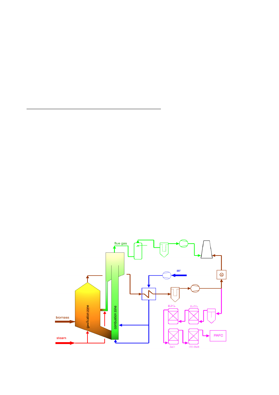
Forced Internal Circulation Fluidized Bed (FICFB) Process: The two-stage, combined fluidized bed
gasifier and CFB combustion process developed by the Technical University of Vienna (TUV),
Austria (Figure 5) with Repotec has demonstrated exceptional rapidity of success in scaling-up the
laboratory scale unit to a commercial demonstration plant Güssing, Burgenland.
6
The characteristic
features, progress and performance of the TUV in Güssing, demonstration for CHP are widely
published. The principal novelty of the process is its ability to produce a MCV fuel gas without the
use of oxygen. The process employs a catalytically active circulating fluidized bed of solids that can
reduce tar in the raw gases. The raw product gases are cooled for heat recovery and scrubbed with
an organic liquid to remove most of the tar. The raw MCV product gas can be processed to produce
hydrogen or hydrogen-rich gas. The condensate along with some of the scrubber solvent is recycled
to the combustion zone for complete thermal decomposition of all condensable organic compounds
produced during BMG. The clean gas is then introduced to an Jenbacher gas engine to generate a
gross ~2.0 MWe power and ~4.5 MWth heat. The reported parasitic power consumption is ~0.2
MWe. The electrical efficiency of the Jenbacher gas engine is 36 to 37%. At the end of 2004, the
gasifier has logged in more than 14,000 hours and the total operating time with the integrated
gasifier and gas engine is about 11,000 hours.
A typical dry, raw gas composition reported from air-blown biomass gasification tests is given
below in % by volume: H
2
= 30-45, CO= 20-30, CO
2=
15-25, CH
4
= 8-12 vol.%, N
2
=1-5, (NH
3
=
500-1000 ppm, H
2
S= 20-50 ppm, Tar= 0.5-1.5 g/Nm³, Particles= 10-20 g/Nm³).
Figure 5: FICFB Gasification Process
Page 6
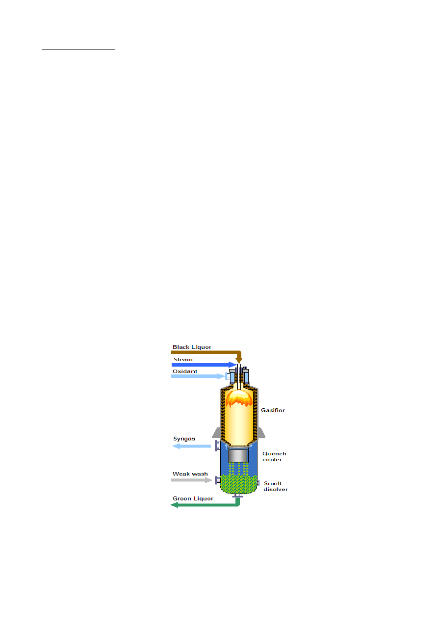
CHEMREC Process: In 1987, the development of the Chemrec Process
7,8
(Figure 6) for black
liquor gasification was started in Sweden. The process was bought by Kvaerner in 1990. In 2000
Kvaerner sold their majority rights to the German industrial group Babcock Borsig Power (52%)
and to the Swedish company Nykomb Synergetics (24%). Since 2002, Chemrec has been in search
of seeking new industrial partners because Babcock Borsig Power is in insolvency and its part in
Chemrec has been bought by Nykomb Synergetics.
The Chemrec process can be operated at slightly above atmospheric pressure for incremental black
liquor gasification in parallel with an existing recovery boiler. The process when operated under
pressurized system can replace the recovery boiler. The pressurized gasification combined cycle
mode (BLGCC) is more energy efficient than the recovery boiler and can generate approximately
double the amount of electric power than a modern recovery boiler. The Chemrec gasification
reactor is similar to the Texaco gasifier (now owned by GE). Black liquor is injected with oxygen,
into a high-pressure (~ 30 bar) and high temperature (~950ºC) reactor to gasify the cellulose, lignin
components and smelt and reduce the inorganic salts. The favorable reaction kinetics in the gasifier
due to the presence of a catalyst (Na and K) results in low methane content gas compared to normal
gasification of biomass. In the low-pressure Chemrec process, black liquor is gasified with air.
Atomization and droplet size are very important to gasifier performance; atomization is achieved
using medium pressure steam. The high-pressure Chemrec process is operated with oxygen. The
black liquor injection nozzles are designed to facilitate on-line cleaning. The reactor temperature is
maintained at about 950ºC in the lower part of the gasifier. An oil or gas fired burner at the top of
gasifier is used to heat the gasifier for start-up and for hot stand-by. The chemical smelt is
recovered from the gas stream at the base of the gasifier by quenching with condensate. The product
green liquor is pumped to the mill system. A small quantity (a few percent) of sulfur, as H
2
S, leaves
with the product gas in the low-pressure system while approx 60% of sulfur leaves with the product
gas in the high-pressure system. In the pressurized system, the H
2
S is removed by scrubbing
employing standard H
2
S / COS removal technology. By proper selection of the desulfurization
scrubbing process, the absorption of CO
2
can be reduced. With air gasification, the product is an
LCV gas, while pressurized oxygen blown gasification results in a MCV gas
Figure 6: The Chemrec Process
Chemrec has provided the following data on gasifier performance, for the low and high pressure (30
bar) gasification cases. The gas compositions are from two slightly different black liquor feed
stocks.

Page 7
Table 2-2: Gasifier Performance Predictions for Operation with Air and Oxygen
Low Pressure
High Pressure
Air Blown
Oxygen-blown
Assumptions:
Reactor
Temp,
°C
950
950
Reactor
Pressure,
bar
2 30
Air feed, t/tds
2.2
O2
feed,
t/tds
---
0.34
Oxidant temp, °C
100
135
Gas Composition (vol. %):
CH
4
0.2
1.1
CO
6.0
29.5
CO
2
12.5
14.6
COS
-
0.04
H
2
8.6
31.1
H
2
O
26.3
22.2
H
2
S
0.2
1.5
NH3
0.01
0.00
N2
+
Ar 46.2
0.18
Higher heating value
(MJ/m3, dry, at 15
o
C)
2.6
10
Typical black liquor properties are: C 37.2%, H 3.6%, O 34.4%, S 3.7%, N 0, Na 18.6%, K 2.5%,
HHV: 14.36 MJ/kg, dry
The Swedish Government is providing $25 MM (50% matching founds) to develop and verify the
performance of the Chemrec pressurized process in two steps. Chemrec has constructed a 20 t/d dry
solids (3 MWth), oxygen-blown development plant in Piteå, Sweden. After about one year of
testing the process will be scaled up to a 300 t/d dry solids capacity and built as a complete BLGCC
plant. The Kappa Kraftliner mill in Piteå has expressed a desire to provide the host site for the plant.
This effort, which began in 2001, will continue through 2006. Upon successful operation in the 20
t/d development plant, US pulp & paper industry and US DOE may consider building a commercial
BLGCC demonstration based on the Chemrec technology in USA
As shown, the gas composition from the pressurized Chemrec process is well suited for further
treatment to produce synthesis gas which then can be converted into automotive fuels such as
methanol, DME, FTD or hydrogen.
The operation of a 300 TPD dry solids capacity, low-pressure Chemrec gasifier in New Bern
(Weyerhaeuser Mill) was started in 1996 and stopped in January 2000 when a crack was detected in
the reactor vessel. The plant was taken out of operation and extensive investigations were carried
out to understand and come up with a new design to avoid further structural problems. The plant
construction was modified and the Weyerhaeuser gasifier has resumed operation in 2003. The new
gasifier refractory is expected to last for about two years while the previous lining operated
satisfactorily for a little over one year.
SVZ Schwarze Pumpe GmbH: SVZ
9
has converted some of the existing former East German era,
FDV Process coal gasifiers in Schwarze Pumpe, Germany to convert biomass, coals, and wastes
into clean fuel gas and synthesis gas (Figures 7a, 7b, 7c). The plant gasifies a wide variety of waste
materials along with low-rank coals in an updraft moving bed gasifier. The waste materials include
demolition wood, used plastics, sewage sludge, auto-fluff, MSW, contaminated waste oil, paint and
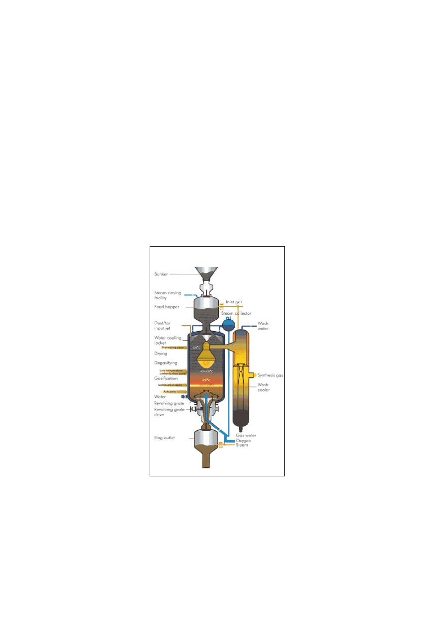
Page 8
varnish sludge, mixed solvents, tars, and on-site process waste streams. The waste materials are
blended with coal at a ratio of 4:1. SVZ has developed an effective feed handling system which
employs thermal pretreatment to convert heterogeneous feed materials to produce a nearly uniform
in shape and bulk density gasifier feedstock.
The oxygen-blown, 25 bar-pressurized, 14 t/h FDV process, similar to Lurgi’s moving bed coal
gasification process, converts the mixed feedstocks to MCV fuel gas or synthesis gas. The raw gas
is subjected to conventional (Rectisol) gas cleaning to separate contaminants from the product gas.
The SVZ facility has also built a 25 bar pressurized, 35 t/h capacity British Gas Slagging Lurgi
gasification system for converting mixed feed stocks to MCV fuel gas or synthesis gas. As is the
case with the FDV Process, the raw gas is subjected to conventional gas cleaning to produce a clean
product gas and liquid and solids containing waste slurry stream.
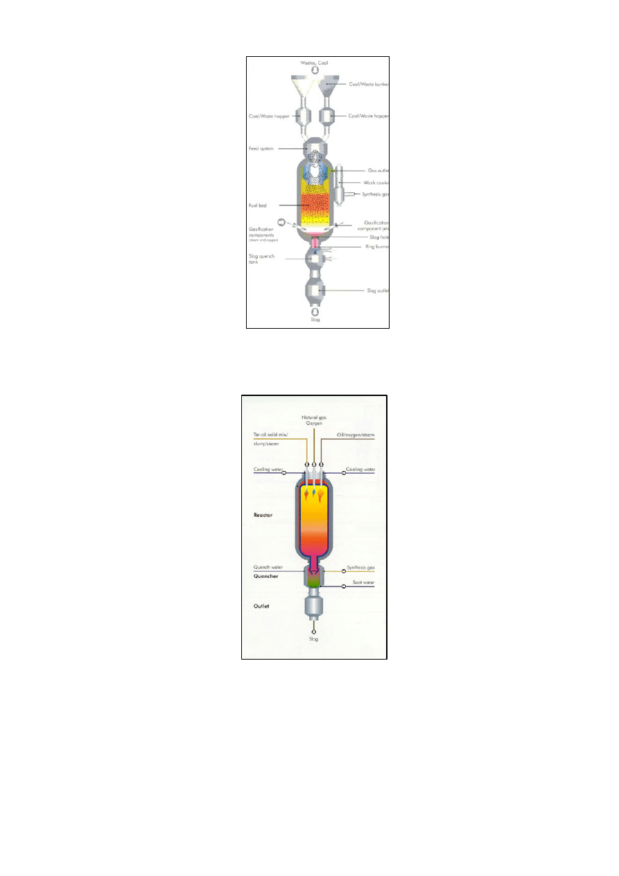
The third oxygen-blown, refractory lined gasifier is the FSV 15 t/h entrained flow gasifier, similar
to the TEXACO process, which serves the role of a “bottoming” gasifier that effectively treats the
hydrocarbons containing waste streams from gas processing into a contaminant-free synthesis gas
and mineral slag. If required, a supplementary fuel, i.e. natural gas is used to maintain the reactor
temperature in the range of 1600ºto 1800ºC. This process is today owned by Lurgi and called the
Multi Purpose Gasifier.
Figure 7A: Pressurized Moving Bed Gasifier with Revolving Grate
Page 9
Figure 7B: Pressurized Moving Bed Gasifier with Liquid Slag Discharge
Figure 7C: SVZ Schwarze Pumpe Entrained Flow Gasifier with Slag Discharge
The SVZ plant is a first-of-a-kind integrated gasification, methanol and combined-cycle electricity
production plant that converts contaminated and difficult to handle waste materials to clean, value-
added products. The high gasification temperatures of up to 1,800°C are high enough to totally
decompose contaminants in the product gas or gas scrubbing effluent streams. The vitrified slag, the
only gasifier waste product, safely encapsulates any residual pollutants and can be used as
construction material.

Page 10
In July 2002, SVZ was sold to ORESTO, a subsidiary of Nord GB Gesellschaft für Beteiligungen
mbH, Hamburg.
CHRISGAS Project: Between 1993 and 1999, Sydkraft Ab adopted the Ahlstrom/FW CFB
gasification process to develop and demonstrate the first pressurized Bioflow biomass gasification
IGCC process for CHP (9 MWth and 6 MWe) application in Värnamo, Sweden.
7
This
demonstration, widely recognized for its technical success, operated the pressurized CFB gasifier
for about 8500 hours. The integrated operation of the pressurized gasifier with hot-gas clean-up and
power generation in a close-coupled Alstom’s (now part of Siemens) Typhoon gas turbine was
demonstrated for over 3600 hours. Although, the facility has been mothballed for several years, it
will be reactivated as the center piece for demonstrating the CHRISGAS project, a multi-national
consortia technology development effort. The project’s mission is to develop pressurized, oxygen-
blown gasification of biomass and wastes to produce synthesis gas and its subsequent conversion to
transportation liquid fuels.
9
The results from the CHRISGAS project should be also useful for
evaluating the production of hydrogen from biomass.
The CHRIS GAS project is coordinated by Växjö University at the Växjö Värnamo Biomass
Gasification Centre (VVBGC). The Project team includes, AGA-Linde, Catator, KS Ducente, Royal
Institute of Technology (KTH), S.E.P. Scandinavian Energy Project, TPS Termiska Processer,
(Valutec),Växjö Energi, TK Energi, DK, Valutec, FI, FZ Jülich, DE, Linde, Pall Schumacher,
University of Bologna, IT, Technical University Delft, NL, and CIEMAT, ES. The project budget is
more than €18 MM.
RESEARCH NEEDS
The following sections highlight research needs for developing and commercializing biomass
gasifiers for hydrogen production.
Feed Preparation: Unlike fossil fuels, biomass is dispersed and lacks the infrastructure to ensure
sustained supply of low-cost quality controlled gasification feedstock. Biomass has certain physical
characteristics, such as low bulk density and its fibrous nature that presents many challenges in
collection and transportation to a central gasification plant. Although, the feed preparation and feed
handling systems for woody biomass are well developed for low-pressure systems, reliable feeders
for other types of biomass for pressurized gasifiers require further development. Low-cost
pelletization of low-density herbaceous feedstocks would widen the range of renewable feed
materials that are available for biomass gasification. Pellets are easy and economical to transport
and their relatively uniform shape and bulk density would render them easy to handle, store and
feed pressurized systems.
Biomass Gasification: The present gasification systems are generally designed and operated to
produce fuel gas for heat and power. The processes described above also produce a fuel gas with
little or no inert N2, i.e., produce a synthesis gas containing primarily CO, H
2
, CO
2
, H
2
O(g), and
some gaseous hydrocarbons and condensable hydrocarbons. Fundamental research is needed to
improve product selectivity, to produce essentially high-purity H
2
. The role of catalytic and non-
catalytic bed additives on raw product gas yield and thermodynamic limitations should be
investigated. Nearly total carbon conversion to produce high-purity H
2
would require minimal gas
cleaning and separation to produce pure H
2
. It is conceivable that direct-H
2
yield could be improved
by varying certain aspects of gasification reactor designs and operating conditions. Gasification
reactors should also be designed to incorporate the capability to thermally decompose organic
condensates and ammonia that would be produced from systems employing conventional low-
temperature gas cleaning and quenching.

Page 11
Robust and sturdy low-cost, high-temperature heat transfer materials, which can operate up to
1100ºC (~2000ºF) would help develop indirectly heated reactor designs that would prevent products
of combustion from contaminating steam- or ‘recycled product gas.’
Small-scale, low-cost air enrichment is another technology that will be beneficial to produce
hydrogen production from biomass.
Raw Gas Handling and Clean-up: Significant progress has been made over the past 10 years
towards developing a better understanding of biomass gas handling and conditioning processes and
technologies for use in biomass gasification for advanced power production. However, there is need
for further R&D in this process step for removal or elimination of particulates (from attrition of
gasifier solids and secondary vapor-phase carbonaceous materials), alkali compounds, tar,
chlorides, and ammonia. High-temperature gas processing, including reforming of hydrocarbons
and water-gas shift to convert CO to H
2
should be investigated, particularly for raw product gases
with all its contaminants produced in biomass gasification. In order to improve the overall thermal
efficiency and to retain process simplicity, it is desirable to conduct these gas cleaning at raw gas
temperatures or at temperatures which may require some gas cooling but does not require any
reheating of raw cleaning gases. Gas cooling and design of appropriate heat exchangers have
become the focus of the recent demonstration at the Essent/AMER and ARBRE biomass
gasification projects, for co-firing and power generation applications. In the development of high-
efficiency gasification systems, it may be necessary that most if not all of these gas handling and
gas clean-up R&D should be conducted at elevated pressures that match with the end-use for
product H
2
.
Gas cleaning R&D should also investigate CO
2
removal at high temperatures, although it may not
be required for biomass gasifiers that may be developed for molten carbonate fuel cells. Physical
and ionic separation membranes that can separate H
2
at high temperatures would be useful to
produce high-purity H
2
, while CO or gaseous hydrocarbons are being chemically converted to H
2
.
Gas cleaning in general will have a major impact on the environmental impact of biomass gasifiers.
Incomplete gas cleaning would shift the contaminant removal problem to some other location
downstream from the gasifier, requiring expensive treatment of all process effluents.
Interface Issues and System Integration: As is the case with other energy conversion schemes, there
could be several unique issues that need to be addressed for integrating hydrogen producing
biomass gasification systems with selected end use applications. Obviously a central hydrogen
producing biomass gasifier or gasifiers feeding to a central hydrogen storage and distribution
system may face simpler problems compared to hydrogen producing biomass gasifiers that are
closely coupled to selected chemical or energy conversion systems. Examples of the latter include
issues related to coupling gasifiers with high-temperature fuel cells.
System Definition and Market Assessment: Whenever, ‘biomass gasification to hydrogen’ becomes
commercial, it would be necessary to determine the range of capacity of conceptual commercial
plants. These specifications would be dependent to a great extent on the application, the cost and
availability of feedstock. Upon defining the basic plant specifications, it would be possible to
determine the process economics, their advantage over conventional alternatives, and hence the
market potential for biomass gasifiers for specific applications.
Information Dissemination and Policy: To promote the successful development and
commercialization of biomass gasifiers for hydrogen production and utilization, timely
dissemination of information is absolutely essential. Given the competition from conventional
sources of hydrogen, public education and information are definitely required to craft, deploy, and
implement policies that are conducive to commercializing hydrogen producing biomass gasification

Page 12
systems. It is crucial to document the performance of the new biomass gasification systems, to
highlight success stories but also in showing solutions to problems that may arise. The deployment
of hydrogen producing biomass gasification systems for high-efficiency and selected value-added
applications will benefit from policies that encourage the use of renewable fuels.
REFERENCES
1. International Energy Association (1997), “State of the Art of Biomass Gasification, Prepared
by European Concerted Action, Analysis and Coordination of the Activities Concerning
Gasification of Biomass”, AIR3-CT94-2284 and IEA Bioenergy, Biomass Utilization, Task
XIII, Thermal Gasification of Biomass Activity, Canadian Country Report
2.
Paisley, M.A., and Overend, R.P., (2002), “The SylvaGas Process from Future Energy
Resources – A Commercialization Success”, 12th European Biomass Conference, June 17-21,
2002, Amsterdam, The Netherlands; (www.fercoenterprises.com/
downloads/Amsterdam%20020619.pdf]
3. Momtaz N. Mansour, Ravi R. Chandran and Lee Rockvam, The Evolution of and Advances in
Steam Reforming of Black Liquor, Manufacturing and Technology Conversion International,
Inc., (
www.tri-inc.net/EvolutionSR.pdf)
4. Spliethoff, H. (2001), “Status of Biomass Gasification for Power Production”, IFRF
Combustion Journal, Article No. 200109
5. Contact: Suresh P. Babu, Gas Technology Institute, 1700 South Mount Prospect Road, Des
Plaines, IL 60018, USA, E-mail:
suresh.babu@gastechnology.org
6. Rauch, et.al, (2004), “Steam Gasification of Biomass at CHP Plant in Guessing - Status of the
Demonstration Plant,” Second World Conference and Technology Exhibition, Biomass for
Energy, Industry and Climate Protection, May 10-14, Rome, Italy.
[www.gastechnology.org/iea]
7. International Energy Association (1997), “State of the Art of Biomass Gasification, Prepared
by European Concerted Action, Analysis and Coordination of the Activities Concerning
Gasification of Biomass”, AIR3-CT94-2284 and IEA Bioenergy, Biomass Utilization, Task
XIII, Thermal Gasification of Biomass Activity, Sweden Country Report
8. Consonni, S., Larson, E.D., Kreutz, T.G., and Berglin, N., 1998, "Black Liquor-Gasifier/Gas
Turbine Cogeneration," ASME J. Engng. for Gas Turbines & Power, Vol. 120, pp.442-449.
9. CHRISGAS(2004), [www.chrisgas.com]
END
Wyszukiwarka
Podobne podstrony:
więcej podobnych podstron