Moeller GmbH
Industrieautomation
Hein-Moeller-Straße 7–11
D-53115 Bonn
E-Mail: info@moeller.net
Internet: www.moeller.net
© 2002 by Moeller GmbH
Subject to alteration
AWB-C27-1293-GB xx/xx/XBS 12/04
Printed in the Federal Republic of Germany (0x/02)
Article No.: xxxxxx
4 *patpks#nycmyn*
Rück
e
nte
x
t
A
A
Think future. Switch to green.
Think future. Switch to green.
Building Automation
Systems
Industrial Automation
Hardware and Engineering
12/0
3 AWB-C27-1293-GB
MI4
Display and Operator Panel
A
Rückenbreite bis 10 mm (1 Blatt = 0,106 mm für XBS)

All brand and product names are trademarks or registered
trademarks of the owner concerned.
1
st
published 1997, edition date 09/97
2
nd
edition 09/99
3
rd
edition 05/01
4
th
edition 03/03
5
th
edition 12/0
3
See revision protocol in the “About this manual“ chapter
© Moeller GmbH, 53105 Bonn
Author:
Norbert Mausolf
Editor:
Thomas Kracht
Translator:
Dominik Kreuzer
All rights reserved, including those of the translation.
No part of this manual may be reproduced in any form
(printed, photocopy, microfilm or any other process) or
processed, duplicated or distributed by means of electronic
systems without written permission of Moeller GmbH, Bonn.
Subject to alteration without notice.
Rückenbreite festlegen! (1 Blatt = 0,106 mm)

I
Before commencing the installation
• Disconnect the power supply of the device.
• Ensure that devices cannot be accidentally
restarted.
• Verify isolation from the supply.
• Earth and short circuit.
• Cover or enclose neighbouring units that
are live.
• Follow the engineering instructions (AWA)
of the device concerned.
• Only suitably qualified personnel in
accordance with EN 50110-1/-2
(VDE 0105 Part 100) may work on this
device/system.
• Before installation and before touching
the device ensure that you are free of
electrostatic charge.
• The functional earth (FE) must be
connected to the protective earth (PE) or
to the potential equalisation. The system
installer is responsible for implementing
this connection.
• Connecting cables and signal lines should
be installed so that inductive or capacitive
interference does not impair the
automation functions.
• Install automation devices and related
operating elements in such a way that they
are well protected against unintentional
operation.
• Suitable safety hardware and software
measures should be implemented for the
I/O interface so that a line or wire breakage
on the signal side does not result in
undefined states in the automation
devices.
• Ensure a reliable electrical isolation of the
low voltage for the 24 volt supply. Only
use power supply units complying with
IEC 60364-4-41 (VDE 0100 Part 410) or
HD 384.4.41 S2.
• Deviations of the mains voltage from the
rated value must not exceed the tolerance
limits given in the specifications, otherwise
this may cause malfunction and dangerous
operation.
• Emergency stop devices complying with
IEC/EN 60204-1 must be effective in all
operating modes of the automation
devices. Unlatching the emergency-stop
devices must not cause restart.
• Devices that are designed for mounting in
housings or control cabinets must only be
operated and controlled after they have
been installed with the housing closed.
Desktop or portable units must only be
operated and controlled in enclosed
housings.
Mo
eller
Gmb
H
Safety in
struc
tion
s
Warning!
Dangerous electrical voltage!

II
• Measures should be taken to ensure the
proper restart of programs interrupted
after a voltage dip or failure. This should
not cause dangerous operating states even
for a short time. If necessary, emergency-
stop devices should be implemented.
• Wherever faults in the automation system
may cause damage to persons or property,
external measures must be implemented to
ensure a safe operating state in the event
of a fault or malfunction (for example, by
means of separate limit switches,
mechanical interlocks etc.).

1
12
/0
3
AWB
-C
2
7-
12
93
GB
Display Units And Operator Panels
Connecting a PC or printer to the MI4
Data interfaces of MI4-140-KF1 (hand-held)
Connect MI4 (hand-held) to PLC
Connecting the MI4 (hand-held) to
PC or printer (through CN2)

3
12
/0
3
AWB
-C
2
7-
12
93
GB
About This Manual
List of Modifications
The following major changes have been made since
edition 09/99:
MI4 documentation
This manual describes MI4 series display units and
operator panels.
Additional manuals for the MI4 include the following:
Training Guide (AWB27-1302GB)
User Interface for MI4-CFG-1-GB Configuration
Software (AWB-C27-1294GB)
MI4-PLC Communication:
Application module and function blocks
(AWB-C27-1303GB)
Symbols used
The following symbols are used in this manual:
왘 Indicates action to be taken.
Edition Date
Page
Keywords
New
Modification
Omitted
05/01
Complete
manual
New devices,
additional data interfaces
(Siemens MPI, DeviceNet, CANopen)
03/03
MI4-140-TA1, MI4-170/570-KH1,
12/03
MI4-110-KD1, MI4-130-TA1
)
Provides useful tips and additional information.

4
12
/0
3
AWB
-C
2
7-
12
93
GB

5
12
/0
3
AWB
-C
2
7-
12
93
GB
1
Display Units And Operator Panels
Panel overview
The display units and operator panels are divided
into three groups:
Text operator panels
These are distinguished by
the type of display (text-based/graphics-
capable),
the size of the display,
the number of interfaces,
the number of keys.
In addition, a hand-held unit and a device with
prepunched holes for electromechanical control
circuit devices are available.
Graphic operator panels with LCD display
These are distinguished by
the size and type of display
(colour or monochrome),
the number of keys.
Touch panels
These are distinguished by
the size and type of display
(colour or monochrome),
the number of additional buttons.
Depending on the device type, inputs are made
either using a keypad or a touch screen. In the latter
case, only slight pressure on the display triggers a
function (resistive touch technology).
All graphic/text/touch operator panels are equipped
with interfaces for configuration with a PLC or a PC.
Most of the units have a serial printer port.
Display Units And Operator
Panels
6
12
/0
3
AWB
-C
2
7-
12
93
GB
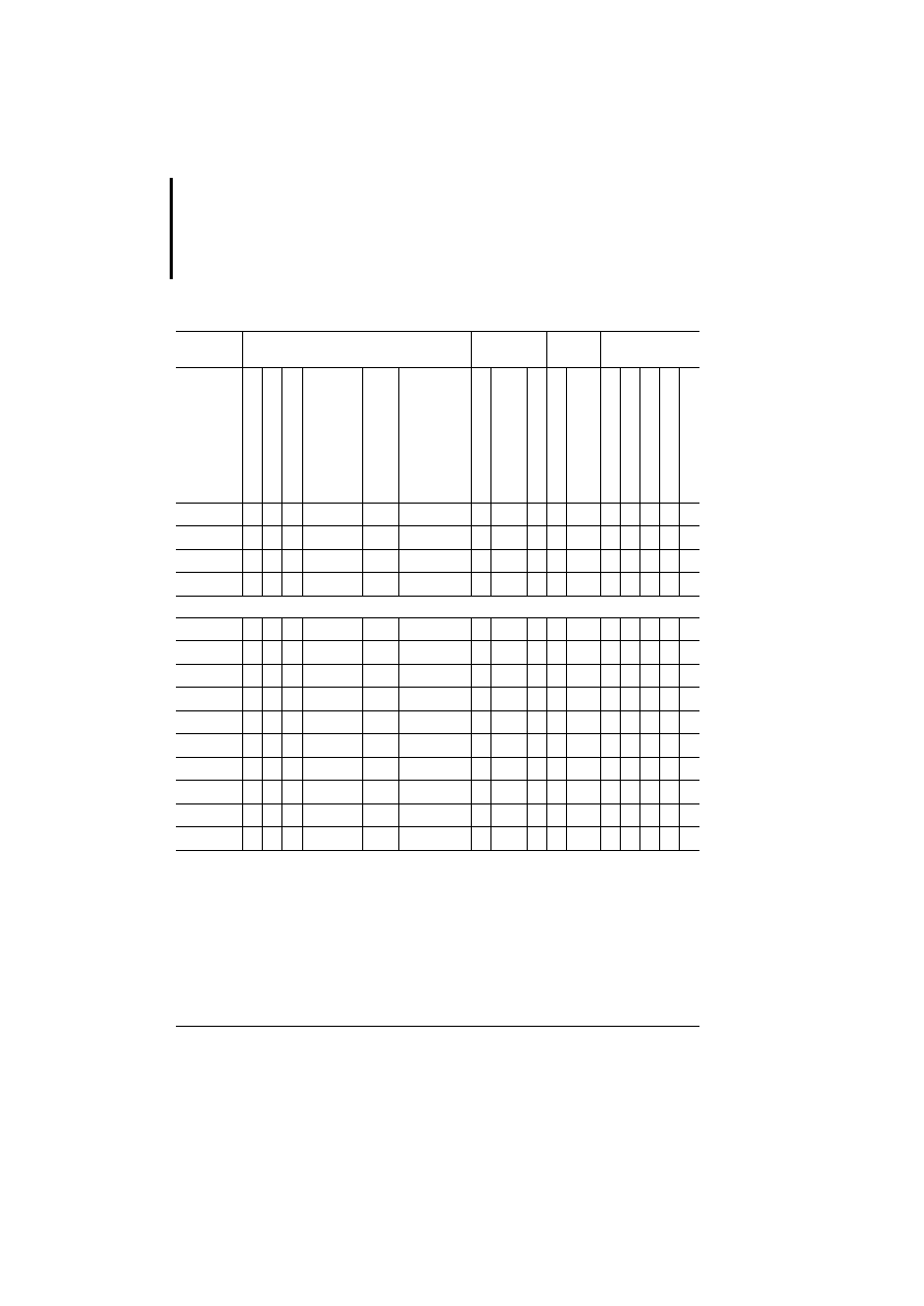
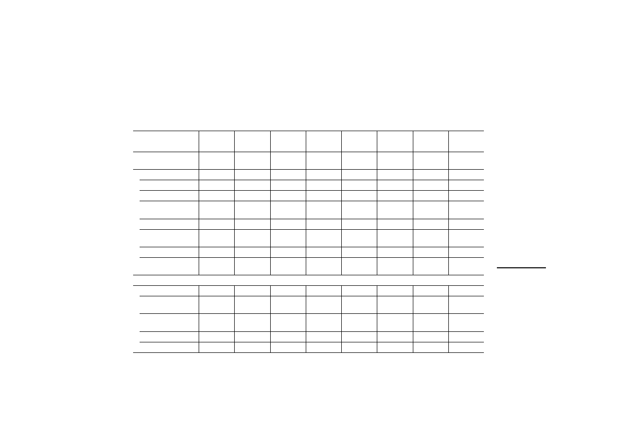
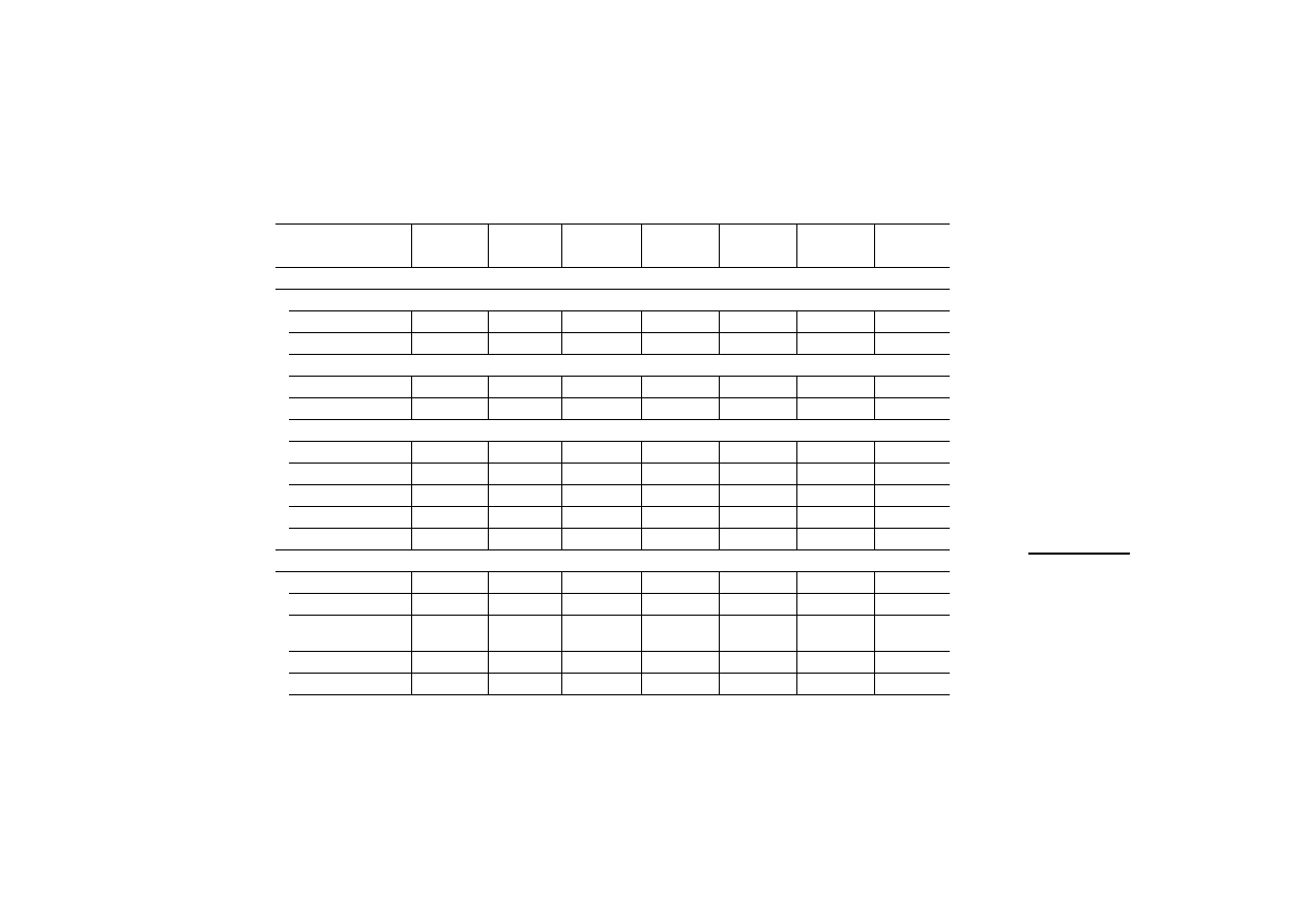
Features
Overview
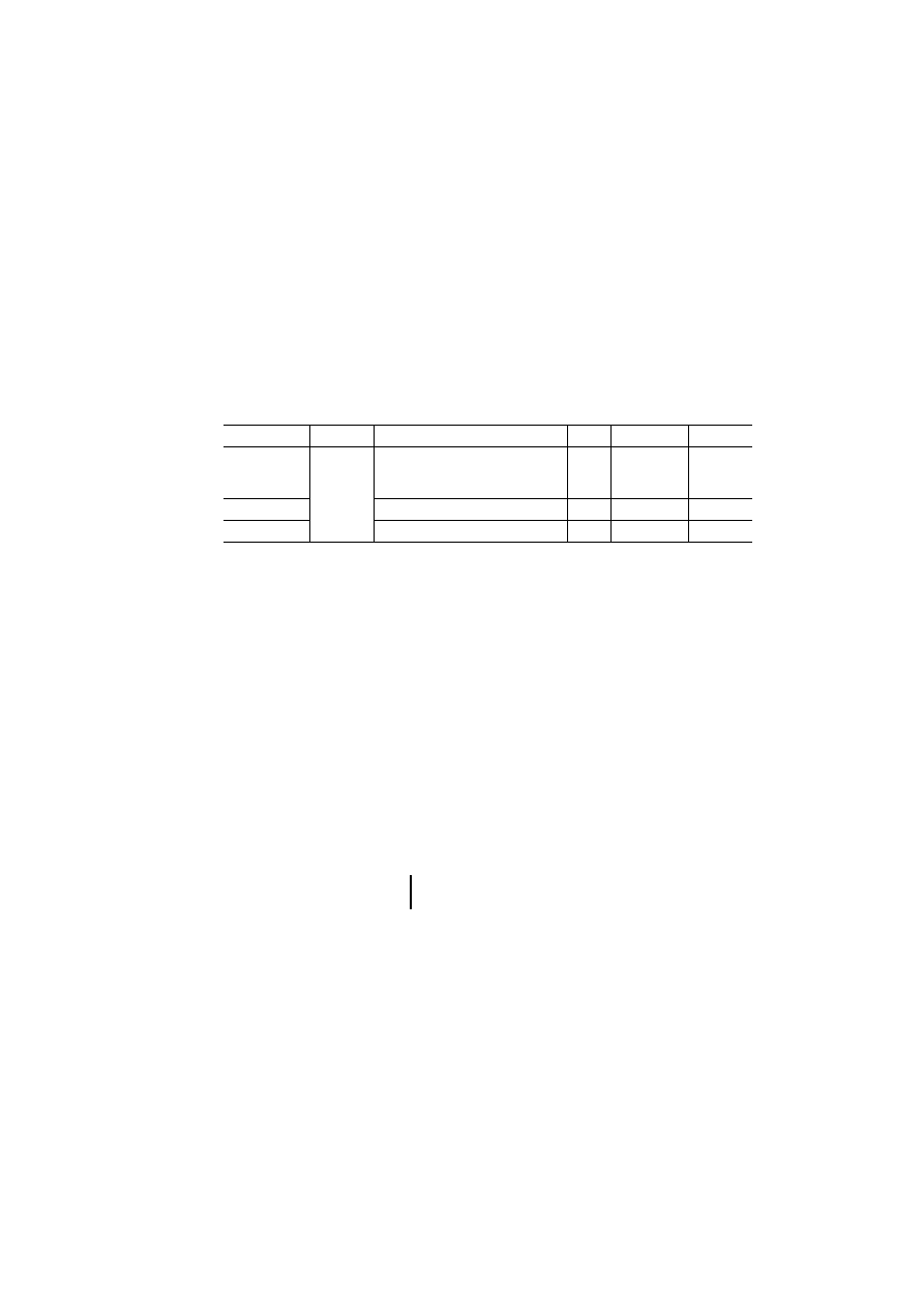
Table 1: Features of the text operator panels
1) For explanation, see legend on next page
2) The MI4-101-KC1, MI4-1x1-KE1 and MI4-131-KH1
units are supplied with a fitted Suconet-K interface.
3) Electromechanical keypads can be fitted
MI4
Display
Operator
panel
Interfaces
1)
Plug-in
interface modules
LC di
spla
y,
tex
t-ba
sed
LC
d
is
pl
ay
, gr
ap
hi
cs
-c
ap
ab
le
Ro
ws
x
characters
Reso
lutio
n in pi
xe
ls
N
umeric keypad
F-ke
ys
wi
th
LED,
labelling
facility
To
tal
number
of k
eys
S
ucom A/configur
at
ion
(PL
C
POR
T)
Su
co
m A
(P
LC
PO
R
T)
C
onf
ig
ur
at
io
n/
pr
in
te
r
(PC/P
R
INT
ER PO
R
T)
S
uconet K (A
UX
POR
T)
2)
PRO
FIBUS DP
(AUX POR
T)
MPI
(A
UX
POR
T)
D
ev
iceNet (A
UX
POR
T)
CA
Nopen (A
UX
POR
T)
Text operator panel (not graphics-capable)
MI4-100-KC1
j
–
2
20 –
–
4
11
j
–
–
j j j j j
MI4-101-KC1
j
–
2
20 –
–
4
11
j
–
–
j j j j j
MI4-100-KE1
j
–
2
20 –
j
9
19
j
–
–
j j j j j
MI4-101-KE1
j
–
2
20 –
j
9
19
j
–
–
j j j j j
MI4-110-KE1
j
–
4
20 –
j
9
19
–
j j
j j j j j
MI4-111-KE1
j
–
4
20 –
j
9
19
–
j j
j j j j j
MI4-130-KH1
j
–
4
40 –
j
16
35
–
j j
j j j j j
MI4-131-KH1
j
–
4
40 –
j
16
35
–
j j
j j j j j
Text operator panel (graphics-capable)
MI4-110-KC1
–
j
4
20 120 32
4
11
j
–
–
j j j j j
MI4-110-KD1
–
j
4
20 120 32
j
9
19
j
–
–
j j j j j
MI4-110-KG2
–
j
4
20 120 32
j
12
35
j
–
–
j j j j j
MI4-110-KG1
–
j
4
20 120 32
j
12
35
–
j j
j j j j j
MI4-140-KF1
Handheld
–
j
8
20 120 64
j
9
27
–
j j
j
–
j
–
–
MI4-140-KI1
–
j
8
40 240 64
j
23
47
–
j j
j j j j j
MI4-140-KJ1
3)
–
j
8
40 240 64
j
23
47
–
j j
j j j j j
Features
7
12
/0
3
AWB
-C
2
7-
12
93
GB
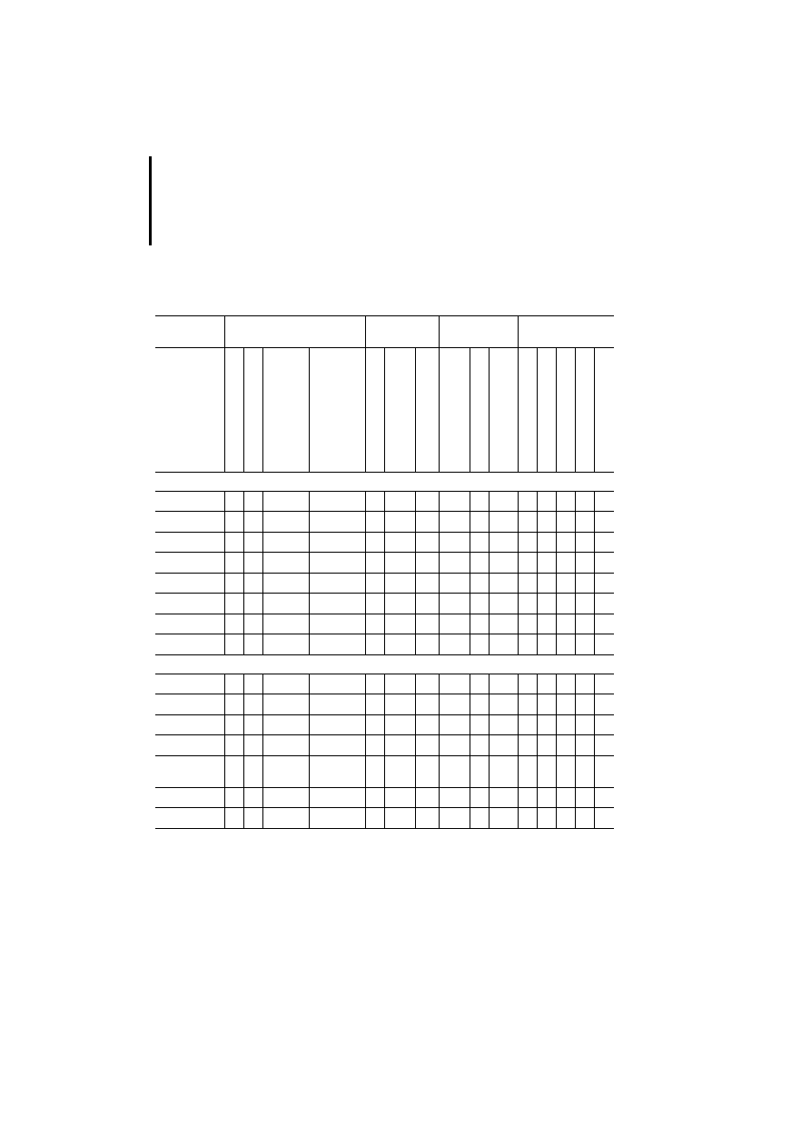
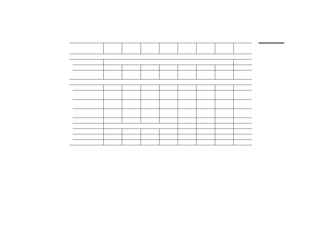
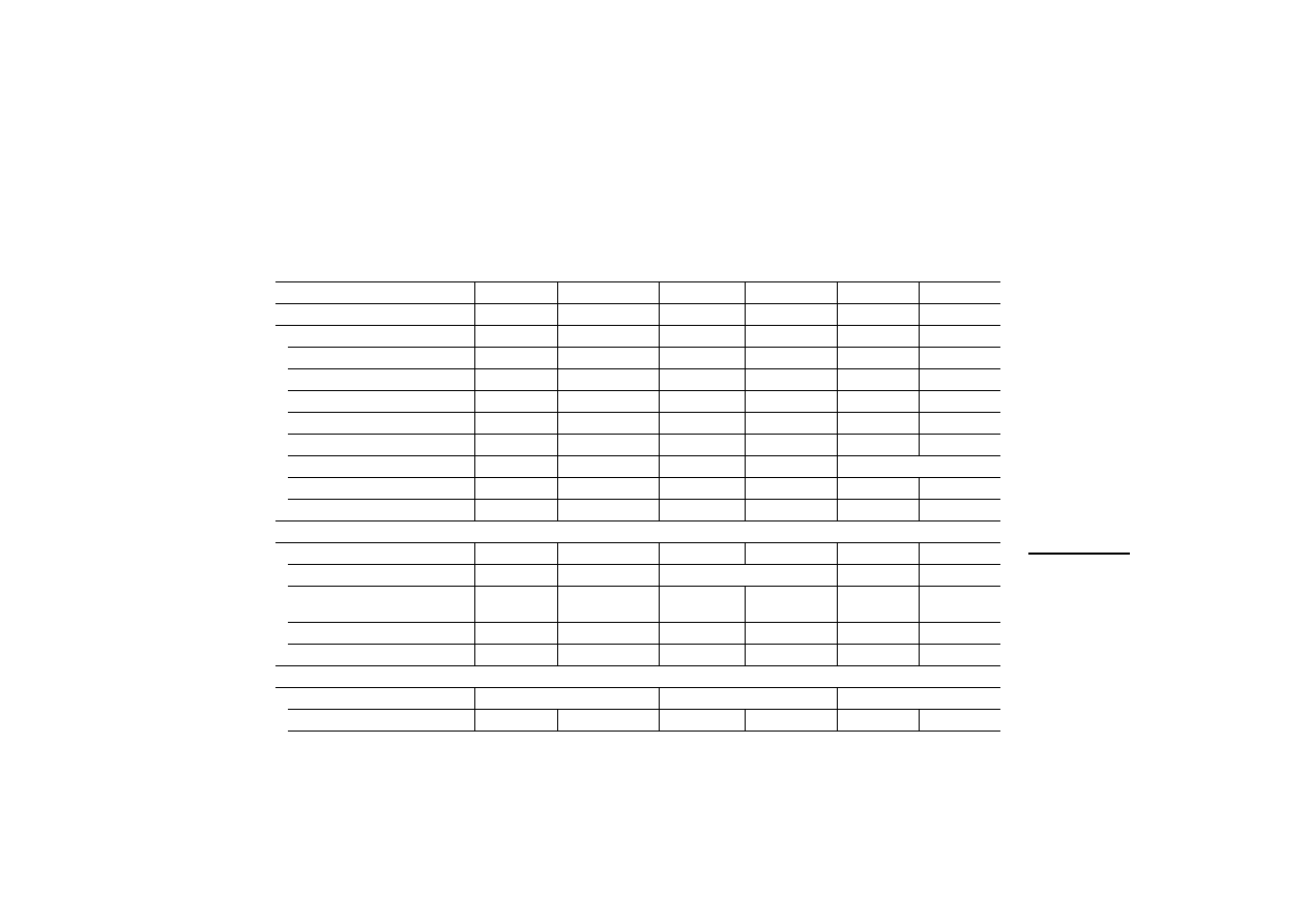
Table 2: Features of the graphic operator panels
1) A PC for uploading or downloading the configuration or
a printer can be connected to the PC/PRINTER PORT.
To the PLC PORT, the PLC for data transfer with the
Sucom A protocol is connected. On devices without
PC/PRINTER PORT, the PC or printer can also be
connected to this port with an adapter.
To the AUX PORT, the PLC for data transfer using the
respective bus protocol is connected.
2) The MI4-151-KF1 and MI4-451-KF1 units are supplied
with a fitted Suconet-K interface.
MI4
Display
Control panel
Inter-
faces
1)
Plug-in interface
modules
LCD p
a
ss
ive mon
o
ch
rome
LCD p
a
ss
ive colou
r
TFT
Ro
ws x characters
Disp
lay s
ize in i
n
ches
Resolut
ion in pixels
Res
istiv
e tou
ch
Numeric keypad
F-keys wit
h
LED, label
ling facility
To
tal number of
keys
Sucom A (PLC POR
T
)
C
o
nf
ig
ura
tion/
prin
te
r (P
C/
PRIN
TE
R
POR
T
)
Sucone
t K (AUX POR
T
)
2)
PROFIB
US
DP (AUX POR
T
)
MPI (
A
UX POR
T
)
Devi
ceN
e
t (AUX POR
T
)
CAN
o
pen
(A
UX POR
T
)
MI4-151-KF1
j
16
40
5,6
320
240
j
10
37
j j
j j j j j
MI4-451-KF1
j
16
40
5,6
320
240
j
10
37
j j
j j j j j
MI4-150-KI1
j
16
40
5,6
320
240
j
33
57
j j
j j j j j
MI4-450-KI1
j
16
40
5,6
320
240
j
33
57
j j
j j j j j
MI4-170-KH1
j
30
80
10,4 640
480
j
23
50
j j
j j j j j
MI4-570-KH1
j
30
80
10,4 640
480
j
23
50
j j
j j j j j
Display Units And Operator
Panels
8
12
/0
3
AWB
-C
2
7-
12
93
GB
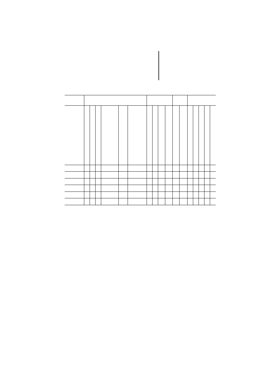
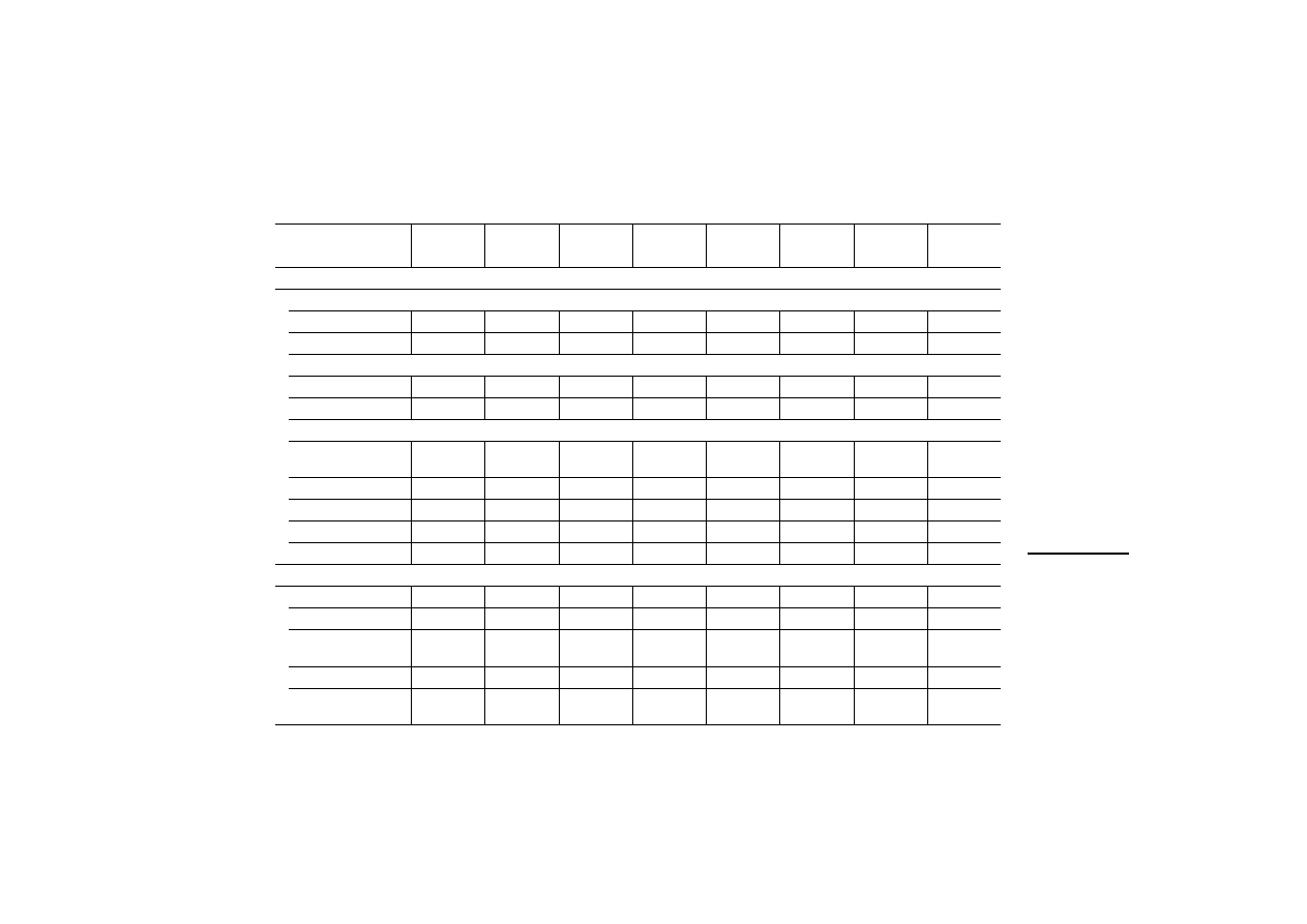
Table 3: Features of the touch operator panels
MI4
Display
Control
panel
Inter-
faces
1)
Plug-in interface
modules
LCD pas
sive m
o
nochrome
LCD pas
sive col
o
ur
LCD active
TFT
Ro
ws
x characte
rs
Display size in inches
Re
solut
ion i
n
pixels
Re
sist
ive t
o
uch
F-keys wi
th LED,
labelling facility
To
tal numbe
r of keys
Su
com A (PLC PO
R
T
)
Co
nfigura
tion/print
e
r
(PC/PRINTER POR
T
)
Su
con
e
t K (AUX POR
T
)
2)
PROFIBUS DP (AUX POR
T
)
MPI (
A
U
X
PO
R
T
)
Dev
iceNet (AU
X
POR
T
)
CA
Nopen
(
A
UX POR
T
)
MI4-151-TA1
j
16
40
5,6
320
240
j
–
–
j j
j j j j j
MI4-451-TA1
j
16
40
5,6
320
240
j
–
–
j j
j j j j j
MI4-161-TC1
j
25
80
9,5
640
400
j
2
9
j j
j j j j j
MI4-471-TC1
j
30
80
10,4
640
480
j
2
9
j j
j j j j j
MI4-130-TA1
j
16
40
3,8
320
240
j
–
–
–
3
–
j j j j j
MI4-140-TA1
j
16
40
5,6
320
240
j
–
–
j j
j j j j j
MI4-150-TA1
j
16
40
5,6
320
240
j
–
–
j j
j j j j j
MI4-450-TA1
j
16
40
5,6
320
240
j
–
–
j j
j j j j j
MI4-550-TA1
j
16
40
5,6
320
240
j
–
–
j j
j j j j j
MI4-160-TA1
j
30
80
9,6
640
480
j
–
–
j j
j j j j j
MI4-470-TA1
j
30
80
10,4
640
480
j
–
–
j j
j j j j j
MI4-570-TA1
j
30
80
10,4
640
480
j
–
–
j j
j j j j j
MI4-580-TA1
j
40
100 12,1 800 600
j
–
–
j j
j j j j j
MI4-590-TA1
j
48
128 15
1024
768
j
–
–
j j
j j j j j
1) A PC for uploading or downloading the configuration or a printer can be connected to
the PC/PRINTER PORT.
To the PLC PORT, the PLC for data transfer with the Sucom A protocol is connected. On
devices without
PC/PRINTER PORT, the PC or printer can also be connected to this port with an adapter.
To the AUX PORT, the PLC for data transfer using the respective bus protocol is
connected.
2) The MI4-151-TA1, MI4-451-TA1, MI4-161-TC1 and
MI4-471-TC1 units are supplied with a fitted Suconet-K interface.
3) Port can also be used for engineering.
9
12
/0
3
AWB
-C
2
7-
12
93
GB
2
Engineering
Connections
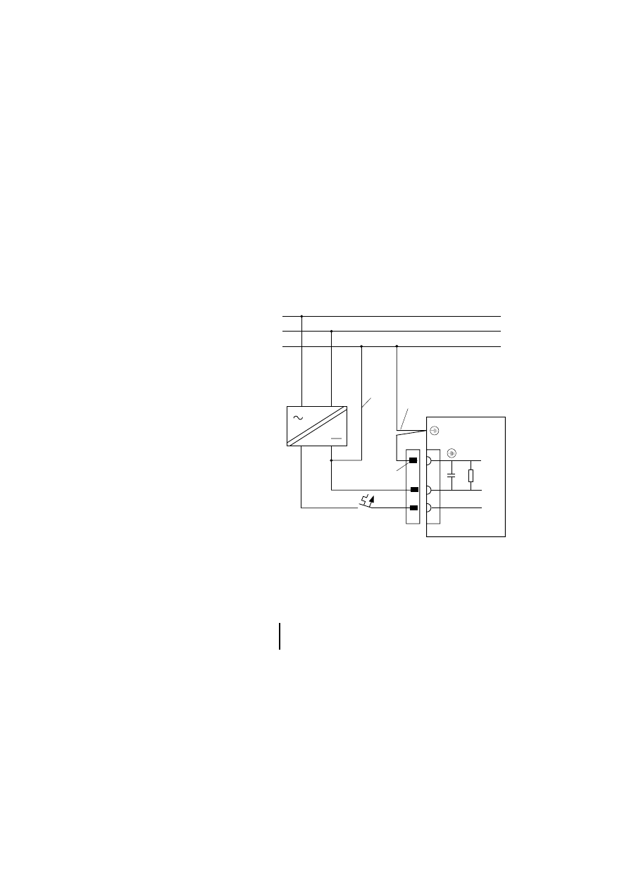
Power supply and grounding
왘 Connect the units as shown in the following
diagrams.
Figure 1: Connection diagram
햲 Earth connection for 0 V line
햳 Device housing earth connection
햴 Power supply plug earth connection
MI 4-...
0 V
+24 V
0 V
+24 V
L1
N
PE
햴
햳
햲
)
For further explanation of the diagram legend,
see page 11.
Engineering
10
12
/0
3
AWB
-C
2
7-
12
93
GB
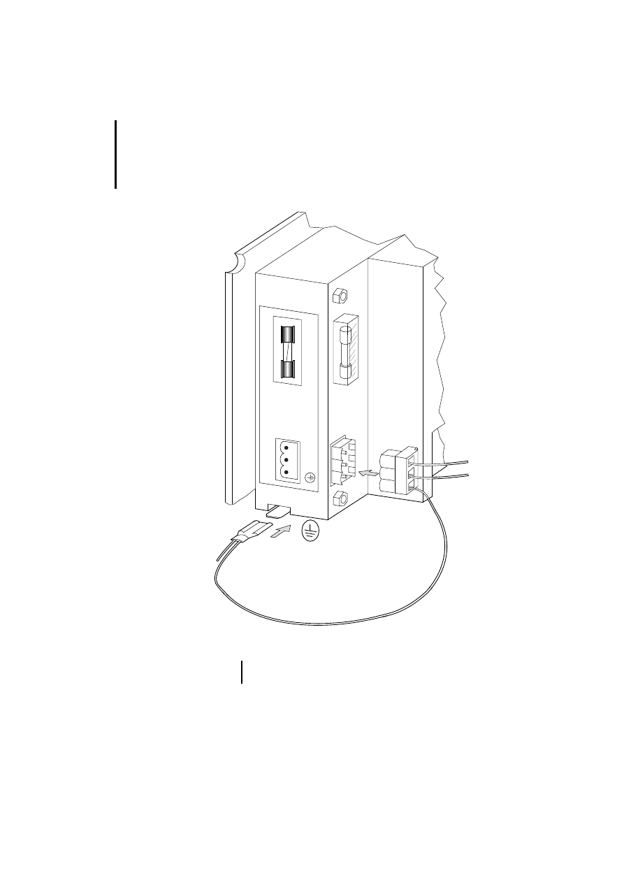
Figure 2: Connecting the power supply and earthing
햴
2A R
24V DC
2
1
3
0V 24V
햳
)
Not all devices are fitted with a 2 A fuse.

Connections
11
12
/0
3
AWB
-C
2
7-
12
93
GB
햲 Earthing the 0 volt cable (see Fig. 1)
The units can be operated earthed or unearthed. An
isolation monitoring device must be used for
unearthed operation.
햳 Panel housing earth connection
The panel housing must always be earthed. The
earth connection is located next to the connector
sockets for the power supply. It is indicated by a
sticker bearing the symbol for earth. Use a 6.3 mm
fast-on plug for the power connection.
햴 Power supply plug earth connection
In all cases, connect the earth connection of the plug
to earth. It is connected internally to the 0 V plug
connection through a capacitor-resistor combination
(10 nF, 100 V/1 M
⍀).
Data plug earthing
The data plug housings for MI4 units are earthed.

Engineering
12
12
/0
3
AWB
-C
2
7-
12
93
GB
Data connections
MI4 units are equipped with several connection
ports. The panels differ in their housing design,
electrical data and the protocol they use. The
following illustrations show the pin and socket
assignments of the cable connections to the PC,
printer and PLC.
Overview
Use the table to determine the required connection
type:
)
If you are not using standard cables, you may
only allocate those cable plug pins or sockets
required for the interface in question. Otherwise,
malfunctions may occur.
Connection type
MI4-PORT
Page
MI4 to PLC through ...
Sucom A
PLC
Suconet K
AUX
PROFIBUS-DP
AUX
Siemens MPI
AUX
DeviceNet
AUX
CANopen
AUX
MI4 to PC or printer
PC/PRINTER
PLC (with adapter)
MI4 (hand-held) to PLC through ...
Sucom A
CN3
Suconet K
CN1
Siemens MPI
CN1
MI4 (hand-held) to PC or printer
CN2
Connecting MI4 to PLC
13
12
/0
3
AWB
-C
2
7-
12
93
GB
Connecting MI4 to PLC
SUCOM-A protocol
For serial communication with various PLC systems,
use the PLC PORT of the MI4. The PLC PORT
supports RS 232, RS 485, RS 422 and Current Loop
20 mA. Please use only the specified data cable.
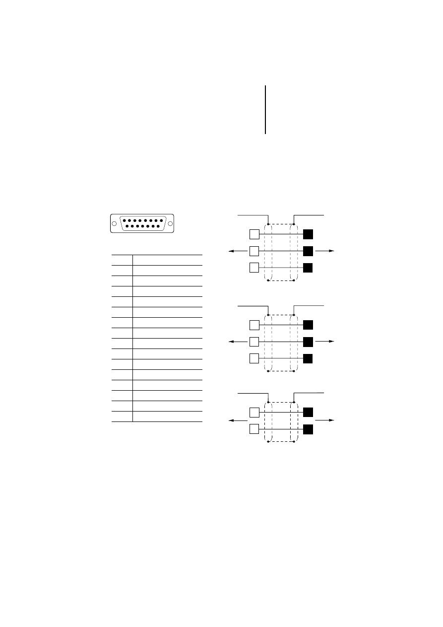
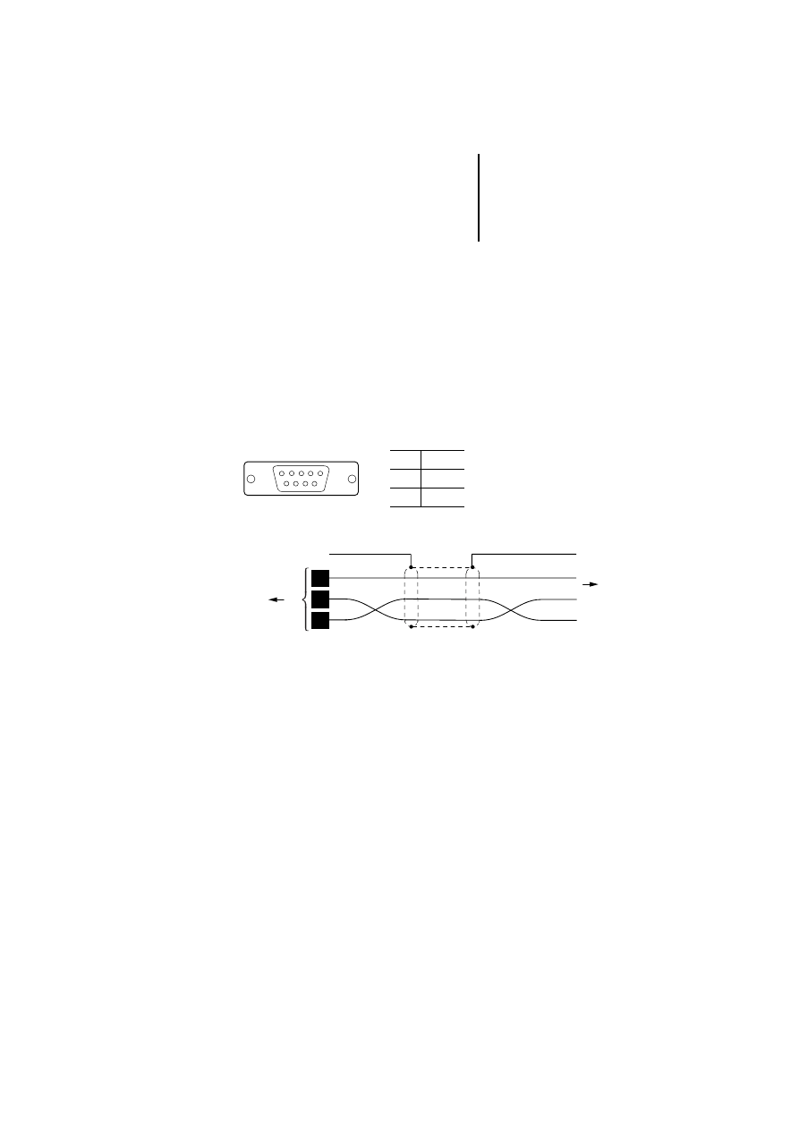
Figure 3: Sucom A communication cable
햲 Connection to the data plug
housing
Q
Plug
q
Socket
1
SUB D
PLC PORT
15
MI4
PLC PORT
MI4
PLC PORT
MI4
PLC PORT
3
5
a
a
5
2
3
ZB4-2B7-KB1
PS4-150
PS4-200
PS4-300
2
3
5
a
a
3
2
5
ZB4-2B3-KB1
PS416
햲
6
14
햲
7
3
ZB4-2B3-KB2
PS416
RS 485
RS 232
RS 232
2
Pin
Function
1
Frame Earth
2
RxD
3
TxD
4
+5 V output (
F 100 mA)
5
GND
6
CHA–
7
CHB–
8
Tx+ 20 mA
9
Tx– 20 mA
10
RTS
11
CTS
12
Rx+ 20 mA
13
Rx- 20 mA
14
CHA+
15
CHB+

Engineering
14
12
/0
3
AWB
-C
2
7-
12
93
GB
Suconet K protocol
Precondition: To operate MI4 units with Suconet K,
the ZB4-501-IF1 interface module must be
connected. The following MI4 units are delivered in
that state:
For all other devices, the Suconet K interface module
must be ordered and fitted separately (see
Section “Interface module”, page 30).
The connection to a PLC with the Suconet K protocol
is made through the AUX PORT of the MI4. The AUX
PORT supports RS 485 communication.
MI4-101-KC1
MI4-151-KF1
MI4-161-TC1
MI4-101-KE1
MI4-451-KF1
MI4-471-TC1
MI4-111-KE1
MI4-151-TA1
MI4-131-KH1
MI4-451-TA1
Connecting MI4 to PLC
15
12
/0
3
AWB
-C
2
7-
12
93
GB
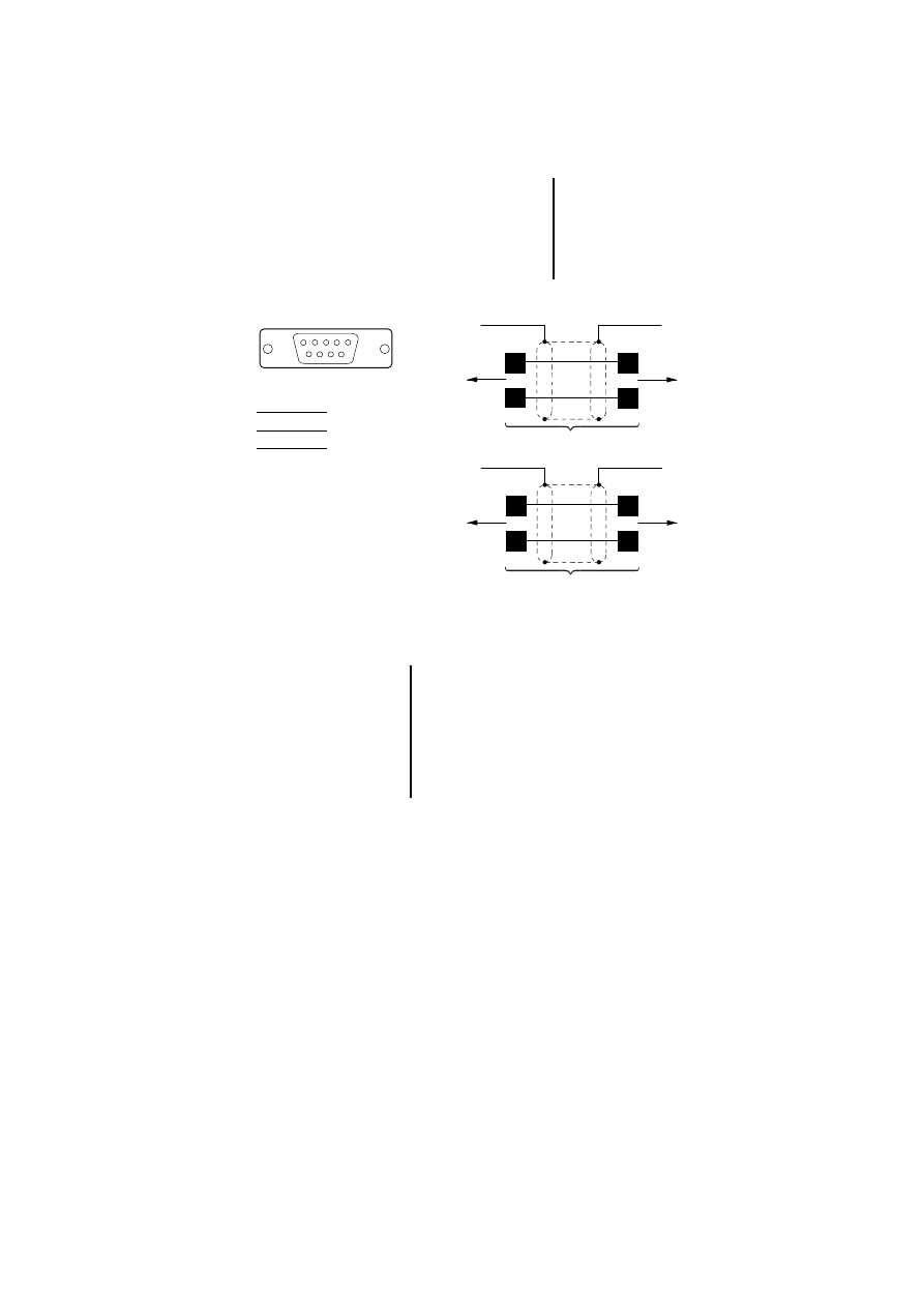
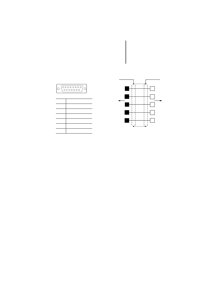
Figure 4: Assignment of the Suconet K communication
cable (cable with plug)
햲 Connection to the data
plug housing
Q
Plug
1
SUB D
AUX PORT
9
1
4
7
3
ZB4-231-KB1
a
a
MI4
AUX PORT
PS4-150
PS4-200
PS4-300
RS 485
3
7
3
7
ZB4-233-KB2
a
a
MI4
AUX PORT
PS416
RS 485
3
A
7
B
)
Bus termination with Suconet K
If the MI4 is the last station on a Suconet line, a
bus terminating resistor should be provided for
this device. The bus terminating resistor for the
MI4 is supplied as a plug and can be ordered
under the type designation ZB4-043-AD1
(Order No. 203512).
Engineering
16
12
/0
3
AWB
-C
2
7-
12
93
GB
PROFIBUS-DP protocol
Precondition: To use the MI4 units with
PROFIBUS-DP, the ZB4-504-IF1/-IF2 interface
module must be connected (see Section “Interface
module”, page 30).
The connection to a PLC with the PROFIBUS-DP
protocol is made through the AUX PORT of the MI4.
The AUX PORT supports RS 485 communications.
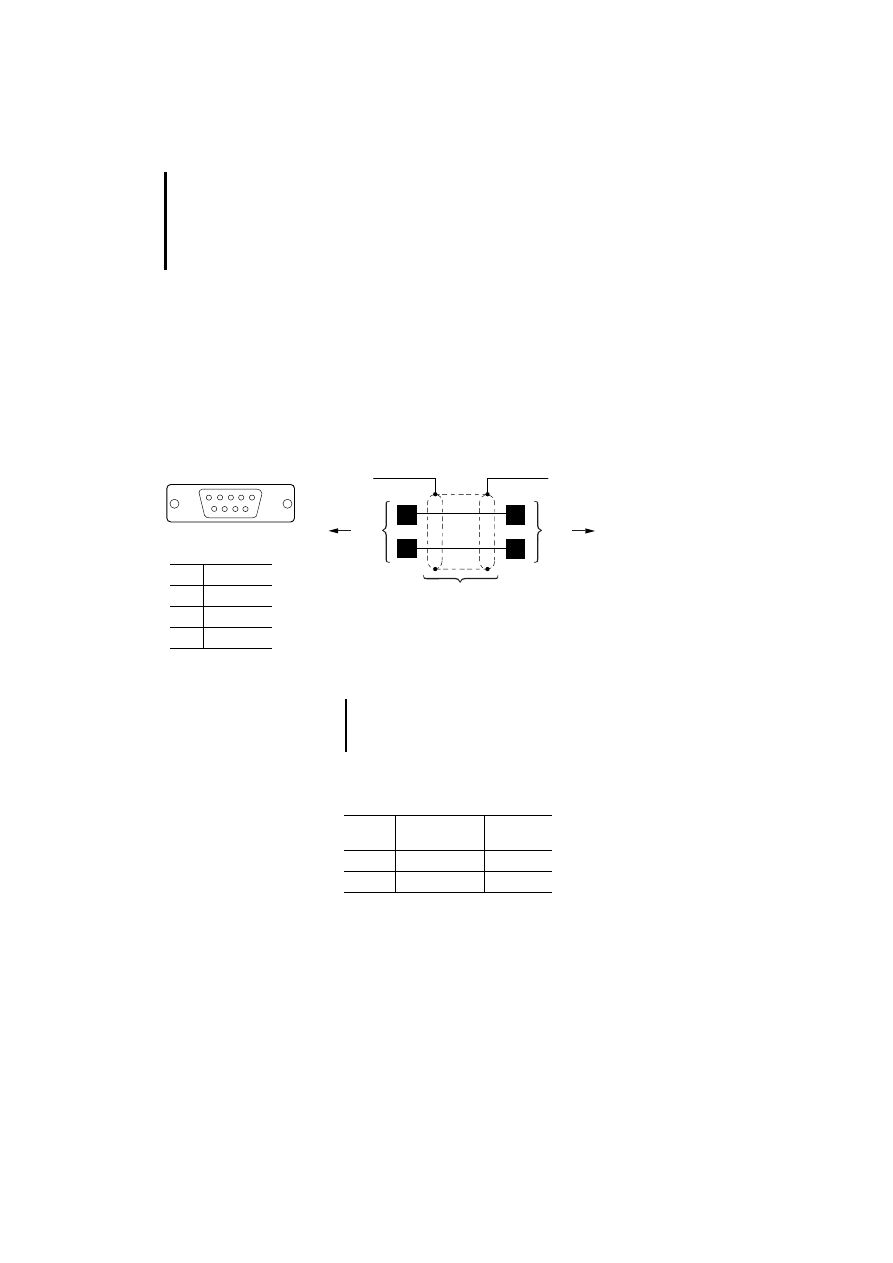
Figure 5: PROFIBUS-DP communication cable
Cables and plugs must be ordered and assembled
separately.
햲 Connection to data plug housing
햳 ZB4-209-DS2
쎱 Plug
1
SUB D
AUX PORT
9
3
8
3
8
ZB4-900-KB1
a
b
a
b
MI4
AUX PORT
PS416-NET-440
LE4-504-BS1
RS 485
3
RxD/TxD-P
5
DGND
6
VP (+5 V)
8
RxD/TxD-N
)
Non-designated pin connectors may not be
assigned because they are specified in the
PROFIBUS-DP standard.
Type
designation
Article No.
Cable
ZB4-900-KB1
206983
Plug
ZB4-209-DS2
206982
Connecting MI4 to PLC
17
12
/0
3
AWB
-C
2
7-
12
93
GB
Siemens MPI
Precondition: For communication through MPI, the
firmware version of the MI4 units must be 4.25 or
later. In addition, the ZB4-505-IF1/-IF2 interface
module (with/without potential isolation) must be
connected (see Section “Interface module”,
page 30).
The connection to a PLC with the MPI protocol is
made through the AUX PORT. The MI4 AUX PORT
supports RS 485 communication.
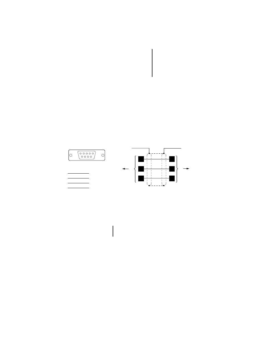
Figure 6: Siemens MPI communication cable
햲 Connection to data plug housing
햳 ZB4-209-DS2 plug
쎱 Plug
1
SUB D
AUX PORT
9
AUX PORT
MI4
a
a
b
b
5
8
3
5
8
3
SPS/PLC/API
3
B
5
GND
8
A
)
For communication through MPI, the
PROFIBUS-DP cable can also be used.
Engineering
18
12
/0
3
AWB
-C
2
7-
12
93
GB
DeviceNet
Precondition: For communication through
DeviceNet, the firmware version of the MI4 units
must be 4.40 or later. In addition, the ZB4-506-IF1
interface module must be connected (see
Section “Interface module”, page 30).
The connection to a PLC with the DeviceNet protocol
is made through the AUX PORT of the MI4. The AUX
PORT supports RS 485 communications.
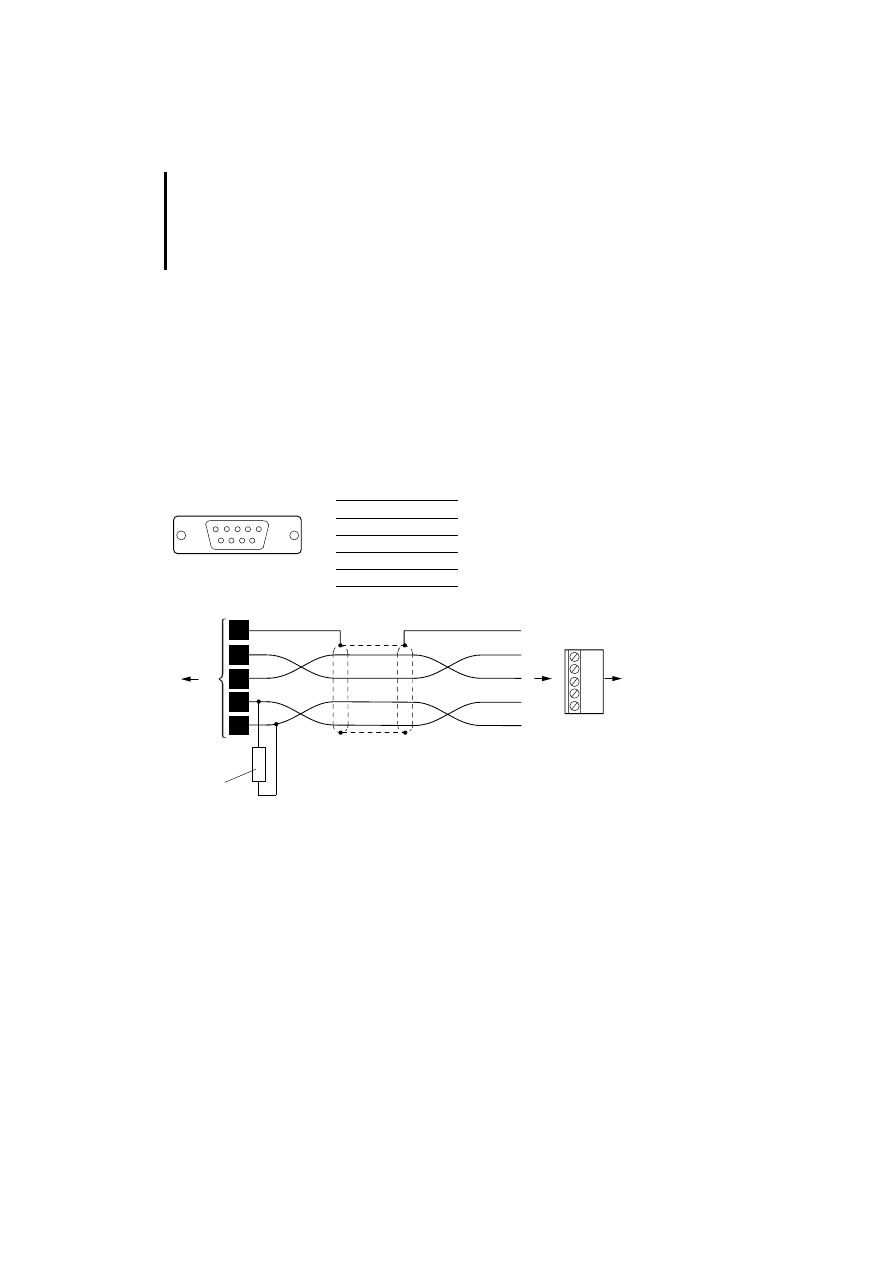
Figure 7: DeviceNet communication cable
햲 ZB4-209-DS1 plug
햳 Bus terminating resistor
1
SUB D
AUX PORT
9
2
CAN_L
3
GND
5
CAN_SHLD
7
CAN_H
9
+24 V (Input)
a
b
5
9
3
Bare
V+(red)
V-(black)
CAN_H(white)
CAN_L(blue)
DeviceNet
7
2
3
5
1
2
3
4
5
1
4
2
121 O G1 %
0.25 W
MI4
AUX PORT
Connecting MI4 to PLC
19
12
/0
3
AWB
-C
2
7-
12
93
GB
CANopen
Precondition: For communication through CANopen,
the firmware version of the MI4 units must be 4.40 or
later. In addition, the ZB4-507-IF1 interface module
must be connected (see Section “Interface module”,
page 30).
The connection to a PLC with the CANopen protocol
is made through the AUX PORT of the MI4. The AUX
PORT supports RS 485 communications.
Figure 8: CANopen communication cable
햲 ZB4-209-DS1
1
SUB D
AUX PORT
9
2
CAN_L
6
GND
7
CAN_H
FG
FG
GND
CANopen
CAN_H
CAN_L
a
9
6
7
2
MI4
AUX PORT

Engineering
20
12
/0
3
AWB
-C
2
7-
12
93
GB
Connecting a PC or
printer to the MI4
Depending on the device model, PCs are connected
either to the PC/PRINTER PORT or the PLC PORT of
the MI4. The different connection types are
described in the following sections.
The PC is connected to the interface for uploading or
downloading the configuration. To be configured
with a PC, the MI4 panels must be in configuration
mode.
Projects can also be downloaded to the graphic or
touch operator panels’ SSFDC memory card through
the ZB4-510-EG1 SSFDC charging device. This has
the advantage that the download is very fast.
The printer can be connected only to the
PC/PRINTER PORT. To connect a printer, set the
communication parameters in the MI4 Configurator
under “Project ➞
Report On Panel Printer ➞ Printer
Setup”.
Connecting a PC or printer
to the MI4
21
12
/0
3
AWB
-C
2
7-
12
93
GB
PC-/PRINTER PORT
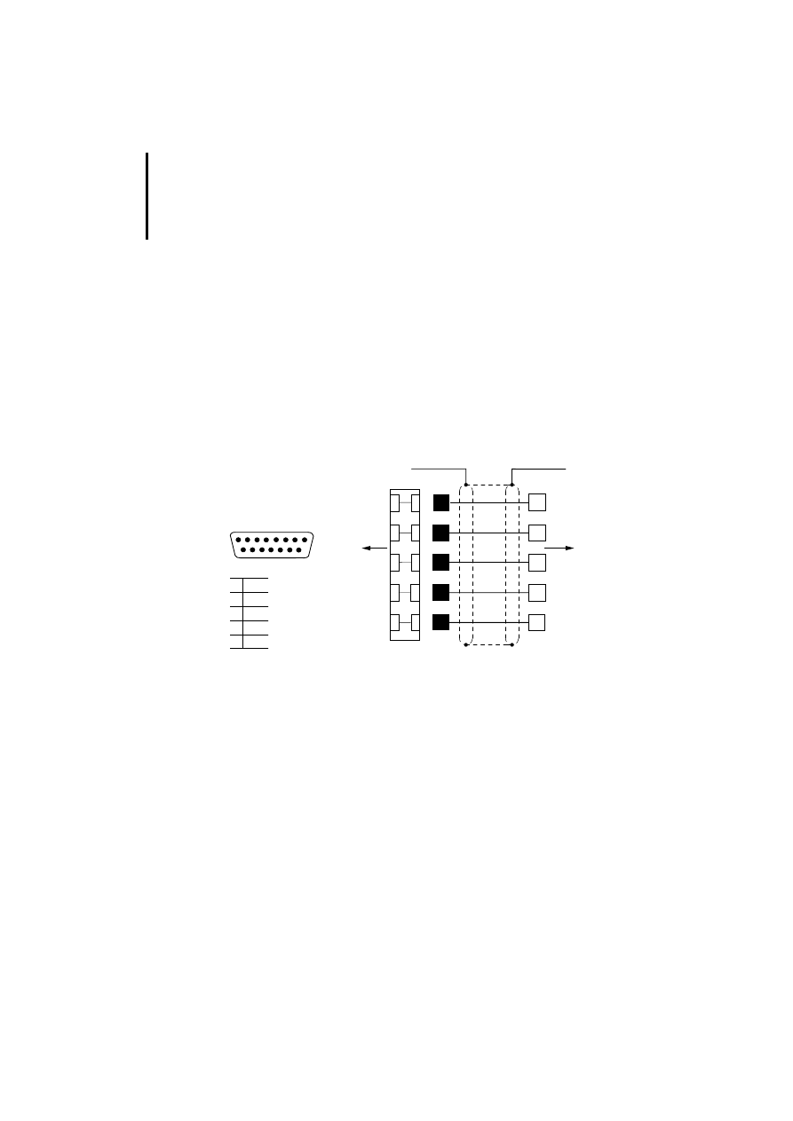
Figure 9: Assignment of the programming cable
햲 Connection to the data plug housing
* On MI4 units without PC/PRINTER PORT, the PC is connected to the PLC PORT
(see next section)
Q
Plug
q
Socket
1
SUB D
PC/PRINTER PORT
15
Pin
Function
2
RxD
3
TxD
4
+ 5 V (max. 100 mA)
5
GND
10
RTS
11
CTS
2
PC/PRINTER PORT
PLC PORT*
PC
3
5
10
11
a
a
3
2
5
8
7
ZB4-24A-KP1
RS 232
Engineering
22
12
/0
3
AWB
-C
2
7-
12
93
GB
PLC PORT
On the following units, connect the PC to the PLC
PORT:
MI4-100-KC1, MI4-101-KC1, MI4-110-KC1,
MI4-110-KD1
MI4-100-KE1, MI4-101-KE1
MI4-110-KG1, MI4-130-TA1
Use the ZB4-24A-KP1 standard cable to connect the
PC. The required adapter is supplied as standard
with the cable.
Figure 10: MI4 – PC connection with adapter
햲 Connection to the data plug housing
Q
Plug
q
Socket
3
2
2
MI 4
PC
3
5
10
11
햲
햲
3
2
5
8
7
ZB 4-24A-KP1
11
10
5 GND
RTS
CTS
RS 232
RxD
TxD
1
SUB D
15
Adapter
PLC PORT
Data interfaces of
MI4-140-KF1 (hand-held)
23
12
/0
3
AWB
-C
2
7-
12
93
GB
Data interfaces of
MI4-140-KF1
(hand-held)
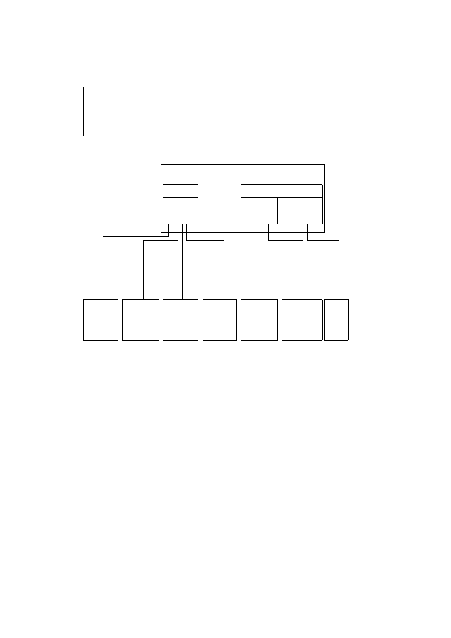
Arrangement and assignment of the adapter
extensions
The adapter extensions in the MI4 hand-held are
arranged as shown in the diagram below. For the
assignments of the adapter extensions, see Table 4:
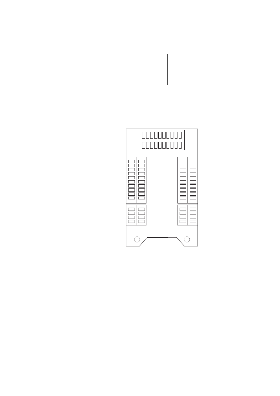
Figure 11: Arrangement of the adapter extensions in the
MI4-140-KF1
CN2
CN5
CN1
CN4
CN3
1 2 3 4 5 6 7 8 9 10
12
3
4
12
3
4
5
6
7
8
9
10
12
3
4
1
2
3
4
567
8
9
10
Engineering
24
12
/0
3
AWB
-C
2
7-
12
93
GB
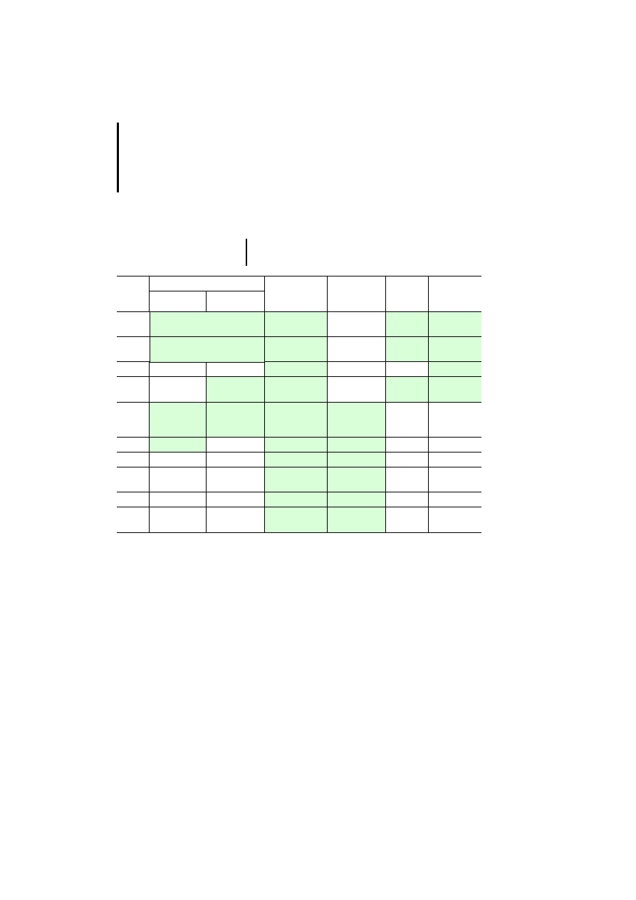
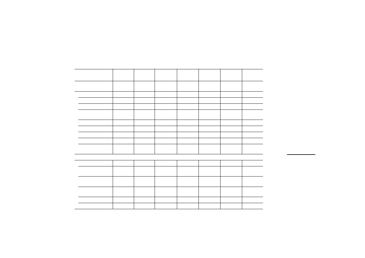
Table 4: Assignment of the adapter extensions in the MI4
hand-held
1) The assignment of the AUX PORT depends on the
connected interface module. Currently, these are the
interface modules for Suconet K and Siemens MPI
(electrically isolated). For further information, please read
the next section.
Delivery state
As supplied, the MI4 hand-held is prewired for
Suconet K and Sucom A communication. The unit is
supplied with a 5 m long cable. The respective
communication module must be ordered separately!
)
The green fields indicate the adapter number
used for each connection.
Plug
No.
CN1 (AUX PORT)
1)
CN2
(PC/PRINTER
PORT)
CN3
(PLC PORT)
CN4
Power
CN5
Additional
signals
Suconet K
MPI
1
GND (brown/pink)
CHA+
Reserved
+24 V DC
(red)
DM Right
(blue)
2
+5 V output (max. 100 mA)
(orange/pink)
CHA–
Reserved
Common
(black)
DM Right
(blue-black)
3
CHB+
Reserved
Reserved
DM Left (cyan)
4
A
CHB–
Reserved
PE
DM Left
(cyan-black)
5
A (yellow/pink) B (yellow/pink)
+ 5 V output
(max. 100 mA)
(green)
+ 5 V output
(max. 100 mA)
(red)
–
–
6
B (green/pink)
GND (grey)
GND (black)
–
–
7
RxD (orange)
RxD (blue/red)
–
–
8
CTS (brown)
CTS (purple/
red)
–
–
9
TxD (white)
TxD (blue/black) –
–
10
RTS (pink)
RTS (purple/
black)
–
–
Data interfaces of
MI4-140-KF1 (hand-held)
25
12
/0
3
AWB
-C
2
7-
12
93
GB
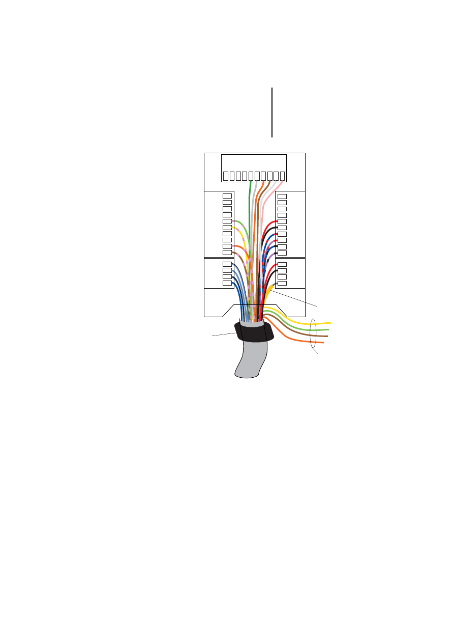
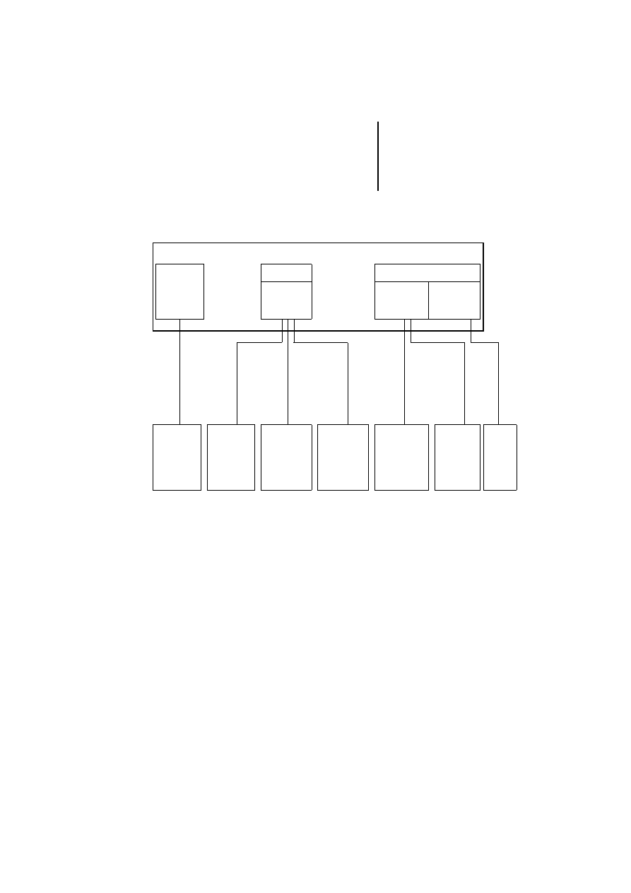
Figure 12: Wiring of the MI4 hand-held as supplied
햲 PE, cable screen
햳 Emergency-Stop switch, only for voltages up to
48 V DC (wire yellow and green cable and brown and
orange cable together)
햴 Ferrite ring required for fault-free device function
CN2
CN5
CN1
CN4
CN3
1 2 3 4 5 6 7 8 9 10
12
3
4
12
3
4
5
6
7
8
9
10
10
9
8
7
43
2
1
6
5
4
3
2
1
a
b
c

Engineering
26
12
/0
3
AWB
-C
2
7-
12
93
GB
Connect MI4
(hand-held) to PLC
Sucom A (through CN3)
PLC connection through Sucom A is preset (see
Section “Delivery state” above). The terminal
assignment on the PLC side is identical to that of the
PLC PORT; see page 13.
Suconet K (through CN1)
PLC connection through Suconet K is preset (see
Section “Delivery state” above). The terminal
assignment on the PLC side is identical to that of the
AUX PORT; see page 14.
CN 1.1 ------- (brown-pink) ---------
CN 1.2 ------- (orange-pink) --------
CN 1.5 ------- (yellow-pink) ----------- Suconet K.3
CN 1.6 -------- (green-pink) ------------ Suconet K.7
Siemens MPI (through CN1)
If the ZB4-505-IF1 MPI communication cable is
connected, the CN1 AUX PORT must be rewired as
follows:
Plug No. 6 (green/pink) to plug No. 4 (see Section
“Delivery state” above)
The terminal assignment on the PLC side is identical
to that of the AUX PORT; see page 17.
CN 1.1 ------- (brown-pink) --------- MPI.5
CN 1.2 ------- (orange-pink) --------
CN 1.4 ------- (yellow-pink) ----------MPI.8
CN 1.5 -------- (green-pink) -----------MPI.3
Connecting the MI4
(hand-held) to PC or
printer (through CN2)
The PC connection is preset (see Section “Delivery
state” above).
The terminal assignment on the PC side is identical
to that of the PC/PRINTER PORT or the PLC-PORT;
see page 21.
27
12
/0
3
AWB
-C
2
7-
12
93
GB
3
Installation
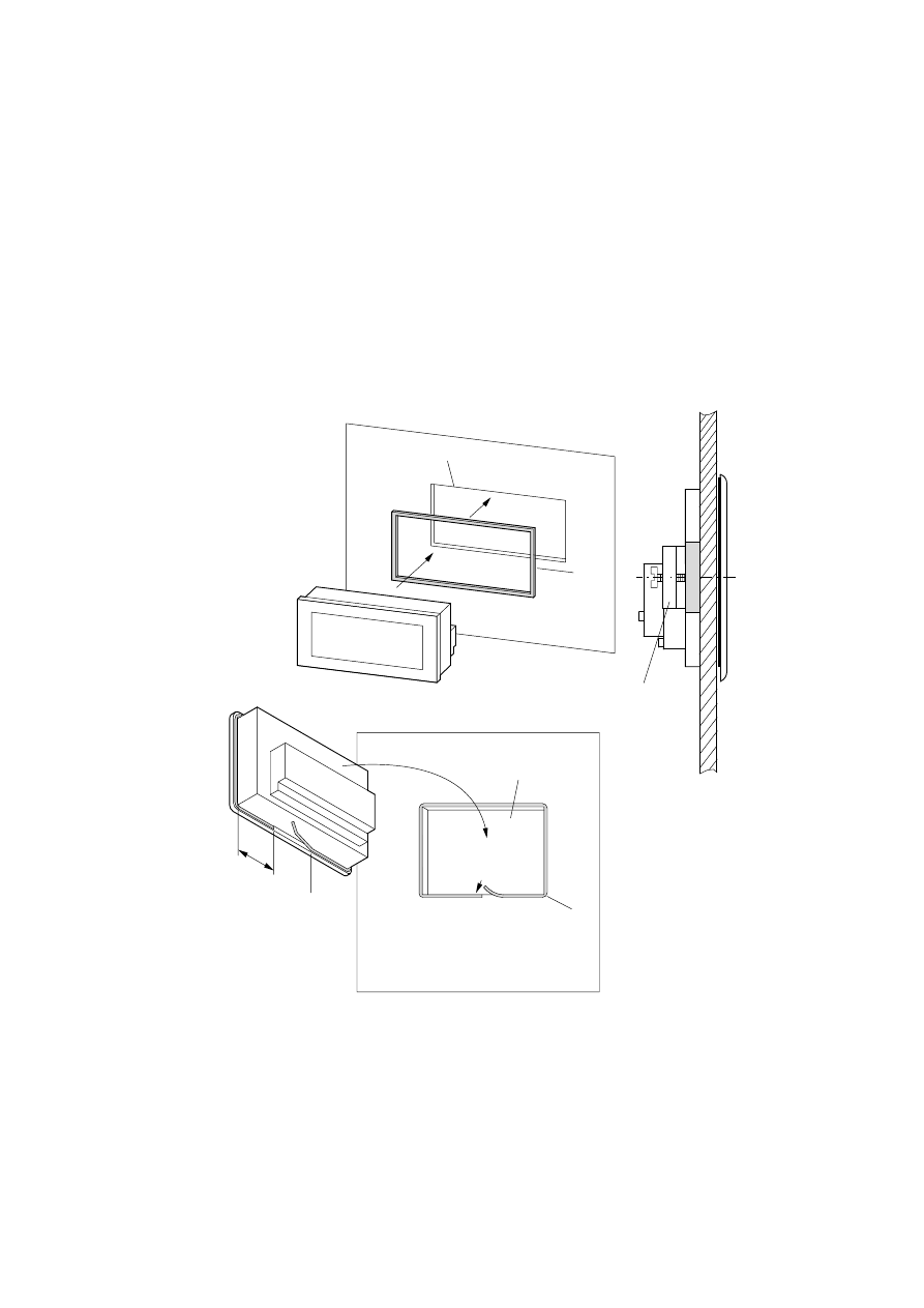
MI4
햲 Installation cut-
out
햳 Rectangular
gasket
햴 Narrow gasket
햵 Wide gasket
(prefitted on
some devices)
햶 Clamping
bracket (if not
present, see next
page)
b
a
MI4-110-KC1
MI4-110-KD1
MI4-100-KC1
MI4-101-KC1
MI4-130-TA1
e
1/3
d
c
a
All other MI4-...
series
Installation
28
12
/0
3
AWB
-C
2
7-
12
93
GB
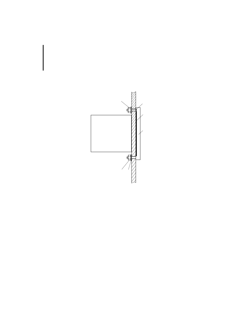
Devices without clamping bracket are mounted with
a frame and four screws.
햲
Frame
햶
Gaskets
햷
Washers
햹
Nuts
햺
Gasket
The drilling dimensions are listed in the table on
page 52.
햹
햹
햲
햷
햺
햶
MI4-140-KF1 (hand-held)
29
12
/0
3
AWB
-C
2
7-
12
93
GB
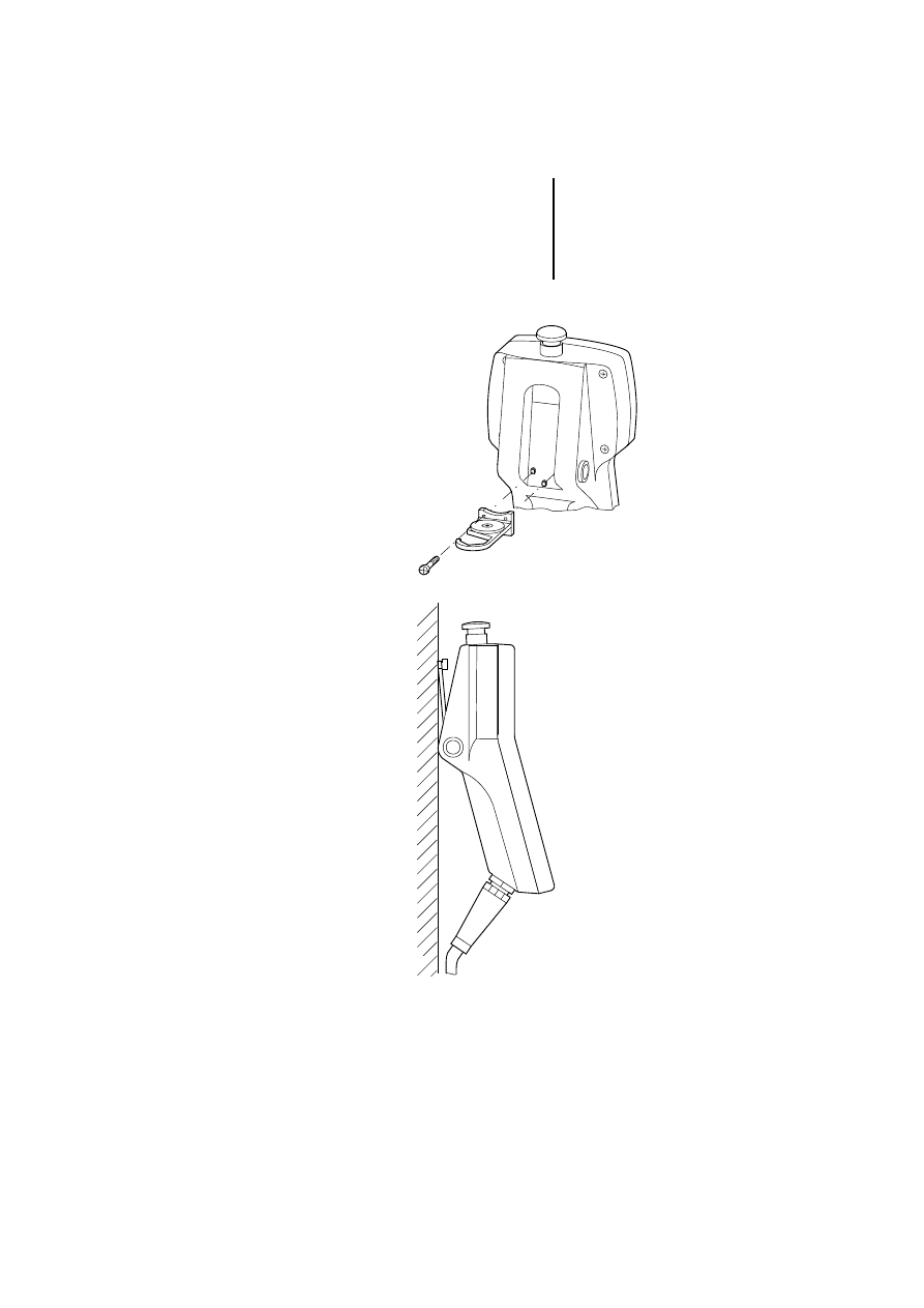
MI4-140-KF1
(hand-held)
Installation
30
12
/0
3
AWB
-C
2
7-
12
93
GB
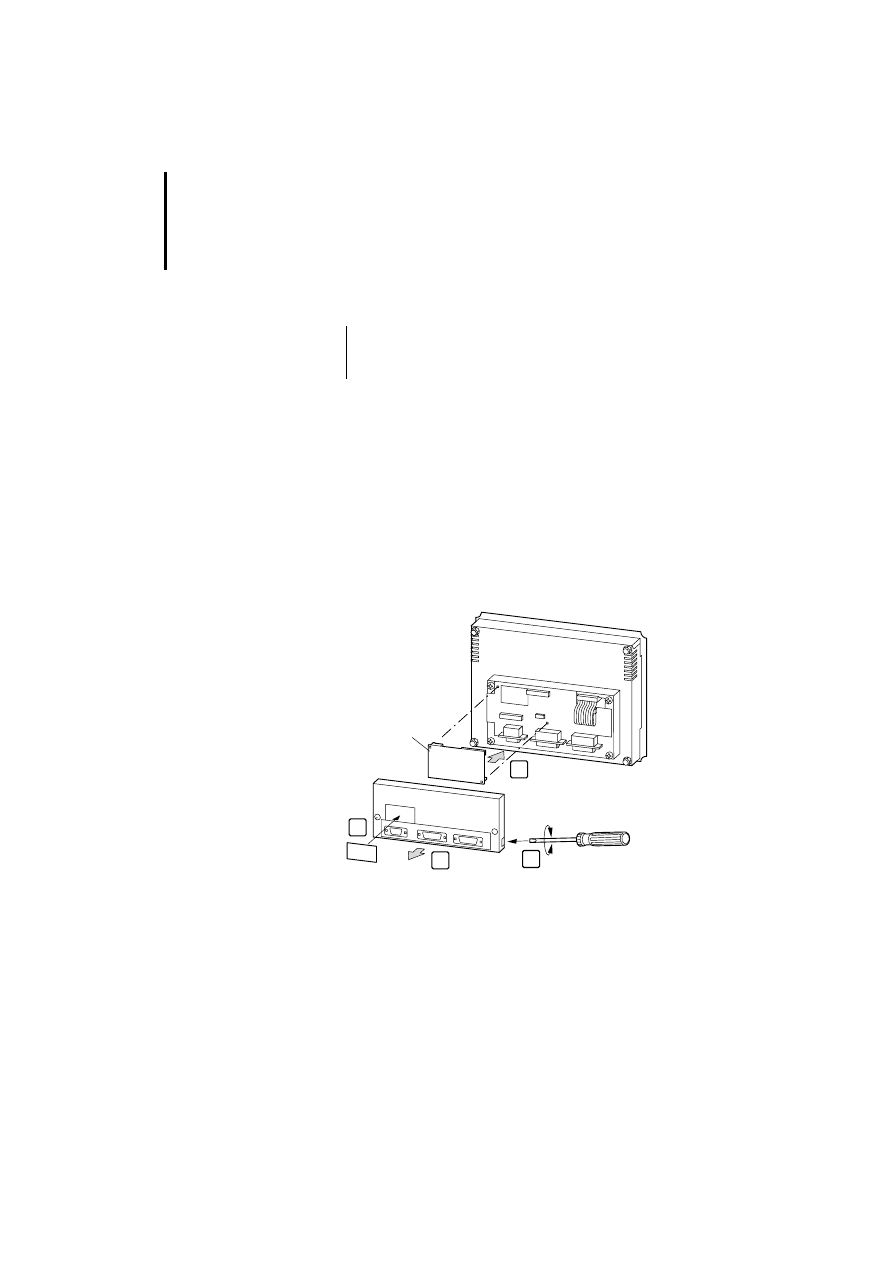
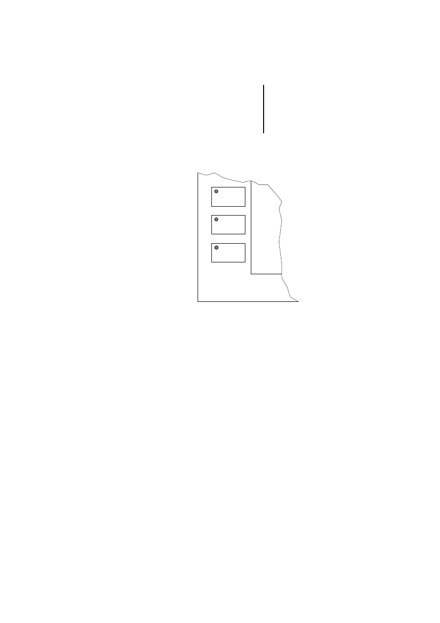
Interface module
MI4...
왘 Remove the fixing screws on the back of the MI4
and lift off the cover. On some models, the cover
has to only be levered off with a screwdriver.
왘 If a module is already fitted, remove it.
왘 Plug the required interface module into the red
connector.
왘 Refit the back cover with the two screws, or snap
the cover back into place.
왘 Attach the accompanying marking label over the
plate labelled AUX PORT.
Figure 13: Installing the interface module
)
During installation of the interface module, the
MI4 must be voltage-free and its reverse side
freely accessible.
ZB4-5xx-IF1/2
1
2
4
3
Interface module
31
12
/0
3
AWB
-C
2
7-
12
93
GB
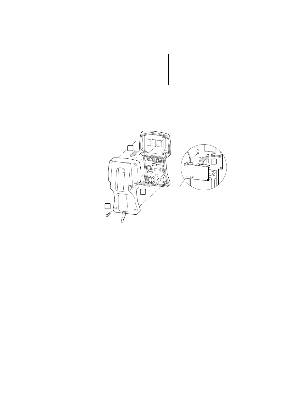
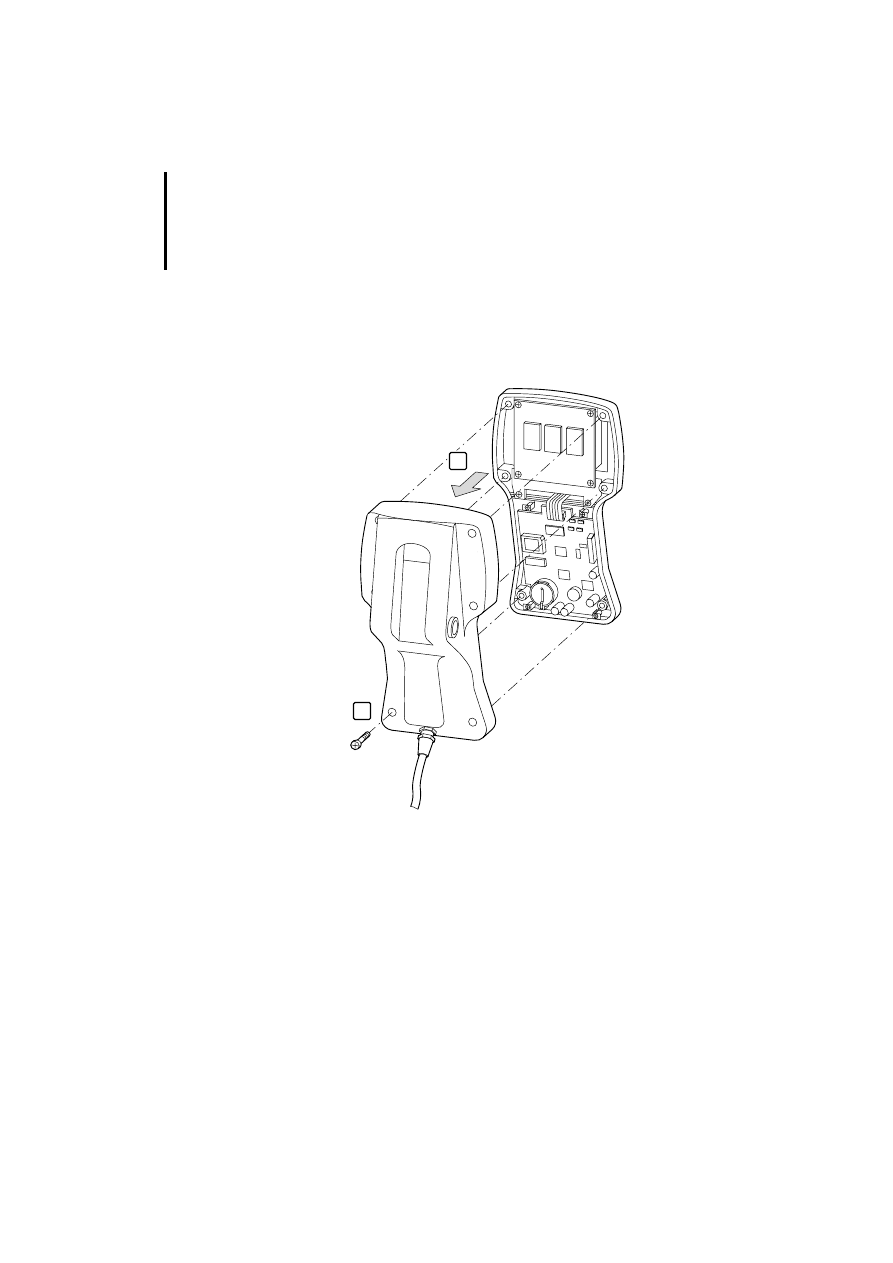
MI4-140-KF1 (hand-held)
왘 Undo the screws and remove the back of the
housing.
왘 Turn the back of the housing towards you and
replace the interface module.
ZB4-501-IF1
ZB4-505-IF1
4
1
2
3

Installation
32
12
/0
3
AWB
-C
2
7-
12
93
GB
Replacing the battery
The battery is used for maintaining the following data
in the event of a power supply failure:
Real-time clock (date and time)
Events list
Recipes
The battery life is about one year. The MI4 units
indicate a low battery charge level in several ways:
Flashing red front plate “FAULT”, “FLT” or
LEDs (depending on device model)
Display in the system menu in the “Battery” field
(BATTERY OK or LOW)
Indication in the control panel status word, bit S 6
(bit S 6 = signal 1)
Replace the battery immediately if any of these
displays is activated. Battery type: Duracell DL 2430
(ZB4-280-BT1, Order No. 203515).
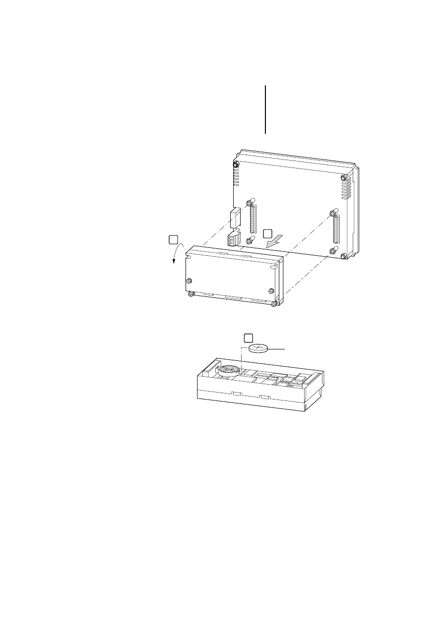
Replacing the battery of the MI4
왘 Switch off the power supply to the device.
왘 Undo the four screws at the back of the
expansion housing.
왘 Remove the housing.
)
The MI4-101-KC1, MI4-100-KC1, MI4-101-KE1,
MI4-100-KE1, MI4-110-KC1 and MI4-110-KG2
units are not battery backed-up.
)
An internal capacitor will maintain the power
supply for 30 seconds while the battery is being
replaced. If this time is exceeded, data will be
lost.
Replacing the battery
33
12
/0
3
AWB
-C
2
7-
12
93
GB
왘 Replace the battery.
왘 Screw the housing back in place.
왘 Switch the power supply back on and check the
battery voltage.
1
2
ZB4-280-BT1
3
Installation
34
12
/0
3
AWB
-C
2
7-
12
93
GB
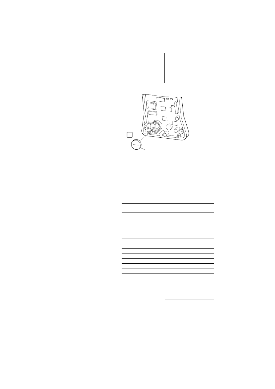
Replacing the battery of the MI4 hand-held
왘 Switch off the power supply.
왘 Undo the four screws at the back.
왘 Remove the housing.
왘 Replace the battery (see next page).
왘 Screw the housing back in place.
왘 Switch the power supply back on and check the
battery voltage.
1
2
Insert labels
35
12
/0
3
AWB
-C
2
7-
12
93
GB
Insert labels
The insert labels are used for labelling the keys. You
can write on the labels and slide them beneath the
keys (row of keys). The insertion slit for the labels is
at the rear of the front panel. Depending on the
device type, two different labelling strip kits are
available:
ZB4-280-BT1
3
ZB4-301-BS1 (Order No.
206859) for ...
ZB4-301-BS2 (Order No.
230610) for ...
MI4-100-KC1
MI4-110-KC1, -KD1
MI4-101-KC1
MI4-110-KG1
MI4-100-KE1
MI4-110-KG2
MI4-101-KE1
MI4-140-KI1
MI4-110-KE1
MI4-140-KJ1
MI4-130-KH1
MI4-150-KI1
MI4-131-KH1
MI4-450-KI1
MI4-151-KF1
MI4-170-KH1
MI4-151-KF1
MI4-570-KH1
MI4-451-KF1
MI4-140-TA1
MI4-151-TA1
MI4-150-TA1
MI4-451-TA1
MI4-450-TA1
MI4-161-TC1
MI4-550-TA1
MI4-471-TC1
MI4-160-TA1
MI4-470-TA1
MI4-570-TA1
MI4-580-TA1
MI4-590-TA1

Installation
36
12
/0
3
AWB
-C
2
7-
12
93
GB
On delivery, blank label strips are fitted to each unit.
With the accompanying labelling software, you can
create user-specific labels and then print them on a
laser printer. The labelling software is included as
standard with the MI4 Configurator and can be
loaded via the Moeller homepage.

37
12
/0
3
AWB
-C
2
7-
12
93
GB
4
Operation
Ambient conditions
Do not expose the equipment to direct sunlight for
extended periods, as this could result in premature
aging of the membrane. Do not let the equipment
come into contact with corrosive substances.
Servicing and
maintaining the panels
Do not use tools to operate the keyboard
(screwdriver or similar). To clean the equipment, use
a soft cloth and a neutral soap product. Do not use
solvents.

Operation
38
12
/0
3
AWB
-C
2
7-
12
93
GB
Configuration
Irrespective of the MI4 model, configuration of the
MI4 panels is always carried out using the MI4
configurator software. The completed configuration
is loaded into the MI4. The following conditions
apply:
The MI4 unit is in configuration mode
1)
(delivery
state).
The PC is connected to the MI4 unit.
The PC port (PORT) COM 1, COM 2, COM 3 or
COM 4 must first be selected in the Configurator
“Options/Communication” menu and the
communications parameters “Baud rate”,
“Parity” and “Stop bit” specified. Transfer rates of
9600, 19200 and 38400 bit/s
can be preselected:
1) If the device is not already in configuration mode,
do the following: Press the Enter key for three
seconds and, in the menu, select Config. On touch
operator panels, touch the screen for three seconds
and select Config.
)
With the ZB4-510-EG1 SSFDC downloader
(Order No. 230617), which can be connected to
the PC’s parallel port, the configuration settings
can be downloaded to the SSFDC memory card
in just a few seconds.
Key functions
39
12
/0
3
AWB
-C
2
7-
12
93
GB
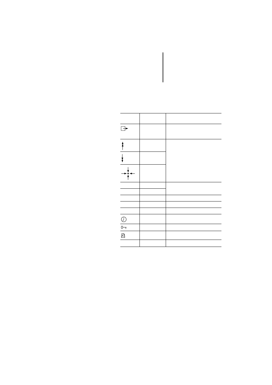
Key functions
This section contains a listing of the possible key
functions of all MI4 panels.
Table 5: Possible key functions and their meaning
With the numeric keys 0 to 9, you can input numerical
values. Some of the keys contain an additional
symbol. Depending on the operating mode, either
the numeric keypad or the symbols are active.
Keys/
symbols
Designation
Function
ESC
Returns to page mode without
selecting ROW or EXIT in the system
menu
PG_UP
In page mode, this function can be
defined with the help of the macro
editor
PG_DOWN
HOME
Enter
–
Depending on the mode
Clr
–
Info
–
Help
Clear
–
Delete
Ins
–
Insert
DATIME
Date/time
PASSWORD
Enter password
⫾
–
+/– Input a positive or negative value

Operation
40
12
/0
3
AWB
-C
2
7-
12
93
GB
Key functions depending on the operating mode
The functions are dependent on the operating mode.
Only the standard functions are described here.
These functions – with the exception of functions
available in configuration mode – can be modified,
deleted or extended in the MI4 Configurator using
the keyboard macro editor.
Configuration mode (CONFIG)
1
If you have programmed the Enter key by mistake, change
to configuration mode as follows:
On MI4 with touchscreen: With a finger of the left hand,
press the centre of the left half of the touchscreen. Keep
the finger on the touchscreen and switch the power supply
on. With a finger of the right hand, tap the right half of the
touchscreen once every second until configuration mode is
selected.
On MI4 without touchscreen: Keep any three keys pressed
at the same time and switch the 24 V power supply on.
Keep the keys pressed until the MI4 is in configuration
mode.
)
Some panels do not have a “Clear” key; the
corresponding function can, however, be called
up by simultaneously pressing the “
←
” and “
→
”
keys.
Enter
1
View the type and version of the
communication driver
Enter
Pressed for 2 seconds:
Return to application mode, provided a
communication driver which is ready for
operation and a valid project have been
saved in the device (the key must be
pressed for two seconds).
Key functions
41
12
/0
3
AWB
-C
2
7-
12
93
GB
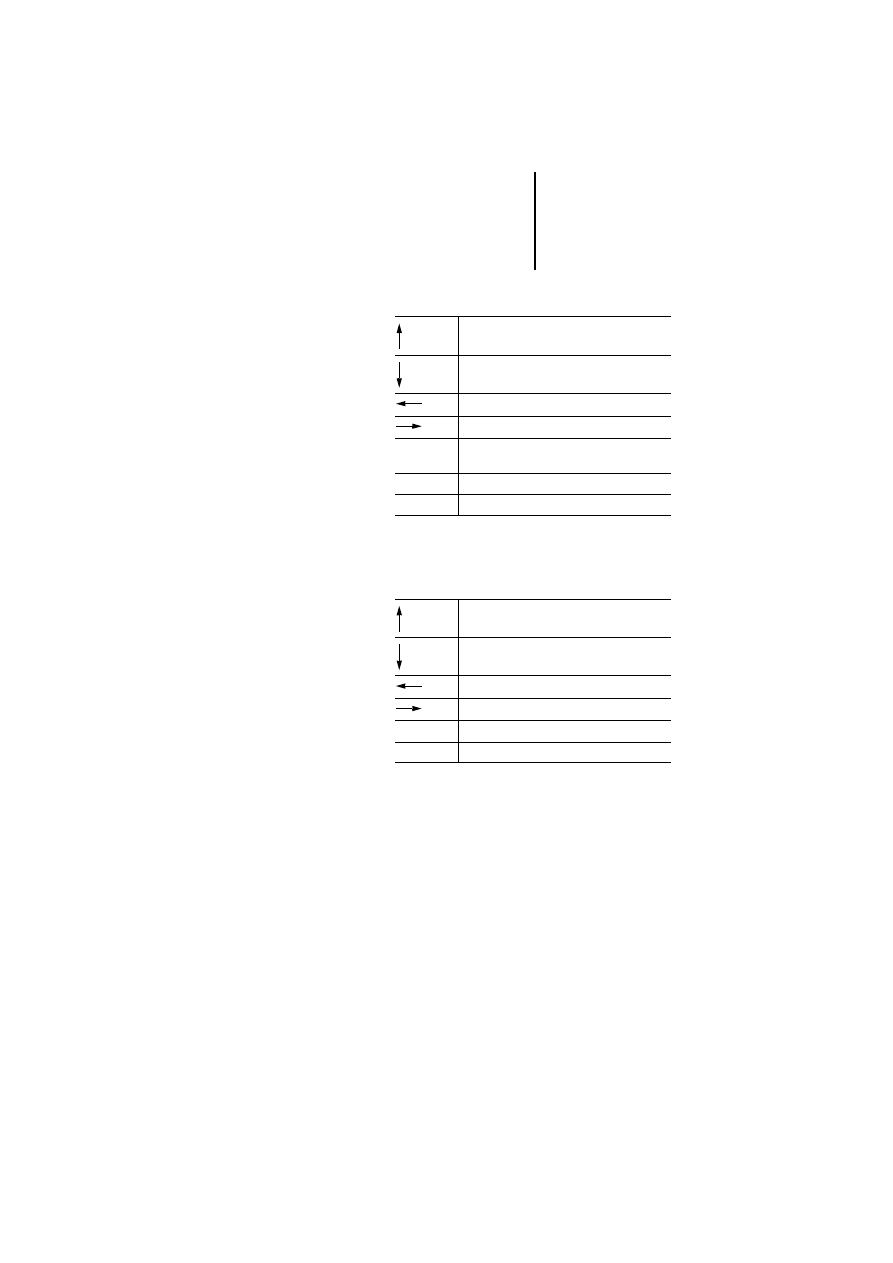
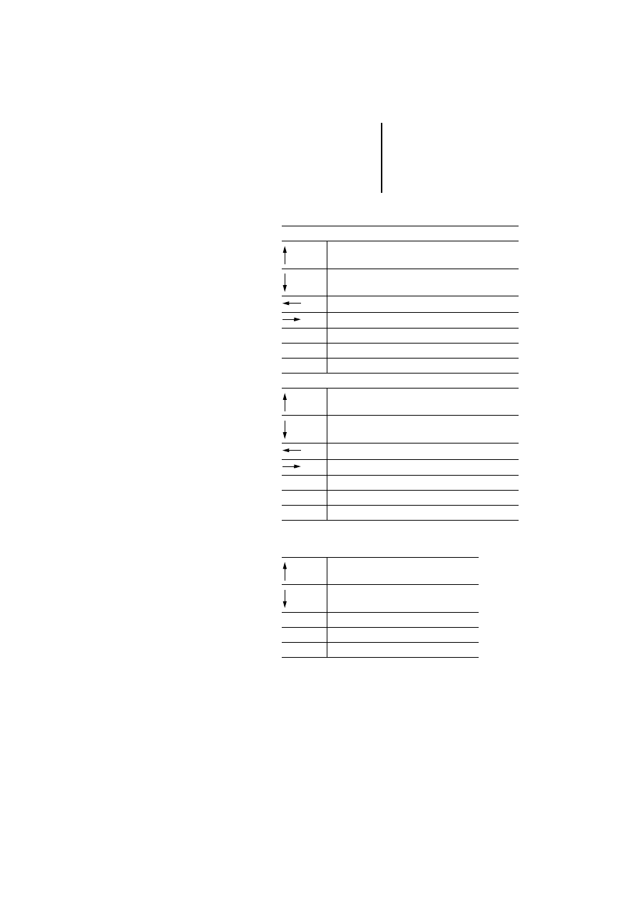
Page mode (PAGES)
1) Not all models have this key. The corresponding
function can be assigned with the keyboard macro
editor.
Command menu (COMMAND)
Scroll page up
Scroll page down
Previous page
Next page
Enter
Pressed for 2 seconds:
Recall the command menu
Ins1)
Data input mode
Prn
1)
Print page/cancel printing
Selection up
Selection down
Selection left
Selection right
Enter
Activate selection
Clear
Return to page mode

Operation
42
12
/0
3
AWB
-C
2
7-
12
93
GB
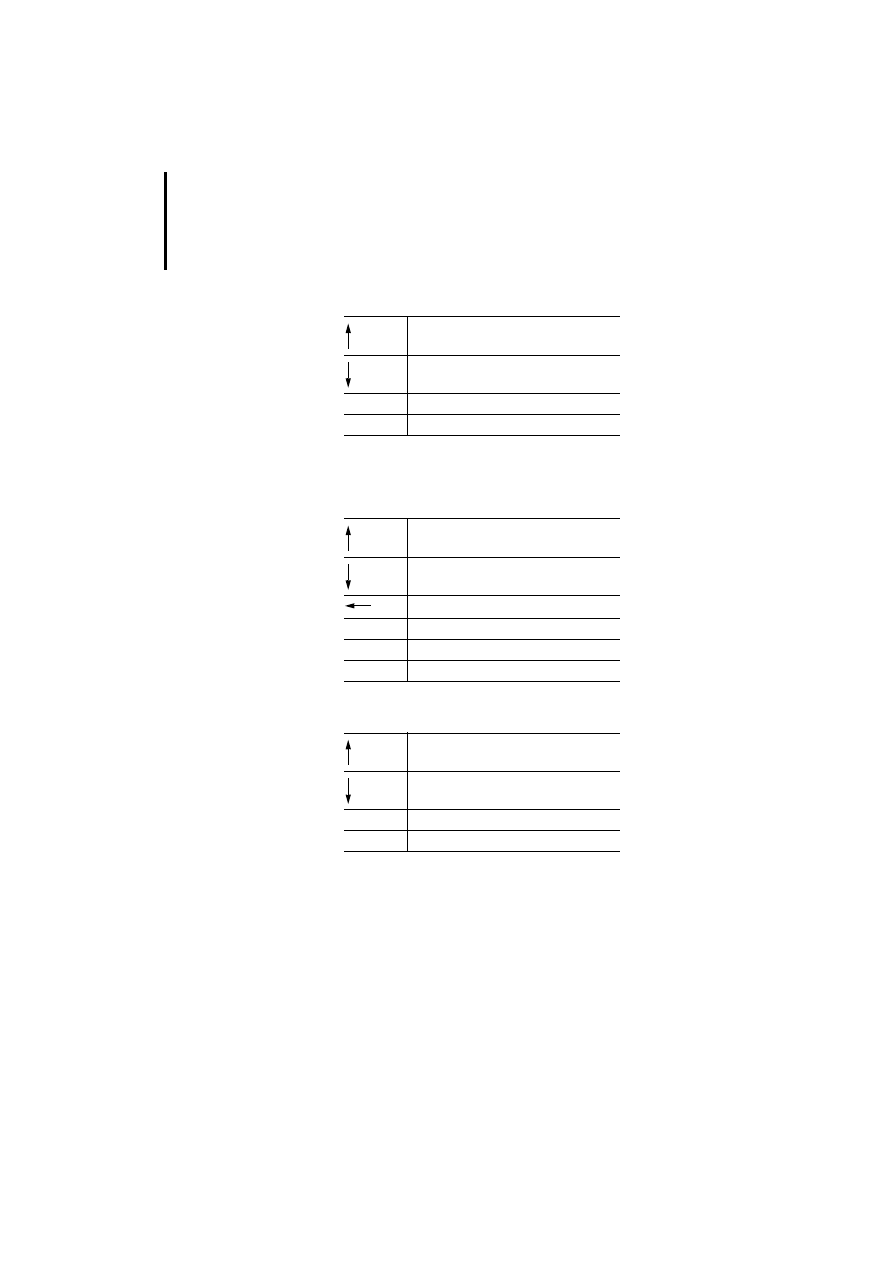
System menu (SYSTEM)
1) Numeric keys are not available on all models. A
numeric value can be entered in these cases using the
arrow keys and the keyboard macro editor. To do this,
use the left and right arrow keys to select the required
digits and change them with the up and down arrows.
Selection up
Selection down
Activate command
Activate command
Enter
Return to page mode if EXIT was selected
Clear
Return to page mode
Key functions
43
12
/0
3
AWB
-C
2
7-
12
93
GB
Data entry mode
1) If not present, see legend on page 42
Alarm mode (ALARMS)
1) Not all models have this key. The corresponding
function can be defined with the keyboard macro
editor.
Select a data input field:
Go to field in the previous row
Go to field in the next row
Previous field
Next field
Ins (0 to 9)
1)
Preselection of data input field
Enter
Select field for data input
Clear
Cancel input and return to page mode
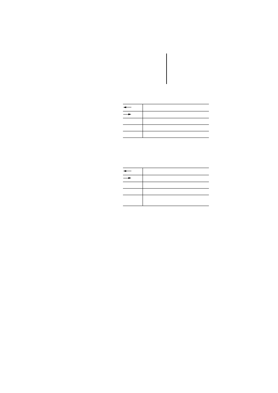
Value input:
Increase value/scroll up ASCII character set/select
previous message
Reduce value/scroll down ASCII character set/select
next message
Move cursor to the left in ASCII fields
Move cursor to the right in ASCII field
0 to 9
1)
Numerical input
Enter
Confirm input and return to page mode
Clear
Cancel input and return to page mode
Previous alarm in the list
Next alarm in the list
Enter
Confirm current alarm (press for 2 seconds)
Clear
Return to page mode
Prn
1)
Print/cancel alarm list
Operation
44
12
/0
3
AWB
-C
2
7-
12
93
GB
Events mode (EVENTS)
1) Not all models have this key. The corresponding
function can be defined with the keyboard macro
editor.
Password input mode (PASSWORD)
1) If not present, see legend on page 42
Time and date input mode (TIME)
Scroll up
Scroll down
Clear
Return to page mode
Prn
1)
Print/close event list
Increases number
Decreases number
Next number
0 to 9
1)
Input of numerical password
Enter
Confirms password
Clear
Cancel input
Increase field value
Decrease field value
Enter
Select field
Clear
Return to page mode
Key functions
45
12
/0
3
AWB
-C
2
7-
12
93
GB
Direct page selection mode (DIRECT PAGE
SELECTION)
1) If not present, see legend on page 42
Direct access mode (ACCESS)
The status of individual marker bytes is shown in
hexadecimal and binary format.
Decreases page
Increases page
0 to 9
1)
Page number input
Enter
Confirm input, go to selected page
Clear
Cancel input, return to page mode
Decrease offset
Increase offset
0 to 9
Numerical offset input
Enter
Select next page, confirm offset input
Clear
Cancel numerical offset input and return to
page mode
Operation
46
12
/0
3
AWB
-C
2
7-
12
93
GB
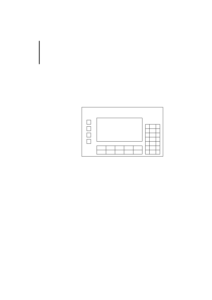
Special features of models MI4-151-KF1 and
MI4-451-KF1
In addition to the ten function keys (which have insert
labels) these two models have another four function
keys located on the left of the display. Their
numbering is shown in the following drawing.
Figure 14: Additional function keys
F14
F13
F12
F11
F1
F2
F3
F4
F5
F6
F7
F8
F9
F10
Key functions
47
12
/0
3
AWB
-C
2
7-
12
93
GB
Special features of models MI4-161-TC1/
MI4-471-TC1
Figure 15: Additional function keys of MI4-161-TC1/
MI4-471-TC1
The configuration of the function keys is shown in the
diagram.
When the shift function is inactive, the top two
function keys are configured as F1 and F2.
When shift is activated they are configured as F3
and F4.
The shift function is activated or deactivated with the
Shift key. An illuminated LED in the shift key
indicates the activated state.
The LEDs of the two function keys can be configured
as required.
shift
F2/F4
F1/F3
Operation
48
12
/0
3
AWB
-C
2
7-
12
93
GB
LED indicators
MI4-100-KC1/MI4-101-KC1
MI4-151-KF1/MI4-451-KF1
MI4-161-TC1/MI4-471-TC1
MI4-100-KE1/MI4-101-KE1
MI4-110-KE1/MI4-111-KE1
MI4-130-KH1/MI4-131-KH1
MI4-151-TA1/MI4-451-TA1
Designation
Colour
Status
Function
DL FL(T)
(one LED)
–
Off
No key pressed/hardware
OK
Green
Flashing
Communication error
On
Key pressed
Red
Flashing
Battery low
On
Hardware fault
Designation
Colour
Status
Function
DL
Green
Off
No key pressed
Flashing
Communication error
On
Key pressed
FLT/fault
Red
Off
Hardware OK
Flashing
Battery low
On
Hardware fault
Designation
Colour
Status
Function
DL
Green
Off
No keys pressed
On
Key pressed
LED indicators
49
12
/0
3
AWB
-C
2
7-
12
93
GB
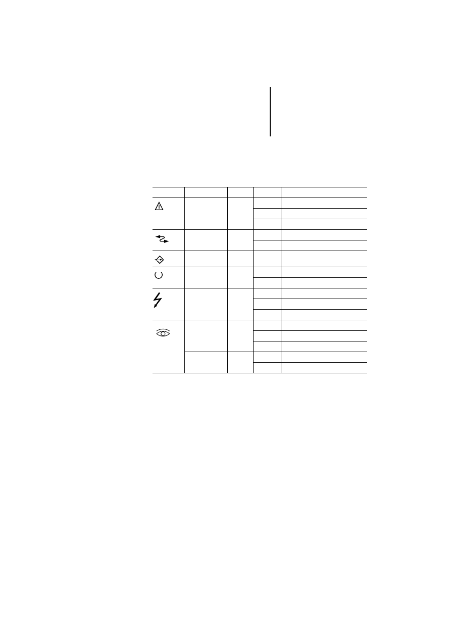
Various models
LED indicators which are marked with a symbol or
text:
Symbol
Designation
Colour
Status
Function
Alarm
Red
Off
No alarm active
On
Alarm active
Flashing
Alarm (confirmation required)
Com
Green
On
Communication OK
Flashing
Communication error
–
Green
–
Programmable with macro editor
Run
Green
Off
Hardware fault
On
OK
Fault
–
Off
Hardware OK
On
Hardware fault
Flashing
Battery low
Red
Off
Hardware OK
On
Hardware fault
Flashing
Battery low
Green
Off
No key pressed
On
Key pressed

Operation
50
12
/0
3
AWB
-C
2
7-
12
93
GB
The values in the table refer to the letters in the
drawings shown on the next page:
a
b
c
d
e
f
MI4-110-KC1
149
109
60
5
136
96
MI4-110-KD1
149
109
53
5
136
96
MI4-110-KG1
141
176
76
5
128
163
MI4-110-KG2
141
176
76
5
128
163
MI4-140-KI1
220
176
71
5
207
163
MI4-140-KJ1
275
220
77
5
262
207
MI4-150-KI1
275
220
80
5
262
207
MI4-450-KI1
275
220
80
5
262
207
MI4-170-KH1
311
276
80
5
292
257
MI4-570-KH1
311
276
80
5
292
257
MI4-130-TA1
149
109
61
5
136
96
MI4-140-TA1
187
147
79
5
176
136
MI4-150-TA1
187
147
91
5
176
136
MI4-450-TA1
187
147
91
5
176
136
MI4-550-TA1
187
147
91
5
176
136
MI4-160-TA1
287
232
91
5
276
221
MI4-470-TA1
287
232
91
5
276
221
MI4-570-TA1
287
232
91
5
276
221
MI4-580-TA1
337
267
91
5
326
256
MI4-590-TA1
392
307
101
5
381
296

51
12
/0
3
AWB
-C
2
7-
12
93
GB
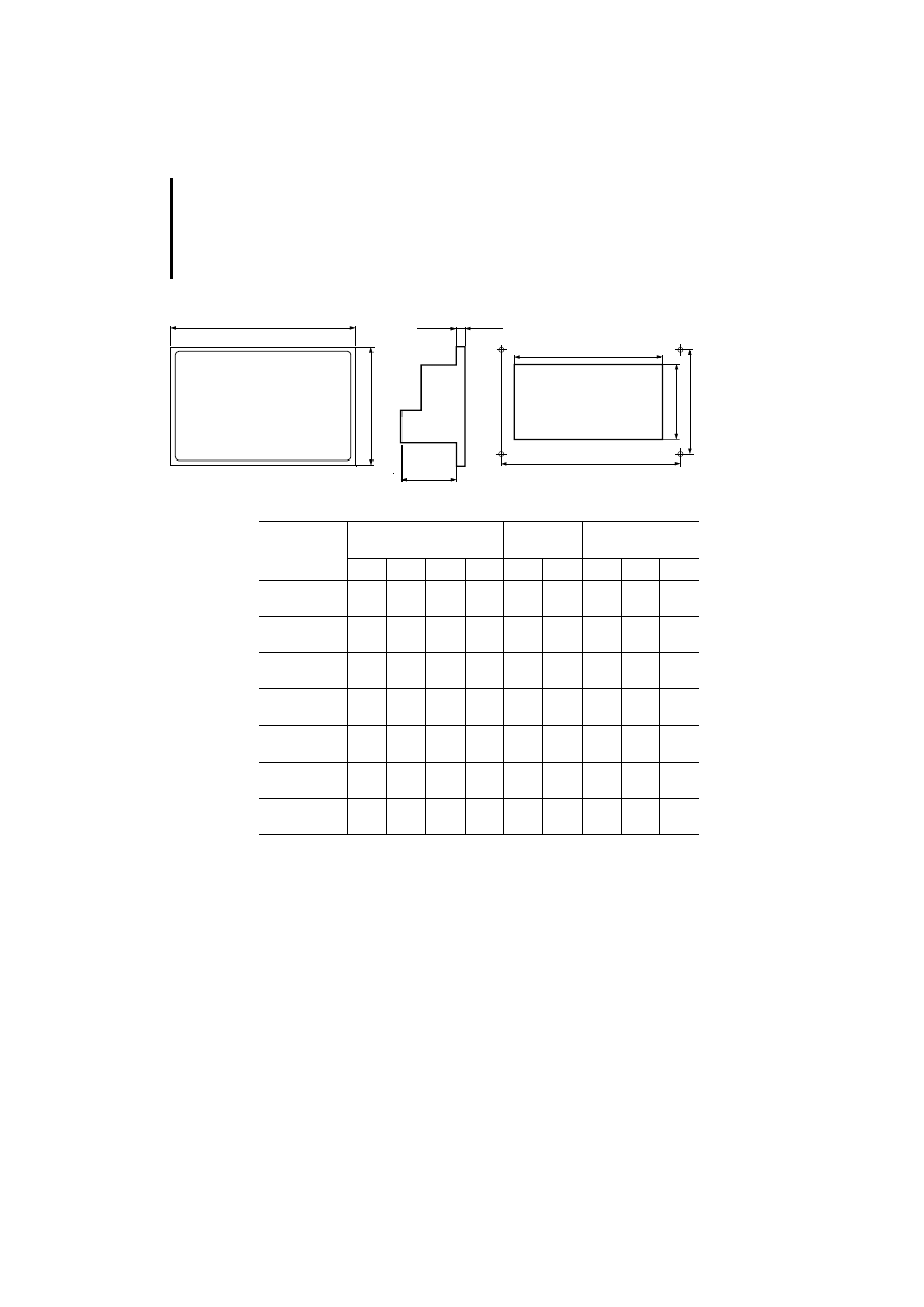
Appendix
Dimensions
)
See the left-hand page for the values
corresponding to device types.
Device dimensions
Fitting dimensions
a
b
c
d
e
f
Operation
52
12
/0
3
AWB
-C
2
7-
12
93
GB
1) These models are secured with screw brackets and
have a fixed frame; the remaining models have a free
frame and are fastened with four screws.
c
b
a
g
h
e
f
d
i
Panel
Unit dimensions in mm
Panel cutout
in mm
Drilling dimensions
[mm]
a
b
c
d
e
f
g
h
i
MI 4-100-KC1
1)
MI 4-101-KC1
1)
149
109
64
5
136
96
–
–
–
MI 4-100-KE1
MI 4-101-KE1
195
98
74
8
174
78
184
87
4.2
MI 4-110-KE1
MI 4-111-KE1
195
98
74
8
174
78
184
87
4.2
MI 4-130-KH1
1)
MI 4-131-KH1
1)
311
165
80
9
292
147
–
–
–
MI 4-151-KF1
MI 4-451-KF1
216
168
74
8
195
147
205
157
4.2
MI 4-151-TA1
MI 4-451-TA1
216
168
74
8
195
147
205
157
4.2
MI 4-161-TC1
1)
MI 4-471-TC1
1)
311
220
80
9
292
202
–
–
–
Dimensions
53
12
/0
3
AWB
-C
2
7-
12
93
GB
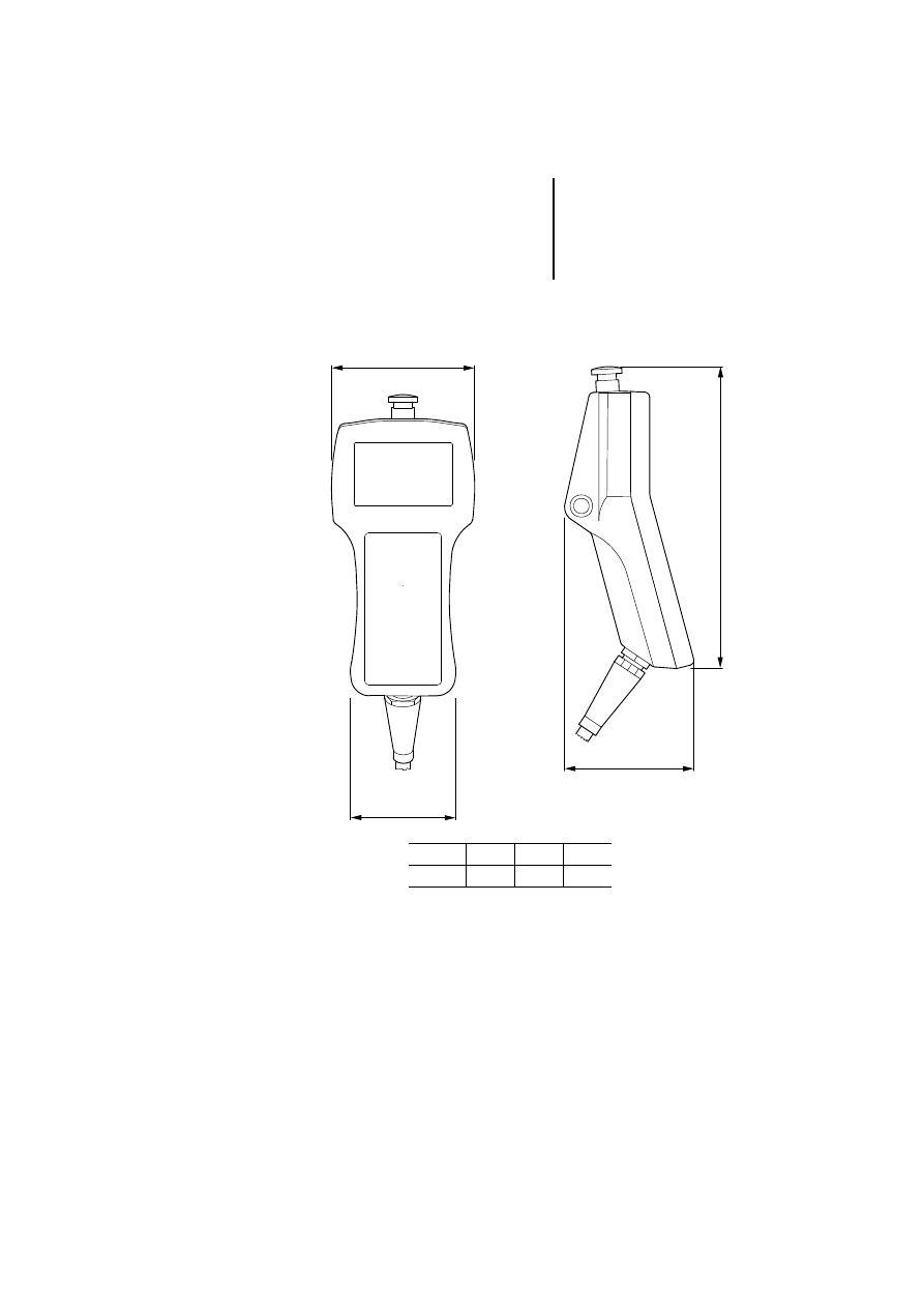
MI4-140-KF1
a
b
c
d
a
b
c
d
116
86
102
239
Operation
54
12
/0
3
AWB
-C
2
7-
12
93
GB
Communication cables
Text operator panel (without PC/PRINTER PORT)
햲 Adapter, supplied as standard with ZB4-24A-KP1
cable.
햳 Other interface module can be connected in place of
the Suconet K interface module:
PROFIBUS-DP
ZB4-504-IF1/-IF2
Siemens MPI
ZB4-505-IF1/-IF2
DeviceNet
ZB4-506-IF1
CANopen
ZB4-507-IF1
For cable assignments of these interfaces, see section
“Engineering”. For an overview, see page 12.
RS 232/RS
485
PLC PORT
MI4
AUX PORT
햲 Sucom A
Suconet K
(ZB4-501-IF1)
Other
interface
modules
ZB4-
24A-KP1
ZB4-
2B3-KB1
ZB4-
2B7-KB1
ZB4-
2B3-KB2
ZB4-
231-KB1
ZB4-
233-KB2
햳
RS 232
RS 232
RS 232
RS 485
RS 485
RS 485
PC
PS416-CPU
PS4-150
PS4-200
PS4-300
PS416-CPU
PS4-150
PS4-200
PS4-300
PS416
XC100/
200/600
Non-
Moeller
devices
Communication cables
55
12
/0
3
AWB
-C
2
7-
12
93
GB
Text operator panel (with PC/PRINTER PORT)
Graphic/touch operator panel
햲 Other interface modules can be connected in place of
the Suconet K module:
PROFIBUS-DP
ZB4-504-IF1
Siemens MPI
ZB4-505-IF1/-IF2
DeviceNet
ZB4-506-IF1
CANopen
ZB4-507-IF1
For cable assignments of these interfaces, see section
“Engineering”. For an overview, see page 12.
* The following units are supplied with a fitted Suconet-K
interface (ZB4-501-IF1):
MI4-101-KC1
MI4-101-KE1/MI4-111-KE1
MI4-131-KH1
MI4-151-KF1/MI4-451-KF1
MI4-151-TA1/MI4-451-TA1
MI4-161-TC1/MI4-471-TC1
RS 232
RS 232/RS 485
PC/PRINTER
PORT
MI4
PLC PORT
AUX PORT
Sucom A
Suconet K*
Other
interface
modules
ZB4-24A-
K
P1
ZB4-2B3-KB1
ZB4-2B7-KB1
ZB4-2B3-KB2
ZB4-231-K
B
1
ZB4-233-K
B
2
햲
RS 232
RS 232
RS 232
RS 485
RS 485
RS 485
PC
PS416-CPU
PS4-150
PS4-200
PS4-300
PS416-CPU
PS4-150
PS4-200
PS4-300
PS416
XC100/
200/600
Non-
Moeller
devices
Operation
56
12
/0
3
AWB
-C
2
7-
12
93
GB
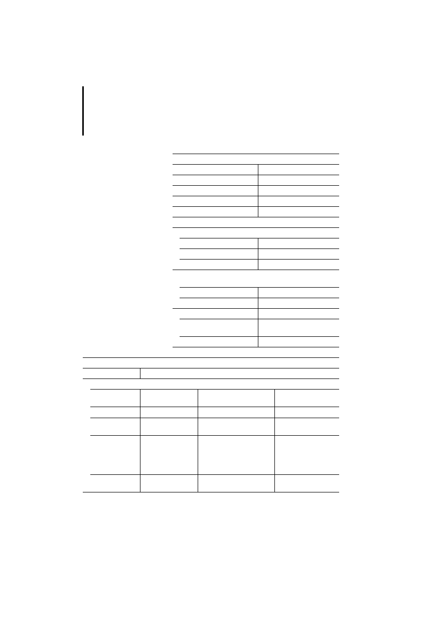
Technical data
General
Standards
EN 61 131-2, EN 50 178
Shock resistance
15 g/11 ms
Vibration resistance
Constant 1g, f = 0 to 150 Hz
Cable cross-section
0.22 to 1.5 mm
2
EMC
See below
Ports
PC/PRINTER PORT
Type
RS 232
Transmission rate
600 to 38400 kbit/s
Plug type
15-pin, Sub-D socket
PLC PORT
PLC/PC PORT
Type
RS 232, RS 485
Plug type
15-pin, Sub-D plug
AUX PORT
Type
Depending on connected
interface module
Plug type
9-pin, Sub-D socket
General electromagnetic compatibility (EMC) data for automation devices
Emitted interference
EN 55 011/22 Class A
Interference immunity
ESD
EN 61 000-4-2
Contact discharge
Air discharge
4 kV
8 kV
RFI
EN 61 000-4-3
AM/PM
10 V/m
Burst
EN 61 000-4-4
Network/digital I/O
Analog I/O, field bus
2 kV
1 kV
Surge
EN 61 000-4-5
Digital O/O, asymmetrical
Network DC, asymmetrical
Network DC, symmetrical
Network AC, asymmetrical
Network AC, symmetrical
0.5 kV
1 kV
0.5 kV
2 kV
1 kV
Line-conducted
interference
EN 61 000-4-6
AM
10 V
T
echnical data
57
12/03 AWB-C27-1293GB
Text operator panel (not graphics-capable)
MI4-...
100-KC1
101-KC1
100-KE1
101-KE1
110-KE1
111-KE1
130-KH1
131-KH1
Display
Monochrome
LCD
Monochrome
LCD
Monochrome
LCD
Monochrome
LCD
Monochrome
LCD
Monochrome
LCD
Monochrome
LCD
Monochrome
LCD
Backlighting
LED
LED
LED
LED
LED
LED
LED
LED
Contrast adjustment
Software
Software
Software
Software
Software
Software
Software
Software
Graphics capability
No
No
No
No
No
No
No
No
Number of colours/
grey levels
–
–
–
–
–
–
–
–
Rows x characters
2 x 20
2 x 20
2 x 20
2 x 20
4 x 20
4 x 20
4 x 40
4 x 40
Display dimensions in
mm
80 x 16
80 x16
72 x 16
72 x 16
72 x 24
72 x 24
138 x 28
138 x 28
Scaleable font
No
No
No
No
No
No
No
No
User-definable
characters
8
8
8
8
8
8
8
8
Keys
Numeric keypad
–
–
Yes
Yes
Yes
Yes
Yes
Yes
F-keys (with LED),
labelling facility
4
4
9
9
9
9
16
16
Total no. of user-
programmable keys
10
10
19
19
19
19
35
35
User LEDs
4
4
9
9
9
9
16
16
Touch function
–
–
–
–
–
–
–
–
Operation
58
12/03 AWB-C27-1293GB
Memory
Flash project memory
128 kb (32 kb reserved for protocol)
Recipe memory
–
–
–
–
16 kb
16 kb
16 kb
16 kb
Project memory
expansion
–
–
–
–
512 kb
512 kb
512 kb
512 kb
Special features
Battery
–
–
–
–
Yes
Yes
Yes
Yes
Number of alarm
messages
256
256
256
256
1024
1024
1024
1024
Number of history
memory messages
–
–
–
–
256
256
256
256
Number of variables per
page
Unlimited
Unlimited
Unlimited
Unlimited
Unlimited
Unlimited
Unlimited
Unlimited
Password
Yes
Yes
Yes
Yes
Yes
Yes
Yes
Yes
Real-time clock
Yes, without battery back-up
Yes
Yes
Yes
Yes
Screen saver
–
–
–
–
–
–
–
–
Buzzer
–
–
–
–
–
–
–
–
Printer port
–
–
–
–
Yes
Yes
Yes
Yes
MI4-...
100-KC1
101-KC1
100-KE1
101-KE1
110-KE1
111-KE1
130-KH1
131-KH1
T
echnical data
59
12/03 AWB-C27-1293GB
Ports
RS 232C/RS 485 combination port for:
- Sucom A
Yes
Yes
Yes
Yes
Yes
Yes
Yes
Yes
- Configuration
Yes
Yes
–
–
Yes
Yes
–
–
RS232C port for:
- Configuration
–
–
Yes
Yes
Yes
Yes
- Printer connection
–
–
–
–
Yes
Yes
Yes
Yes
1 fieldbus interface, plug-in modules for:
- Suconet K
Yes
Yes, plugged
in
Yes
Yes, plugged
in
Yes
Yes, plugged
in
Yes Yes,
plugged
in
- PROFIBUS-DP
Yes
Yes
Yes
Yes
Yes
Yes
Yes
Yes
- Siemens MPI
Yes
Yes
Yes
Yes
Yes
Yes
Yes
Yes
- DeviceNet
Yes
Yes
Yes
Yes
Yes
Yes
Yes
Yes
- CANopen
Yes
Yes
Yes
Yes
Yes
Yes
Yes
Yes
Power supply
Rated voltage
24 V DC
24 V DC
24 V DC
24 V DC
24 V DC
24 V DC
24 V DC
24 V DC
Permissible range (V DC) 20.4 to 28.8 20.4 to 28.8
20.4 to 28.8
20.4 to 28.8
20.4 to 28.8
20.4 to 28.8
20.4 to 28.8
20.4 to 28.8
Reverse polarity
protection
Yes
Yes
Yes
Yes
Yes
Yes
Yes
Yes
Rated current
250 mA
250 mA
250 mA
250 mA
250 mA
250 mA
400 mA
400 mA
Fuses
Electronic
Electronic
2 A
replaceable
2 A
replaceable
2 A
replaceable
2 A
replaceable
2 A
replaceable
2 A
replaceable
MI4-...
100-KC1
101-KC1
100-KE1
101-KE1
110-KE1
111-KE1
130-KH1
131-KH1

Operation
60
12/03 AWB-C27-1293GB
General
Weight in kg
0.8
0.8
1
1
1
1
1.9
1.9
Degree of protection
(front) IP65
Yes
Yes
Yes
Yes
Yes
Yes
Yes
Yes
Ambient temperature in
°C
0 – 50
0 – 50
0 – 50
0 – 50
0 – 50
0 – 50
0 – 50
0 – 50
Storage temperature in
°C
–20 to +70
–20 to +70
–20 to +70
–20 to +70
–20 to +70
–20 to +70
–20 to +70
–20 to +70
Keyboard lifespan
(keystrokes)
> 3 million
> 3 million
> 3 million
> 3 million
> 3 million
> 3 million
> 3 million
> 3 million
Touchscreen lifespan
(operations)
–
–
–
–
–
–
–
–
Cable cross-section in
mm²
1 x 1.5
1 x 1.5
1 x 1.5
1 x 1.5
1 x 1.5
1 x 1.5
1 x 1.5
1 x 1.5
Connection type: Plug-in
screw terminal
Yes
Yes
Yes
Yes
Yes
Yes
Yes
Yes
Dimensions W x H x D in
mm
149 x 109 x
64
149 x 109 x
64
195 x 98 x
74
195 x 98 x
74
195 x 98 x 74 195 x 98 x 74 311 x 165 x
80
311 x 165 x
80
MI4-...
100-KC1
101-KC1
100-KE1
101-KE1
110-KE1
111-KE1
130-KH1
131-KH1
T
echnical data
61
12/03 AWB-C27-1293GB
Graphics-capable text operator panel
MI4-...
110-KC1
110-KD1
110-KG2
110-KG1
140-KF1
140-KI1
140-KJ1
Display
Monochrome
LCD
Monochrome
LCD
Monochrome
LCD
Monochrome
LCD
Monochrome
LCD
Monochrome
LCD
Monochrome
LCD
Backlighting
LED
LED
LED
LED
LED
LED
LED
Contrast adjustment
Software
Software
Software
Software
Software
Software
Software
Graphics capability
Yes
Yes
Yes
Yes
Yes
Yes
Yes
Number of colours/grey
levels
–
–
–
–
–
–
–
Rows x characters
4 x 20
4 x 20
4 x 20
4 x 20
8 x 20
8 x 40
8 x 40
Resolution in pixels
120 x 32
120 x 32
120 x 32
120 x 32
120 x 64
240 x 64
240 x 64
Display dimensions
70 x 21 mm
70 x 21 mm
70 x 21 mm
70 x 21 mm
66 x 33 mm
127 x 34 mm
127 x 34 mm
Scaleable font
Yes
Yes
Yes
Yes
Yes
Yes
Yes
User-definable
characters
256
256
256
256
256
256
256
Keys
Numeric keypad
–
Yes
Yes
Yes
Yes
Yes
Yes
F-keys (with LED),
labelling facility
4
9
12
12
9
23
23
Total number of user-
programmable keys
11
19
35
35
27
46
46
Electromechanical
keypads can be fitted
–
–
–
–
–
–
Yes
User LEDs
4
10
13
13
21
24
32
Touch function
–
–
–
–
–
–
–

Operation
62
12/03 AWB-C27-1293GB
Memory
Flash project memory
512 kb
512 kb
512 kb
512 kb
512 kb
512 kb
512 kb
Recipe memory
–
16 kb
–
16 kb
16 kb
16 kb
16 kb
Project memory
expansion
–
–
512 kb
512 kb
–
512 kb
512 kb
Special features
Battery
–
Yes
–
Yes
Yes
Yes
Yes
Number of alarm
messages
256
1024
256
1024
1024
1024
1024
Number of history
memory messages
–
256
–
256
256
256
256
Number of variables per
page
Unlimited
Unlimited
Unlimited
Unlimited
Unlimited
Unlimited
Unlimited
Password
Yes
Yes
Yes
Yes
Yes
Yes
Yes
Real-time clock
Yes, without
back-up
Yes
Yes, without
back-up
Yes
Yes
Yes
Yes
Screen saver
–
–
–
–
–
–
–
Buzzer
–
–
–
–
–
–
–
Printer port
–
–
–
Yes
Yes
Yes
Yes
MI4-...
110-KC1
110-KD1
110-KG2
110-KG1
140-KF1
140-KI1
140-KJ1
T
echnical data
63
12/03 AWB-C27-1293GB
Ports
RS232C/RS485 combination port for:
- Sucom A
Yes
Yes
Yes
Yes
Yes
Yes
Yes
- Configuration
Yes
Yes
Yes
–
–
–
–
RS232C port for:
- Configuration
–
–
–
Yes
Yes
Yes
Yes
- Printer connection
–
–
–
Yes
Yes
Yes
Yes
1 fieldbus interface, plug-in modules for:
- Suconet K
Yes
Yes
Yes
Yes
Yes
Yes
Yes
- PROFIBUS-DP
Yes
Yes
Yes
Yes
No
Yes
Yes
- Siemens MPI
Yes
Yes
Yes
Yes
Yes
Yes
Yes
- DeviceNet
Yes
Yes
Yes
Yes
No
Yes
Yes
- CANopen
Yes
Yes
Yes
Yes
No
Yes
Yes
Power supply
Rated voltage
24 V DC
24 V DC
24 V DC
24 V DC
24 V DC
24 V DC
24 V DC
Permissible range (V DC) 18 to 30
18 to 30
18 to 30
18 to 30
18 to 30
18 to 30
18 to 30
Reverse polarity
protection
Yes
Yes
Yes
Yes
Yes
Yes
Yes
Rated current
250 mA
250 mA
300 mA
300 mA
300 mA
400 mA
400 mA
Fuses
Electronic
Electronic
Electronic
Electronic
Electronic
Electronic
Electronic
MI4-...
110-KC1
110-KD1
110-KG2
110-KG1
140-KF1
140-KI1
140-KJ1

Operation
64
12/03 AWB-C27-1293GB
General
Weight in kg
1
1
1.1
1.1
1.5 incl. cable 2
2
Degree of protection
(front) IP65
Yes
ja
Yes
Yes
Yes
Yes
Yes
Ambient temperature in
°C
0 – 50
0 – 50
0 – 50
0 – 50
0 – 50
0 – 50
0 – 50
Storage temperature in
°C
–20 to +70
–20 bis +70
–20 to +70
–20 to +70
–20 to +70
–20 to +70
–20 to +70
Keyboard lifespan
(keystrokes)
> 3 million
> 3 Mio
> 3 million
> 3 million
> 3 million
> 3 million
> 3 million
Touchscreen lifespan
(operations)
–
–
–
–
–
–
–
Cable cross-section in
mm²
1 x 1.5
1 x 1,5
1 x 1.5
1 x 1.5
Open
cable end
1 x 1.5
1 x 1.5
Connection type, plug-in
screw terminal
Yes
ja
Yes
Yes
–
Yes
Yes
Dimensions in mm
149 x 109 x
60
149 x 109 x
58
141 x 176 x 76 141 x 176 x
76
116 x 239 x
102
220 x 176 x
71
275 x 220 x
77
MI4-...
110-KC1
110-KD1
110-KG2
110-KG1
140-KF1
140-KI1
140-KJ1
T
echnical data
65
12/03 AWB-C27-1293GB
Graphic operator panels
MI4-151-KF1
MI4-451-KF1
MI4-150-KI1
MI4-450-KI1
MI4-170-KH1
MI4-570-KH1
Display
Monochr. LCD
Colour LCD-STN
Monochr. LCD
Colour LCD-STN
Monochr. LCD
TFT
Backlighting
CCFL
CCFL
CCFL
CCFL
CCFL
CCFL
Contrast adjustment
Autom.
Autom.
Software
Software
Software
Software
Graphics capability
Yes
Yes
Yes
Yes
Yes
Yes
Number of colours/grey levels
–
16
–
16
–
256
Rows x characters
16 x 40
16 x 40
16 x 40
16 x 40
30 x 80
30 x 80
Resolution in pixels
320 x 240
320 x 240
320 x 240
320 x 240
640 x 480
640 x 480
Display dimensions in mm
121 x 91/5.6"
121 x 91/5.6"
121 x 91/5.6"
121 x 91/5.6"
212 x 159/10,4“
Scaleable font
Yes
Yes
Yes
Yes
Yes
Yes
User-definable characters
256
256
256
256
256
256
Keys
Numeric keypad
Yes
Yes
Yes
Yes
Yes
Yes
F-keys (with LED), labelling facility
10
10
33 (24 – 33 no LED)
23
23
Total number of user-programmable
keys
37
37
56
56
50
50
User LEDs
10
10
24
24
24
24
Touch function
–
–
–
–
–
–
Memory
Flash project memory
512 kb (64 kb reserved for protocol) 8 MB SSFDC card
8 MB SSFDC card
Recipe memory
32 kb
32 kb
32 kb
32 kb
32 kb
32 kb
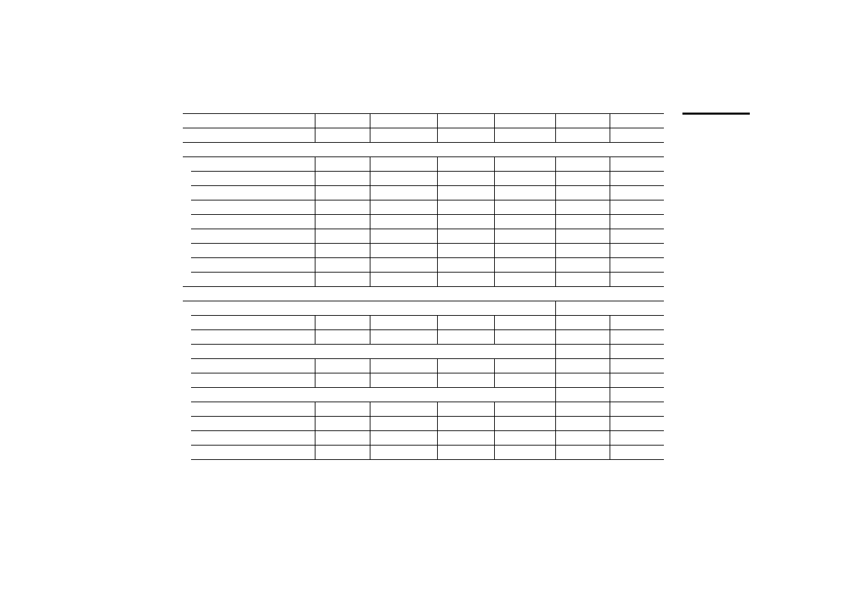
Operation
66
12/03 AWB-C27-1293GB
Project memory expansion
512 kb
512 kb
–
–
–
–
Special features
Battery
Yes
Yes
Yes
Yes
Yes
Yes
Number of alarm messages
1024
1024
1024
1024
1024
1024
Number of history memory messages 1024
1024
1024
1024
1024
1024
Number of variables per page
Unlimited
Unlimited
Unlimited
Unlimited
Unlimited
Unlimited
Password
Yes
Yes
Yes
Yes
Yes
Yes
Real-time clock
Yes
Yes
Yes
Yes
Yes
Yes
Screen saver
Yes
Yes
Yes
Yes
Yes
Yes
Buzzer
–
–
–
–
–
–
Printer port
Yes
Yes
Yes
Yes
Yes
Yes
Ports
RS232C/RS485 combination port for:
- Sucom A
Yes
Yes
Yes
Yes
Yes
Yes
- Configuration
–
–
–
–
–
–
RS232C port for:
- Configuration
Yes
Yes
Yes
Yes
Yes
Yes
- Printer connection
Yes
Yes
Yes
Yes
Yes
Yes
1 fieldbus interface, plug-in modules for:
- Suconet K
Plugged in
Plugged in
Yes
Yes
Yes
Yes
- PROFIBUS-DP
Yes
Yes
Yes
Yes
Yes
Yes
- Siemens MPI
Yes
Yes
Yes
Yes
Yes
Yes
- DeviceNet
Yes
Yes
Yes
Yes
Yes
Yes
MI4-151-KF1
MI4-451-KF1
MI4-150-KI1
MI4-450-KI1
MI4-170-KH1
MI4-570-KH1
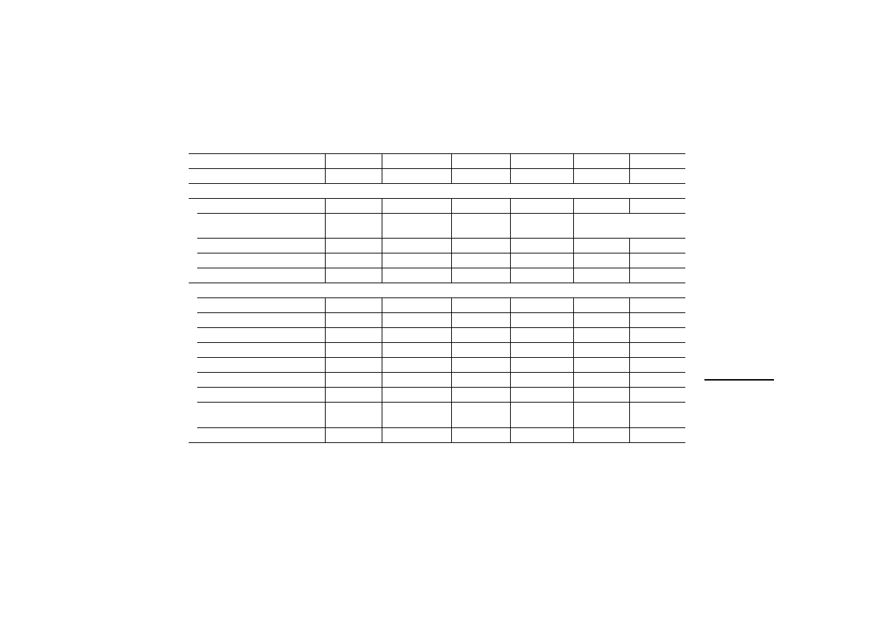
T
echnical data
67
12/03 AWB-C27-1293GB
- CANopen
Yes
Yes
Yes
Yes
Yes
Yes
Power supply
Rated voltage
24 V DC
24 V DC
24 V DC
24 V DC
24 V DC
24 V DC
Permissible range
20.4 to 28.8 V
DC
20.4 to 28.8 V DC
18 to 30 V DC
18 to 30 V DC
18 to 30 V DC
Reverse polarity protection
Yes
Yes
Yes
Yes
Yes
Yes
Rated current
500 mA
500 mA
600 mA
600 mA
700 mA
700 mA
Fuses
2 A replaceable 2 A replaceable
2 A replaceable 2 A replaceable
electronic
electronic
General
Weight in kg
1.4
1.4
1.9
1.9
2.5
2.5
Degree of protection (front) IP65
Yes
Yes
Yes
Yes
ja
ja
Ambient temperature in °C
0 – 50
0 – 50
0 – 50
0 – 50
0 – 50
0 – 50
Storage temperature in °C
–20 to +70
–20 to +70
–20 to +70
–20 to +70
–20 to +70
–20 to +70
Keyboard lifespan (keystrokes)
> 3 million
> 3 million
> 3 million
> 3 million
> 3 million
> 3 million
Touchscreen lifespan (operations)
–
–
–
–
–
–
Cable cross-section in mm²
1 x 1.5
1 x 1.5
1 x 1.5
1 x 1.5
1 x 1.5
1 x 1.5
Connection type
(plug-in screw terminal)
Yes
Yes
Yes
Yes
Yes
Yes
Dimensions W x H x D in mm
216 x 168 x 74 216 x 168 x 74
275 x 220 x 80 275 x 220 x 80
311 x 276 x 80 311 x 276 x 80
MI4-151-KF1
MI4-451-KF1
MI4-150-KI1
MI4-450-KI1
MI4-170-KH1
MI4-570-KH1
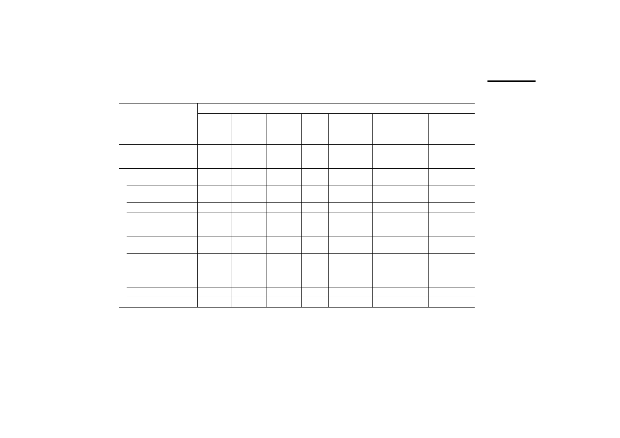
Operation
68
12/03 AWB-C27-1293GB
Touch operator panels
MI4-...
151-TA1*
451-TA1**
161-TC1
471-TC1
130-TA1
140-TA1*
150-TA1*
450-TA1**
550-TA1***
160-TA1*
470-TA1**
570-TA1***
580-TA1*
590-TA1**
Display
Monochr.*
colour STN**
Monochrome colour TFT
Monochr.
Monochr. *
colour STN**
colour TFT***
Monochr.*
colour STN**
colour TFT***
colour TFT
Backlighting
CCFL
CCFL
CCFL
LED
LED*
CCFL**
,
***
CCFL
CCFL
Contrast adjustment
autom.
Software
Software
Software
Software*
,
**
–***
Software*
,
**
–***
–
Graphics capability
Yes
Yes
Yes
Yes
Yes
Yes
Yes
Number of colours/grey levels –*
16**
256
256
–
–*
16**
256***
–*
256**
,
***
256
Rows x characters
16 x 40
25 x 80
30 x 80
16 x 40
16 x 40
30 x 80
40 x 100*
48 x 128**
Resolution in pixels
320 x 240
640 x 400
640 x 480
320 x 240 320 x 240
640 x 480
800 x 600*
1024 x 768**
Display dimensions in mm
121 x 91
5.6“
194 x 121
9.6"
212 x 159
10.4"
77 x 58
3.8“
121 x 91
5.6“
196 x 147.6/9.6“ *
218 x 159/10.4“ **
,
***
246 x 184/12.1“ *
304 x 228/15“ **
Scaleable font
Yes
Yes
Yes
Yes
Yes
Yes
Yes
User-definable characters
256
256
256
256
256
256
256
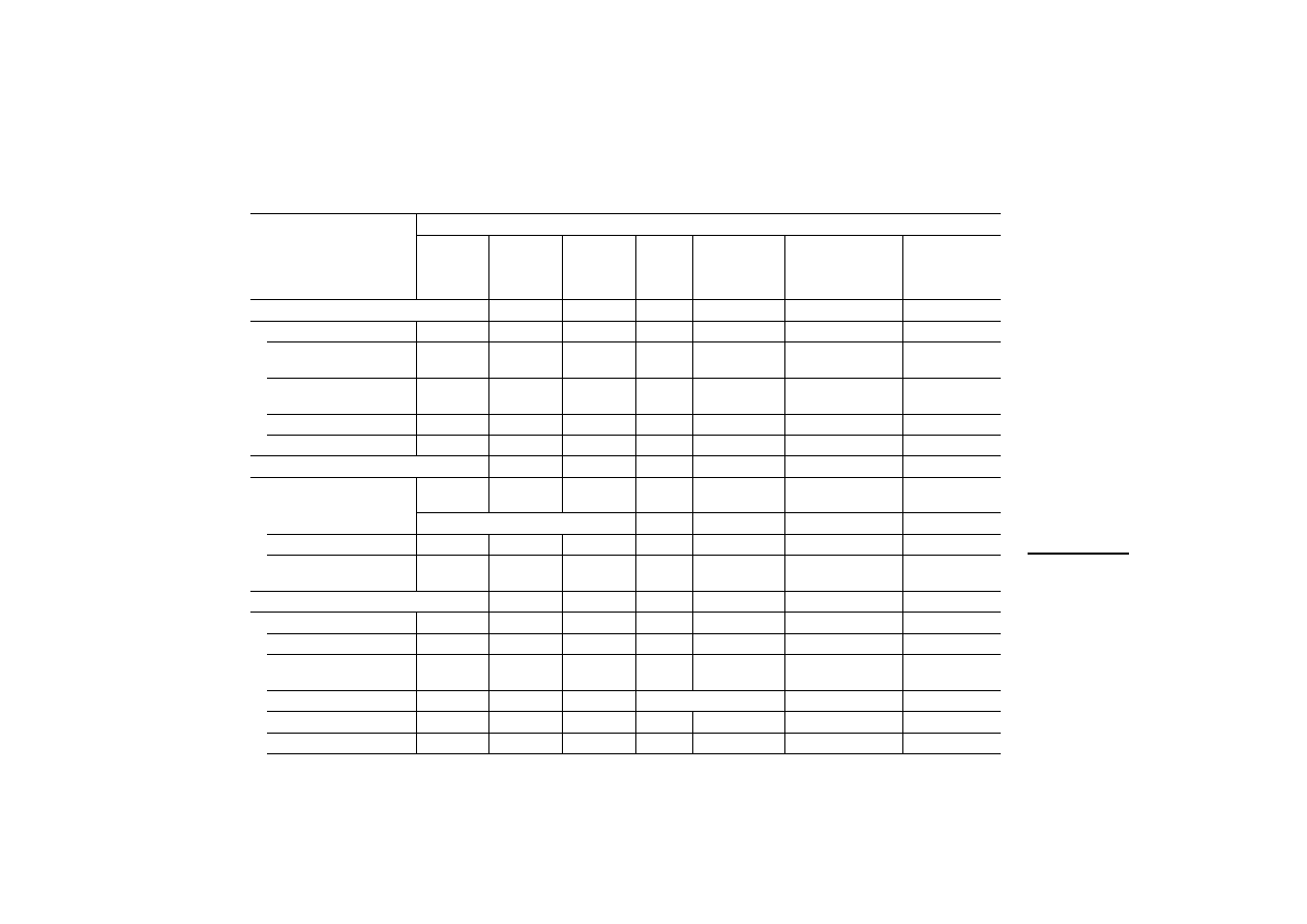
T
echnical data
69
12/03 AWB-C27-1293GB
Keys
Numeric keypad
–
–
–
–
–
–
–
F-keys (with LED), labelling
facility
–
2
2
–
–
–
–
Total no. of user-
programmable keys
–
9
9
–
–
–
–
User LEDs
–
3
3
–
–
–
–
Touch function
Resistive
Resistive
Resistive
Resistive
Resistive
Resistive
Resistive
Memory
Flash project memory
512 kb
512 kb
8 MB SSFDC
Karte
512 kb
8 MB SSFDC
Karte
8 MB SSFDC Karte
8 MB SSFDC Karte
64 kb reserved for protocol
Recipe memory
32 kb
32 kb
32 kb
32 kb
32 kb
32 kb
32 kb
Project memory
expansion
1)
512 kb
512 kb
512 kb
–
–
–
–
Special features
Battery
2)
Yes Yes Yes
Yes
Yes Yes Yes
Number of alarm messages
1024
1024
1024
1024
1024
1024
1024
Number of history memory
messages
1024
1024
1024
256
1024
1024
1024
Number of variables per page
unlimited
unlimited
unlimited
unlimited
unlimited
unlimited
Password
Yes
Yes
Yes
Yes
Yes
Yes
Yes
Real-time clock
Yes
Yes
Yes
Yes
Yes
Yes
Yes
MI4-...
151-TA1*
451-TA1**
161-TC1
471-TC1
130-TA1
140-TA1*
150-TA1*
450-TA1**
550-TA1***
160-TA1*
470-TA1**
570-TA1***
580-TA1*
590-TA1**

Operation
70
12/03 AWB-C27-1293GB
Screen saver
Yes
Yes
Yes
Yes
Yes
Yes
Yes
Buzzer
Yes
Yes
Yes
–
Yes
Yes
Yes
Printer port
Yes
Yes
Yes
–
Yes
Yes
Yes
Ports
RS232C/RS485 combination
port for:
- Sucom A
Yes
Yes
Yes
Yes
Yes
Yes
Yes
- Configuration
–
–
–
Yes
–
–
–
RS232C port for:
- Configuration
Yes
Yes
Yes
–
Yes
Yes
Yes
- Printer connection
Yes
Yes
Yes
–
Yes
Yes
Yes
1 fieldbus interface, plug-in
modules for:
- Suconet K
Plugged in
Plugged in
Plugged in
Yes
Yes
Yes
Yes
-PROFIBUS-DP
Yes
Yes
Yes
Yes
Yes
Yes
Yes
- Siemens MPI
Yes
Yes
Yes
Yes
Yes
Yes
Yes
- DeviceNet
Yes
Yes
Yes
Yes
Yes
Yes
Yes
- CANopen
Yes
Yes
Yes
Yes
Yes
Yes
Yes
Power supply
Rated voltage
24 V DC
24 V DC
24 V DC
24 V DC
24 V DC
24 V DC
24 V DC
Permissible range (V DC)
20.4 to 28.8 20.4 to 28.8 20.4 to 28.8 18 to 30
18 to 30
18 to 30
18 to 30
MI4-...
151-TA1*
451-TA1**
161-TC1
471-TC1
130-TA1
140-TA1*
150-TA1*
450-TA1**
550-TA1***
160-TA1*
470-TA1**
570-TA1***
580-TA1*
590-TA1**
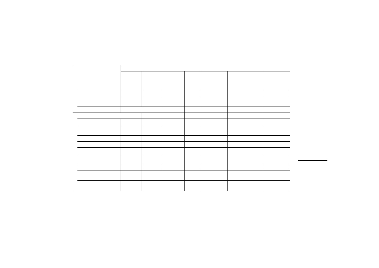
T
echnical data
71
12/03 AWB-C27-1293GB
1
Upgradeable with ZB4-512-SF1 memory module
2
3 V lithium, non-rechargeable, lifespan about 1 year, replaceable, replacement item ZB4-280-BT1
3
Bei MI4-140-TA1: T = 79 mm
Reverse polarity protection
Yes
Yes
Yes
Yes
Yes
Yes
Yes
Rated current
500
600
1000
400
600
600*
700**
,
***
800*
1200**
Fuses
2 A replaceable
Electronic
Electronic
Electronic
General
Weight in kg
1.4
2.7
2.7
1
1.4
2.25
2.85*, 3.85**
Degree of protection (front)
IP65
Yes
Yes
Yes
Yes
Yes
Yes
Yes
Ambient temperature
0 – 50 °C
0 – 50 °C
0 – 50 °C
0 – 50 °C 0 – 45 °C
0 – 45 °C
0 – 45 °C
Storage temperature in °C
–20 to +70
–20 to +70
–20 to +70
–20 to +70
–20 to +70
–20 to +70
Keyboard lifespan (keystrokes) –
–
–
–
–
–
–
Touchscreen lifespan
(operations)
> 1 million
> 1 million
> 1 million
> 3
million
> 3 million
> 3 million
> 3 million
Cable cross-section in mm²
1 x 1.5
1 x 1.5
1 x 1.5
1 x 1.5
1 x 1.5
1 x 1.5
1 x 1.5
Connection type (plug-in
screw terminal)
Yes
Yes
Yes
Yes
Yes
Yes
Yes
Dimensions W x H x D in mm
216 x 168 x
74
311 x 220 x
80
311 x 220 x
80
149 x 109
x 61
187 x 147 x 96
3)
287 x 232 x 96
337 x 267 x 96*
392 x 307 x 106**
MI4-...
151-TA1*
451-TA1**
161-TC1
471-TC1
130-TA1
140-TA1*
150-TA1*
450-TA1**
550-TA1***
160-TA1*
470-TA1**
570-TA1***
580-TA1*
590-TA1**
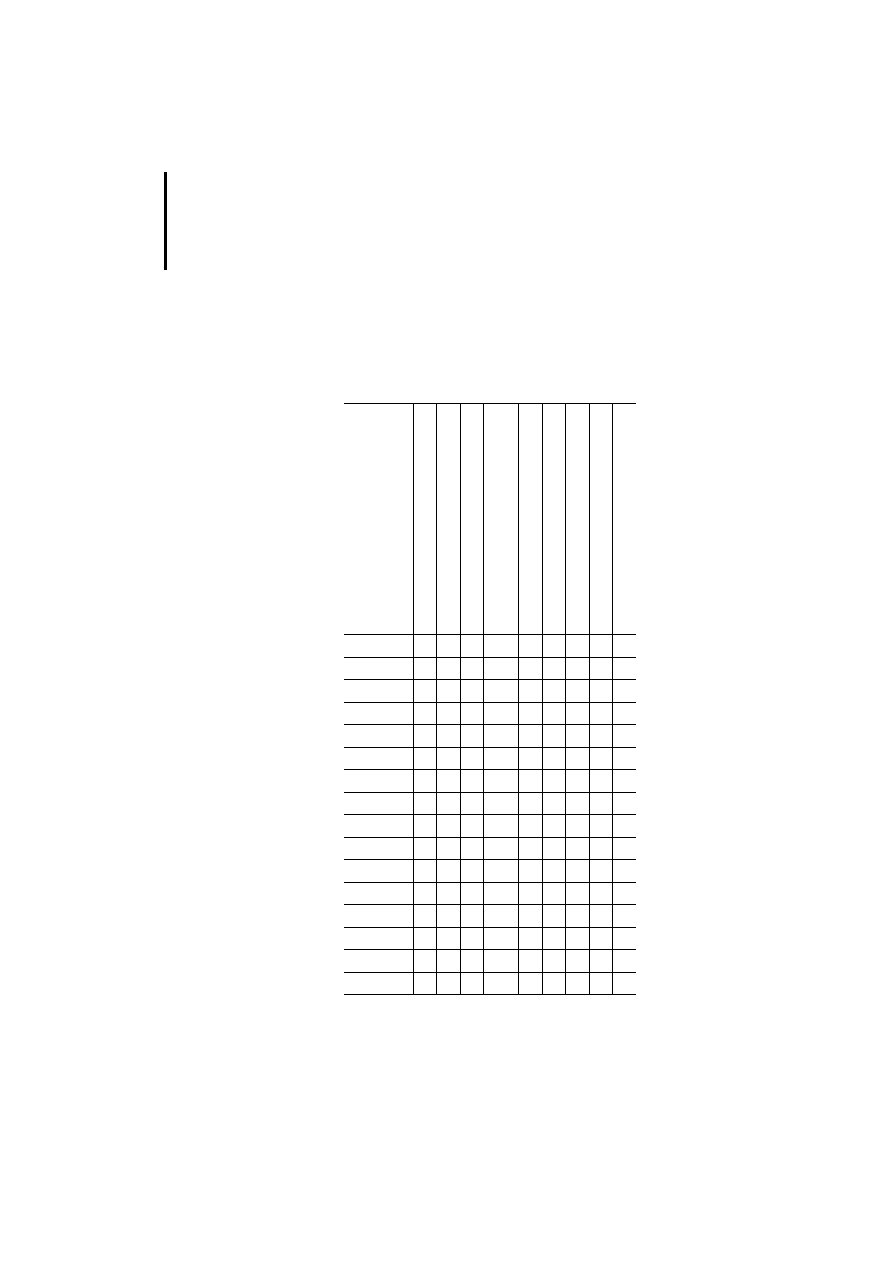
Operation
72
12
/0
3
AWB
-C
2
7-
12
93
GB
New features
All the new features available in MI4 models from
firmware version 4.40 and 4.50, are listed in the
following table.
Device firm ware
Tr
e
nd disp
lay
s
an
d pointe
r-
typ
e
instrumen
ts
P
o
p-up ke
ypads
Va
ri
a
b
le
s
Min./Ma
x
. v
a
riable s
e
tpoint v
a
lues
Exp
a
n
d
ed fon
t support
Re
cipe
back-up
SSFDC memor
y
card
Automatic f
ir
m
ware u
pgrade
Pixel and
vec
tor grap
hics
1)
MI4-100-KC1
32
j
j
MI4-101-KC1
32
j
j
MI4-110-KC1
32
j
j
MI4-110-KD1 52
j
j
MI4-100-KE1
32
j
j
MI4-101-KE1
32
j
j
MI4-110-KE1
32
j
j
MI4-111-KE1
32
j
j
MI4-110-KG1
32
j
j
MI4-110-KG2
32
j
j
MI4-130-KH1
32
j
j
MI4-131-KH1
32
j
j
MI4-140-KI1
32
j
j
MI4-140-KJ1
32
j
j
MI4-140-KF1
32
j
j
MI4-151-KF1
33
j
j
Technical data
73
12
/0
3
AWB
-C
2
7-
12
93
GB
1) from firm ware 4.50
MI4-151-TA1
33
j
j
MI4-161-TC1
33
j
j
MI4-451-KF1
37
j
j
MI4-451-TA1
37
j
j
MI4-150-KI1
38
j
j
j
MI4-450-KI1
38
j
j
j
MI4-170-KH1
58
j j j
j
j j j
MI4-570-KH1
58
j j j
j
j j j
MI4-471-TC1
38
j
j
j
j
MI4-130-TA1
53
j
j
j
MI4-140-TA1
38
j
j
j
j
MI4-450-TA1
38
j
j
j
j
MI4-150-TA1
38
j
j
j
j
MI4-550-TA1
58
j j j
j
j j j
MI4-570-TA1
58
j j j
j
j j j
MI4-470-TA1
58
j j j
j
j j j
MI4-160-TA1
58
j j j
j
j j j
MI4-580-TA1
58
j j j
j
j j j
MI4-590-TA1
58
j j j
j
j j j
Device firm war
e
Tr
e
nd displays
an
d pointe
r-
typ
e
instrumen
ts
P
o
p-up ke
ypads
Va
ri
a
b
le
s
Min./Max. v
a
riable setpoint v
a
lues
Exp
a
n
d
ed fon
t support
Re
cipe
back-up
SSFDC memor
y
card
Automatic firmware up
grade
P
ixe
l an
d v
e
ct
o
r gr
ap
hic
s
1)

74
12
/0
3
AWB
-C
2
7-
12
93
GB

75
12
/0
3
AWB
-C
2
7-
12
93
GB
Index
A
Ambient conditions ........................................................ 37
AUX PORT
Function ........................................................................ 7
Terminal assignment .......................... 14, 16, 17, 18, 19
B
Baud rate ....................................................................... 38
Bus termination with Suconet K .................................... 15
C
Cleaning ......................................................................... 37
Communication cables, overview .................................. 54
CONFIG ......................................................................... 40
Configuration ................................................................. 38
Connection diagram ........................................................ 9
Connections ..................................................................... 9
D
Data connections, MI4 ................................................... 12
Data interface, MI4 hand-held ....................................... 23
Data transfer rate ........................................................... 38
Date input mode ............................................................ 44
Delivery state, MI4 hand-held ........................................ 24
Device dimensions ................................................... 51, 52
Dimensions .................................................................... 51
DL ................................................................................... 48
Documentation, MI4 ........................................................ 3
Drilling dimensions ......................................................... 52
E
Earthing
Electromagnetic compatibility ....................................... 56
Engineering ...................................................................... 9

Index
76
12
/0
3
AWB
-C
2
7-
12
93
GB
F
Features ............................................................................ 6
Fitting dimensions .......................................................... 51
FLT ................................................................................. 48
Function keys, additional
MI 4-151-KF1, MI 4-451-KF1 ..................................... 46
MI 4-161-TC1, MI 4-471-TC1 ..................................... 47
G
Grounding ......................................................................... 9
I
Insert labels .................................................................... 35
Installation
Interface module ......................................................... 30
MI4 .............................................................................. 27
MI4 (hand-held) ........................................................... 29
Installing the interface module ....................................... 30
K
Key assignment
In alarm mode (ALARMS) ........................................... 43
In configuration mode ................................................. 40
In data entry mode ...................................................... 43
In direct access mode (ACCESS) ............................... 45
In events mode (EVENTS) ........................................... 44
In page mode .............................................................. 41
In page selection mode, direct ................................... 45
In password input mode ............................................. 44
In the Command menu ............................................... 41
In the System menu .................................................... 42
In time input mode ...................................................... 44
Key functions .................................................................. 39
L
LEDs ............................................................................... 48
Lifespan, battery ............................................................. 32
M
Maintaining ..................................................................... 37
O
Operation ........................................................................ 37

Index
77
12
/0
3
AWB
-C
2
7-
12
93
GB
P
Panel cutout ................................................................... 52
Panel overview ................................................................. 5
PASSWORD ................................................................... 44
PC, connecting .............................................................. 20
PC/PRINTER PORT
Function ........................................................................ 7
Terminal assignment .................................................. 21
PLC connection
CANopen .................................................................... 19
PROFIBUS-DP ........................................................... 16
Siemens MPI .............................................................. 17
Sucom A ..................................................................... 13
Suconet K ................................................................... 14
PLC PORT
Function ........................................................................ 7
Terminal assignment ............................................ 13, 22
Power supply ................................................................... 9
Printer, connecting ......................................................... 20
R
Replacing the battery ..................................................... 32
Resistive touch technology .............................................. 5
S
Suconet K module, connecting ..................................... 14
SYSTEM ......................................................................... 42
T
Technical data ................................................................ 56
Terminal assignment
Adapter extensions of MI4 hand-held ........................ 23
AUX PORT .......................................... 14, 16, 17, 18, 19
PC/PRINTER PORT .................................................... 21
PLC PORT ............................................................ 13, 22
TIME ............................................................................... 44
Touch technology, resistive ............................................. 5
Transfer rate ................................................................... 38
Document Outline
- Title
- Safety Instructions
- About This Manual
- 1 Display Units And Operator Panels
- 2 Engineering
- 3 Installation
- 4 Operation
- Appendix
- Index
Wyszukiwarka
Podobne podstrony:
mFAQ 3 6 S7 200 i panele operatorskie
FAQ Panele operatorskie HMI i ich możliwości konfiguracji
Panele operatorskie
The uA741 Operational Amplifier[1]
operatory i funkcje matematyczne
operator maszyn lesnych 833[02] o1 03 n
mechanik operator pojazdow i maszyn rolniczych 723[03] z2 04 n
Kierowca operator wózków jezdniowych 833401
mechanik operator pojazdow i maszyn rolniczych 723[03] o1 05 u
OPERAT STABLE VERSION ugoda id Nieznany
operator urzadzen przemyslu szklarskiego 813[02] z2 07 n
4 Steyr Operation and Maintenance Manual 8th edition Feb 08
operator urzadzen przemyslu spozywczego 827[01] z2 02 u
mechanik operator pojazdow i maszyn rolniczych 723[03] z3 02 n
więcej podobnych podstron