
A comparative study on conventional and orbital
drilling of woven carbon fiber reinforced epoxy
laminates
A. Sadek
(1)
, M. Meshreki
(2)
, Z. Shi
(2)
and H. Attia
(1,2)*
(1)
Department of Mechanical Engineering, McGill University, Montreal, QC, Canada
(2)
Aerospace Manufacturing Technology Centre, Institute for Aerospace Research,
National Research Council Canada, Montreal, QC, Canada
*helmi.attia@nrc.ca / helmi.attia@mcgill.ca
Abstract: Drilling of Carbon Fiber Reinforced Polymers (CFRPs) is a challenging
process of major economic and safety concerns for the aerospace industry. This research
work presents an experimental investigation of the orbital drilling technique versus
conventional drilling of woven CFRP laminates. Moreover, the tribological aspect of
conventional drilling is investigated through studying the effect of the dry machining,
air cooling, and Minimum Quantity Lubrication (MQL) conditions on the quality of
produced holes. This paper studies the attributes of hole quality for a range of material
removal rates (MRR): 11.4 to 22.8 cm³/min, using a three flute solid carbide 9.53 mm
drilling tool for conventional drilling. Corresponding conditions were employed to
produce 9.53 mm diameter holes using a 6.35 mm four flute end-mill for Conventional
Orbital Drilling (COD). The preliminary results of Superabrasive Orbital Drilling
(SAOD) using superabrasive diamond-coated steel tools are also presented. MQL and
air cooling resulted in reduced cutting temperatures, compared to conventional dry
drilling. COD produced delamination-free holes with enhanced hole surface quality, in
addition to the pronounced reduction in cutting temperatures and thrust forces.
Key words: Conventional and orbital drilling, Carbon Fiber Reinforced Polymers
(CFRPs), Minimum Quantity Lubrication (MQL), Machining-induced defects.
INTRODUCTION
The continuous evolution of usage of polymer composites in the aerospace industry
attracts more research efforts on different post-processing techniques applied to polymer
composites. Various novel drilling techniques e.g. Conventional Orbital Drilling (COD)
and Superabrasive Orbital Drilling (SAOD) are being used by today‟s aerospace
manufacturers. However, not much is known about the effects of employing such
processes on the quality attributes of the produced part.
Delamination of Carbon Fiber Reinforced Polymer (CFRP) layers is one of the
most critical defects associated with drilling of composite laminates. Delamination
could take place at the hole entry and/or exit, or through the layers of the laminate
thickness. The amount of delamination is controlled by the process parameters and the
quality of the bonding between the layers of the material. The entry delamination
becomes dominant in the case of high speed drilling, while the exit delamination
remains the most common type to take place during intermediate and low drilling
speeds [Rawat et al., 2009].
COD and SAOD are two emerging orbital drilling techniques that have
demonstrated a potential for eliminating defects associated with drilling of CFRP
laminates [Lindqvist et al., 2001] [Persson et al., 1997]. Such potential stems from the
nature of these processes, which is based on eliminating the axial dwell of the drilling
tool over the uncut material thickness [Iyer et al., 2006]. This is achieved through
rotating a cutting tool of a smaller diameter about its own axis and simultaneously about
the axis of the desired cylindrical hole, located at an offset distance from the tool axis.
The cutting tool used for COD is usually an end-mill or a cutting head with PCD inserts,
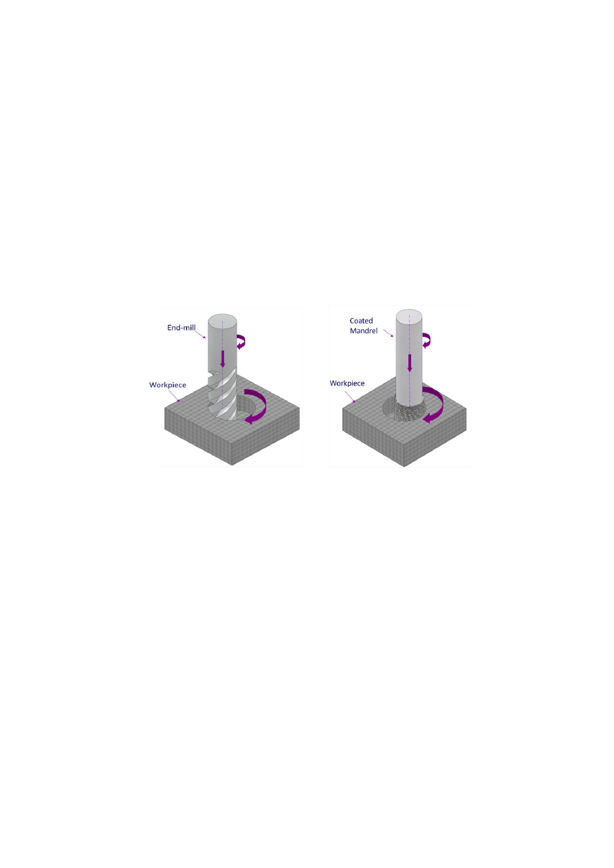
while a diamond coated mandrel is used for SAOD (Figure 1).
Figure 1 Description of tool types and motion in (a) COD, and (b) SAOD processes
The research work published in [Lindqvist et al., 2001] showed the results of using
COD to produce holes in sandwich constructions with aluminum and carbon
honeycomb core for aerospace applications. This process produced delamination-free
holes with allowable geometric accuracy. The tool experienced, however, considerable
chipping on the main cutting edge, due to the lack of tool dynamic stability.
Using fluted diamond-coated abrasive cutters for edge trimming of graphite/epoxy
laminates was investigated in [Colligan et al., 1999]. Delamination-free surfaces were
successfully produced. The surface quality and the cutting forces were reported to be
directly proportional to the grit size and the material removal rate (MRR), respectively.
The feed rate was reported to be of a minor effect on the surface quality. The results
reported in [Persson et al., 1997] compared the effect of producing holes via SAOD and
other conventional drilling processes on the behavior of the drilled CFRP laminates
under fatigue loading. A diamond coated mandrel rotating at a rotational speed of
25,000 rpm and an orbital speed of 125 rpm were employed. An enhanced static and
fatigue behaviors were reported for plates with holes produced by SAOD compared to
the behavior of plates with holes produced by conventional drilling.
(a)
(b)
The effect of air cooling and Minimum Quantity Lubrication (MQL) on the
produced surface finish, tool wear, cutting forces, and torques in drilling of Aluminum
was investigated in [Tasdelen et al, 2008]. However, no such study has been carried out
for drilling of CFRPs up to the present.
The objective of this research work is to conduct a comparative study between
SAOD, COD, and conventional drilling under dry, air cooled, and MQL conditions.
Such comparative study aims at ranking these processes, in terms of their capabilities
and limitations.
EXPERIMENTAL SET-UP
All the drilling tests were performed on a 5-axis Makino A88 machining centre, having
a 50 kW spindle, maximum spindle speed of 18,000 rpm and maximum feed rate of 50
m/min. The COD and SAOD tests were conducted under dry conditions. Conventional
drilling tests were conducted under dry, air cooled, and MQL conditions. The MQL
tests were performed using Vogel LubriLean Vario system connected through the
spindle. The aerosol was supplied through the coolant-through-holes of the tool. Air
pressure of 0.6 MPa and oil lubricant flow of 9 ml/hr were used for MQL drilling tests.
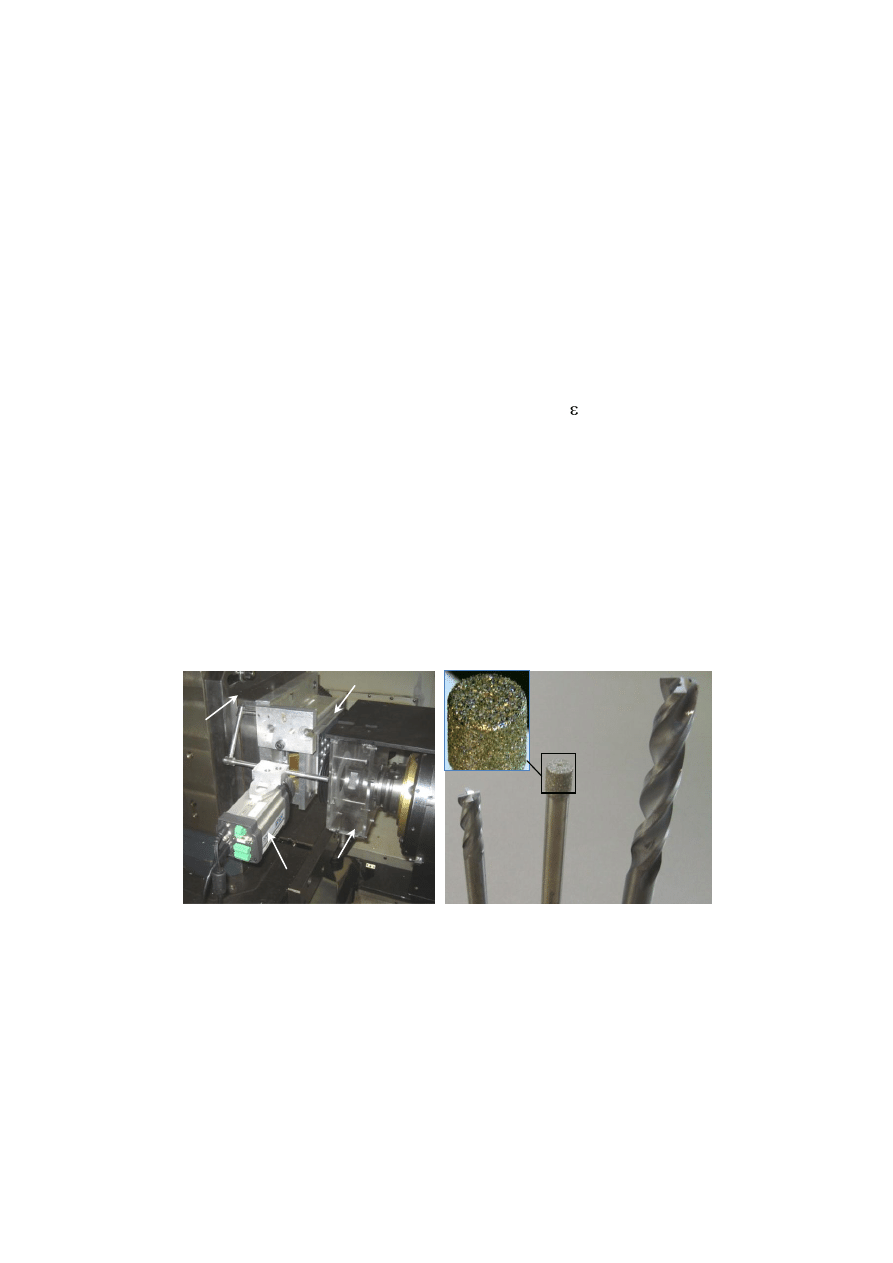
Figure 2(a) shows the experimental set-up used for the drilling experiments. Fixture (1)
was used to hold the CFRP laminates. The fine chips were evacuated using a special
vacuum arrangement (2). The cutting forces were recorded using a 3-component
dynamometer (3), Kistler 9255B, and 5070A Kistler charge amplifier. Cutting
temperatures were measured using a FLIR ThermoVision A20M Infrared camera (4) at
the hole exits.
Figure 2; (a) Experimental set-up, (b) Four flute end-mill, diamond coated steel
mandrel and three flute drill bit used for drilling of woven CFRP laminates
The test material used was a quasi-isotropic laminate comprising 35 plies of 8-
harness satin woven graphite epoxy prepreg. The laminate was manufactured by
autoclave molding with a cure time of 60 min at 127 °C under 516.75 kPa autoclave
pressure to produce a final cured thickness of 6.35 ± 0.02 mm. For conventional
drilling, a three-flute 9.53 mm diameter drill with a 30° helix angle, 150° point angle, a
2
1
3
4
3
2
1
(a)
(b)
fluted length of 63 mm and an overall length of 100 mm was used. The COD tests were
performed using a four flute 6.35 mm end-mill with a fluted length of 19 mm and a total
length of 63 mm. The SAOD tests were performed using a (100 Grit) diamond coated
6.35 mm
steel mandrel tool, with a coating length of 6.35 mm and an overall length of
76 mm. Figure 2(b) shows the three types of tools.
Delamination at the entry and exit of holes were investigated using the Olympus
Model GZX 12 optical microscope. Hole circularity and hole size errors along the depth
of the hole were measured using a „„Mitutoyo-Mach 806‟‟ coordinate measuring
machine (CMM). Surface roughness measurements were done using a Form Talysurf
series 2 surface profilometer.
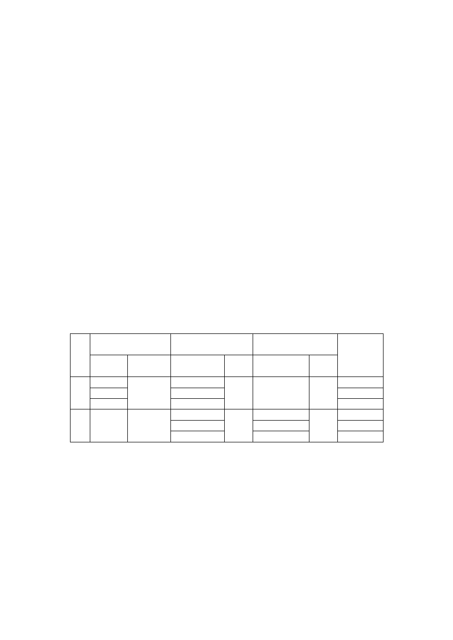
The test matrix for this research work is given in Table 1. Two sets of experiments
were conducted in order to perform this comparative study. The first group of tests
compared the conventional and COD tests that were performed at the same range of
rotational speeds; 6,000 to 12,000 rpm, and MRRs of 11.4 to 22.8 cm³/min. Such MRR
range was achieved by a single feed rate of 0.06 mm/rev for the conventional drilling
tests, versus a range of helical feed rates of 1,200 to 2,400 mm/min with a helical pitch
of 3 mm for the COD tests. The selection of this operating range was limited by the
capability of the machine tool to perform such an intricate helical motion at high helical
feeds. The second set of experiments was conducted to compare the performance of
COD and SAOD techniques at the same rotational speed of 16,000 rpm, with orbital
feed rates 600 to 1,200 mm/min and a helical pitch of 1 mm to produce a range of
MRRs 1.9 to 3.8 cm³/min.
Table 1 Test matrix for conventional, COD, and SAOD drilling
Set
Conventional (Dry,
Air, and MQL)
COD
SAOD
MRR
(cm³/min)
Speed
(rpm)
Feed rate
(mm/rev)
Orbital feed
(mm/min)
Pitch
(mm)
Orbital feed
(mm/min)
Pitch
(mm)
1
6,000
0.06
1,200
3
--
--
11.4
9,000
1,800
17.1
12,000
2,400
22.8
2
16,000
--
600
1
600
1
1.9
900
900
2.85
1,200
1,200
3.8
RESULTS AND DISCUSSION
In this section, the quality attributes of the holes produced using the SAOD, COD, and
conventional drilling under dry, air cooled, and MQL conditions are compared over the
ranges of MRR specified in Table 1. The MRR is a common parameter for conventional
and orbital drilling techniques that also has an indication on the productivity of the
process. For conventional drilling experiments, the MRR was increased by increasing
the rotational speed while the feed rate was fixed. For COD and SAOD the MRR was
increased by increasing the orbital feed while the rotational speed remained constant,
(Table 1).
1.1. Delamination
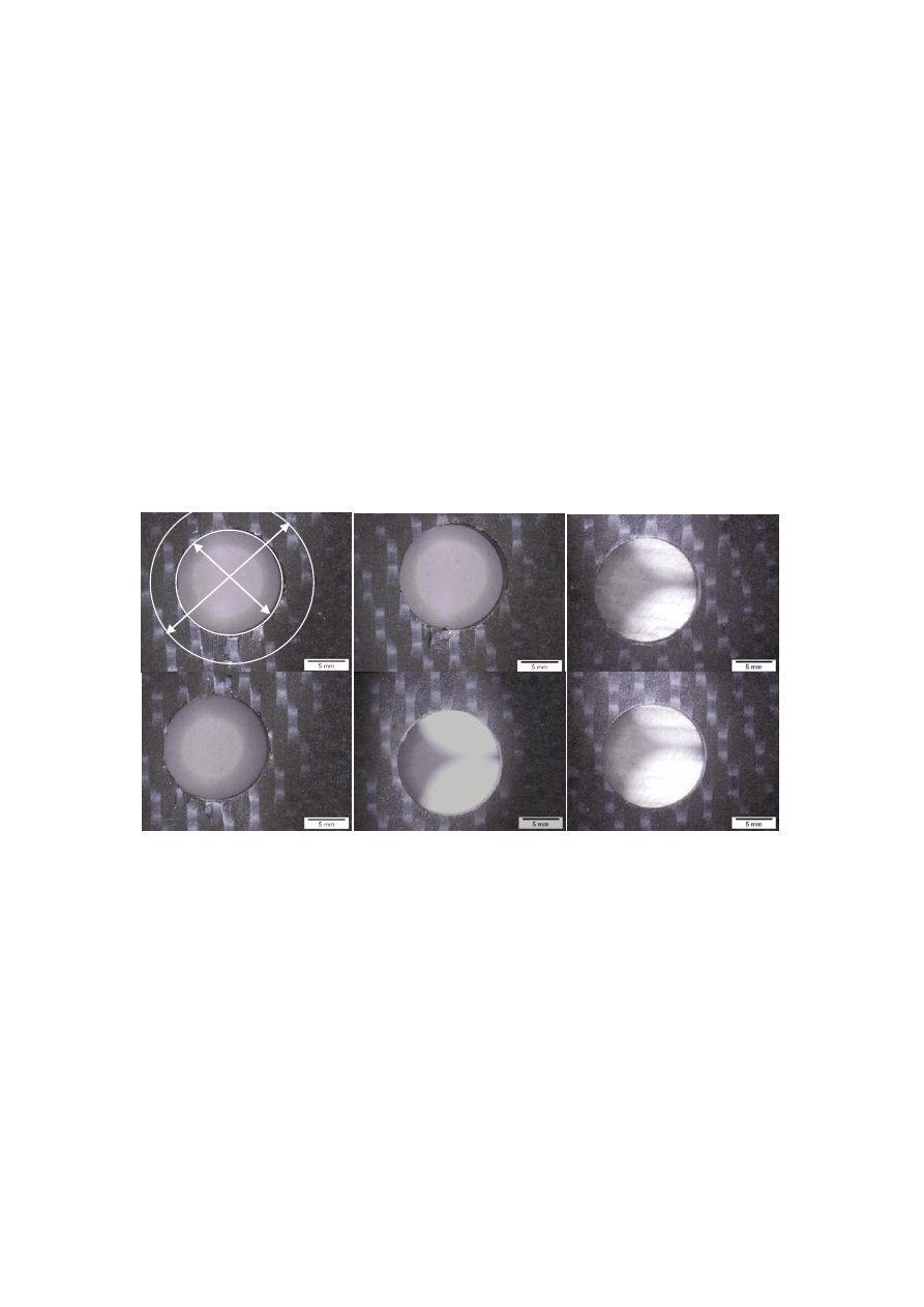
Hole entry and exit delamination were investigated. None of the holes produced by the
entire set of experiments has shown considerable entry delamination. The exit
delamination for holes produced at MRR 22.8 cm³/min using dry, air cooled, MQL
conventional drilling, and COD are shown in Figure 3 (a), (b), (c), and (d) respectively.
The delamination-free holes produced at MRR 3.8 cm³/min using COD and SAOD are
shown in Figure 3 (e), and (f), respectively.
The holes produced by conventional drilling showed considerable amounts of exit
delamination, while COD and SAOD resulted in delamination-free holes. The
delamination damage could be quantified by a delamination factor (ф
d
=D
max
/D
nominal
),
where “D
max
” is the maximum diameter that contains the observed delamination zone,
and “D
nominal
” is to the nominal hole diameter, as shown in Figure 3 (a).
Figure 3;Exit Delamination for holes produced at MRR 22.8 cm³/min using (a) Dry, (b)
Air cooled, (c) MQL conventional drilling, (d) COD at MRR 22.8 cm³/min, (e) COD at
MRR 3.8 cm³/min, and (f) SAOD at MRR 3.8 cm³/min
Figure 4 compares the exit delamination factors associated with dry, air cooled, and
MQL conventional drilling techniques. Two main trends could be concluded from
Figure 4. First, as the MRR is increased from 11.4 to 22.8 cm³/min the exit
delamination factor increases by an average of 7%, 23%, and 13% for dry, air, and
MQL, respectively. Second, the MQL resulted in about 6% and 8.5% reduction in the
delamination factor compared to the dry and air conditions, respectively.
The results shown in Figure 4 could be explained through investigating the drilling
thrust forces for each condition. Figure 5(a) and (b) show an increase in thrust forces in
all of the drilling techniques as the MRR increased, as a consequence of the higher feeds
(a)
(b)
(c)
(d)
(e)
(f)
D
max
D
hole
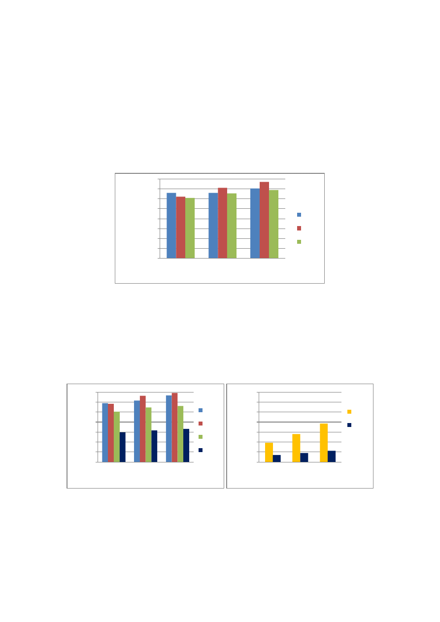
required to achieve higher MRRs. Figure 5(a) shows that the MQL resulted in a thrust
force average reduction of 17% and 20% compared to the dry and air cooled drilling,
respectively, which resulted in the relatively lower delamination factors exhibited by the
MQL drilling. The thrust forces associated with COD are 40% to 50% lower than those
obtained by conventional drilling under dry, air cooled, and MQL conditions. Such
percentage of reduction in thrust forces of the COD is attributed to the helical tool
motion that eliminates the stationary tool center [Persson et al., 1997], and is in
agreement with the percentage reported in [Langella et al., 2001].
Figure 4; Exit delamination factors of conventional drilling under
dry, air cooled, and MQL conditions
The thrust forces for the SAOD and COD at lower MRRs are compared in Figure
5(b). SAOD resulted in 60% to 75% increase in thrust forces compared to the COD.
This increase can be attributed to (i) the absence of the real oblique cutting condition in
the SAOD process where higher specific cutting forces are required due to the smaller
equivalent chip size, and (ii) the higher effect of frictional forces generated as a result of
the engagement of the abrasive particles with the epoxy matrix, as well as the particle‟s
shallow clearance [Ahmad et al., 2009][Colligan et al., 1999].
Figure 5; Drilling thrust forces for (a) COD and conventional drilling under
dry, air, and MQL conditions. (b) COD and SAOD at lower MRR levels
During the drilling process, the remaining thickness of material near the hole exit
starts to fail experiencing delamination above a certain threshold drilling thrust force
0.00
0.20
0.40
0.60
0.80
1.00
1.20
1.40
1.60
11.4
17.1
22.8
Exi
t
D
e
lam
in
ation
Fact
o
r
(ɸ
d
)
Material Removal Rate (cm³/min)
Dry
Air
MQL
0
50
100
150
200
250
300
350
11.4
17.1
22.8
Th
ru
st
Fo
rc
e
(
N
)
Material Removal Rate (cm³/min)
Dry
Air
MQL
COD
0
50
100
150
200
250
300
350
1.9
2.85
3.8
Th
ru
st
Fo
rc
e
(
N
)
Material Removal Rate (cm³/min)
SAOD
COD
(a)
(b)
level F
t,threshod
[Ho-Cheng et al., 1990]. The results in Figure 5(a) and (b) suggest that the
level of the drilling thrust force in the COD and SAOD did not exceed this threshold
value, since no delamination was associated with these techniques.
1.2. Drilling Temperature
Thermal damage during machining is a critical aspect that must be considered while
studying the impact of different process parameters on hole quality attributes. CFRPs
are sensitive to thermal damage that causes material deterioration and decomposition at
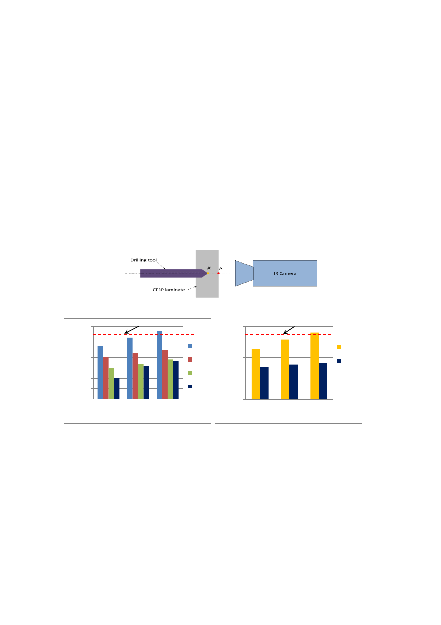
the machined surface and/or within the heat affected zones. Figure 6 shows a schematic
representation of the temperature measurement using the IR camera. The temperature is
monitored for the point of interest (point A), which is the intersection of the axis of the
hole to be drilled and the outermost layer on the exit side of the CFRP laminate. The
maximum temperature takes place when point (A‟) on the tool tip coincides with point
(A) at the instant of the exit penetration of the tool tip. The results shown in Figure 7(a)
and (b) represent the maximum recorded temperature for each drilling condition.
Figure 6; Schematic of temperature measurement using the IR camera
Figure 7; Maximum temperature at the tool exit for (a) COD and conventional drilling
under dry, air, and MQL conditions, and (b) COD and SAOD at lower MRR levels
Figure 7(a) shows the exit temperatures for COD and for conventional drilling
under dry, air cooled, and MQL conditions. In all of the involved techniques, the exit
temperature increased as the MRR increased. This is a result of the friction-induced
temperature rise associated with higher rotational speeds. Compared to conventional dry
drilling, the use of MQL and air cooling resulted in temperature reduction by 40% to
45% and 25% to 30%, respectively. COD resulted in a significant temperature reduction
of 45% to 60% compared to conventional dry drilling due to the intermittent cutting
nature of COD that creates a cyclic tool cooling effect during cutting.
0
50
100
150
200
250
300
350
11.4
17.1
22.8
Exi
t
Tem
p
e
ratu
re
(
°C)
Material Removal Rate (cm³/min)
Dry
Air
MQL
COD
0
50
100
150
200
250
300
350
1.9
2.85
3.8
Exi
t
Tem
p
e
ratu
re
(
°C)
Material Removal Rate (cm³/min)
SAOD
COD
(a)
(b)
Material decomposition temperature
Material decomposition temperature

Figure 7(b) compares the exit temperatures obtained in COD to SAOD at lower
MRR levels. COD resulted in temperature levels 40% to 45% lower than SAOD, which
involves higher specific cutting energies and consequently significant effect of friction-
induced temperature rise. Thermogravimetric Analysis (TGA) test was performed in
order to determine the decomposition temperature of the CFRP material being used. In
Figure 7(a) and (b), only the dry and SAOD processes at the highest MRR slightly
crossed the decomposition temperature limit.
1.3. Hole Surface Roughness
The arithmetical mean surface roughness „Ra‟ was measured along the hole depth in
order to represent the quality of the produced hole surface. Figure 8(a) shows that the
surface quality produced by MQL drilling was practically better or equal to that
produced by dry and air cooled drilling. The COD produced better surface quality
compared to conventional drilling at low and medium MRR. However, the effect of the
helical path errors and tool dynamics at high MRR resulted in a lower surface quality.
Figure 8(b) shows a pronounced increase in surface roughness of the holes
produced by SAOD compared to the enhanced surface quality produced by COD. This
is attributed to the relatively coarse tool coating grains (Grit 100). The relatively low
tool rotational speed could be another factor for the high surface roughness values as
shown in Figure 8(b). Finer grains could have been used to produce better surface
quality but this would have led to higher cutting forces. Tool design considerations, e.g.
spiral flutes for chip flow, could dramatically expand the capabilities of the SAOD
technique [Colligan et al., 1999]. Further investigation of the effect of tool design and
the grit size on the cutting forces and surface quality is underway.
Figure 8;Hole surface roughness along the hole depth for (a) COD and conventional
drilling under dry, air, and MQL conditions. (b) COD and SAOD at lower MRR levels
1.4. Hole Size Error
The hole size error is defined by the ratio of the difference between the actual hole
diameter “D
actual
”, and the nominal hole diameter “D
nominal
” to the nominal hole
diameter (Hole Size Error (%) = (D
actual
– D
nominal
)/D
nominal
,). A negative error indicates
that the produced hole is smaller than the nominal size. The limits of allowable
tolerance were defined based on the dimensional tolerance of the drill bit which is
0.0
1.0
2.0
3.0
4.0
5.0
6.0
11.4
17.1
22.8
R
a
(μ
m)
Material Removal Rate (cm³/min)
Dry
Air
MQL
COD
0.0
1.0
2.0
3.0
4.0
5.0
6.0
1.9
2.85
3.8
R
a
(μ
m)
Material Removal Rate (cm³/min)
SAOD
COD
(a)
(b)
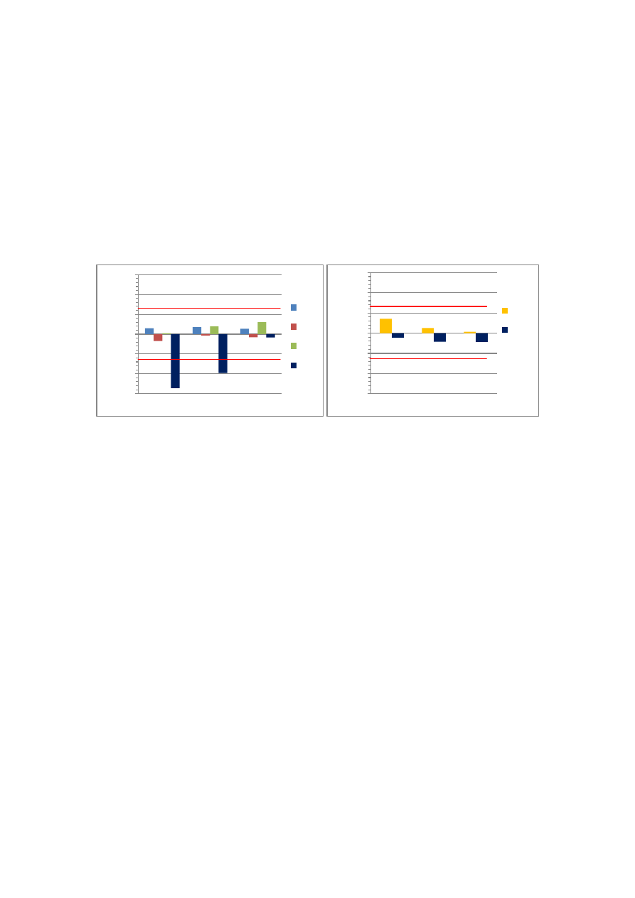
±0.0127 mm that represents ±0.13% hole size error. Figure 9(a) and (b) show that all the
drilling tests produced hole sizes within acceptable tolerance limits, except the COD at
MRRs 11.4 and 17.1 cm³/min. Such excessive errors could be a consequence of the
helical path errors generated by the controller of the machine tool and/or the deflection
of the tool under the action of the tangential force. However, the holes produced by
COD at MRR 22.8 cm³/min were within tolerance. This could be due to the
compensation effect of tool dynamics. Figure 9 (b) shows that COD produced hole sizes
within acceptable tolerance limits at MRR of 1.9 to 3.8 cm³/min due to lower helical
path errors and tool dynamics effects at this range of MRR.
Figure 9; Hole size error for (a) COD and conventional drilling under dry, air, and
MQL conditions. (b) COD and SAOD at lower MRR levels
CONCLUSIONS
The following conclusions can be drawn from this study:
1. Using MQL with conventional drilling resulted in a drilling thrust force reduction
of 17% to 20%, compared to the dry and air cooled conventional drilling.
However, such reduction was not sufficient to eliminate the exit delamination. On
the other hand, the COD and SAOD produced delamination-free holes.
2. Using MQL and air cooling with conventional drilling resulted in up to 45% and
30% temperature reduction, respectively. This suggests that using MQL and air
cooling becomes more essential at high MRR ranges where the exit temperatures
of dry conditions exceed the material decomposition temperature. The COD
resulted in a temperature reduction of up to 60% compared to conventional dry
drilling at high MRRs. The SAOD resulted in significantly higher temperatures
compared to COD at low MRR ranges. However, further design considerations of
the superabrasive tool can significantly enhance the performance of the process.
3. The COD conducted at low MRR resulted in superior hole surface quality. On the
other hand, the COD at high MRR produced lower surface quality compared to
conventional drilling due to helical path errors and tool dynamics effect. MQL
and air cooling did not show a significant improvement, in terms of surface
quality. The SAOD produced significantly lower surface quality as a result of the
relatively coarse diamond grains used.
-0.3
-0.2
-0.1
0.0
0.1
0.2
0.3
H
o
le
Size
E
rro
r
(%
)
Material Removal Rate (cm³/min)
Dry
Air
MQL
COD
-0.3
-0.2
-0.1
0.0
0.1
0.2
0.3
H
o
le
Size
E
rro
r
(%
)
Material Removal Rate (cm³/min)
SAOD
COD
(a)
(b)
1.9 2.85
3.8
11.4
17.1 22.8
Upper limit
Lower limit
Upper limit
Lower limit

4. All the drilling tests produced hole sizes within acceptable tolerance limits, except
the COD tests conducted at the medium MRR range. This was attributed to the
helical path errors and tool deflection under the action of the tangential force.
5. The COD produced delamination-free holes, with superior surface quality and
significantly reduced temperatures. However, multi-axis machine centers have
limitations on performing the COD at high MRR.
ACKNOWLEDGEMENTS
This work was conducted under the partial financial support of the Natural Sciences and
Engineering Research Council of Canada (NSERC), which the authors greatly
appreciate. The authors would like to acknowledge the support of the Aerospace
Manufacturing Technology Centre (AMTC), Institute for Aerospace Research (IAR),
National Research Council Canada (NRC), where the experiments were conducted.
REFERENCES
[Lindqvist et al., 2001] Lindqvist, R.; EriKsson I.; Wolf M.; "Orbital drilling of
sandwich constructions for space applications"; In: Proceedings of the 2001 SAE
Aerospace Automated Fastening Conference; Seattle 2001
[Persson et al., 1997] Persson E.; Eriksson I.; Zackrisson L.; "Effects of hole
machining defects on the strength and fatigue life of composite laminates";
Composites Part A: Applied Science and Manufacturing; Vol. 28 (2); pp. 141-151;
1997; ISSN 1359-835X
[Iyer et al., 2007] Iyer R.; Koshy P.; Ng E.; "Helical milling: An enabling technology
for hard machining precision holes in AISI D2 tool steel"; International Journal of
Machine Tools and Manufacture; Vol. 47(2); 2007; pp. 205-210; ISSN 0890-6955
[Colligan et al., 1999] Colligan K.; Ramulu M.;"Edge trimming of graphite/ epoxy with
diamond abrasive cutters"; vol. 121(4); pp. 647-655; ISSN 1087-1357
[Tasdelen et al., 2008] Tasdelen B.; Wikblom T.; Ekered S.; "Studies on minimum
quantity lubrication (MQL) and air cooling at drilling"; Journal of Materials
Processing Technology; Vol. 200(1-3); pp. 339-346; ISSN 0924-0136
[Rawat et al., 2009] Rawat S.; Attia H.; "Characterization of the dry high speed drilling
process of woven composites using Machinability Maps approach"; CIRP Annals -
Manufacturing Technology, Vol. 58(1); 2009;pp. 105-108; ISSN 0007-8506
[Langella et al., 2005] Langella A.; Nele L.; Maio A.; "A torque and thrust prediction
model for drilling of composite materials"; Composites Part A: Applied Science
and Manufacturing; Vol. 36(1); 2005; pp. 83-93; ISSN 1359-835X
[Ho-Cheng et al., 1990] Ho-Cheng H.; Dharan C.; "Delamination During Drilling in
Composite Laminates"; Transactions of ASME Journal of Engineering for
Industry; Vol. 112(3); 1990; pp. 236–239
[Ahmad et al., 2009] Ahmad J.S.; "Conventional Machining of FRPs"; in: Machining
of Polymer Composites; Springer 2009; ISBN 978-0-387-35539-9
Wyszukiwarka
Podobne podstrony:
A comparative study on heat pump, microwave and freeze drying of fresh fruits
32 425 436 Ifluence of Vacuum HT on Microstructure and Mechanical Properties of HSS
Effect of heat treatment on microstructure and mechanical properties of cold rolled C Mn Si TRIP
Comparative study on synteny between yeast ane vertebrates
On Will and the Practice of Will Thelema101
Brief Study on Domestication and Foreignization in Translation
Study Flavanoid Intake and the Risk of Chronic Disease
An exegetical study on Divorce and Remarriage (Matt 19 9) by John Murray
The Structure and Heat Treatment of Low Carbon Steel
comparative study islamic and conventional banking
Comparative study based on exergy analysis of solar air heater collector using thermal energy storag
A comparative study of english and chinese idioms with food names
Sandra Marco Colino Vertical Agreements and Competition Law, A Comparative Study of the EU and US R
A comparative study of inverter and line side filtering schemes in the dynamic voltage restorer
Code Red a case study on the spread and victims of an Internet worm
comparative study of homelessness in UK and Japan
więcej podobnych podstron