22/05/2006
TECHNICAL INFORMATION
Instructions for the mounting of the auxiliary controls
Form:TEC-ELEC-02-EN
DHOLLANDIA
1. Introduction to the subject
•
The issue of the choice and position of the auxiliary controls deals with the protection of the toes and
limbs of the operator working on or around the tail lift platform. It deals with the risk that the operator
might squeeze, crush or injure his toes or limbs in any different way between the sharp edge of the ris-
ing or closing platform, and the rear cross member of the cargo floor of the vehicle; or between the low-
ering or opening platform and the ground.
•
It is generally accepted that the foot control with compulsory 2-feet operation provides an efficient
remedy against the risk of crushing or injury, since it immobilises both feet of the operator on a prede-
termined and safe location on the platform (this is the buttons of the foot control unit), which the manu-
facturer needs to fit in a safe zone.
•
Whenever the foot control option is not adopted, the wander lead with spiral cable and the
fixed interior controls may only be used when the following safety working conditions are com-
plied with:
Fig. 1
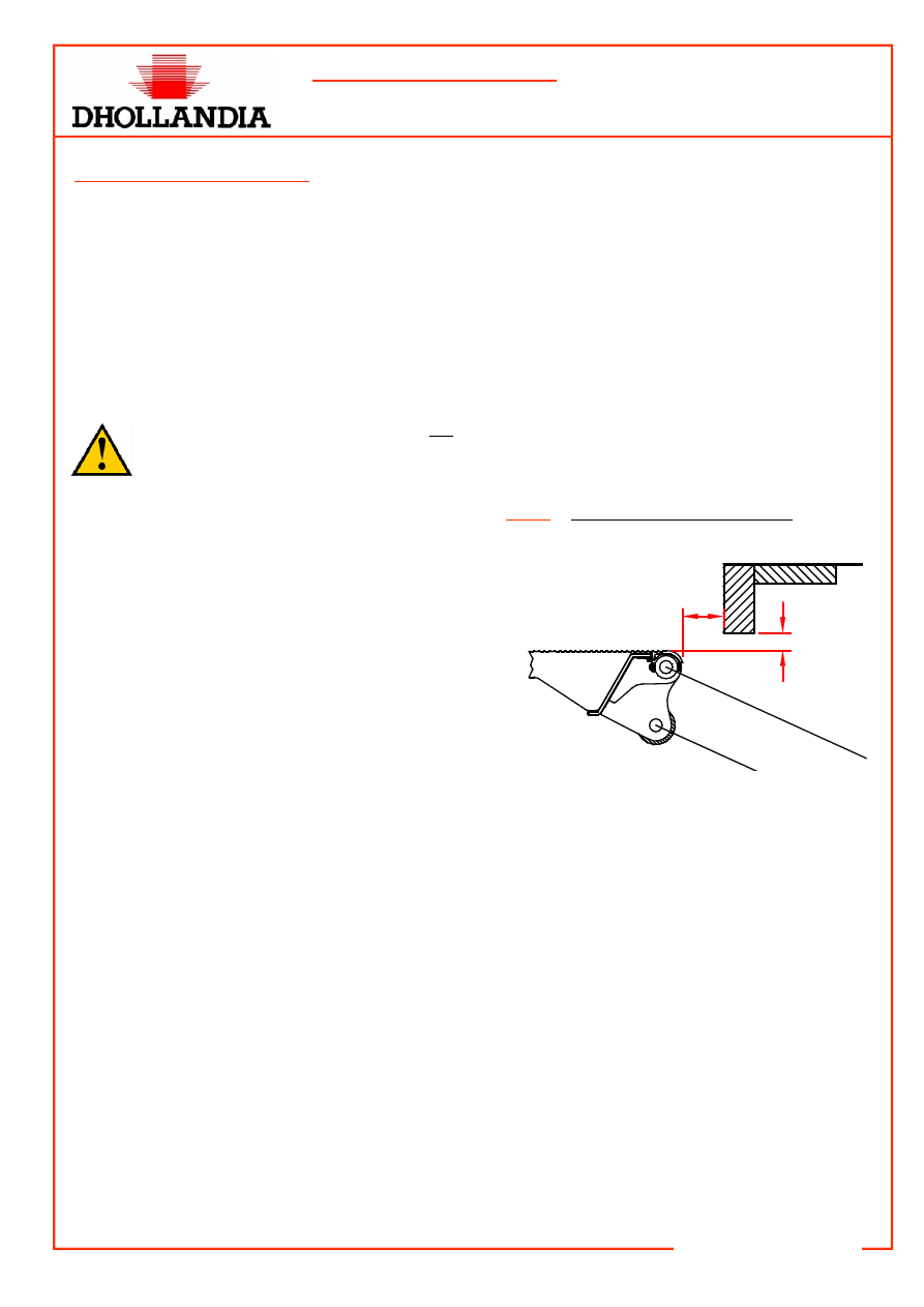
Toe protection acc. to EN811
1.
The interface between the lift platform and the
back end of the vehicle body must be de-
signed and constructed in such a way, that for
every vertically measured open gap “e” of
maximum 35 mm, there is a horizontal safety
distance “sr” of minimum 80 mm (EN811).
(See fig. 1).
The gap “e” of maximum 35 mm is
based on the height of the toe, and is measured
from the top side of the lift platform to the under-
side of the rear cross member of the cargo floor.
The safety distance “sr” is based on the front ar-
ticulation of the foot, and is measured from the
rear face of the rear cross member of the cargo
floor to the front edge of the lift platform.
e
O 35
sr
P 80
sr
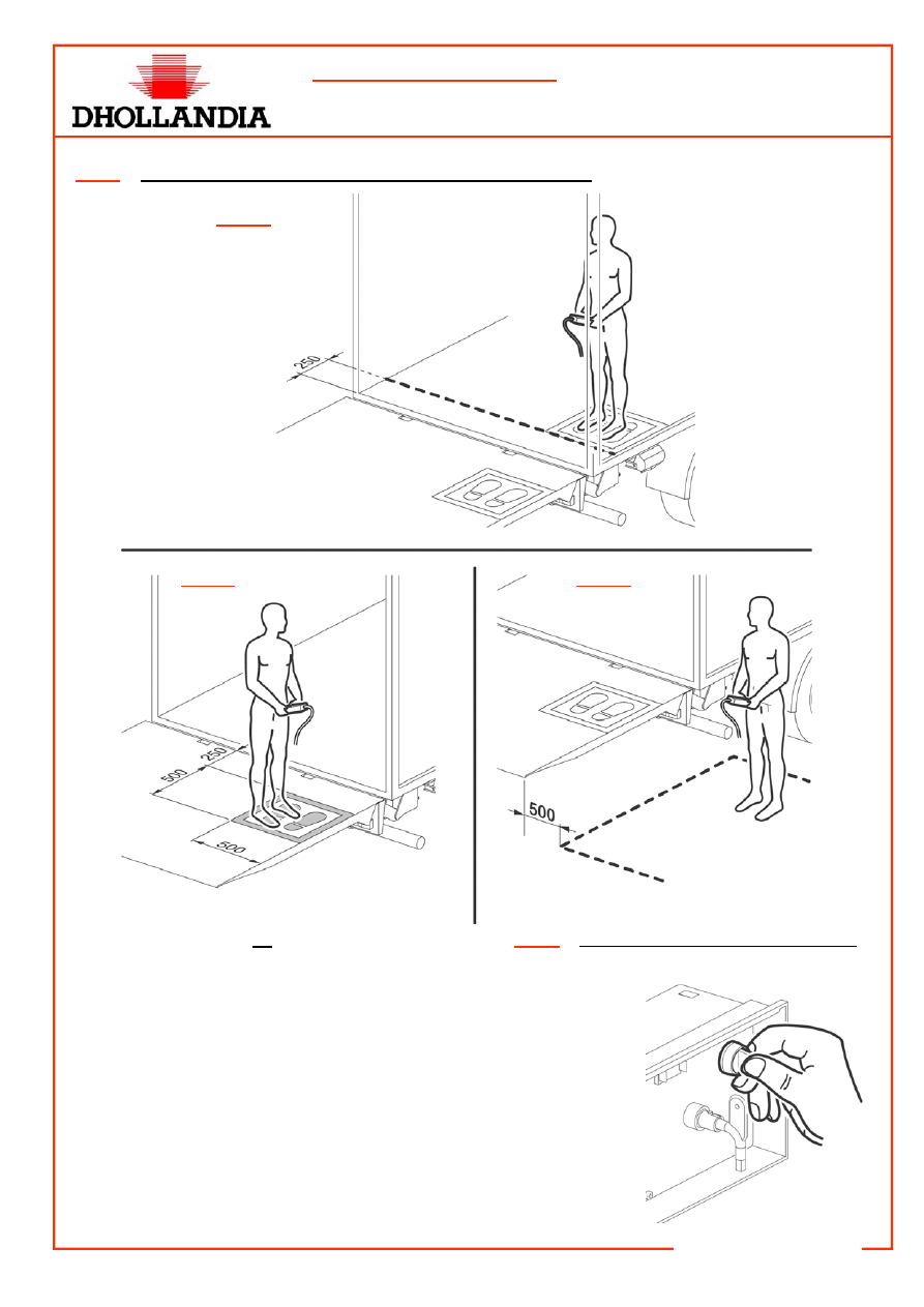
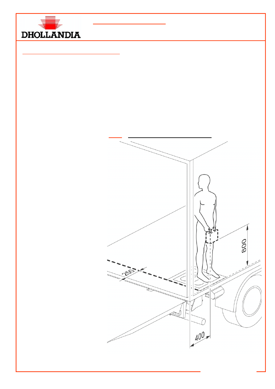
2. For working the auxiliary controls from the platform, the platform must be equipped with a clear and
permanently marked safe-working zone of 500x500 mm, that is minimum 250 mm removed from
the hazardous edge between the lift platform and back end of the vehicle. See fig. 2a. It is strongly
recommended to disallow the use of the fixed interior control from an operator’s position on the plat-
form itself.
3. Inside the vehicle body, the auxiliary controls may only be used from a clear and permanently
marked safe-working zone of 500x500 mm, that is minimum 250 mm removed from the hazardous
edge between the lift platform and the back end of the vehicle. See fig. 2b.
4. The operator of the tail lift must be duly informed about the safety instructions of tail lift use included
in the user’s manual, and must master all safety aspects. He must carry clear instructions from his
employer to work from the safe-working zone only.
5. Whatever option is adopted, it must comply with the safety directives EN1756 and EN811, and it
must have passed the installer’s risk analysis on the vehicle with positive result.
6. On the ground, the wander lead with spiral cable may only be used from a safe-working zone that is
minimum 500 mm removed from the side edge of the platform.. See fig. 2c.
22/05/2006
TECHNICAL INFORMATION
Instructions for the mounting of the auxiliary controls
Form:TEC-ELEC-02-EN
DHOLLANDIA
Fig. 2
Technical conditions for the use of the auxiliary control units
Fig. 2a
Fig. 2b
Fig. 2c
Fig. 3
Selection switch on the control panel
•
The power supply to all auxiliary control units should
always be linked into the selection switch on the
control panel of the external control box. See fig. 3.
This can be done:
1. Either by direct connection in the control box to
the relevant NO electric contact behind the selec-
tion switch;
2. Or in the hydraulic power pack to the foreseen
electric core coming from the selection switch on
the control panel.
•
See following wiring diagrams for further info:
Extra-S006-S076 CANNON PLUG-2006-01.dwg
Extra-S006-S090-S076 CANNON PLUG-2006-01.dwg
Extra-S075-S090-S076 CANNON PLUG-S070-2006-01.dwg.
22/05/2006
TECHNICAL INFORMATION
Instructions for the mounting of the auxiliary controls
Form:TEC-ELEC-02-EN
DHOLLANDIA
2. Mounting of the foot controls
•
The foot controls are supplied premounted in the platform. The mounting of the foot controls is therefore
limited to the following points:
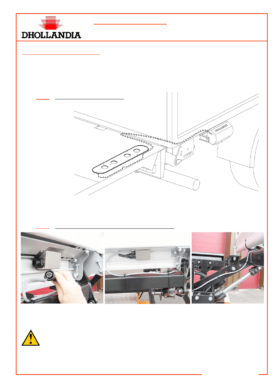
1. For standard foot controls (S006): lead the cable coming out of the platform, over the lift arms, to the
hydraulic power pack or the external control. See fig. 4.
2. For foot controls with CANNON plug (S075): connect the cable with
3
CANNON plug, premounted
in the hydraulic power pack, to the
4
CANNON plug, premounted on the lift platform.
Fig. 4
Connection of the foot controls
Fig. 5
Connection of the foot controls with a CANNON plug
•
Wire the foot control into the “selection switch” on the control panel of the external control box, accord-
ing to the wiring diagrams in the attachment. See also fig. 3.
•
After connecting the foot controls, test and check the free clearance of the cable of the foot
controls in all positions of the platform, to ascertain that it cannot get damaged during the
different movements (open, lower, lift, close) by the moving parts of the tail lifts or by the chas-
sis of the vehicle.
•
In order to increase the stability of the operator on the platform, mount a hand grip on the rear frame of
the vehicle body, onto which the operator can hold during the lift and lower movements of the platform.
22/05/2006
TECHNICAL INFORMATION
Instructions for the mounting of the auxiliary controls
Form:TEC-ELEC-02-EN
DHOLLANDIA
3. Mounting of the wander lead with spiral cable
•
The wander lead with spiral cable can and should only be used under the technical safe working condi-
tions described under point 1 of this instruction manual.
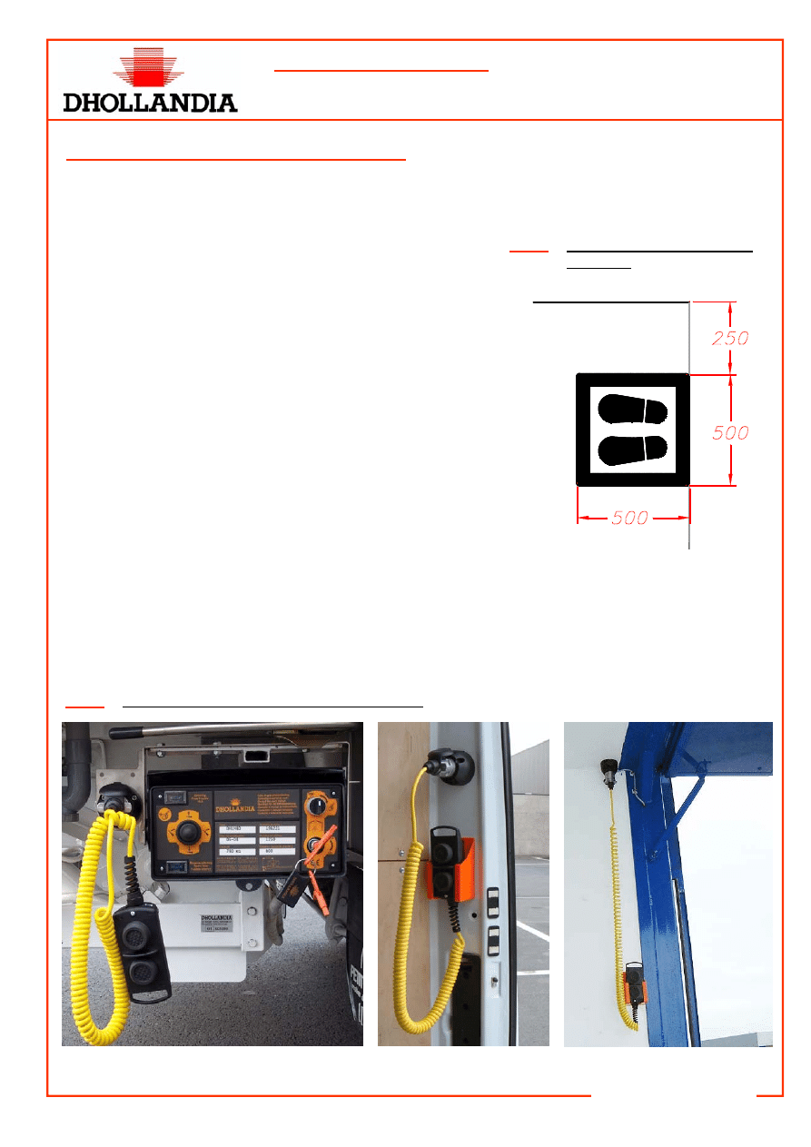
Fig. 6
Paint mask for the safe wor-
king zone
•
The wander lead with spiral cable can only be used:
1. On the platform, from a safe working zone of 500x500
mm, that is clearly and permanently marked at min.
250mm distance from the hazardous edge between the
platform and the rear cargo floor. (See fig. 2a).
2. Inside de vehicle body, again from a safe working zone
that is clearly and permanently marked at min. 250mm
distance from the hazardous edge between the platform
and the rear cargo floor. (See fig. 2b).
3. On the ground, from a safe working zone min. 500mm
removed from the side edge of the platform. (See fig.
2C).
•
In order to mark the safe working zone on the platform, you
can use a paint mask as shown in fig. 6.
•
In addition to marking the safe working zone on the platform
and / or on the vehicle cargo floor, it is recommended to
mark the hazardous areas at the end of the cargo floor and
the front of the platform in a different contrasting colour.
•
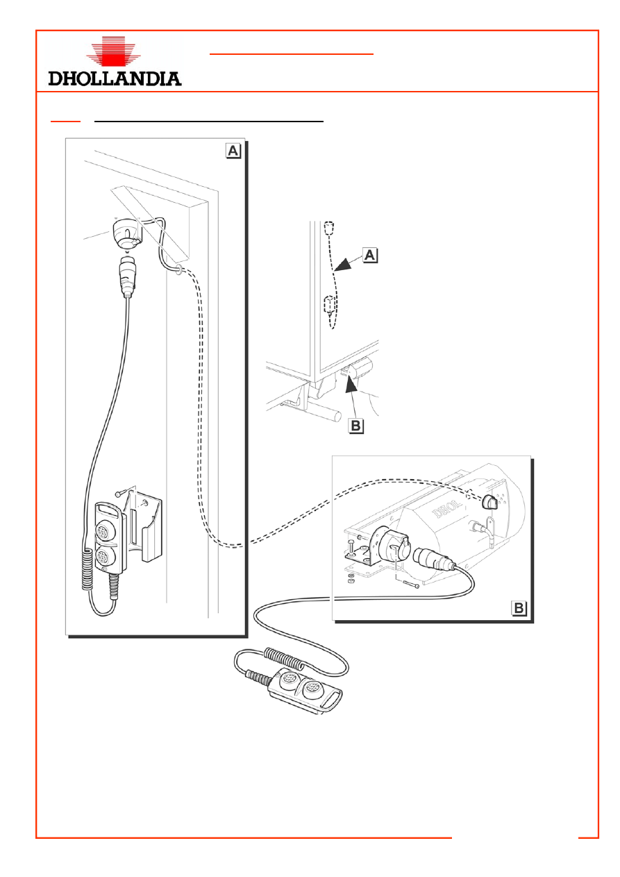
Preferably, the
3
plugs of the wander lead is mounted on one of the following locations:
1. On the mounting bracket of the external control box;
2. Inside the vehicle body, in the corner formed by the side panel and the roof of the body. In this case,
the wander lead can be stored in a purpose built holder supplied in the wander lead option kit.
See fig. 7,8.
Fig. 7
Mounting of the wander lead with spiral cable
22/05/2006
TECHNICAL INFORMATION
Instructions for the mounting of the auxiliary controls
Form:TEC-ELEC-02-EN
DHOLLANDIA
Fig. 8
Mounting of the wander lead with spiral cable
•
Wire the power supply to the wander lead into the selection switch on the control panel of the external
control box, according to the wiring diagrams in the attachment. See also fig. 3.
•
In order to increase the stability of the operator on the platform, mount a hand grip on the rear frame of
the vehicle body, onto which the operator can hold during the lift and lower movements of the platform.
22/05/2006
TECHNICAL INFORMATION
Instructions for the mounting of the auxiliary controls
Form:TEC-ELEC-02-EN
DHOLLANDIA
4. Mounting of the fixed interior controls
•
The fixed interior control can and should only be used under the technical safe working conditions de-
scribed under point 1 of this instruction manual.
•
In order to avoid crushing or injury of the toes or limbs, the fixed interior controls should only be used
inside the vehicle body, from a safe working zone of 500x500 mm that is clearly and permanently
marked, at a distance of min. 250 in front of the hazardous edge between the platform and the rear
cross member of the cargo floor of the vehicle. See fig. 9.
•
In addition to marking the safe working zone on the vehicle cargo floor, it is recommended to mark the
hazardous areas at the end of the cargo floor and the front of the platform in a different contrasting col-
our.
Fig. 9
Mounting of the fixed interior controls
•
Wire the power supply to the
fixed interior control into the se-
lection switch on the control
panel of the external control box,
according to the wiring diagrams
in the attachment. See also fig. 3.
Wyszukiwarka
Podobne podstrony:
2038 02 EN Citaro UE
LECTURE 02 EN
161TEC ELEC 01 EN
wfhss workshop20090325 lecture01 02 en
wfhss workshop20090325 lecture02 02 en
wfhss workshop20071206 lecture06 02 en
2048 02 EN Citaro CNG
wfhss training 2 02 en
2047 02 EN CapaCity
3032 02 EN Integro
wfhss workshop20071206 lecture01 02 en
131130 02 en
G2 4 PW EN sn pkp Rys 02
G2 4 PW EN nn um Rys 02 01
G2 4 PW EN sn nn Rys 04 02
1538373 2200SRM1065 (02 2004) UK EN
897509 2200SRM0524 (02 2001) UK EN
więcej podobnych podstron