How do I configure VLANS on my DFL Series Firewall and Layer 2 Managed
Switch?
Scenario:
VLAN 1 can communicate with VLAN 2 but VLAN2 cannot access VLAN 1. Both VLANS can access the internet.
DFL-210/800/1600:
• Lan Interface: 192.168.1.1
• VLAN1: 192.168.2.1
• VLAN2: 192.168.3.1
DGS-3024:
• “Default” VLAN--- VID-1---Ports 1-8
• “Vlan1” VLAN--- VID 2---Ports 9-24
• Port 1 will be tagged and connected to the DFL-210/800/1600.
Setup of DGS-3024
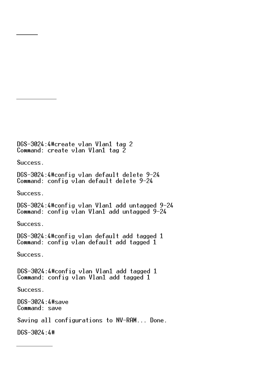
Step 1:From command line interface of DGS-3024:
DGS-3024# create vlan Vlan1 tag 2
DGS-3024# config vlan default delete 9-24
DGS-3024# config vlan Vlan1 add untagged 9-24
DGS-3024# config vlan default add tagged 1
DGS-3024# config vlan Vlan1 add tagged 1
DGS-3024# save
Setup of DFL-210
Step 1: Click on Objects and Interface Address’. Add New IP address’ for the following:
• VLAN1: 192.168.2.1
• VLAN2: 192.168.3.1

• VLAN1_net: 192.168.2.0/24
• VLAN2_net: 192.168.3.0/24
Step 2: Click on Interfaces and VLAN. Add New VLAN.
• Name: VLAN1
• Interface: lan
• VLAN ID: 1 • IP Address: VLAN1
• Network: VLAN1_Net
• Default Gateway: None
Click OK.
Step 3: Click on Interfaces and VLAN. Add New VLAN.
• Name: VLAN2
• Interface: lan
• VLAN ID: 2
• IP Address: VLAN2
• Network: VLAN2_Net
• Default Gateway: None
Click OK.
Step 4: Click on Objects and Interface Address’. Add New IP4 group.
• Name: All_Internal_Nets
• Select: lannet, VLAN1_net, VLAN2_net
Click OK.
Step 5: Click on Interfaces and select Interface Groups’. Add New Interface Group.
• Name: All_Internal_Interfaces
• Select: lan, Vlan1, Vlan2
Click OK.
Step 6: Click on Rules, IP Rules, Lan to WAN. Edit The following 4 Rules:
• drop_smb-all
• Allow_ping-outbound
• Allow_ftp-passthrough
• Allow_standard
Note: Each of the rules will need to be edited and have the new interface/nets applied.
Step 6: Click on Rules, IP Rules. Add New IP Folder (Optional).
• Name: Vlan_Rules
Click OK.
Step 7: Add new IP Rule.
• Name: Allow_VLAN1_to_VLAN2
• Action: Allow
• Service: All Services
• Schedule: None
• Source Interface: VLAN1
• Source Network: VLAN1_Net
• Destination Interface: VLAN2
• Destination Network: VLAN2_Net
Step 7: Click Configuration Tab and click Save and Activate.
Wyszukiwarka
Podobne podstrony:
How to configure fuel injectors on the pre CAN Duratorq HPCR
CISCO how to configure VLAN
How to Install Windows`XP on SATA
CISCO how to configure VLAN
How to Analyze People on Sight, by Elsie Lincoln Benedict and Ralph Paine Benedict
Creative Writing How To Write A Book On Anything In 14 Days Or Less
więcej podobnych podstron