H2 -1
Analog I/O Expansion Module
Temperature Input Module
Numeric I/O Expansion
7
6
8
9
Chapter 2 System Architecture
2.1
Single-Unit System of FB
S
-PLC
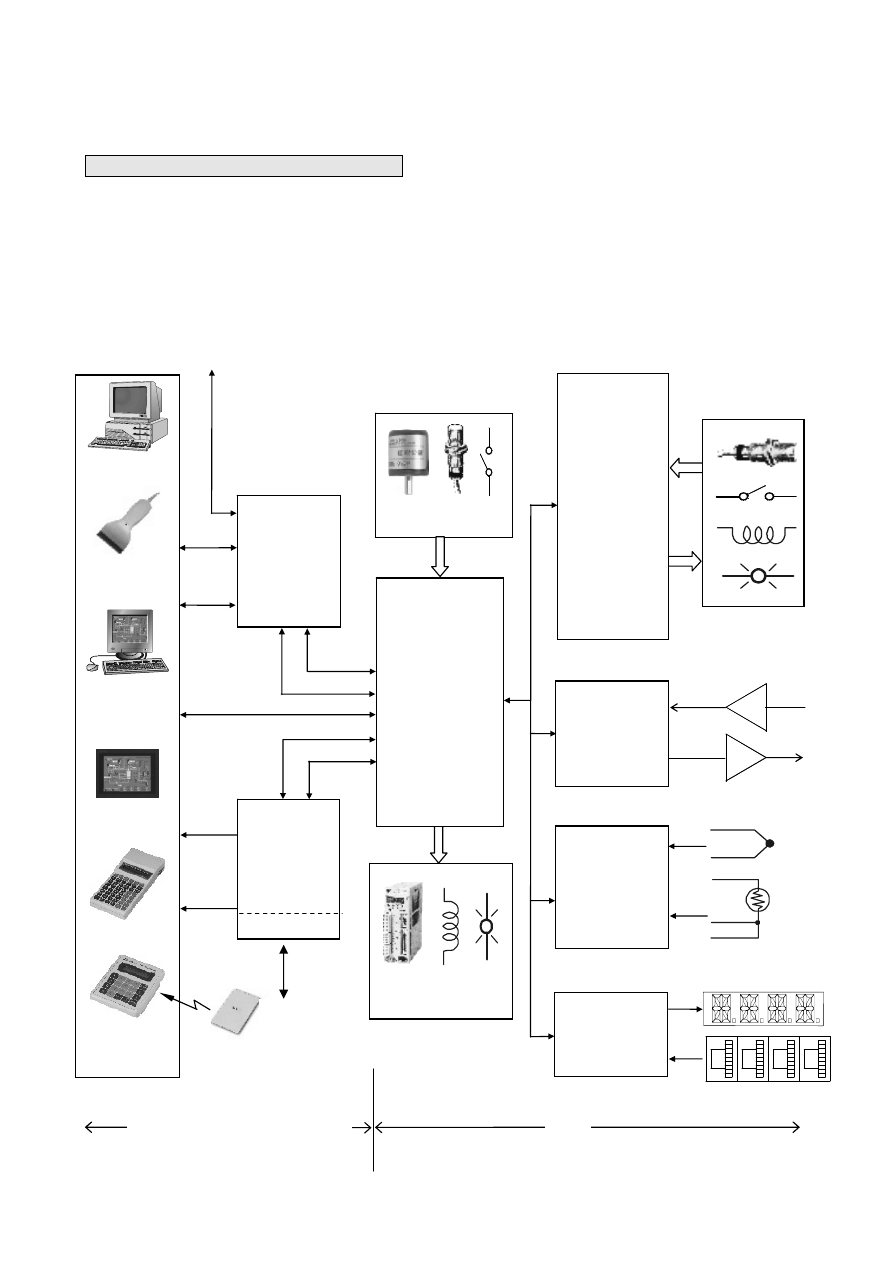
The Single-Unit system means a system built only by a single FBs-PLC and its expansion unit/modules and
communication boards/modules. Such system have a limited capability (refer), beyond that capability can incorporate
CPU communication via LINK function for expansions (please refer to the next paragraph). The figure below shows the
block diagram of the Single-Unit system of FBs-PLC, where, besides the available main units , the available
communication peripherals resources and I/O expansion resources are depict on the left and the right respectively.
Port1
Port0
Port2
Port3
Port1
Port4
(Por
t4
)
USB or
RS232
DO
Intelligent
Peripherals
DI
Digital I/O Expansion Unit/Module
AO
AI
Digital Output (DO)
Communication
Board
Main
Unit
Digital Input (DI)
Communication
Module
Ethernet (suffix “E” Module only)
Port3
Port1
Port2
Port4
Computer
Bar Code
Reader
Diagram Control
Man-Machine
Console
Man-Machine
Interface
FP-07C
FB-DAP(R)
:
FBs-CM25E
FBs-CM55E
FBs-CM22
FBs-CM55
FBs-CM25
Encoder
FBs-10MA/MC
FBs-14MA/MC
FBs-20MA/MC
FBs-24MA/MC
FBs-32MA/MC
FBs-40MA/MC
FBs-60MA/MC
FBs-20MN
FBs-32MN
FBs-44MN
FBs-24EA(P)
FBs-40EA(P)
FBs-60EA(P)
FBs-8EA
FBs-8EX
FBs-8EY
FBs-16EA
FBs-16EY
FBs-20EX
FBs-24EX
FBs-24EYT
Servo
FB
S
-TC2
FBs-TC6
FBs-RTD6
FBs-TC16
FBs-RTD16
FBs-6AD
FBs-2DA
FBs-4DA
FBs-4A2D
I/O
Peripheral (Communication)
Resources
TC
RTD
RFID
Card
FBs-7SG1
FBs-7SG2
FBs-32DGI
Ethernet
FBs-CB2
FBs-CB22
FBs-CB5
FBs-CB55
FBs-CB25
FB
S
-CBE
H2 -2
For the I/O of FB
S
-PLC, it can achieve a maximum of 256 point digital input (DI), 256 point digital output (DO), 64 word
numeric input (NI), and 64 word numeric output (NO). Combined with various special interface modules, it can directly
connect with devices such as Thermocouple, RTD, 7-segment LED display, and the Thumbwheel switch, which are
shown on the right in the above figure.
Regarding communication resources, the FBs-PLC hardware can accommodate up to 5 communication ports (with a
maximum speed of 921.6Kbps). In addition to providing the standard FATEK communication protocol, it also supports the
Modbus master/slave protocol or any user-defined protocol. This functionality easily renders the connections with
intelligent peripherals such as electronic scale, bar code reader, and various meters and gauges.
2.2
Formation of Multi-Unit System
By connections through communication ports and specific communication drivers, multiple Single-Unit PLC systems
can be integrated to achieve resources sharing among multiple PLC or PLCs and its host computer. It is described as
follows:
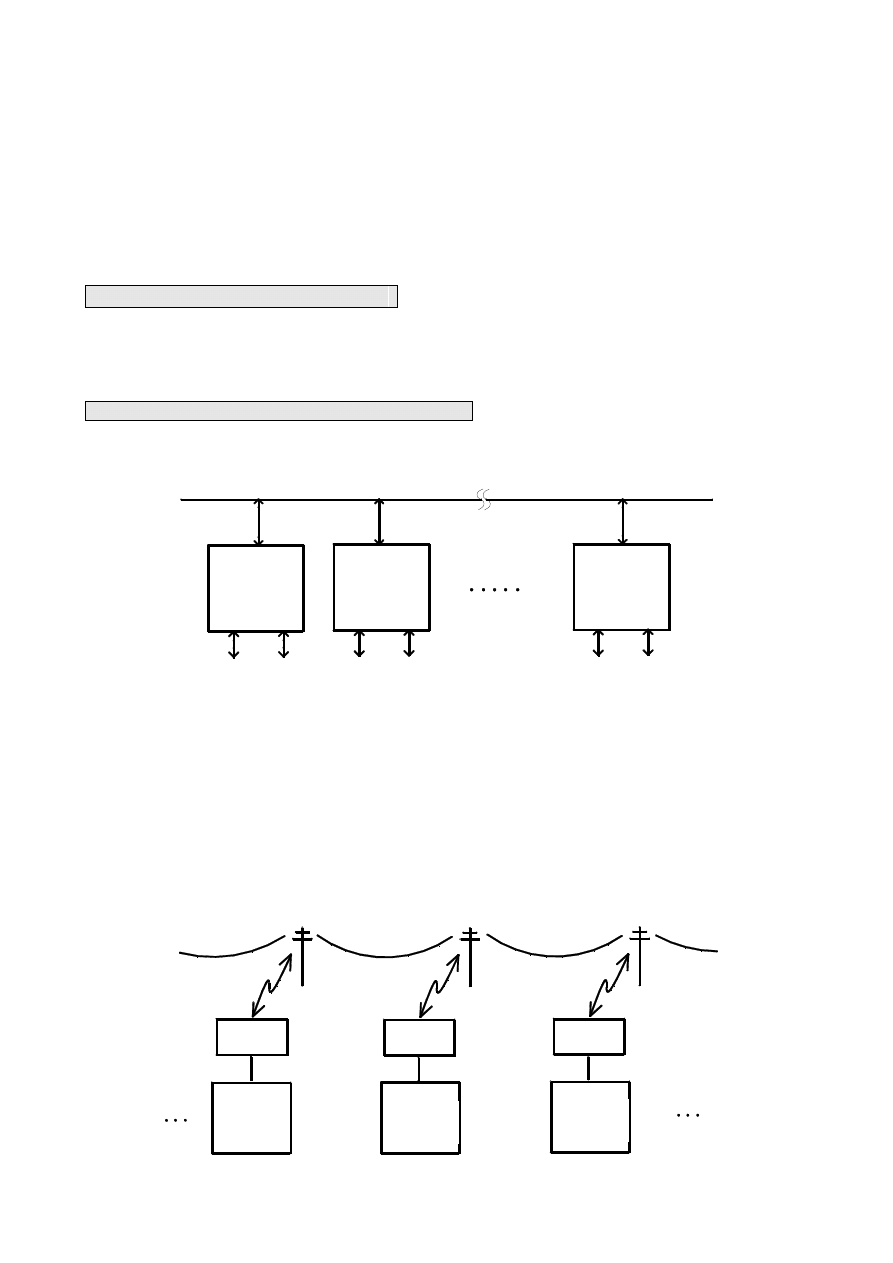
2.2.1 Connection of Multiple FBS-PLC (CPU Link)
RS-485
網路
FB
S
-PLC
主機
FB
S
-PLC
主機
FB
S
-PLC
主機
週邊
I/O
週邊
I/O
週邊
I/O
As shown in the figure, through the usage of high-speed RS-485 network, can easily establish the connections of 2~254
main units (each PLC with its own station number). All need to do is to write and execute CPU Link commands in one of
the main units, which makes it the Master of the CPU Link network. No other command is necessary for other Slave units.
The Master CPU will automatically collect the information or data in the specific areas of all units (including the Master)
and put it into the Common Data areas(CDM) of all units. Thus all the units connected by network can share the data for
each other and turning the finite Single-Unit system with limited I/O into a huge system.
FB
S
-PLC
主機
FB
S
-PLC
主機
FB
S
-PLC
主機
電話線路
MODEM
MODEM
MODEM
FBs-PLC
Main Unit
FBs-PLC
Main Unit
FBs-PLC
Main Unit
Telephone line
Peripherals
Peripherals
FBs-PLC
Main Unit
FBs-PLC
Main Unit
FBs-PLC
Main Unit
RS-485 Network
Peripherals
H2 -3
Besides the above area network connection, FBs-PLC can also be connected using MODEM via the phone line (either
leased line or public phone line) to form remote multiple PLC Link. (When using a public phone line, the Master PLC
will perform consecutive dialing for all its Slave PLC.)
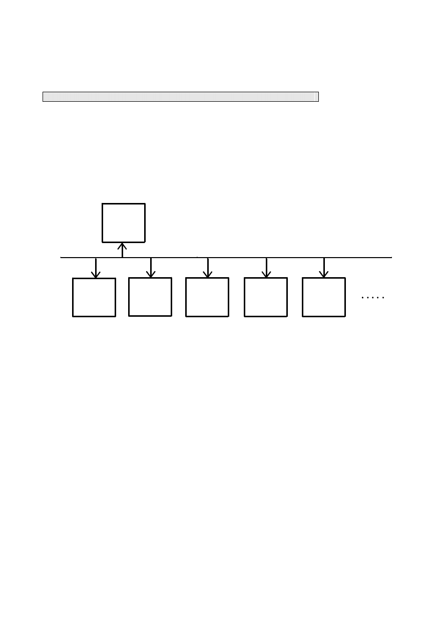
2.2.2 Connection FBs-PLC with Host Computer or Intelligent Peripherals
Any one of the five communication ports on FBs-PLC can be used to connect to an upper-level computer or other
systems, with this architecture, the FBs-PLC is playing the Slave role. FBs-PLC supports the FATEK and Modbus
protocol. Connection can be established as long as the upper-level computer or intelligent peripherals use either one of
the two protocols. In the application, in which driver for FATEK or Modbus is not available, FATEK also provide
standard DDE communication server, which enables FBs-PLC to connect with any computer system supporting DDE.
The following is the block diagram.
上 位
電 腦
永宏通訊驅動程式(third party)
Modbus 通訊驅動程式(third party)
DDE(FATEK Communication Sever)
FB
S
-PLC
FB
S
-PLC
FB
S
-PLC
FB
S
-PLC
FB
S
-PLC
Host
Computer
1 FATEK communication driver (third party)
1 Modbus communication driver (third party)
1 DDE (FATEK Communication Sever)
Wyszukiwarka
Podobne podstrony:
więcej podobnych podstron