Drill Press Table
Turn your drill press table into a
woodworking table ina few hours.
Despite the fact that your drill press is
designed mostly for poking holes in sheet
metal, it has many uses in a woodshop.
It's a mortiser, a spindle sander, it bores
huge holes, and -- of course -- drills holes
at perfect right angles to the table.
Because the table on most drill presses is
designed for metalworking, it's hardly
suited for these tasks. So I built this add-
on table with features that will turn your
drill press into a far friendlier machine:
First, a fence that slides forwards and
backwards as well as left and right on
either side of the quill. This last feature
also uses the drill press' tilting table
feature with the auxiliary table for angled
drilling.
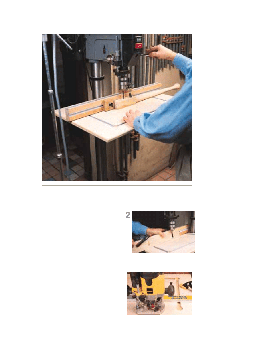
Another view of the drill-press table. Here I'm
cutting pocket holes in a table apron.
ROUT THE GROOVE The grooves for the T-
Built-in stops (both left and right) that
attach to the fence for repetitive
procedures such as doweling or chain
drilling for mortises.
Hold-downs that can be used on the fence
or on the table for any procedure.
The sizes given in the Schedule of
Materials are for a 14" drill press, with the
center falling 9" from the rear edge of the
table, with a 2" notch in the back to
straddle the column. Adjust the center
location and overall size of the table to
match your particular machine.
Start With the Base-ics
The base platform for the table is made
from 3/4" plywood, which should be void-
free. Again, adjust the size as necessary
to fit your drill press. First you need to get
the table ready for the T-track, which is
what holds the fence and hold-downs in
place. Start by locating the four recessed
holes that allow the T-slot mechanism to
slip into the track without disassembling
the mechanism. Each hole is 1-1/2" in
diameter and 3/8" deep.
Next, locate the grooves in the center of
the holes and use a router with a 3/4"-
wide straight bit to cut the grooves to a
3/8" depth. The T-slot track should fit into
the grooves with the top surface just
below that of the plywood table. The
grooves should be as parallel as possible
to one another to allow smooth movement
of the fence.
Replaceable Center
Now cut the hole for the 4" x 4"
replaceable insert. First locate and mark
the position centered on your table, then
mark in from that line by 3/8" to locate
your cutting line. Drill clearance holes in
two corners of the square, then use a
jigsaw to cut out the center piece. Next,
determine the thickness of the material
you will use for your insert (the 3/8"-thick
Baltic Birch we used is actually metric and
shy of 3/8") and set a 3/8" piloted
rabbeting bit in a router to a height to hold
the insert flush to the top surface of the
table.
While your jigsaw is still out, locate, mark
and cut out the notch in the back of the
table. This allows the table to move closer
slot track allow the fence to be used left-
to-right and front-to-back on the table to
tak
e of
e advantage of the built-in tilting featur
the existing table.
RABBET FOR THE INSERT After
cutting the hole with a jigsaw, the
ope
d
ning is rabbeted using a bearing-pilote
router bit. Then chisel the corners square
and fit the replaceable center tightly into the
rabbet. Make a couple extras.
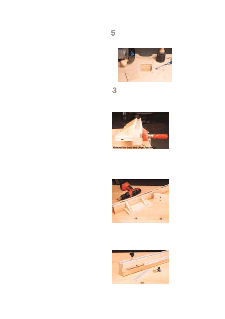
ROCK SOLID The fence is made of a
sturdy, stable hardwood. Cut a groove the
length of the top and face of the fence. The
grooves support T-slot tracks, which can be
used for stops, hold-downs and other
accessories.
FENCE BRACES The fence is supported by
two simple brackets screwed to the rear of
the fence. The location of the triangular
braces is important to the track orientation,
so follow the diagrams carefully for location.
to the drill press' post and tilt without
interference.
As a final friendly touch on the table, I
used a 3/8" roundover bit in my router to
soften all the edges on the table, both top
and bottom. You'll get fewer splinters if
you do this.
Milling the Fence
The fence is the heart of the table, and the
wood should be chosen for durability and
straightness. Quartersawn hardwood,
carefully surfaced and planed, will do
nicely. After cutting the fence to size, use
a dado stack to mill two 3/8"-deep by 3/4"-
wide grooves in the fence. The first is
centered on the top surface of the fence,
and as in the grooves in the base
platform, a piece of T-slot track should be
used to confirm that the groove is deep
enough to allow the track to fit just below
the surface of the wood. The second
groove is then cut centered on the face of
the fence. One other bit of table saw work
is the 1/8" x 1/4" wide rabbet cut on the
inside bottom edge of the fence. This
rabbet allows dust and debris to be
pushed into the rabbet, so your work will
fit against the fence.
One option that I considered was adding
an indexing tape measure on the fence.
Every time the table is moved the tape
would need to be readjusted to zero, and
for the infrequent use the tape would see I
decided against it. A stick-on tape can
easily be added to the fence face if that's
more to your personal taste and needs.
Fence Support Braces
Unlike the fence on a router table, the
fence on a drill press table won't see a lot
of lateral pressure. So the main purpose
of the braces is to hold the fence square
to the table at the drilling point. In my case
I've also given the braces the job of
mounting the fence to the table.
Start by cutting the two base plates and
the four braces to size. The braces are
triangles with the bottom edge 3" long and
the adjoining right angle edge 1-7/8" long.
The third side is determined by simply
connecting the corners. Locate the braces
on the base plates according to the
diagrams and pre-drill and countersink
3/16" diameter holes in the base plates to
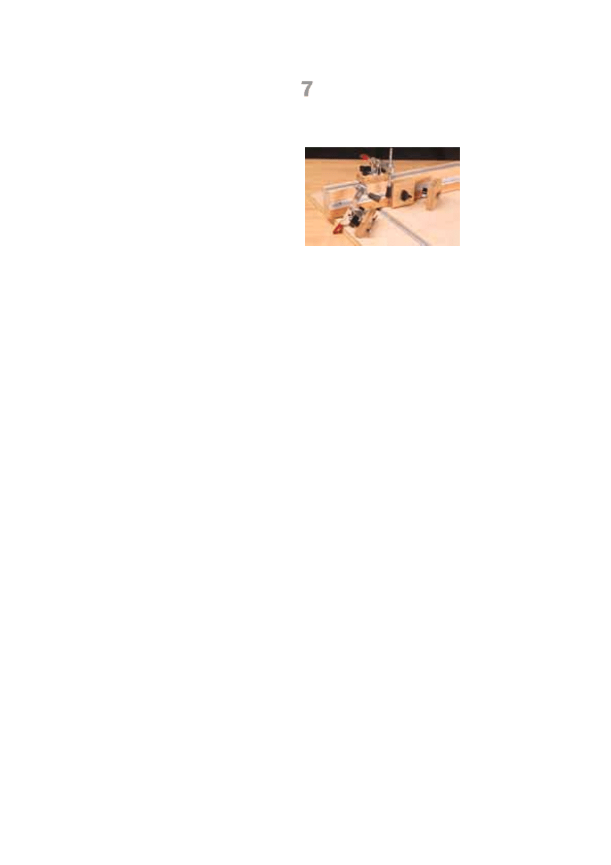
LAYING TRACKS Install the T-slot tracks
in the grooves with flat head screws
countersunk into the track. The braces are
attached to the fence by screwing through
the face groove prior to attaching the T-slot
track.
HOLD IT The hold-downs and stops are
made from 3/4" hardwood. To make the
guide to hold the stops square to the fence,
cut a 1/16" x 1-1/8" rabbet on both sides of
the inside face.

attach the braces to the plates.
To mount the support braces to the fence,
again refer to the diagrams to locate the
proper spacing on the fence. Then drill
and countersink screw holes through the
face groove in the fence. Clamp the brace
to the fence and screw the brace in place.
With the braces attached to the fence, use
the T-slot fastener locations on the
diagrams as a starting point for drilling the
holes in the base plates, but check the
location against your table for the best fit.
Two holes are drilled in each plate to allow
the fence to be moved to the
perpendicular position (either to the right
or left of the quill), by simply relocating
one of the T-slot fasteners. Check each
hole in relationship to that position.
Attaching the Track
Assuming you purchased the 24" lengths
of track listed in the Schedule of Materials,
you should be able to cut the tracks for the
table first, leaving fall off that can be
added to the two remaining full length
tracks to give you the necessary 30"
lengths of track for the fence. When
attaching the track, first pilot drill the hole
in the center of the track (a groove is
provided in the track to simplify that
location), then use a countersink to widen
the hole to accommodate a #4 x 5/8" flat
head screw. Keeping the screws as flush
as possible to the inner surface of the
track will make the stops and hold-downs
move much easier.
Finishing Touches
Stops and hold-downs designed for use in
T-tracks make the drill press most useful.
The stops are simply square blocks of
wood with one side milled to leave an
indexing strip that fits into the slot on the
T-slot track. By using the saw to cut tall
but shallow rabbets on two edges of each
block, the stops are completed fairly
easily. For safety, run the rabbet on a
longer 2-1/2" wide piece of wood, then cut
the stops to square afterward. The T-slot
fasteners are simply inserted into a 1/4"
hole drilled in the center of each stop
block.
The hold-downs are simply blocks of wood
with DeStaCo clamps mounted to the top.
Each block is drilled for two T-slot

fasteners, one on either end. Then the
clamp is screwed to the top surface of the
block. While the DeStaCos are good for
this application, they aren't as versatile as
I wanted. I replaced the threaded-rod
plunger with longer all-thread (1/4" x 36) to
provide maximum benefit from the clamps.
The rubber tip of the plunger is important
to the function of the clamp, and if you can
manage to reuse the existing tip it's very
helpful. If not, I found rubber stoppers in a
variety of sizes in the local Sears
hardware store. After carefully drilling a
1/4"-diameter hole two-thirds of the way
into the stopper I was able to screw it onto
the rod with little difficulty.
Attaching and Personalizing
The table should attach easily to your
existing drill press table using four lag
bolts countersunk flush into the surface of
the auxiliary table. Once attached you
should find that the auxiliary table
overhangs the metal table quite a bit. One
personalized touch I want to suggest is
adding small drawers to the underside of
the table to store bits, wrenches and
chuck keys. PW
2
1
/
2
"
1
/
8
"
1
/
8
"
11
/
16
"
1
/
4
"
1
1
/
4
"
3"
1
/
8
"
1
3
/
4
"
1
/
8
"
3
/
4
"
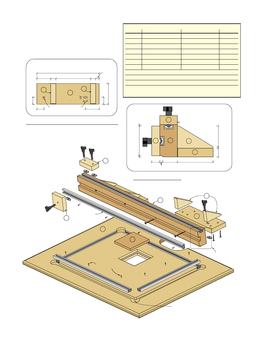
Detail of Fence Profile
See detail above
A
B
C
D
E
F
G
#4 x
3
/
8
" screws
See detail of brace above
T-slot track
1"
1"
2"
1"
2"
3
/
4
"
5"
3
/
4
"
1
/
2
"
3"
9"
1
/
2
"
1
/
4
"
1
/
4
" hole
Plan detail of hole locations for base plate
Location of base plate braces
Hole locations
E
F
B
D
C
Holes are centered 3" in from
the front and back and 4
1
/
2
"
from either side.
D
C
D
Right side shown, left is mirror image
Schedule of Materials: Drill press table
No. Lett.
Item
Dimensions T W L
Material
1
A
Platform
3
⁄
4
" x 20" x 29"
Plywood
1 B
Fence
1
1
⁄
2
" x 2
3
⁄
4
" x 30"
Hardwood
2
C
Fence base plates
3
⁄
4
" x 3" x 9"
Plywood
4
D
Base plate braces
3
⁄
4
" x 3" x 1
7
⁄
8
"
Hardwood
2
E
Stops
3
⁄
4
" x 2
1
⁄
2
" x 2
1
⁄
2
"
Hardwood
2
F
Hold-down plates
3
⁄
4
" x 1
1
⁄
2
" x 3"
Hardwood
1
G
Insert plate
3
⁄
8
" x 4" x 4"
Plywood
2
Part #88F05.02 DeStaCo clamps — $14.50 ea.
6
Part #12K7901 24" T-slot track — $4.95 ea.
8
Part #00M5102 1
1
⁄
8
" 3-wing knobs — $6 for 10
8
Part #05J2115 T-nuts — $1.15 for 10
All hardware available from Lee Valley 800-871-8158
Wyszukiwarka
Podobne podstrony:
Drill Press Table
Drill Press Table
(Ebooks) DIY Woodwork Plans Drill Press Table
Drill Press Table 1
Plans for radial drill press
Premier Press Beginning DirectX 9
oak dining table
Beijing Language University Press HSK Answer Form A
Focke Wulf Fw 190 A F G cz 2 (AJ PRESS Monografie Lotnicze 018)
Coffee Table 1
table style2, ♥Dokumenty
table cellspacin5, ❀KODY RAMEK I INNE, Ramki
table border (2)
Foresight Resolution Table
Chess Table
więcej podobnych podstron