
Operating instructions
Flow monitors
SI5010
SI5011
704332 / 02
08 / 2010
UK

2
Contents
1 Safety instructions ������������������������������������������������������������������������ 3
2 Functions and features ����������������������������������������������������������������� 4
2�1 Application area ������������������������������������������������������������������������ 4
2�2 Operating principle flow monitoring ������������������������������������������� 4
3 Installation ������������������������������������������������������������������������������������ 5
3�1 Installation location �������������������������������������������������������������������� 5
3�2 Sources of interference in the pipe system ������������������������������� 6
3�3� Mounting operation ������������������������������������������������������������������� 6
4 Electrical connection��������������������������������������������������������������������� 7
5 Operating and display elements ��������������������������������������������������� 7
6 Set-up and settings for water�������������������������������������������������������� 8
6�1 Change the switch point (optional) �������������������������������������������� 8
7�1 Low flow adjustment ������������������������������������������������������������������ 9
7�2 Configure the switching output �������������������������������������������������� 9
7�3 Restore the factory setting (reset) ������������������������������������������� 10
7�4 Lock / unlock the unit ��������������������������������������������������������������� 10
7�5 Remote adjustment ����������������������������������������������������������������� 10
8 Error during adjustment �������������������������������������������������������������� 10
9 Operation ������������������������������������������������������������������������������������ 11
10 Maintenance ����������������������������������������������������������������������������� 11
11 Scale drawing ��������������������������������������������������������������������������� 12
12 Technical data ��������������������������������������������������������������������������� 12
3
UK
Preliminary note
• An instruction is indicated by “►”:
Example: ► Check whether the unit operates correctly�
• A reaction to the action is indicated by ">":
Example: > LED 9 lights�
1 Safety instructions
• Please read the product description prior to set-up of the unit� Ensure that the
product is suitable for your application without any restrictions�
• The unit conforms to the relevant regulations and EC directives�
• Improper or non-intended use may lead to malfunctions of the unit or to un-
wanted effects in your application�
• That is why installation, electrical connection, set-up, operation and mainte-
nance of the unit must only be carried out by qualified personnel authorised by
the machine operator�
For the scope of validity cULus:
The device shall be supplied from an isolating transformer having a secondary
Listed fuse rated as noted in the following table�
Overcurrent protection
Control-circuit wire size
Maximum protective device rating
Ampere
AWG
(mm
2
)
26
(0�13)
1
24
(0�20)
2
22
(0�32)
3
20
(0�52)
5
18
(0�82)
7
16
(1�3)
10

4
2 Functions and features
2.1 Application area
The unit monitors the flow of liquid and gaseous media�
2.2 Operating principle flow monitoring
• The unit detects the flow speed to the calorimetric measuring principle and
switches the output:
-output closed if medium is flowing / output open if no medium is flowing�
This applies to the unit on delivery: output = normally open� In case of need you
can change the output to normally closed (→ 7�2)� It then applies: output open
if medium is flowing�
• If the flow speed increases, the switching status changes when the switch point
is reached�
• If the flow speed falls again, the switching status changes if the value "SP
minus hysteresis" is reached�
The hysteresis changes with the flow speed and it is essentially influenced by
the set monitoring range�
It is 2���5 cm/s for the setting 5���100 cm/s (= factory setting), it increases with
higher flow speeds�
• The typical response time of the unit is 1���10 s� It can be influenced by the
setting of the switch point:
-Low switch point = quick reaction with rising flow�
-High switch point = quick reaction with falling flow�
5
UK
3 Installation
Using process adapters the unit can be adapted to different process connections�
• Adapters have to be ordered separately as accessories�
A correct fit of the unit and ingress resistance of the connection are only
ensured using ifm adapters�
• For small flow rates ifm adapter blocks are available�
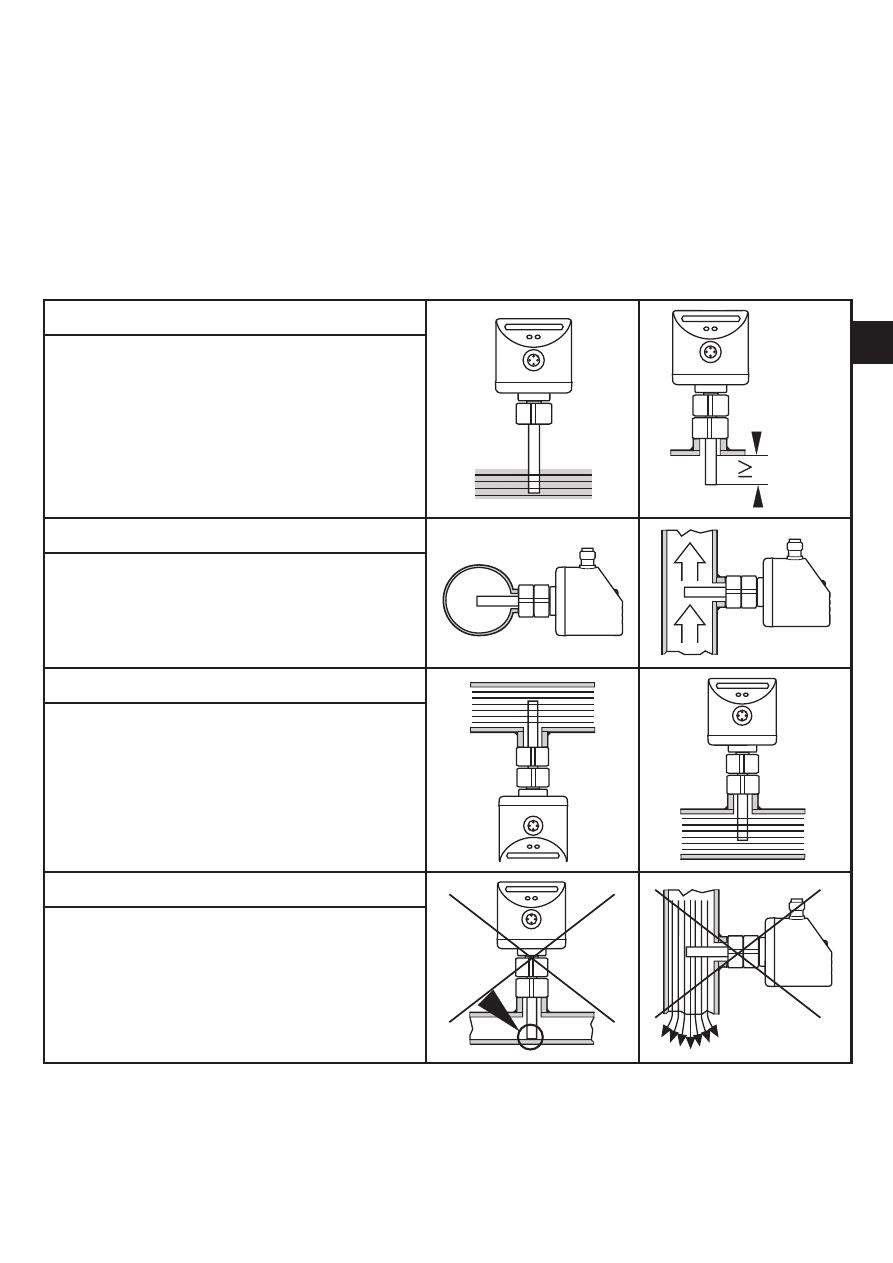
3.1 Installation location
General
• The sensor tip is to be completely sur-
rounded by the medium�
• Insertion depth of the sensor: minimum
12 mm�
Recommended
• For horizontal pipes: mounting from
the side�
• For vertical pipes: mounting in the rising
pipe�
Conditional
• Horizontal pipe /mounting from the bot-
tom: if the pipe is free from build-up�
• Horizontal pipe /mounting from the
top: if the pipe is completely filled with
medium�
To avoid
• The sensor tip must not be in contact
with the pipe wall�
• Do not mount in downpipes that are
open at the bottom!
6
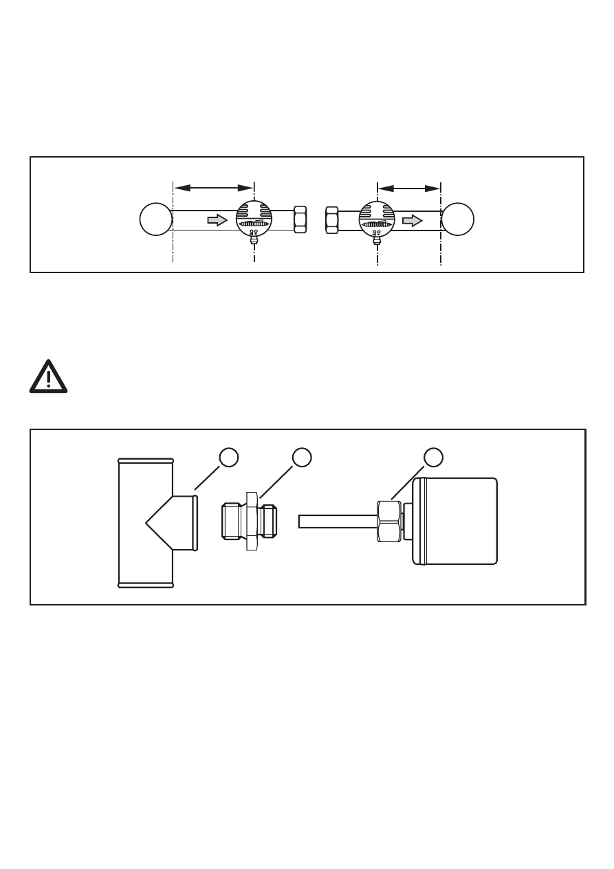
3.2 Sources of interference in the pipe system
Components integrated in the pipes, bends, valves, reductions, etc� lead to turbu-
lence of the medium� This affects the function of the unit�
Recommendation: Adhere to the distances between sensor and sources of
interference:
D = pipe diameter; S = sources of interference
3.3. Mounting operation
► Ensure that the system is free of pressure during installation�
► Ensure that no media can leak at the mounting location during installa-
tion�
► Grease the threads of the process connection (1), adapter (2) and nut (3)�
Note: The sensor tip (A) must not be in contact with grease�
► Screw the suitable adapter into the process connection�
► Place the flow monitor onto the adapter and tighten the nut� Tightening torque
25 Nm� Ensure that the unit is correctly oriented�
7
UK
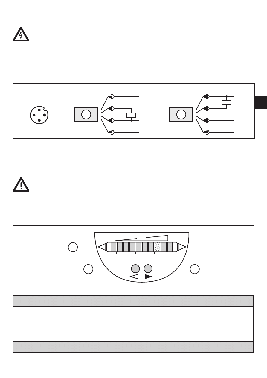
4 Electrical connection
The unit must be connected by a qualified electrician�
The national and international regulations for the installation of electrical
equipment must be adhered to�
Voltage supply to EN 50178, SELV, PELV�
► Disconnect power�
► Connect the unit as follows:
A: SI5010 (positive switching); B: SI5011 (negative switching)
Core colours of ifm sockets:
P: programming wire (for remote adjustment) → 7�5)
1 = BN (brown), 2 = WH (white), 3 = BU (blue), 4 = BK (black)
Use 4-wire connection cables without a link between pins 2 and 4�
With 3-wire sockets with a link between pin 2 and pin 4 switching of the
output stage triggers the remote adjustment�
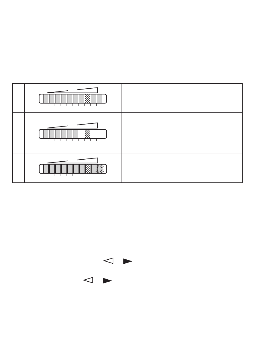
5 Operating and display elements
1: Operation display
• The green LEDs indicate the current flow (the LEDs 0 to 9 represent the range between
no flow and maximum flow)�
• A lighting LED indicates the position of the switch point (orange = output closed, red =
output open)�
2, 3: Setting buttons for adjustment and configuration
8
6 Set-up and settings for water
(For media other than water → 7�1: Low flow adjustment)�
► Switch on the supply voltage�
> All LEDs light and go out again step by step� During this time the output is
closed (if configured as normally open)� The unit is in the operating mode�
► Let the normal flow circulate in the installation�
► Check the display and determine further actions�
1
The factory setting is suitable for the applica-
tion�
► No further settings are required�
2
Your normal flow is below the representation
range of the display�
2 setting options:
► Change the switch point (→ 6�1)�
► Carry out high flow adjustment (→ 6�2)�
3
Your normal flow exceeds the representation
range of the display (LED 9 flashes)�
► Carry out high flow adjustment (→ 6�2)�
You can restore the factory setting any time� (→ 7�3)�
6.1 Change the switch point (optional)
For the factory setting the switch point is at LED 7� A change makes sense if:
• the display shows example 2�
• the flow fluctuates much or pulsates�
• if a faster response time of the unit is requested (low switch point = fast re-
sponse with rising flow, high switch point = fast response with falling flow)�
► Briefly press the pushbutton
or �
> The switch point LED flashes�
► Press the pushbutton
or as often as required� Each press of the push-
button shifts the LED by one position in the indicated direction�
Note: If no pushbutton is pressed for 2 s, the unit returns to the operating mode
with the newly set value�

9
UK
6.2 High flow adjustment (optional)
The unit determines the existing flow as normal flow and adapts the display repre-
sentation (all LEDs except the switch point LED light green)�
► Let the normal flow circulate in the installation�
► Press the pushbutton and keep it pressed�
> LED 9 lights, after approx� 5 s it flashes�
► Release the pushbutton�
The unit is now adapted to your flow conditions� It passes into the operating mode,
the display should now show example 1�
Note: The adjustment affects the switch point: It is increased proportionally (maxi-
mum up to LED 7)�
Remote adjustment → 7�5�
7 Additional settings (optional)
7.1 Low flow adjustment
If the unit is used in media other than water, you should additionally adapt the unit
to the minimum flow�
Note: The following adjustment must only be carried out after the high flow adjust-
ment�
► Let the minimum flow circulate in the installation or ensure flow standstill�
► Press the pushbutton
and keep it pressed�
> LED 0 lights, after approx� 5 s it flashes�
► Release the pushbutton� The unit adopts the new value and passes into the
operating mode�
Remote adjustment → 7�5�
7.2 Configure the switching output
The unit is delivered as normally open� In case of need you can change the output
to normally closed:
► Press the pushbutton
for at least 15 s�
> LED 0 lights, after approx� 5 s it flashes�
> After 10 s the current setting is displayed: LEDs 5���9 light orange (= output
normally open)�
> After approx� 15 s LEDs 0���4 flash orange�
► Release the pushbutton� The output is changed to normally closed operation�
For a new changeover repeat the operation�

10
7.3 Restore the factory setting (reset)
► Press the pushbutton for at least 15 s�
> LED 9 lights, after approx� 5 s it flashes�
> After approx� 15 s LEDs 0���9 flash orange�
► Release the pushbutton� All settings are reset to the factory setting:
-operating area: 5 ���100 cm/s for water
-switch point: LED 7
-output function: NO
-unlocked�
7.4 Lock / unlock the unit
The unit can be locked electronically to prevent unintentional settings�
► Press both setting pushbuttons simultaneously for at least 10 s in the operating
mode�
> The indication goes out, the unit locks or unlocks�
On delivery: unlocked�
7.5 Remote adjustment
You can adapt the unit to new flow conditions any time�
• Apply the operating voltage for > 5 ��� < 10 s to Pin 2 = high flow adjustment�
• Apply the operating voltage for > 10 ��� < 15 s to Pin 2 = low flow adjustment�
This adjustment does not affect the switch point (the relative position is not
changed)�
8 Error during adjustment
If no adjustment is possible, all LEDs flash red� The unit then passes into the
operating mode with unchanged values�
Possible cause /aid:
Error during installation�
► Read chapter 3 Installation�
Check whether all requirements have
been met�
The difference between maximum flow and
minimum flow is too small�
► Increase the flow difference and carry
out the adjustment once again�
The sequence high flow /low flow adjust-
ment was not adhered to�
► Carry out the two adjustment operations
again in the right sequence�
11
UK
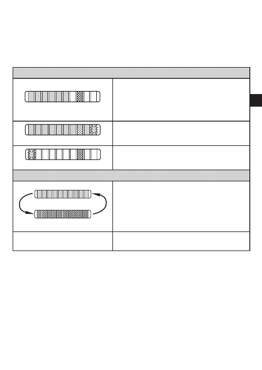
9 Operation
After every power on all LEDs light and go out again step by step (during this time
the output is closed if configured as normally open)� The unit is then ready for
operation�
In case of power failure or interruption all settings remain�
Operating indicators
Green LED bar: Current flow within the representa-
tion range�
Indication of the switch point (SP):
- LED orange: output closed�
- LED red: output open�
LED 9 flashes: current flow above the
representation range�
LED 0 flashes: current flow far below the represen-
tation range�
Interference indicator
Short circuit at the switching output:
The operating indicator and red LEDs light
alternately�
If the short circuit has been rectified, the unit im-
mediately passes into the normal operating state�
The current operating state is displayed�
Display OFF
(no LED lights):
Operating voltage too low (< 19 V) or failed�
Ensure a correct voltage supply�
10 Maintenance
Recommended maintenance:
► Check the sensor tip for build-up from time to time�
► Clean it using a soft cloth� Stubborn build-up (e�g� lime) can be removed using
a common vinegar cleaning agent�
12
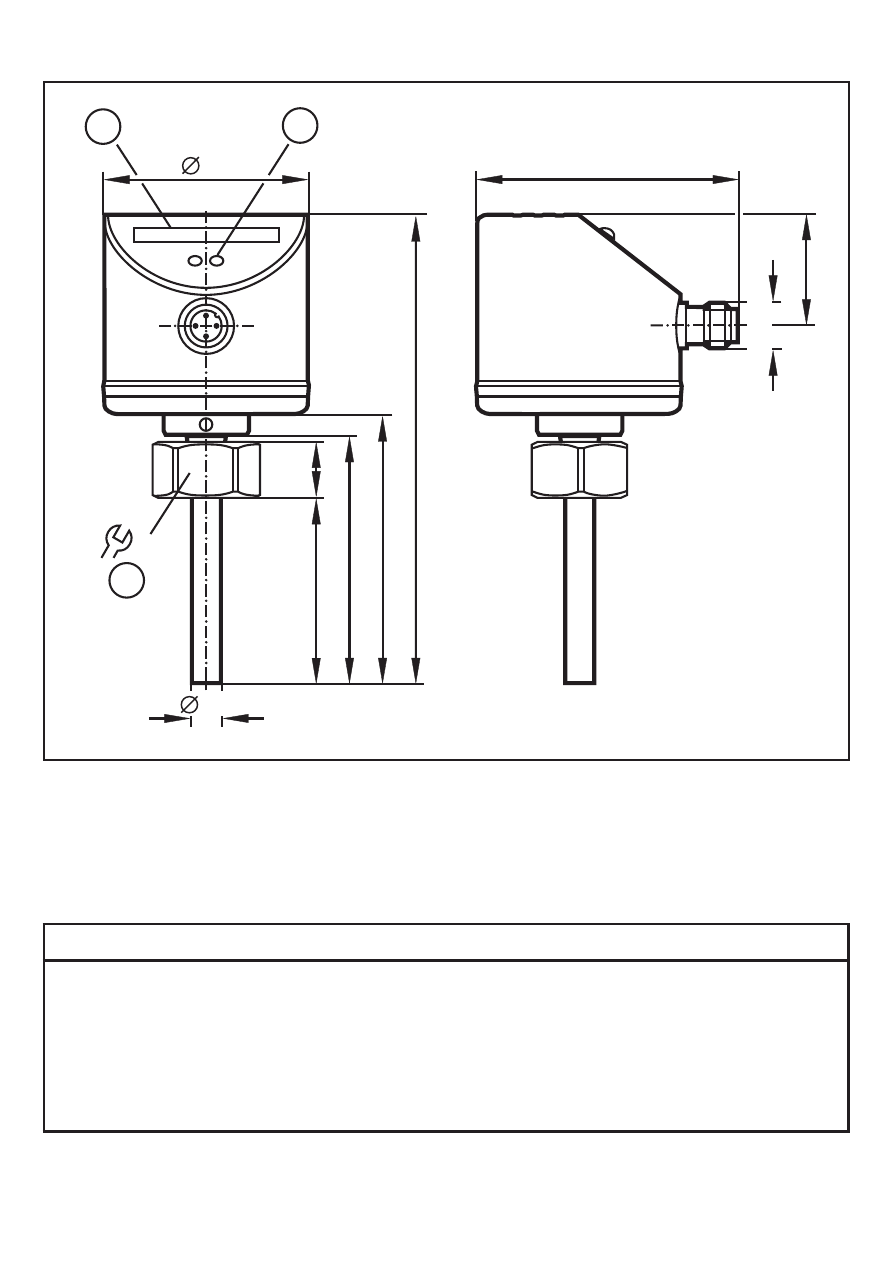
11 Scale drawing
22
1
2
113
60
65
14
8,2
45
50
27
63
M
12
x1
3
1: LED bar display
2: set button
3: tightening torque 25 Nm
12 Technical data
Application area ����������������������������������������������������������������������������������������Liquids and gases
Operating voltage [V] ����������������������������������������������������������������������������������������19 ��� 36 DC
1)
Current rating [mA] ����������������������������������������������������������������������������������������������������������250
Short-circuit protection, pulsed; reverse polarity / overload protection
Voltage drop [V] �������������������������������������������������������������������������������������������������������������< 2�5
Current consumption [mA] ���������������������������������������������������������������������������������������������< 60
Power-on delay time [s] ���������������������������������������������������������������������� 10, optically indicated

13
UK
Liquids
Medium temperature [°C] .................................................................................... -25 ... +80
Setting range [cm/s]..................................................................................................3 ... 300
Greatest sensitivity [cm/s] ..........................................................................................3...100
Temperature gradient [K/min] .........................................................................................300
Gases
Medium temperature [°C] .................................................................................... -25 ... +80
Setting range [cm/s]............................................................................................200 ... 3000
Greatest sensitivity [cm/s].....................................................................................200 ... 800
Switch point accuracy [cm/s] ................................................................................± 2...± 10
2)
Hysteresis [cm/s] ..........................................................................................................2...5
2)
Repeatability [cm/s] ......................................................................................................1...5
2)
Temperature drift [cm/s x 1/K].........................................................................................0.1
3)
Response time [s] .......................................................................................................1 ... 10
Pressure resistance [bar].................................................................................................300
Operating temperature [°C] .................................................................................. -25 ... +80
Protection rating ........................................................................................................... IP 67
Protection class ..................................................................................................................III
Shock resistance [g] .............................................................. 50 (DIN / IEC 68-2-27, 11 ms)
Vibration resistance [g] ...................................................20 (DIN / IEC 68-2-6, 55-2000 Hz)
Housing materials ......................stainless steel 316L / 1.4404; stainless steel 304 / 1.4301;
PC (Makrolon); PBT-GF 20; EPDM/X (Santoprene)
Materials (wetted parts) ........................................................... stainless steel 316L / 1.4404
O-ring: FPM 8x1.5 gr 80° Shore A
EMC
EN 61000-4-2 ESD: ................................................................................ 4 kV CD / 8 kV AD
EN 61000-4-3 HF radiated: ...................................................................................... 10 V/m
EN 61000-4-4 Burst: ..................................................................................................... 2 kV
EN 61000-4-6 HF conducted: ....................................................................................... 10 V
1)
to EN50178, SELV, PELV;
2)
for water; 5...100 cm/s; 25°C (factory setting)
3)
for water; 5...100 cm/s; 10...70°C
The sensor conforms to the standard EN 61000-6-2
More information at www.ifm.com
Document Outline
- 1 Safety instructions
- 2 Functions and features
- 3 Installation
- 4 Electrical connection
- 5 Operating and display elements
- 6 Set-up and settings for water
- 7 Additional settings (optional)
- 8 Error during adjustment
- 9 Operation
- 10 Maintenance
- 11 Scale drawing
- 12 Technical data
Wyszukiwarka
Podobne podstrony:
czujnik przeplywu
IFM czujniki zastosowanie
Czujniki i przetworniki przepływu
IFM czujniki zastosowanie
Czujniki i przetworniki przepływu
Czujniki obciążenia silnika Przepływomierze powietrza
SWOBODA PRZEPŁYWU UE
Układy wodiociągowe ze zb przepł końcowym i hydroforem
Swobodny przepływ kapitału w UE
Rachunek Przeplywow pienieznych
02 czujniki, systematyka, zastosowania
Cytometria przepływowa
przepływ w szczelinie
czujniki2
POMIAR NATĘŻENIA PRZEPŁYWU W PRZEWODZIE POD CIŚNIENIEM I KORYCIE OTWARTYM
Czujniki temperatury cieczy chłodzącej
5 Czujniki Podrecznik PL
więcej podobnych podstron