www.BobsPlans.com
6
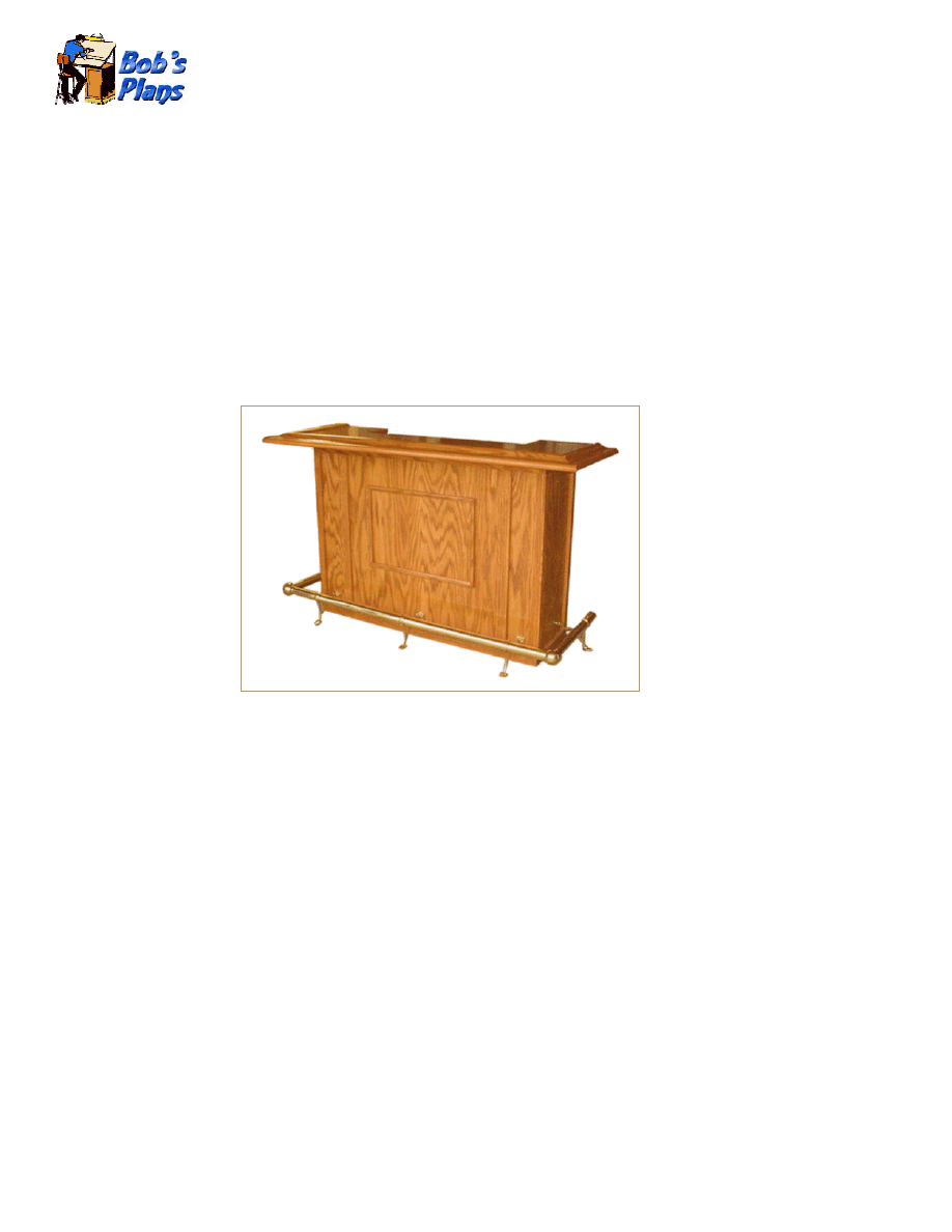
Foot
Home Bar
Home Bar Plans
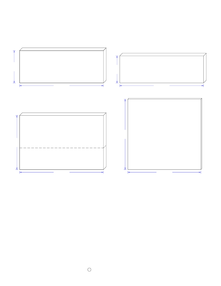
Entertain your friends in style with this beautiful oak bar. The top is 6 ft. long and 24” deep. The overall
height about 42”. The classic design features solid oak armrest molding, solid brass foot rail, a
convenient work shelf in the rear, three drawers, and two sliding wine racks. The cabinet is made of ¾”
oak veneered plywood. The trim and drawer fronts, from ¾” solid oak.
The extensive use of pocket holes makes the assembly of this project easy and intuitive. If you have
never used pocket holes in your woodworking projects, you’ll wonder how you ever got by without
them. Pocket hole joints are extremely strong and there is no measuring. You simply drill the pocket
holes in one of the work pieces to be joined, (the exact location is not critical), clamp the pieces together
and insert the screws. Since the screws remain in the joint, they serve as both a dowel and a permanent
clamp.
Copyright
© 2005 by Robert E. Reedy
All rights reserved

Table of Contents
Part 1 - Dimensions
Materials List – Cabinet ................................................................. 1
Front Panel .................................................................................... 2
Side Panel & Vertical Divider ...................................................... 3
Kick Panel, Shelf, & Cleats ........................................................... 4
Front Trim ...................................................................................... 5
Side Trim ....................................................................................... 6
Rear Trim ....................................................................................... 7
Rear Trim Arrangement ................................................................. 8
Materials List – Brass Foot Rail .................................................... 9
Materials List – Top & Arm Rest Dimensions ............................ 10
Bar Top .........................................................................................11
Bar Top Rear Trim.........................................................................12
Risers & Soffit ..............................................................................13
Materials List – Drawers & Wine Racks ......................................14
Drawer Box Sides, Fronts, & Backs ..............................................15
Drawer Fronts & Bottoms ............................................................16
Wine Racks ...................................................................................17

Table of Contents
Part 2 - Assembly Instructions
Attach Drawer Slides ................................................................... 18
Attach Wine Rack Slides - Assemble Bottom ........................... 19
Attach Vertical Dividers & Kick Panel ...................................... 20
Attach Side Panels and Work Shelf ..............................................21
Assemble Front & Side Panels .....................................................22
Attach Front and Side Trim ......................................................... 23
Install Upper Horizontal Trim ..................................................... 24
Arrangement of Rear Trim .......................................................... 25
Install Brackets & Measure Side Rail Length ............................. 26
Measure Front Rail Length - Assemble Rails .............................. 27
Assemble Armrest Molding ......................................................... 28
Drill Pocket Holes in the Top ...................................................... 29
Attach Rear Trim to the Top ........................................................ 30
Attach Risers to the Top .............................................................. 31
Attach Top to Molding & End Soffit ........................................... 32
Attach Center Soffit ..................................................................... 33
Assemble Drawers ....................................................................... 34
Assemble Wine Racks ................................................................. 35
Cutout Suggestions (1) .................................................................36
Cutout Suggestions (2) .................................................................37
Cutout Suggestions (3) .................................................................38
Materials You Will Need
Two Sheets of ¾” Oak Veneer Plywood - See Cutout Suggestions (1)
One Sheet of ½” Oak Veneer Plywood - See Cutout Suggestions (2)
One fourth Sheet of ¼” Hardboard - See Cutout Suggestions (2)
Four 5 ½” by 8’ by ¾” Oak Boards
One 6 ½” by 8’ by ¾” Oak Board
10 Ft. of Oak Armrest Molding - Rockler Item # 42768 & 42777 Link:
http://www.rockler.com/findit.cfm?page=5762&sid=AF913
10 Ft. Brass Foot Rail Kit - Rockler Item # 57684 Link:
http://www.rockler.com/findit.cfm?page=907&sid=AF913
Five Sets of 14” Drawer Slides (May be at local hardware stores) Rockler Item # 34835 Link:
http://www.rockler.com/ecom7/product_details.cfm?offerings_id=1507&sid=AF913
Three Drawer Pulls (Available at Rockler or local hardware stores)
Pocket Hole Face Frame Screws (One or two pounds)
1” Flathead screws (About 50)
1” Finishing Nails (Less than a pound)
1 ½” Finishing Nails (Less than a pound)
7 Small Angle Brackets (Available at local hardware stores)
Tools You Will Need
Table Saw
Drill
Pocket Hole Jig
Sander
Hand Tools
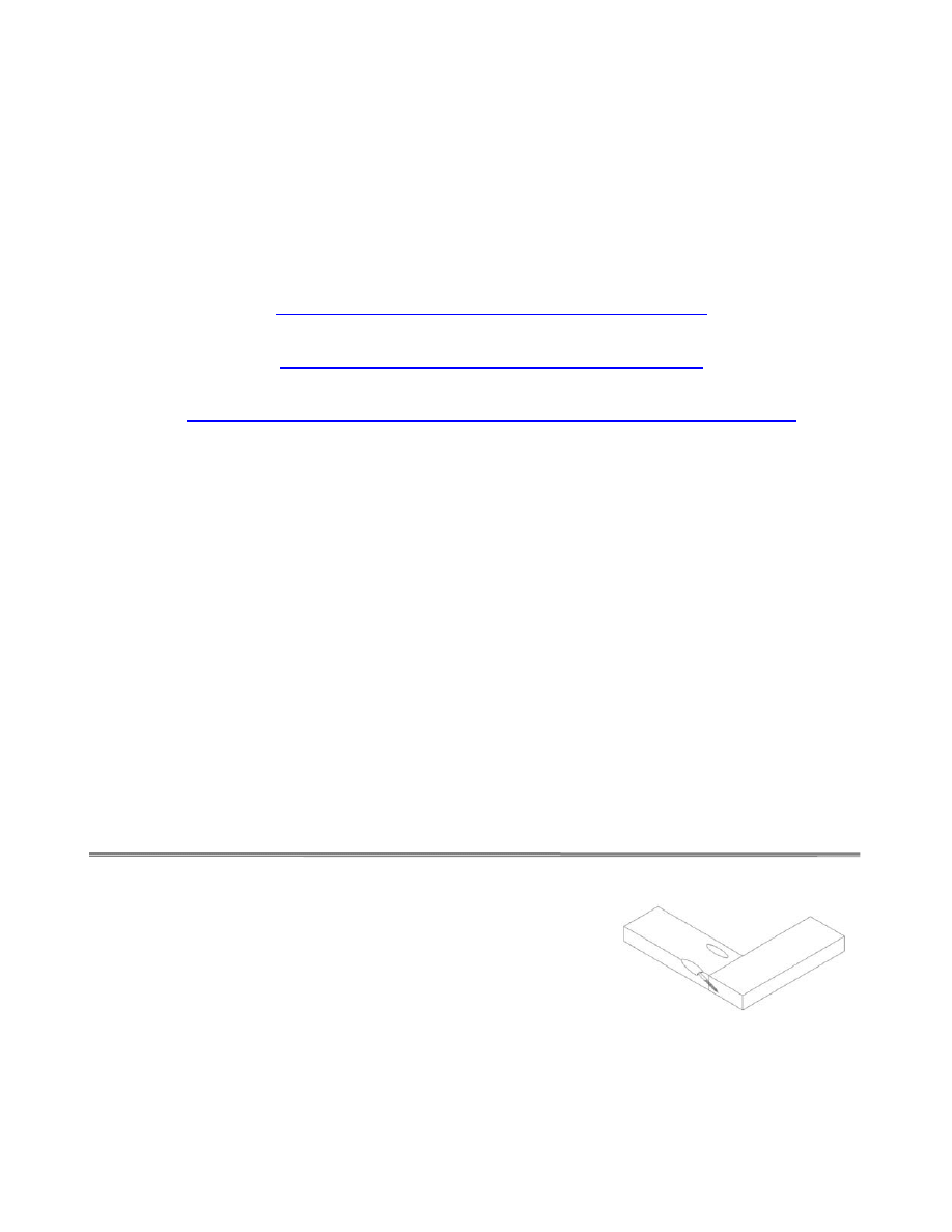
Pockets holes are about the easiest way I know to join wood. You
simply use the jig to drill a pocket hole in one work piece, apply
some glue, secure the pieces with a clamp, then insert the screw as
shown in the Illustration.
If you have not experienced the ease and efficiency of pocket hole
joinery yet, maybe you’ll be ready to try it after looking through
these assembly drawings and instructions. You can get a simple
pocket hole jig kit with a step drill and stop collar for less than
$20 and a really nice one for less than $150. Note: A drill press pocket hole jig isn’t suitable for the
plywood panels required for this project. A selection of suitable pocket hole jigs are pictured on the
last page of this document.
Spoke Wheel
6 Foot
Heart Wheel
Wheelbarrow Planter
Traditional Picnic Table
Wheelbarrow Planter
Portable Router Table
Table Saw Jig/Sled
Drill Press table
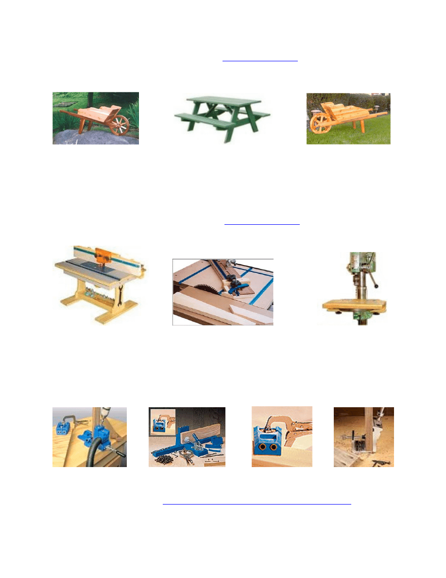
Pocket Hole Jigs from Rockler Woodworking & Hardware
New! Kreg ® K3 System
Kreg ® K2000
Kreg ® Rocket Jig
Pock’It Jig
www.rockler.com/CategoryView.cfm?Cat_ID=227&sid=AF913
Copyright
2005 by Robert E Reedy, Vandalia, Ohio

Cabinet Materials List
Page 1
Please Note! The dimensions given are based on using 3/4" thick plywood. However, much of the
plywood on the market today is actually a metric size and is slightly less than 3/4" thick. This will not
affect most of the dimensions, however, you will need to adjust the dimensions of the rear trim
accordingly if your plywood is less than 3/4" thick.
Qty
Size
Material
Item Name
2
6 1/2" X 41 1/8"
3/4" Oak Plywood
Left and Right Front Panels
1
41" X 41 1/8"
3/4" Oak Plywood
Center Front Panel
2
14" X 41 1/8"
3/4" Oak Plywood
Cabinet Sides
2
14" X 23 1/2"
3/4" Oak Plywood
Vertical Dividers
2
14" X 52 1/2"
3/4" Oak Plywood
Top Work Shelf and Bottom
1
5" X 52 1/2"
3/4" Oak Plywood
Kick Panel
1
16" X 14"
3/4" Oak Plywood
Small Shelf
15
14” X 2”
3/4" Oak Plywood
Cleats
2
19" X 2"
3/4" Oak Plywood
Front Cleats
2
2" X 55 1/2"
3/4" Solid Oak
Top and Bottom Trim (Front)
2
2 ½” X 36”
3/4" Solid Oak
Fluted Trim (Front)
4
1 1/2" X 36"
3/4" Solid Oak
Corner Trim
2
3/4" X 36"
3/4" Solid Oak
Side Corner Trim (Front)
4
2" X 16 1/4"
3/4" Solid Oak
Top and Bottom Trim (Side)
2
1" X 26"
3/4" Solid Oak
Decorative Frame (Top and Bottom)
2
1" X 18"
3/4" Solid Oak
Decorative Frame (Sides)
1
2" X 51"
3/4" Solid Oak
Bottom Horizontal Trim (Back)
1
3 1/4" X 51"
3/4" Solid Oak
Top Horizontal Trim (Back)
2
1 1/2" X 21"
3/4" Solid Oak
Vertical Divider Trim (Back)
2
1 1/2" X 40"
3/4" Solid Oak
Vertical Corner Trim (Back)
2
1 1/2" X 14 1/2"
3/4" Solid Oak
Drawer Divider Trim (Back)
Copyright
© 2005 by Robert E Reedy, Vandalia, Ohio
Copyright
2005 by Robert E. Reedy, Vandalia, Ohio
C
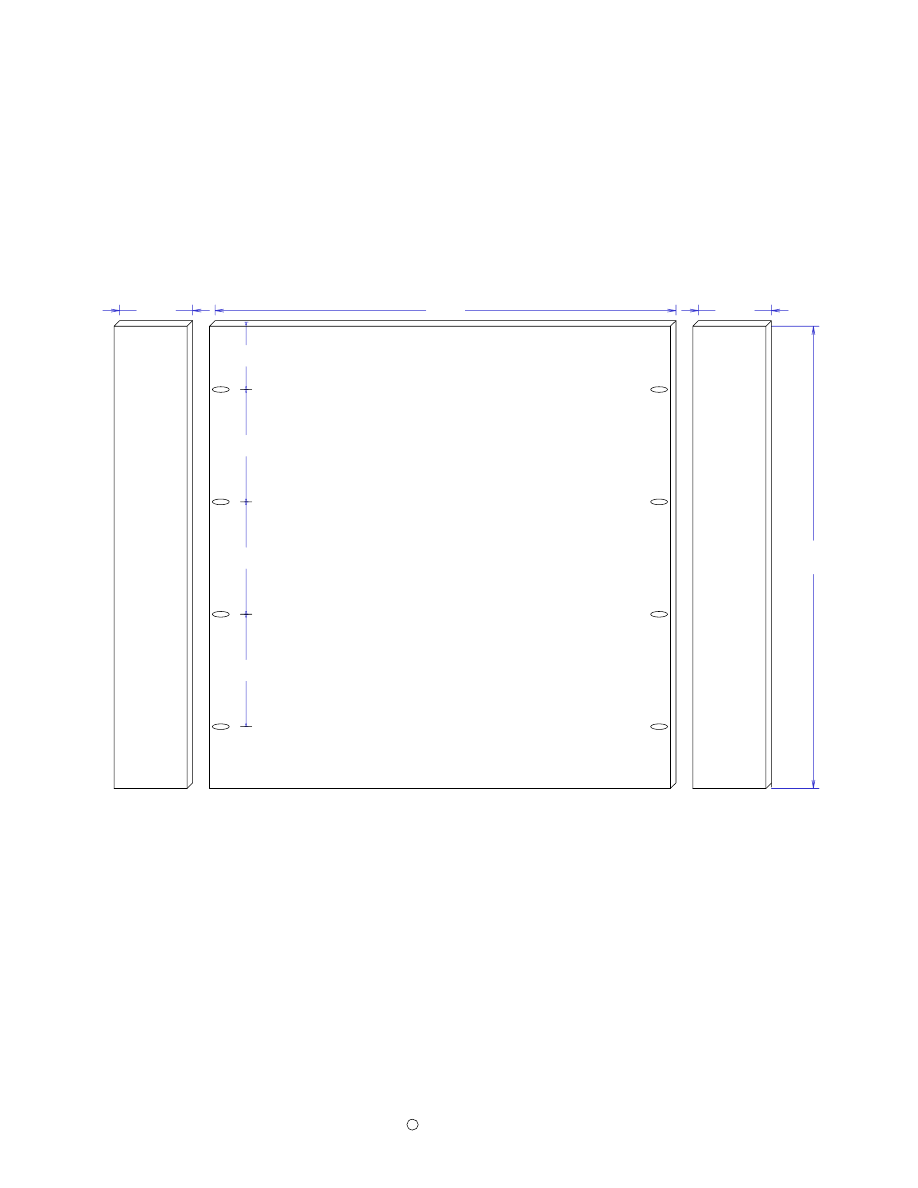
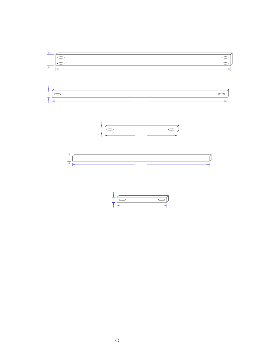
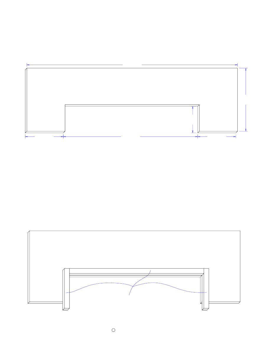
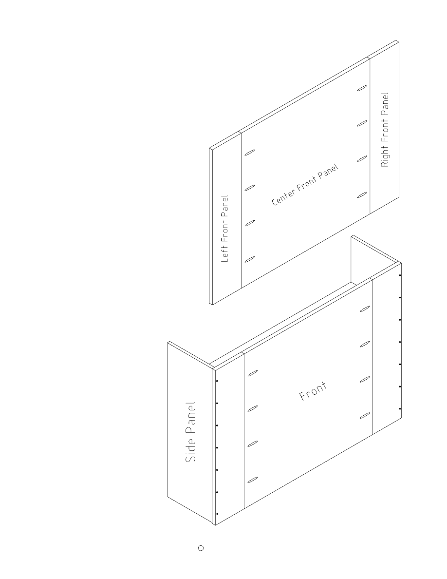
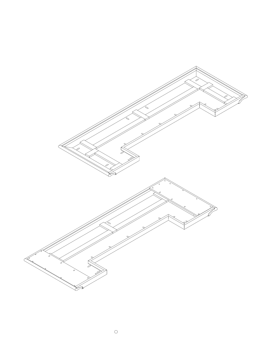
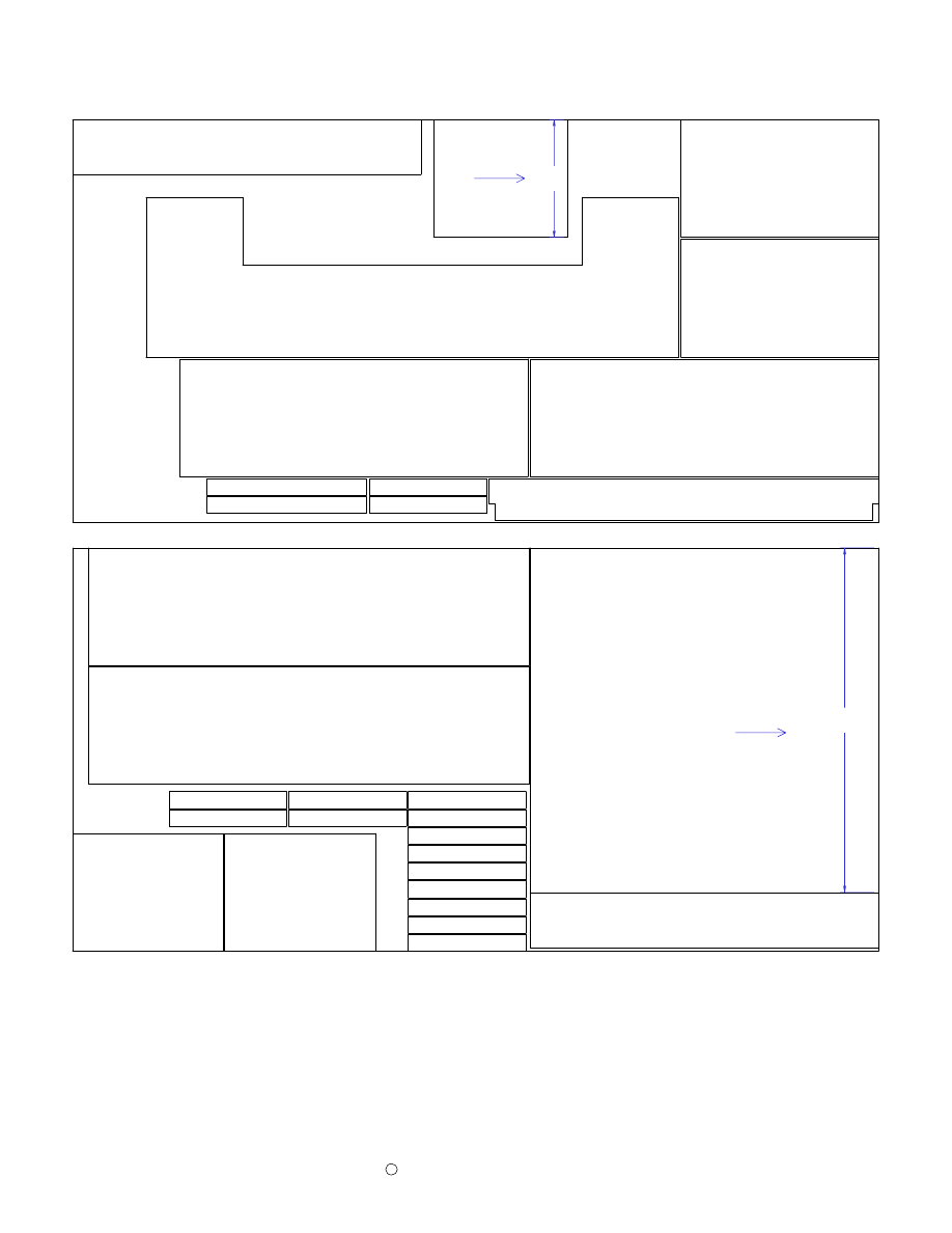
Front Panel Dimensions
Page 2
Drill pocket holes on the front sides of the center panel as shown above. These
pocket holes are used to attach the three front panels together. The pocket holes will
be covered with the trim later.
41 1/8"
R
ig
h
t
F
ro
n
t
P
a
n
e
l
41"
6"
10"
10"
10"
Center Front Panel
6 1/2"
L
e
ft
F
ro
n
t
P
a
n
e
l
6 1/2"
Copyright
2005 by Robert E. Reedy, Vandalia, Ohio
C
Side Panel & Vertical Divider
14"
23 1/2"
Dividers
(2 Required)
Cut two side panels 14" wide and 41 1/2"
high from 3/4 inch oak veneered
plywood. Cut two vertical divider panels
14" wide and 23 1/2" high from the same
material.
Cut two pieces of 3/4" oak veneered plywood 52 1/2" wide by 14" deep. One is for
the cabinet bottom and the other for the main work shelf.
Workshelf/Bottom
14"
52 1/2"
(2 Required)
free picnic table plans
Page 3
41 1/8"
14"
(2 Required)
Cabinet
Sides
Copyright
2005 by Robert E. Reedy, Vandalia, Ohio
C
Kick Panel, Shelf, & Cleats
Page 4
3"
52 1/2"
Kick Panel
5"
3/4"
Cut the Kick Panel 52 1/2" long by 5" wide from 3/4" oak plywood. Cut the notches
and drill pocket holes as shown. The location of the pocket holes is not critical.
Small Shelf
14"
16"
Cut the small shelf 16" wide by
14" deep from 3/4" oak veneered
plywood.
2"
14"
Cut fifteen cleats 14" long by 2" wide from 3/4"
oak veneered plywood. Seven of these cleats
require pocket holes. All fifteen cleats require
three 3/16" diameter holes for mounting screws.
The screw holes need to be countersunk. The
pocket holes should be about 1 1/2" from each
end and one in the center. The screw holes 1/2"
from the pocket holes as pictured.
The reason only seven require pocket holes is that five of these cleats will be used
only for drawer slide mounts for the three drawers and do not require pocket holes.
This will be illustrated in the assembly instructions
2"
19"
Front Cleats
Cut two cleats 19" long by 2" wide from 3/4"
oak veneered plywood. Drill pocket holes and
mounting screw holes as for the 14" cleats.
These are for securing the workshelf and bottom
to the cabinet front
Copyright
2005 by Robert E. Reedy, Vandalia, Ohio
C
Front Trim
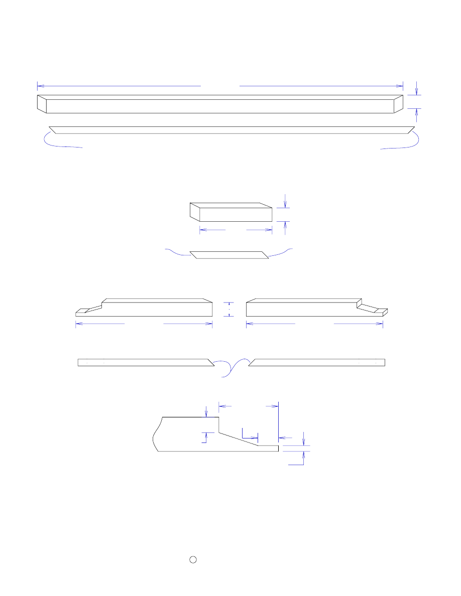
Page 5
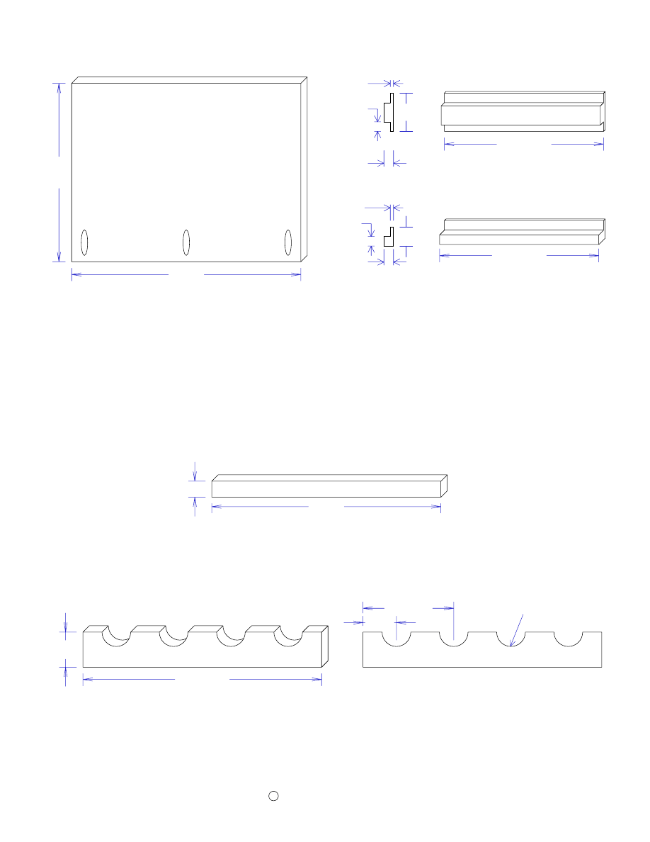
Cut two pieces of 3/4" oak 36" long by 2 1/2" wide for the fluted front trim. These pieces
will cover the joint and pocket holes that are used to join the three front panels together.
The flutes are not necessary but if you have a router table, I think they are worth the extra
trouble.
Use your router with a 1/2" core box bit to cut the flutes. The center flutes should be about
4" from each end and the edge flutes should be about 4 3/4" from each end. I recommend
using some scrap wood to practice making the flutes. You will need to use your router table
and fence for this if you have one.
"
4 3/4
"
4
5/8 "
1 1/4"
Tip: make pencil marks on your router table fence on each side of the router bit, one 4"
from the center of the bit and the other 4 3/4". Then, you can use these marks to determine
the start and stop point of the workpiece.
2 1/2"
36"
Fluted Trim
2"
55 1/2"
45° Angle
45° Angle
Front Top & Bottom Trim (2 Required)
Top View
Side Trim
Page 6
Copyright
2005 by Robert E. Reedy, Vandalia, Ohio
C
36"
1 1/2"
36"
3/4"
16 1/4"
2"
Top View
45° Angle
For the corner trim, you'll need four pieces of 3/4" oak 36" long by 1 1/2" wide.
For the front corner trim, you'll also need two pieces of 3/4" oak 36" long by 3/4" wide.
For the Top and Bottom Side trim, you'll need four pieces of 3/4" oak 16 1/4" by 2". One
end of the top and bottom trim requires a 45 degree miter cut because it must mate with the
front top and bottom trim.
Decorative Frame
26"
1"
18"
1"
End View of Molding
Cut two pieces of molding 26" long for the frame top. Cut two pieces of molding 18" long
for the frame sides. All corners must have 45 degree miters. I made the molding from 3/4"
by 1" wide oak and used a round over bit and ogee bit to give it the shape shown above. If
you don't want to go with the above shape, you could simply round over both sides, use a
beading bit, or any other design you choose.
(2 Required)
Sides
(2 Required)
Top & Bottom
CornerTrim (4 Required)
Side Corner Trim (2 Required)
Side Trim (4 Required)
Rear Trim
Page 07
Copyright
2005 by Robert E. Reedy, Vandalia, Ohio
C
51"
3 1/4"
Rear Top Horizontal Trim
2"
51"
Rear Bottom Horizontal Trim
Drawer Divider Trim (2 Required)
Please Note! The dimensions given are based on using 3/4" thick plywood. However, much
of the plywood on the market today is actually a metric size and is slightly less than 3/4"
thick. You will need to adjust the dimensions of the rear trim accordingly if your plywood
is less than 3/4" thick.
The top and bottom horizontal trim may need to be slightly longer if your plywood is less
than 3/4" thick. The vertical divider trim needs to be exactly twice the thickness of the
plywood. So, if your plywood is less than 3/4" thick, the width of these pieces will be a
little less than 1 1/2".
The pocket holes pictured on some of the pieces above are optional but you may want to
use them to assemble the trim before attaching it to the cabinet.
Vertical Divider Trim (2 Required)
21"
1 1/2"
40"
Back Corner Trim (2 Required)
1 1/2"
14 1/2"
1 1/2"
Rear Trim Arrangement
Page 8
Copyright
2005 by Robert E. Reedy, Vandalia, Ohio
C
Attach the top horizontal trim piece 10" from the top of the side trim pieces with pocket
hole screws as shown.
Attach the vertical divider trim to the top horizontal trim as shown.
Attach the bottom horizontal trim to the vertical side trim and vertical divider trim as
shown.
Attach the drawer divider trim as shown.
1.
2.
3.
4.
9"
5"
4"
Top Horizontal Trim
Drawer Divider Trim
Drawer Divider Trim
V
e
rt
ic
a
l
D
iv
id
e
r
T
ri
m
V
e
rt
ic
a
l
D
iv
id
e
r
T
ri
m
B
a
c
k
C
o
rn
e
r
T
ri
m
B
a
c
k
C
o
rn
e
r
T
ri
m
Bottom Horizontal Trim
21"
10"
14 1/2"
14 1/2"
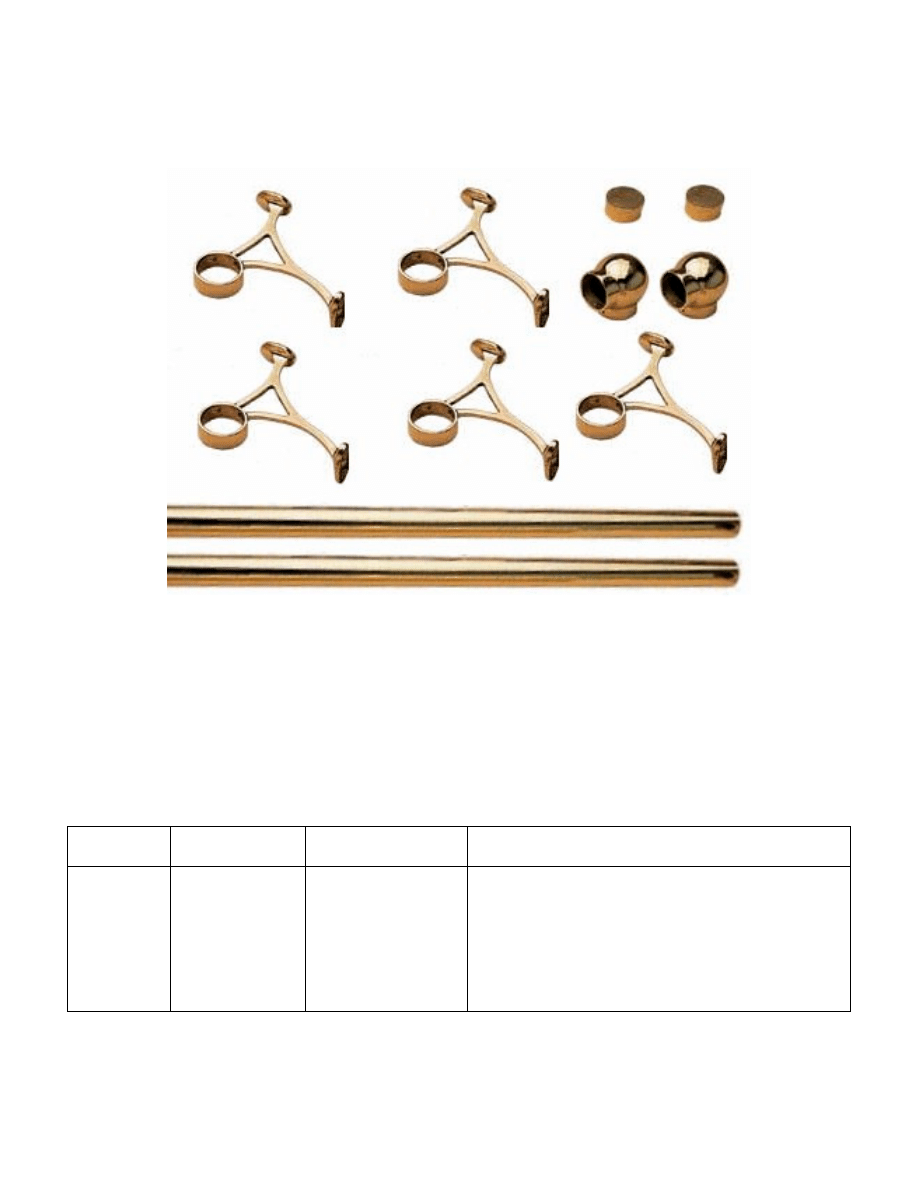
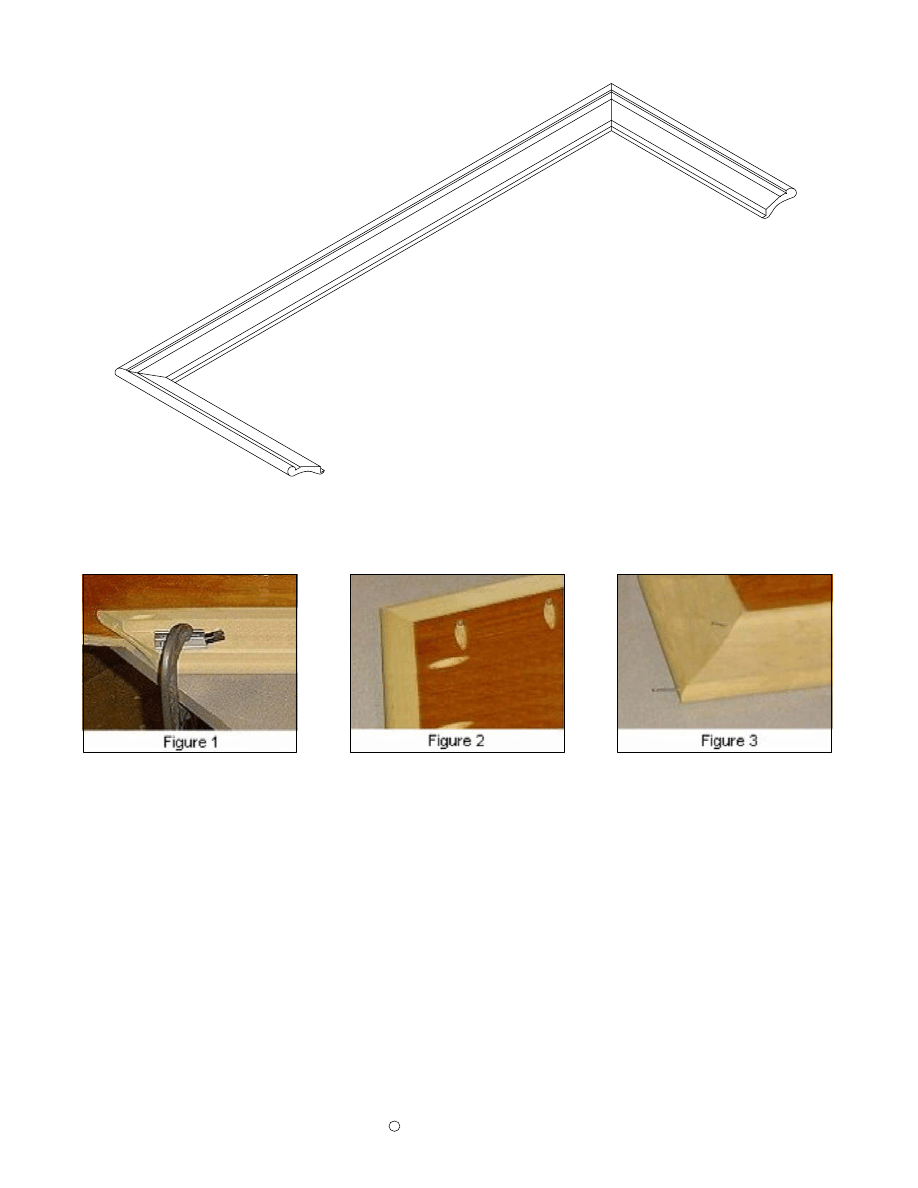
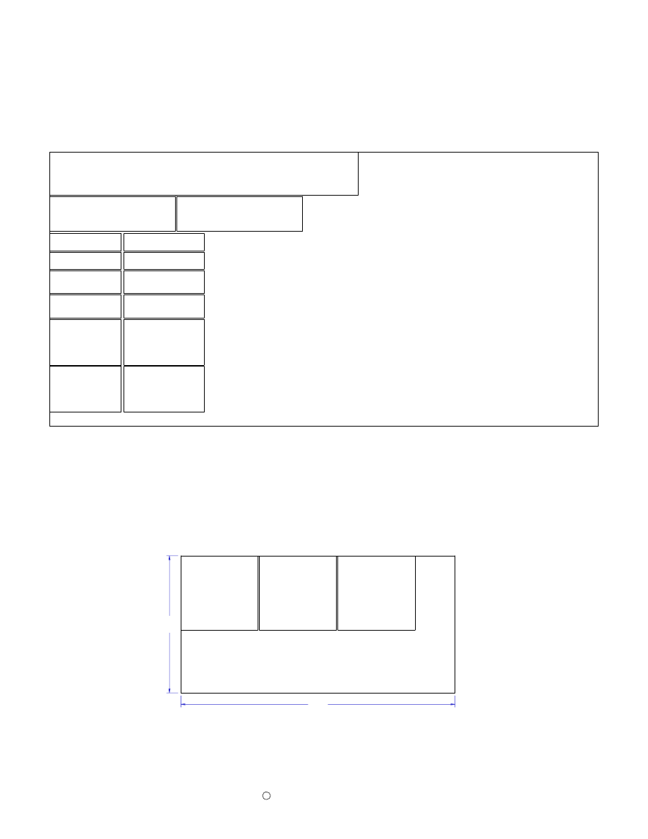
Brass Foot Rail Materials
Page 9
Figure 1
For the prototype bar, I purchased the 10 foot kit with 2" diameter from Rockler. The kit has everything
you need for the brass rail. A 1 1/2" diameter size is also available for a little less money. You can buy the
brass materials separately too.
Instructions for measuring the brass rail lengths are in the assembly instructions.
Qty
Size
Material
Item Name
1
2" Diameter
Brass Rail Kit
10 Ft Brass Rail Kit Rockler Item Number 57684
1 each - 6' Brass Railing (N) see image below
1 each - 4' Brass Railing (Not sold separately)
5 each - Brass Combination Brackets
2 each - Brass Rail End Caps
2 each - Brass Rail Elbows
Copyright
2005 by Robert E Reedy, Vandalia, Ohio
Materials List for the Top & Armrest Molding Dimensions
Page 10
1
2
6 Ft
2 Ft
Rockler item number 42768
Rockler item number 42777
Oak Arm Rest Molding
Oak Arm Rest Molding
1
63 1/2" X 19"
Countertop
3/4" Oak Plywood
1
40 1/2" X 1 1/2"
Countertop cutout trim
3/4" Solid Oak
2
8" X 1 1/2"
Countertop cutout trim
3/4" Solid Oak
2
15 1/8"X 1 1/2"
Countertop cutout trim
3/4" Solid Oak
4
4 3/4" X 2"
Countertop risers
5/8" Pine
3
4 1/4" X 2"
Countertop risers
5/8" Pine
2
10 3/4" X 2"
Countertop risers
5/8" Pine
2
25" X 2"
Countertop risers
5/8" Pine
2
7 3/4" X 22"
End soffit
1/2" Oak Plywood
1
54" X 7 1/4"
Center soffit
1/2" Oak Plywood
72"
24"
24"
45° Angle
45° Angle
45° Angle
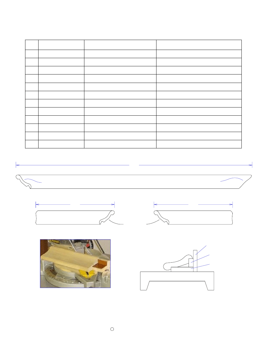
Front Armrest molding
Right armrest molding
Left armrest molding
The illustration above shows how to cut the 45° angles with your miter saw. The 1 3/8" by
3/4" and the 3 5/8" by 3/4" spacer strips hold the molding in the same position it will be
installed on the bar top. This is an easy way to make a compound miter cut.
Copyright
2005 by Robert E. Reedy, Vandalia, Ohio
C
Miter Saw Backstop
1 3/8" by 3/4"
3 5/8" by 3/4"
Miter Saw Base
Size
Item Name
Qty
Material
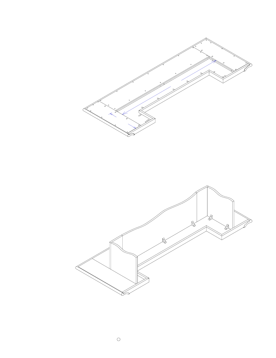
Bar Top
Page 11
Copyright
2005 by Robert E. Reedy, Vandalia, Ohio
C
Note: The length and width of the Bar Top depend on the exact inside dimensions of the
assembled armrest molding. I recommend you assemble the armrest molding first, then
measure the inside opening to determine the exact length and width of the Bar Top.
The cuts for the center opening must be perfectly straight and smooth so the trim can fit
flush. I recommend cutting the opening so 1/16" to 1/8" of material still needs to be
removed and using your router to true the edges to the exact dimensions.
Attach three perfectly straight pieces of 3/4" thick wood along the edges of the cutout to
serve as router guides as shown below.
Be sure to attach these strips to the bottom side so
you don't have screw holes showing on the top.
Use a straight router bit with a bearing on
the end and a 1" cutting depth. Turn the workpiece over and carefully run the router along
the edge guides with the bit bearing following the edge guides.
After truing up the edges with your router, the inside corners will need to be carefully
trimed with a file.
Bar Top
Temporary router guides
Bottom Side
63 1/2"
19"
8"
11 1/2"
11 1/2"
40 1/2"
Bar Top
Bar Top Rear Trim
Copyright
C
2005 by Robert E. Reedy, Vandalia, Ohio
Top View
Top View
45° Angle
Page 12
45° Angle
Top View
45° Angle
Rear Countertop Trim (Ledt Side)
Rear Countertop Trim (Right Side)
15 1/8"
15 1/8"
1 1/2"
Countertop trim pieces are all cut from 1 1/2" by 3/4" solid oak.
40 1/2"
1 1/2"
Center Cutout Trim
Top View
45° Angle
45° Angle
Side Cutout Trim (Two Required)
8"
1 1/2"
2 7/8"
3/4"
1"
Detail View
1/4"
25"
2"
Riser
The soffit pieces are used as trim between the armrest molding and the cabinet panels.
These pieces also serve to support the outer edges of the molding.
The soffit is made from 1/2" plywood.
The dimensionss given in the drawings above should
be considered guidelines only. As with the risers, wait until you're ready to assemble the
Bar Top before cutting the soffit. Then you can tell exactly what the dimensions should be.
All the risers are 5/8" thick and 2" wide.
Since armrest dimensions may vary, the lengths
given in the drawings above should be considered guidelines only. Wait until you're ready
to assemble the Bar Top before cutting the risers. Then you can tell exactly how long they
need to be.
Risers & Soffit
Page 13
2"
Riser
10 3/4"
Riser
4 3/4"
Riser
4 1/4"
Center Soffit
7 1/4"
54"
7 3/4"
22"
End Soffit (2 Required)
Copyright
C
2005 by Robert E. Reedy, Vandalia, Ohio

Materials List - Drawers & Wine Racks
Page 14
Drawers Materials List
Qty
Size
Material
Item Name
2
12 1/2" X 3"
1/2" Oak Plywood
Top Drawer Box Front & Back
2
12 1/2" X 4"
1/2" Oak Plywood
Middle Drawer Box Front & Back
2
12 1/2" X 8"
1/2" Oak Plywood
Lower Drawer Box Front & Back
2
14" X 3"
1/2" Oak Plywood
Top Drawer Box Sides
2
14" X 4"
1/2" Oak Plywood
Middle Drawer Box Sides
2
14" X 8"
1/2" Oak Plywood
Lower Drawer Box Sides
3
13 1/2" X 13"
1/4" Hardboard
Drawer Bottoms
1
15 1/2" X 5"
3/4" Solid Oak
Top Drawer Front
1
15 1/2" X 6"
3/4" Solid Oak
Middle Drawer Front
1
15 1/2" X 10"
3/4" Solid Oak
Lower Drawer Front
3
14"
Drawer Slide Set
Wine Rack Materials List
Note: This materials list is for two wine racks.
Qty
Size
Material
Item Name
2
18" X 14"
3/4" Oak Plywood
Wine Rack Bottom
2
18 3/4" X 2 3/4"
3/4" Solid Oak
Wine Rack Front
2
18" X 1 1/4"
3/4" Solid Oak
Wine Rack Back
6
12 1/2" X 3"
3/4" Solid Oak
Wine Rack
Center
Divider
4
12 1/2" X 1 1/2"
3/4" Solid Oak
Wine Rack Side
2
14"
Drawer Slide Set
Copyright
2005 by Robert E Reedy, Vandalia, Ohio
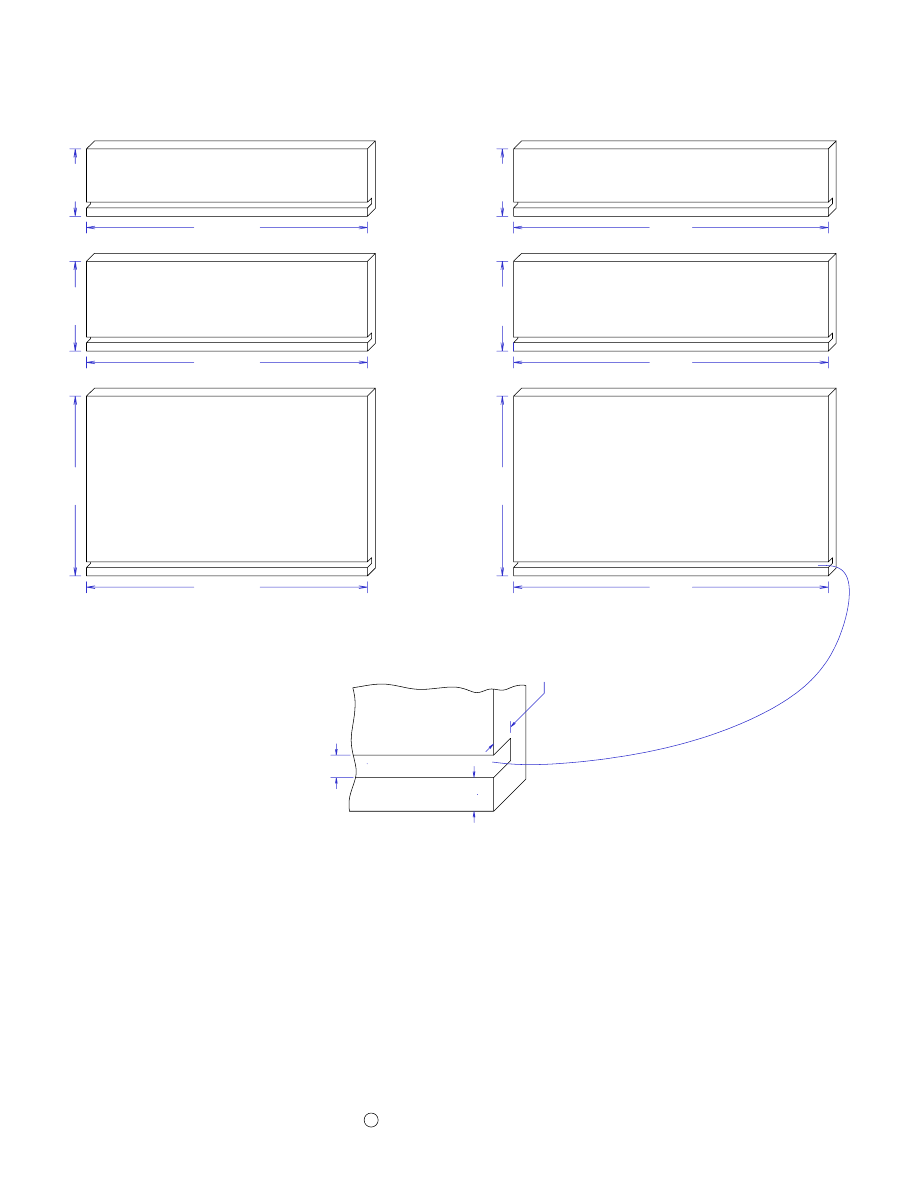
Drawer Box Sides, Fronts, and Backs
Page 15
Copyright
C
2005 by Robert E. Reedy, Vandalia, Ohio
3"
12 1/2"
Top Drawer Box Front & Back
(2 Required)
3"
14"
Top Drawer Box Sides
(2 Required)
Middle Drawer Box Front & Back
(2 Required)
4"
12 1/2"
4"
14"
Middle Drawer Box Sides
(2 Required)
Lower Drawer Box Front & Back
(2 Required)
8"
12 1/2"
8"
14"
Lower Drawer Box Sides
(2 Required)
Drawer boxes are made of 1/2" plywood
3/8"
Slot detail
1/4"
About
1/4"
Slightly over
If your plywood is exactly 1/2" thick, the above dimensions will produce a finished drawer
width of 13 1/2". This leaves 1/2" on each side for the drawer slides. If your plywood is not
exactly 1/2" thick, you will need to adjust the length of fronts and backs accordingly so your
finished drawer box width is 13 1/2". The drawer box sides should still be 14".
You'll need to cut a slot just slightly more than 1/4" deep along the the bottom of each of the
drawer box sides, fronts, and backs. This slot should be 3/8" from the bottom and slightly
wider than the thickness of the bottom material.
Drawer Fronts & Bottoms
Copyright
C
2005 by Robert E. Reedy, Vandalia, Ohio
Cut the Drawer Fronts from 3/4" solid oak. You'll probably need to glue up some narrower
pieces for the bottom drawer front. The cutout diagrams show a 6" and 4" section for making
the lower Drawer Front. The fronts will be attached to the boxes and are wider and taller
than the boxes so they will overlap the rear cabinet trim. After cutting the fronts to the
correct dimensions, you'll want to put a decorative edge along the edges with your router. I
used an ogee bit on the prototype but it's all a matter of taste.
You'll need three drawer bottoms. These are all the same size. You can use 1/4" thick
hardboard or 1/4" thick plywood as you prefer.
Drawer fronts are made from 3/4" solid oak.
Top Drawer Front
5"
15 1/2"
Drawer Bottoms
(3 Required)
13 1/2"
13"
Middle Drawer Front
6"
15 1/2"
Page 16
Lower Drawer Front
15 1/2"
10"
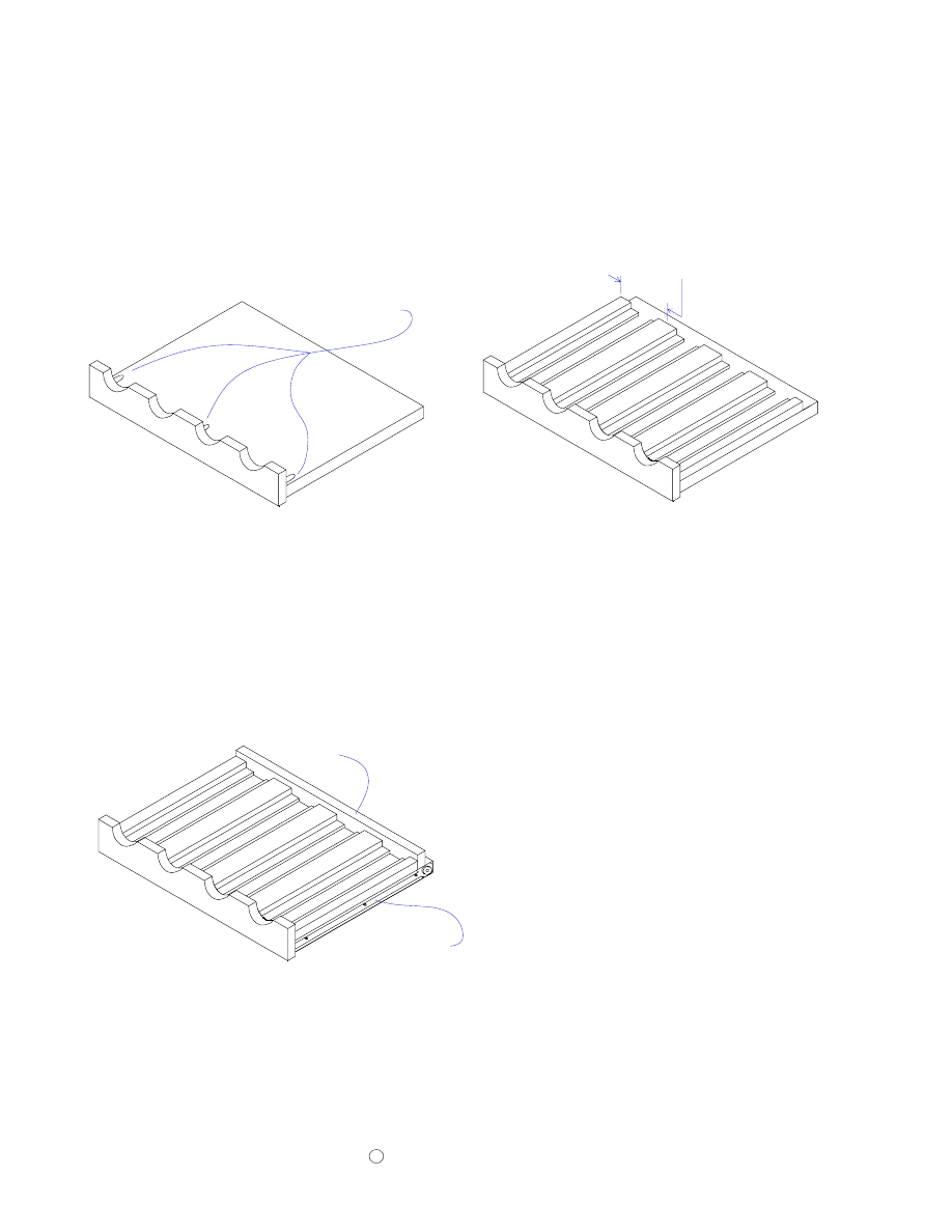
Wine Racks
Cut the wine rack bases 18" wide by 14" deep from 3/4" oak veneered plywood. Drill three
pocket holes along the front edge of the top surface as shown. One in the center and one on
each side about one inch from the edges. You'll need one base for each wine rack you add
to your bar.
Cut the dividers from 3/4" solid oak as shown above. You'll need three dividers and two
sides per wine rack.
Page 17
Wine Rack Bottom
14"
18"
Cut the wine rack backs 18" wide by 1 1/4" high from 3/4" solid oak.
You'll need one back per wine rack
18"
1 1/4"
Back
12 1/2"
Wine Rack Divider
12 1/2"
Wine Rack Side
3/4"
3/4"
1/4"
1 1/2"
3"
1/4"
3/4"
3/4"
Cut the wine rack fronts 18 3/4" wide by 2 3/4" high from 3/4" solid oak. Cut the half circle
cutouts as shown above.
2 5/8"
7 1/8"
1 1/8" Radius
2 3/4"
18 3/4"
Front
Copyright
C
2005 by Robert E. Reedy, Vandalia, Ohio
5 3/4"
16 1/4"
22 3/4"
10 1/2"
17"
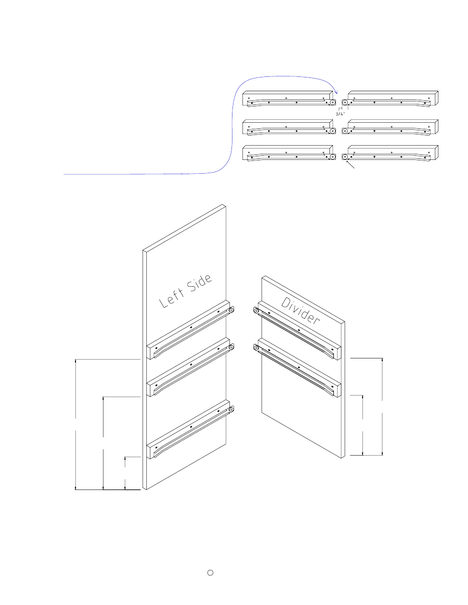
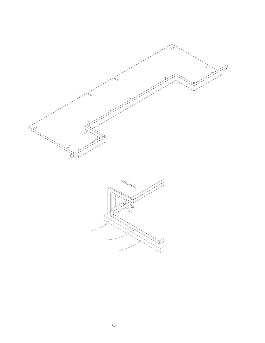
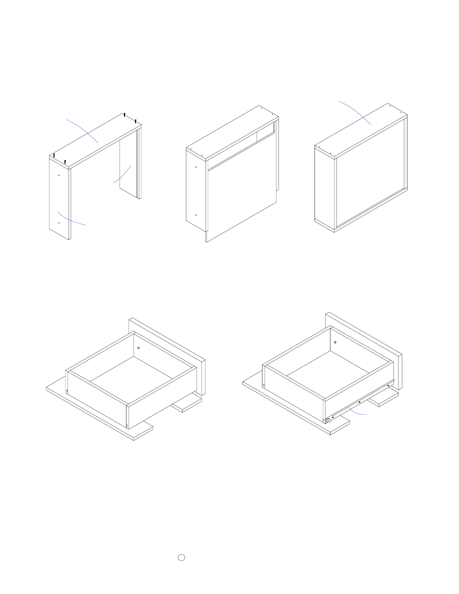
Attach three cleats with drawer slides to the left side as shown above. Attach two
cleats with drawer slides to left divider panel as shown above. Note: The bottom
cleat and drawer slide for the left divider is attached to the bottom with pocket holes
later. It will then provide a way to attach the left divider to the bottom.
Lowest part of drawer slide is
flush with bottom of wood
If you will be adding drawers to your bar, attach
the drawer slides to cleats as shown. Three must
have the roller on the right and three must have
the roller on the left. The lowest part of the
drawer slide must be flush with the bottom of
the cleat. The roller section must protrude past
the end of the cleats by 3/4" (the thickness of the
trim).
Copyright
2005 by Robert E. Reedy, Vandalia, Ohio
C
Attach Drawer Slides
Page 18
Copyright
2005 by Robert E. Reedy, Vandalia, Ohio
C
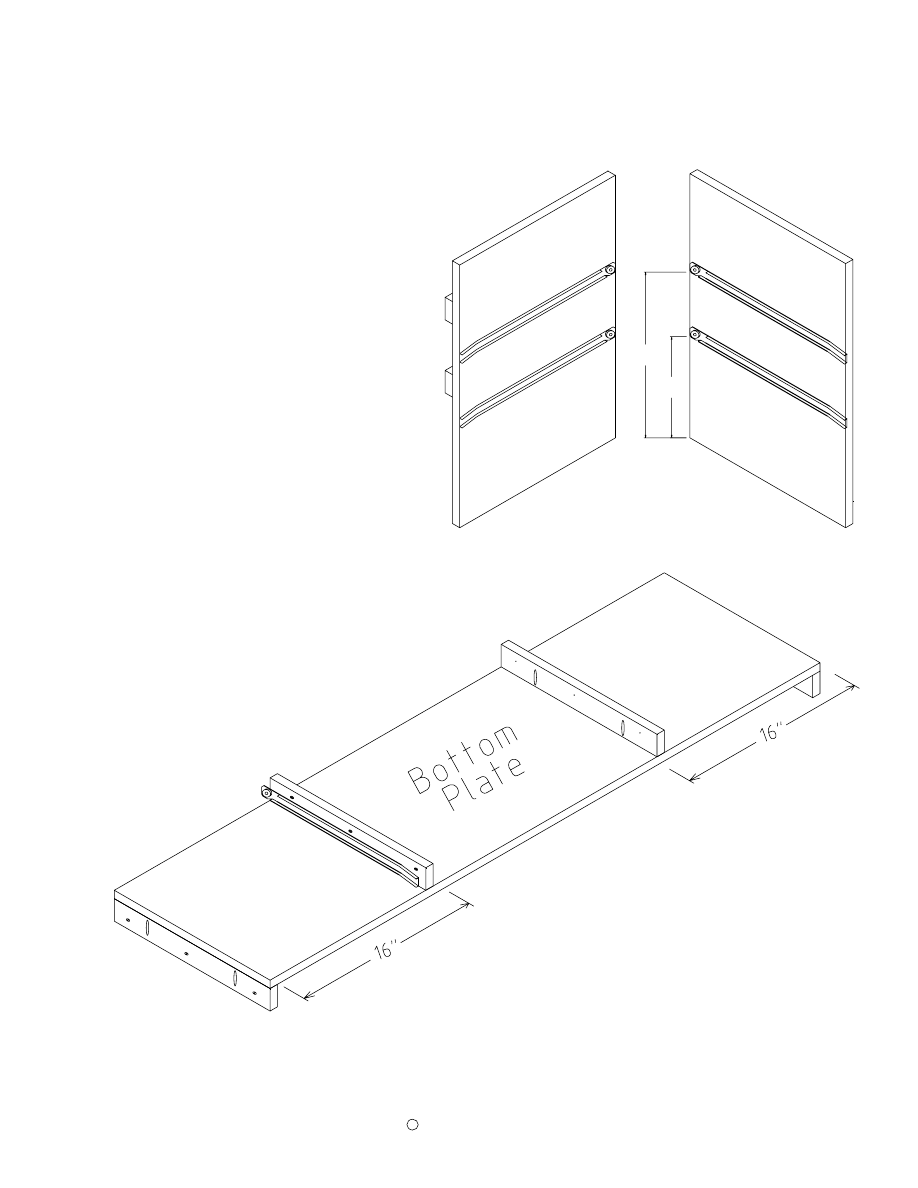
Attach Wine Rack Slides - Assemble Bottom
Page 19
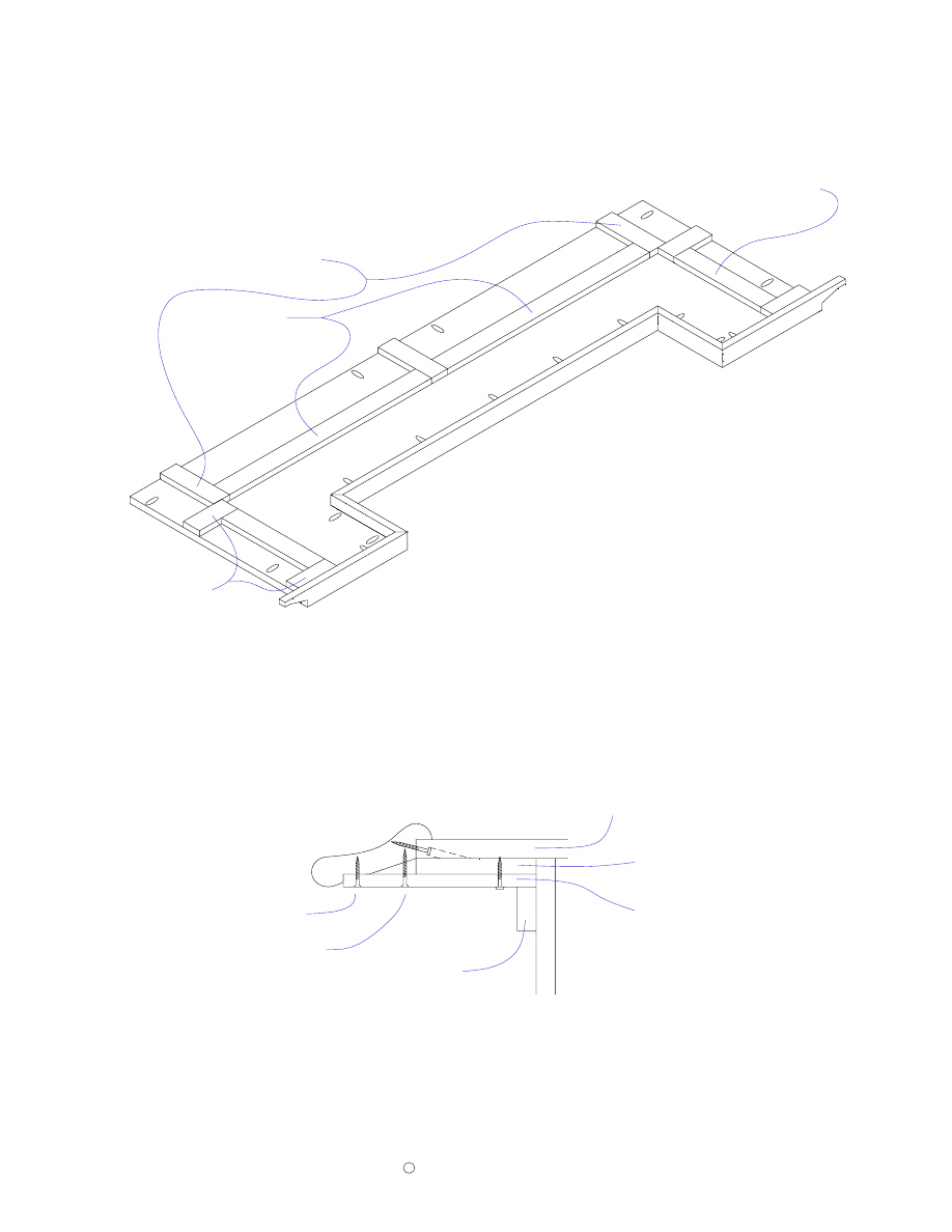
14 3/4"
9"
If you will be including wine racks, in
your bar, attach the drawer slides to the
divider panels as shown. Note: the drawer
slides for the wine racks do NOT
protrude 3/4" past the edge of the divider
panels. This is because the wine rack
fronts will be flush with the opening
while the drawer fronts will be on the
outside of the opening.
Attach two cleats to the ends of the bottom surface with pocket hole screws. These
cleats are flush to the edges of the bottom.
Attach the cleats to the top surface of the bottom plate
as shown. Pocket holes sides should be placed 16"
from the ends with pocket hole sides facing each other
as shown. (These cleats are used for mounting the
vertical panels to the bottom surface.)
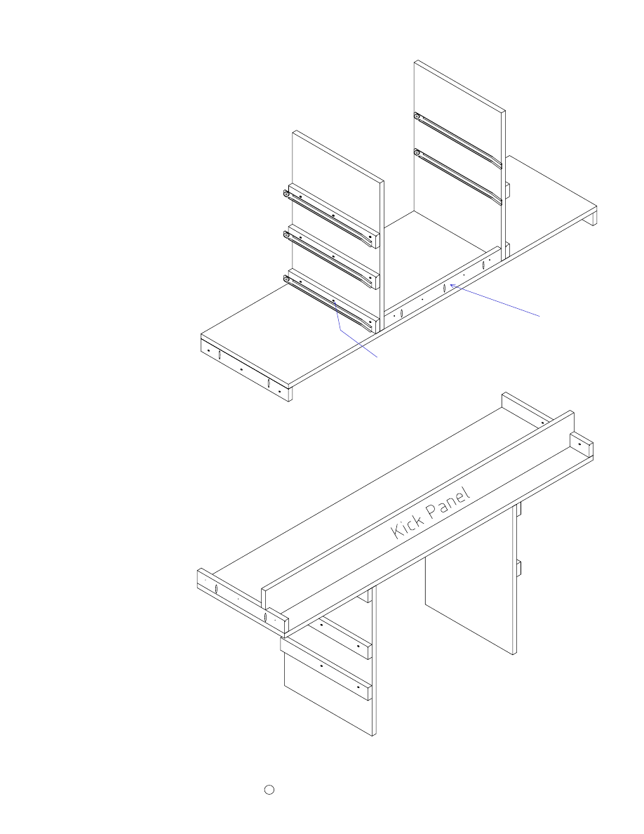
Front cleat
Attach the vertical dividers to
the cleats as shown. Attach the
front cleat between the panels as
shown with pocket hole screws.
Turn the assembly upside down
and attach the kick panel as
shown
with pocket hole screws. Note:
the pocket hole screws are on the
back side of kick panel.
Page 20
Attach Vertical Dividers & Kick Panel
Screws on this side.
Copyright
C
2005 by Robert E. Reedy, Vandalia, Ohio
Copyright
2005 by Robert E. Reedy, Vandalia, Ohio
C
Attach Side Panels and Work Shelf
Page 21
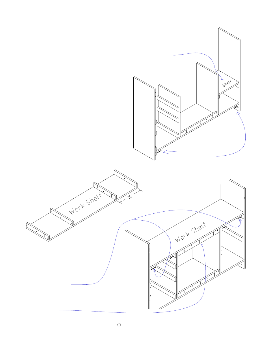
Attach the side panels to
the bottom cleats with
1 1/4" screws.
Now, attach the four cleats to the
bottom side of the work shelf with
pocket hole screws as shown. The
end cleats have pocket holes
facing out. The middle cleats have
the pocket holes facing each other.
The pocket hole side of the middle
cleats are placed 16" from the
ends of the workshelf.
Place the work shelf (with cleats
attached) on top of the vertical
dividers and secure it to the sides
and dividers with 1 1/4" screws
through the cleats.
Attach the upper front cleat
between the dividers with pocket
hole screws.
Attach the small shelf to the cleats with finishing nails.
Copyright
2005 by Robert E. Reedy, Vandalia, Ohio
C
Assemble Front & Side Panels
Page 22
Assemble the three front pieces as shown and
secure with pocket hole screws. These screws
will be covered with trim later.
Attach the front to the
cabinet assembly. Use
finishing nails to attach the
front to the sides (these
nails will be covered with
trim later.) From the back
side, use 1 1/8" screws
through the two front cleats
to attach the front to the
bottom and the workshelf.
Copyright
2005 by Robert E. Reedy, Vandalia, Ohio
C
Page 23
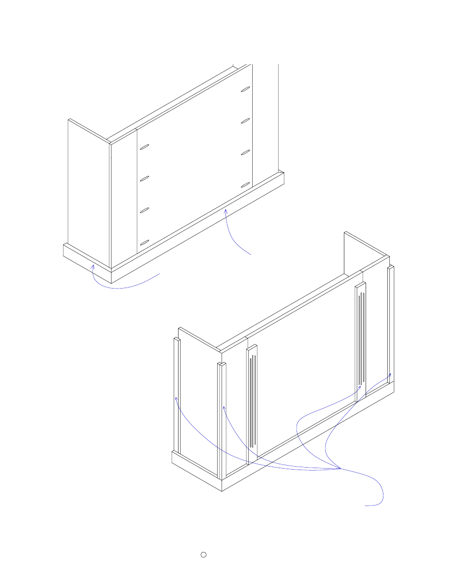
Install the vertical side and front trim pieces with finishing nails as shown.
Attach Front and Side Trim
Install the lower side and front
trim pieces along the bottom with
finishing nails as shown.
Install Upper Horizontal Trim
Page 24
Copyright
2005 by Robert E. Reedy, Vandalia, Ohio
C
Install the decorative frame molding with finishing nails as shown. Position the
molding so the frame is centered side to side and slightly higher than centered top to
bottom. The gap between the top of the frame and the top horizontal trim should be
about 1" more than the gap between the bottom of the frame and the lower
horizontal trim. If you center it top to bottom, it may actually look like it is too low
because of an optical illusion.
Install the top horizontal trim pieces with
finishing nails as shown. This should
leave a 1 1/8" space from the top of the
cabinet panels so the Bar Top Assembly
can fit over it.
Copyright
2005 by Robert E. Reedy, Vandalia, Ohio
C
Arrangement of Rear Trim
Page 25
Install the rear trim pieces with finishing nails as shown.
Install Brackets & Measure Side Rail Length
Page 26
Copyright
2005 by Robert E. Reedy, Vandalia, Ohio
c
Place a piece of tubing in the
front supports as shown and
measure the distance "X". (The
rear of the cabinet trim to the
edge of the tubing.) This should
be about nineteen or twenty
inches.
This will be the length of the
tubing for the sides.
Install the Foot Rail Brackets as shown. Your hardware may be
diffferent, so be sure to take your own measurements. Position
one brachet so the foot sets flat on the floor and measure the
distance of the mounting holes from the floor. This should be
about 5 1/2". The rest of the brackets must all be the same height.
Note the angle of the mounting screws.
You can get the correct angle by trying
it on some scrap wood. I recommend
you leave these mounting screws
slightly loose so the brackets can all sit
freely on the floor.
The rear edge of the side brackets
should be two inches from the rear
vertical trim. The front brackets
should be centered side to side
between the trim.
2"
X
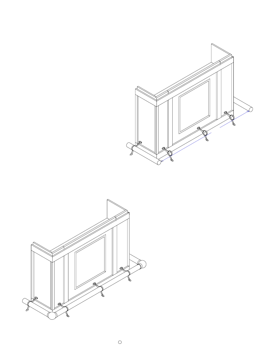
Measure Front Rail Length - Assemble Rails
Page 27
Copyright
2005 by Robert E. Reedy, Vandalia, Ohio
c
Insert a piece of tubing in each
side support as shown. Have
someone help you hold them so
they are parallel to the cabinet and
the floor. Measure the distance
"Y".
This is the length of the front
tubing.
Since the end caps are inserted into the ends of the rail sections,
their screw heads will be on the outside of the rail section.
Assemble the rails as shown to
the left. The end caps go into
the rear of the side rail sections.
I recommend completely
assembling the rail with the
screws provided in the kit and
tighten all the screws enough so
they make visible marks on the
brass rail sections. Then,
disassemble the rail and drill
3/16" holes in the rail where the
screw marks are so the screws
will all fit flush with the bracket
surfaces, elbow collar surfaces,
and at the end caps.
Y
Assemble the Armrest Molding
Page 28
Copyright
2005 by Robert E. Reedy, Vandalia, Ohio
c
The first step in assembling the top is
to assemble the molding as shown
above.
Note: This drawing shows the
molding in an upside down position.
The photos below show a couple of ways to attach the molding corners.
You can join the corners with pocket holes as shown in Figure 1. You'll need a small pocket hole jig for
this.
Note: Be sure to place the pocket holes so the screws don’t come through the top surface of the
molding. Shorter screws may be necessary.
Apply glue and secure with pocket hole screws.
You can secure the joints with finishing nails by temporarily securing the corners using some scrap
plywood with pocket hole screws as shown in Figure 2. Drill two pocket holes on each of two sides of
the plywood. Glue some 100 grit sandpaper to the surface of the scrap plywood where it contacts the lip
of the molding (This makes it grip tighter.) Apply glue to the molding joint then secure the molding with
the scrap plywood to hold the joint firmly together.
Turn the assembly over and secure with two finishing nails as shown
(Be sure to pre-drill the nail holes
so you don't split the wood).
Countersink the nails so you can fill with putty later. Then you can remove
the scrap plywood. The soffit which will be added later will serve to re-enforce the corner joints.
Drill Pocket Holes in the Top
Page 29
Copyright
2005 by Robert E. Reedy, Vandalia, Ohio
c
Drill pocket holes on the bottom surface of the top as
shown. The two pocket holes along the long edge are
used to secure the top to the molding. These two holes
will keep the top centered in the molding and still
allow for expansion or contraction.
26"
26"
2 1/4"
2 1/4"
The pocket holes along the back and cutout
are for mounting the trim. The ones that are
not marked may be placed in
approximately the position shown.
Attach Rear Trim to the Top
Page 30
Copyright
2005 by Robert E. Reedy, Vandalia, Ohio
c
This illustration shows how to clamp a piece of trim to plywood. One clamp holds
the trim piece flush to a flat surface and the other clamp holds the plywood flat to
the same surface. In this case, the plywood represents the bar top. To keep the
pieces flush along the whole piece, you'll want to move the clamps close to each
pocket hole as you insert the screws. This will ensure the trim is flush with the top
surface.
Attach the top trim with glue and pocket hole
screws as shown above. To ensure the top
surfaces of both the Trim and Top are flush,
clamp both pieces to a flat surface before
inserting pocket hole screws.
Flat surface
Plywood
Trim
Attach Risers to the Top
Page 31
Copyright
2005 by Robert E. Reedy, Vandalia, Ohio
c
The above illustration shows now the armrest molding, countertop, risers and
soffit fit together.
Countertop
Riser
Soffit
Trim
1" Screw
1 1/2" Screw
25" Risers
10 3/4" Risers
4 3/4" Risers
Apply some glue and arrange the risers on
the underside of the top as shown. Attach
with either 1 1/8" flathead screws or 1"
finishing nails.
Note: Even though 1 1/8" screws won't penetrate the plywood, they may cause
unsightly bumps on the top surface. To avoid this, pre-drill the screw holes in the
plywood with a bit slightly larger than the inner diameter of the threaded section
of the screws.
4 1/4" Risers
Attach Top to Molding & Attach End Soffit
Page 32
Copyright
2005 by Robert E. Reedy, Vandalia, Ohio
c
Attach the end soffit pieces to the molding
with 1" flat head screws. Attach the end
soffit pieces to the risers with 1 1/8" pan
head screws.
Attach the assembled top to the molding
assembly with pocket hole screws as
shown. Do not glue the top to the molding.
Attach Center Soffit
Page 33
Copyright
2005 by Robert E. Reedy, Vandalia, Ohio
c
54"
14 3/4"
Attach the center soffit pieces to the
outside edge of the molding with 1"
pan head screws. Attach the center
soffit pieces to the risers with 1 1/8"
pan head screws.
This should leave an opening that is 54" between the end pieces of soffit and 14 3/4"
between the center soffit and the rear trim. This is the size of the outside dimensions of the
cabinet top and this opening must fit over the cabinet top.
This drawing shows an upsidedown view of how the
cabinet and top are attached. Use two corner brackets on
each end and three in the middle. You don't want to
actually turn the bar upside down to attach the top,
it may damage it.
Spacing of the corner brackets
is not critical. The cabinet trim
is not shown for clarity.
Note: You should predrill the bracket screw holes in the top and use screws that go no more
that 1/2" into the wood. Otherwise, the bracket screws may cause unsightly bumps on the top
surface of the Bar Top.
Assemble Drawers
Page 34
Copyright
2005 by Robert E. Reedy, Vandalia, Ohio
c
Step 2
Step 3
Left Side
Step 1
Right Side
Front
Back
Step 5
Step 4
Drawer Slide
Support the drawer boxes with 1/2" thick strips of wood and attach the drawer fronts
with 1 1/8" screws as shown in Step 4. This is necessary because the bottom of the
front must be 1/2" below the bottom of the box so it will overlap the rear cabinet trim
when installed. Next, attach the drawer slides as shown in Step 5.
Apply a little glue to the mating surfaces and assemble the drawer boxes.
Assemble the front, back, and right side with 1" long finishing nails as shown in
Step 1. Insert the bottom as shown in Step 2. Attach the left side as shown in Step 3.
Assemble Wine Racks
Page 35
Apply a little glue to the mating surfaces and assemble the wine
racks as shown.
Copyright
2005 by Robert E. Reedy, Vandalia, Ohio
c
4 1/2"
Step 2
Two edge dividers are mounted flush
with sides of the base. The center one
is centered and the other two are 4 1/2"
from the edge of the base to the center
of the dividers.
Step 1
Mount the front to the base with
pocket hole screws. The base and front
are flush on the bottom and the base is
centered between the edges of the
front.
Pocket Holes
Back
Drawer Slide
Attach the back to the base with
finishing nails or screws as you prefer.
Attach the drawer slides as shown with
the screws that were provided with the
drawer slides.
Step 3
This completes the assembly of your home bar. Be sure to countersink and fill all
finishing nails holes before applying the finish.
Copyright
2005 by Robert E. Reedy, Vandalia, Ohio
C
Bar Top
Cabnit Side
Cabnit Side
Divider
Divider
Kick Panel
Left Front Panel
14" Cleat
14" Cleat
Front Cleat
Front Cleat
Small Shelf
14"
Right Front Panel
Workshelf
Bottom
Center Front Panel
41"
Direction of Grain:
Wine Rack Bottom
Wine Rack Bottom
14" Cleat
14" Cleat
14" Cleat
14" Cleat
14" Cleat
14" Cleat
14" Cleat
14" Cleat
14" Cleat
14" Cleat
14" Cleat
14" Cleat
14" Cleat
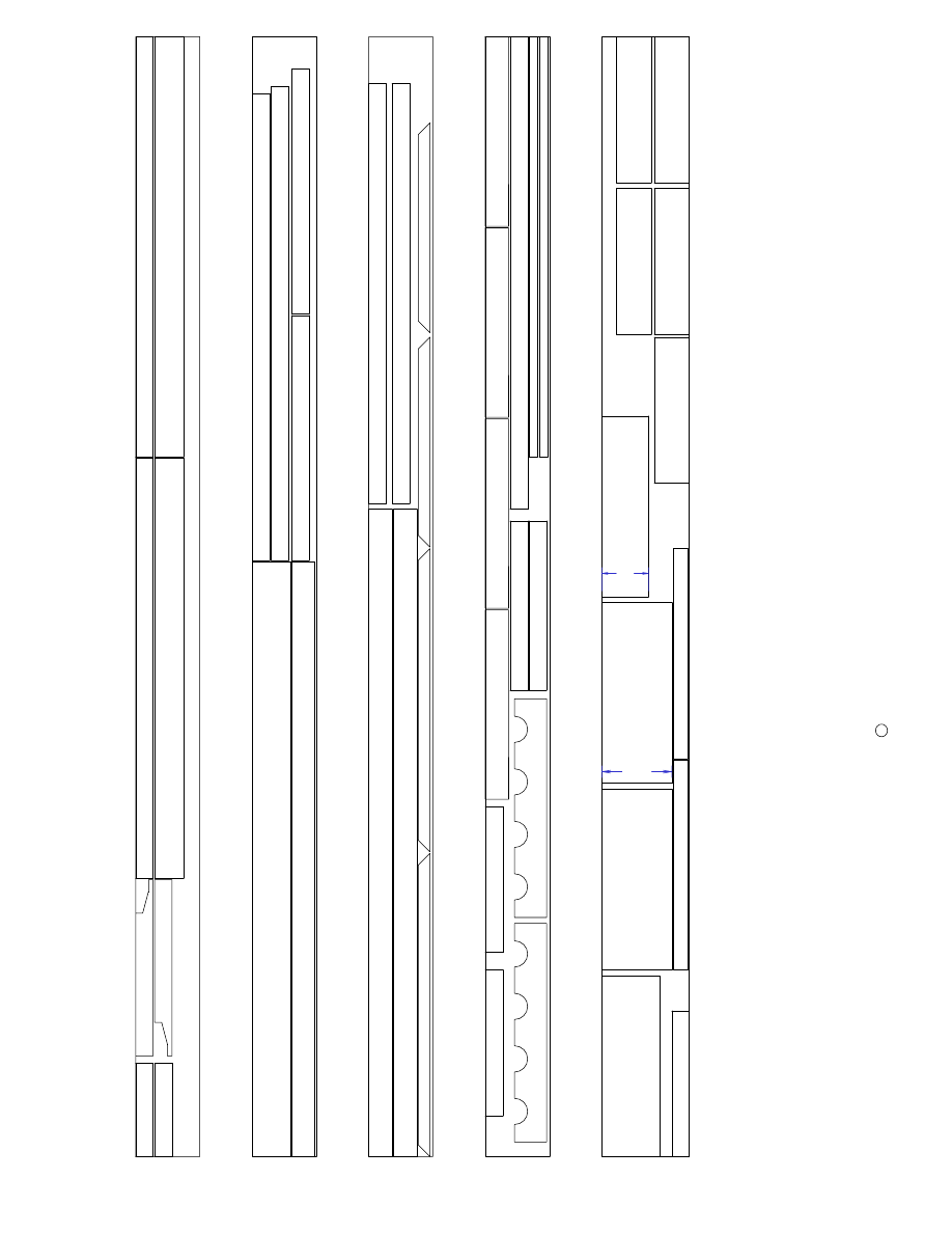
These layout diagrams show how to cut the parts from two pieces of 3/4" oak plywood. Note: Since the
Center Front Panel and Small Shelf are almost square, they have an indicator arrow and dimension line to
ensure you have the grain oriented properly. The other parts are more obvious since they are not as close
to being square.
You can cut the small shelf a little larger than it's listed size with a jig saw and true it up with a table saw
since it will still have one straight edge.
Cutout Suggestions (1)
Page 36
Cutout Suggestions (2)
Copyright
2005 by Robert E. Reedy, Vandalia, Ohio
C
The drawer bottoms are made from 1/4" hardboard.
Page 37
End Soffit
End Soffit
Center Soffit
Cutout diagrams for the soffit and drawer box parts from 1/2" oak plywood. Cutout diagrams for
risers are not given as they may be made from scrap wood.
Top Drawer Box Front
Top Drawer Box Back
Middle Drawer Box Front
Middle Drawer Box Back
Lower Drawer Box Front
Lower Drawer Box Back
Top Drawer Box Side
Top Drawer Box Side
Middle Drawer Box Side
Middle Drawer Box Side
Lower Drawer Box Side
Lower Drawer Box Side
Drawer Bottom
Drawer Bottom
Drawer Bottom
24"
48"
C
u
to
u
t
S
u
g
g
e
s
ti
o
n
s
(3
)
P
a
g
e
3
8
C
o
p
y
ri
g
h
t
2
0
0
5
b
y
R
o
b
e
rt
E
.
R
e
e
d
y
,
V
a
n
d
a
lia
,
O
h
io
C
If
y
o
u
'r
e
m
ak
in
g
t
w
o
w
in
e
ra
ck
s,
y
o
u
'l
l
st
il
l
n
ee
d
o
n
e
m
o
re
w
in
e
ra
ck
s
id
e
an
d
d
iv
id
er
.
H
o
p
ef
u
ll
y
,
y
o
u
'l
l
h
av
e
so
m
e
sm
al
l
p
ie
ce
s
o
f
o
ak
l
y
in
g
a
ro
u
n
d
t
o
m
ak
e
th
em
f
ro
m
.
S
in
ce
t
h
es
e
ar
e
in
si
d
e
p
ar
ts
,
y
o
u
c
o
u
ld
m
ak
e
th
em
f
ro
m
s
o
m
e
o
th
er
m
at
er
ia
l
ra
th
er
t
h
an
b
u
y
a
n
e
x
tr
a
p
ie
ce
o
f
o
ak
.
If
s
o
,
y
o
u
p
ro
b
ab
ly
w
o
u
ld
w
an
t
to
m
ak
e
th
e
re
st
o
f
th
e
in
si
d
e
w
in
e
ra
ck
p
ar
ts
f
ro
m
t
h
e
sa
m
e
m
at
er
ia
l
to
o
.
C
o
rn
e
rT
ri
m
C
o
rn
e
rT
ri
m
R
e
a
r
C
o
u
n
te
rt
o
p
T
ri
m
R
e
a
r
C
o
u
n
te
rt
o
p
T
ri
m
S
id
e
C
u
to
u
t
T
ri
m
S
id
e
C
u
to
u
t
T
ri
m
F
lu
te
d
T
ri
m
F
lu
te
d
T
ri
m
R
e
a
r
T
o
p
H
o
ri
z
o
n
ta
l
T
ri
m
R
a
e
r
B
o
tt
o
m
H
o
ri
z
o
n
ta
l
T
ri
m
B
a
c
k
C
o
rn
e
r
T
ri
m
B
a
c
k
C
o
rn
e
r
T
ri
m
V
e
rt
ic
a
l
D
iv
id
e
r
T
ri
m
V
e
rt
ic
a
l
D
iv
id
e
r
T
ri
m
F
ro
n
t
B
o
tt
o
m
T
ri
m
C
o
rn
e
rT
ri
m
C
o
rn
e
rT
ri
m
T
o
p
D
e
c
o
t
ri
m
B
o
tt
o
m
D
e
c
o
t
ri
m
S
id
e
D
e
c
o
t
ri
m
S
id
e
D
e
c
o
t
ri
m
F
ro
n
t
T
o
p
T
ri
m
S
id
e
T
ri
m
S
id
e
T
ri
m
S
id
e
T
ri
m
S
id
e
T
ri
m
C
e
n
te
r
C
u
to
u
t
T
ri
m
D
ra
w
e
r
D
iv
id
e
r
T
ri
m
D
ra
w
e
r
D
iv
id
e
r
T
ri
m
S
id
e
C
o
rn
e
r
T
ri
m
S
id
e
C
o
rn
e
r
T
ri
m
W
in
e
R
a
c
k
S
id
e
W
in
e
R
a
c
k
S
id
e
W
in
e
R
a
c
k
F
ro
n
t
W
in
e
R
a
c
k
F
ro
n
t
M
id
d
le
D
ra
w
e
r
F
ro
n
t
T
o
p
D
ra
w
e
r
F
ro
n
t
L
o
w
e
r
D
ra
w
e
r
F
ro
n
t
T
o
p
H
a
lf
L
o
w
e
r
D
ra
w
e
r
F
ro
n
t
B
o
tt
o
m
H
a
lf
W
in
e
R
a
c
k
S
id
e
W
in
e
R
a
c
k
D
iv
id
e
r
W
in
e
R
a
c
k
D
iv
id
e
r
W
in
e
R
a
c
k
D
iv
id
e
r
W
in
e
R
a
c
k
D
iv
id
e
r
W
in
e
R
a
c
k
D
iv
id
e
r
W
in
e
R
a
c
k
B
a
c
k
W
in
e
R
a
c
k
B
a
c
k
6"
4"
C
u
to
u
t
d
ia
g
ra
m
s
fo
r
th
e
p
ar
ts
t
h
at
a
re
m
ad
e
fr
o
m
s
o
li
d
o
ak
.
Wyszukiwarka
Podobne podstrony:
Table Dry Bar Plans
(Ebooks) Diy Woodwork Plans Kitchen Cabinets
Wood Working Plan Arcade Cabinet Plans
Cabinet Buffet And China Cabinet Plans
Cabinet Entertainment Center Plans
Cabinet Entertainment Center Plans
Garret Water Carburator Plans For Water Powered Vehicles
DIY Mortis Dreadmought Plans & Templates
Complete Circuit diagram and plans
Corner Buffet Cabinet(1)
Piwa, Bar
FLEXI BAR poster2
cabinetmakerupho00sher
Corner Cabinet 1
Bar do t’os grol cz’en mo Wielkie Wyzwolenie z Bar do przez słuchanie
KORESPONDECJA PRACOWNICZA, zaświadczenie, Cocktail Bar „Corin”
BAR DO THOS GROLczyliTYBETAŃSKA KSIĘGA UMARŁYCH
więcej podobnych podstron