Air-Conditioners For Building Application
INDOOR UNIT
PKFY-P·VBM-E
MANUAL DE INSTALAÇÃO
Para segurança e utilização correctas, leia atentamente este manual de instalação antes de instalar a unidade
de ar condicionado.
INSTALLATION MANUAL
For safe and correct use, please read this installation manual thoroughly before installing the air-conditioner unit.
INSTALLATIONSHANDBUCH
Zum sicheren und ordnungsgemäßen Gebrauch der Klimaanlage das Installationshandbuch gründlich durch-
lesen.
MANUEL D’INSTALLATION
Veuillez lire le manuel d’installation en entier avant d’installer ce climatiseur pour éviter tout accident et vous as-
surer d’une utilisation correcte.
INSTALLATIEHANDLEIDING
Voor een veilig en juist gebruik moet u deze installatiehandleiding grondig doorlezen voordat u de airconditioner
installeert.
MANUALE DI INSTALLAZIONE
Per un uso sicuro e corretto, leggere attentamente questo manuale di installazione prima di installare il con-
dizionatore d’aria.
MANUAL DE INSTALACIÓN
Para un uso seguro y correcto, lea detalladamente este manual de instalación antes de montar la unidad de aire
acondicionado.
FOR INSTALLER
FÜR INSTALLATEURE
POUR L’INSTALLATEUR
VOOR DE INSTALLATEUR
PARA EL INSTALADOR
PER L’INSTALLATORE
PARA O INSTALADOR
安装说明书
在安装空调机之前,请先通读此安装说明书,以便安全正确地使用。
安装人员适用
ΕΓΧΕΙΡΙΔΙΟ ΟΔΗΓΙΩΝ ΕΓΚΑΤΑΣΤΑΣΗΣ
Για ασφάλεια και σωστή χρήση, лαρακαλείστε διαβάσετε пρоσεχτικά αυτό το εγχειρίδιο εγκατάστασης пριν
αρχίσετε την εγκατάσταση της μονάδας κλιματισμού.
ΓΙΑ ΑΥΤΟΝ ΠΟΥ ΚΑΝΕΙ ΤΗΝ ΕΓΚΑΤΑΣΤΑΣΗ
MONTAJ ELK
İTABI
Emniyetli ve do
ğru biçimde nasıl kullanılacağını öğrenmek için lütfen klima cihazını monte etmeden önce bu
elkitabını dikkatle okuyunuz.
MONTÖR
İÇİN
РУКОВОДСТВО ПО УСТАНОВКЕ
Для осторожного и правильного использования прибора необходимо тщательно ознакомиться с данным
руководством по установке до выполнения установки кондиционера.
ДЛЯ УСТАНОВИТЕЛЯ
Español
Türkçe
Русский
English
Deutsch
中文
Français
Nederlands
Italiano
Português
Ελληνικά
RG79D177H01_0221.indd 1
RG79D177H01_0221.indd 1
22/02/2007 19:08:02
22/02/2007 19:08:02
2
2. Installation location
Fig. 2-1
H
D
W
Warning:
• Ask the dealer or an authorized technician to install the air conditioner.
• Install the unit at a place that can withstand its weight.
• Use the specifi ed cables for wiring.
• Use only accessories authorized by Mitsubishi Electric and ask the dealer
or an authorized technician to install them.
• Do not touch the heat exchanger fi ns.
• Install the air conditioner according to this Installation Manual.
• Have all electric work done by a licensed electrician according to local
regulations.
• If the air conditioner is installed in a small room, measures must be taken to
prevent the refrigerant concentration from exceeding the safety limit even if
the refrigerant should leak.
• The cut face punched parts may cause injury by cut, etc. The installers are
requested to wear protective equipement such as gloves, etc.
Caution:
• Do not use the existing refrigerant piping, when use R410A or R407C refrig-
erant.
• Use ester oil, either oil or alkylbenzene (small amount) as the refrigerator
oil to coat fl ares and fl ange connections, when use R410A or R407C refrig-
erant.
• Do not use the air conditioner where food, pets, plants, precision instru-
ments, or artwork are kept.
• Do not use the air conditioner in special environments.
• Ground the unit.
• Install an leak circuit breaker, as required.
• Use power line cables of suffi cient current carrying capacity and rating.
• Use only a circuit breaker and fuse of the specifi ed capacity.
• Do not touch the switches with wet fi ngers.
• Do not touch the refrigerant pipes during and immediately after operation.
• Do not operate the air conditioner with the panels and guards removed.
• Do not turn off the power immediately after stopping operation.
1. Safety
precautions
.....................................................................................2
2. Installation
location
....................................................................................2
3. Installing the indoor unit ............................................................................3
4. Refrigerant pipe and drain pipe .................................................................4
5. Electrical
work
...........................................................................................6
6. Test
run
......................................................................................................7
Contents
1. Safety precautions
Before installing the unit, make sure you read all the “Safety precau-
tions”.
Please report to your supply authority or obtain their consent before
connecting this equipment to the power supply system.
Warning:
Describes precautions that must be observed to prevent danger of injury or
death to the user.
Caution:
Describes precautions that must be observed to prevent damage to the unit.
After installation work has been completed, explain the “Safety Precautions,” use,
and maintenance of the unit to the customer according to the information in the
Operation Manual and perform the test run to ensure normal operation. Both the
Installation Manual and Operation Manual must be given to the user for keeping.
These manuals must be passed on to subsequent users.
: Indicates an action that must be avoided.
: Indicates an important instructions that must be followed.
: Indicates a part which must be grounded.
: Indicates that caution should be taken with rotating parts.
: Indicates that the main switch must be turned off before servicing.
: Beware of electric shock.
: Beware of hot surface.
ELV
: At servicing, please shut down the power supply for both the Indoor and
Outdoor Unit.
Warning:
Carefully read the labels affi xed to the main unit.
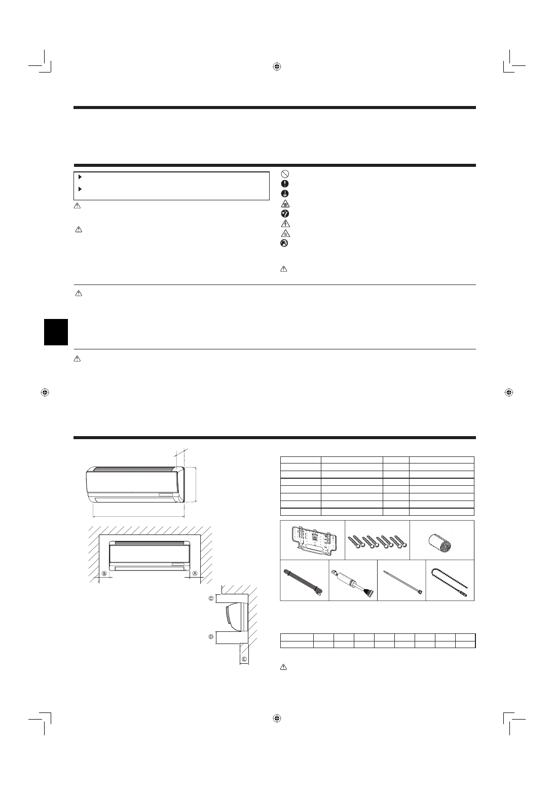
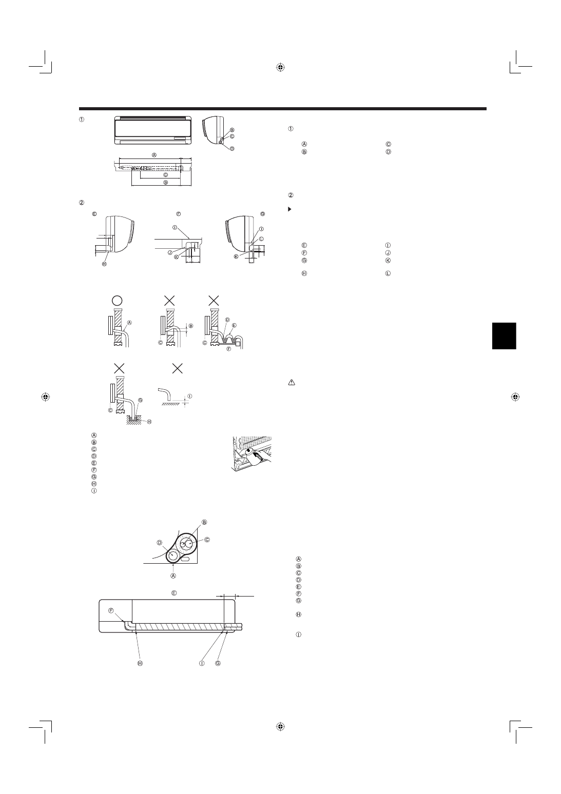
2.1. Outline dimensions (Indoor unit) (Fig. 2-1)
Select a proper position allowing the following clearances for installation and main-
tenance.
(mm)
Models
W
D
H
A
B
C
*1
D
E
PKFY-P·VBM
815
225
295
Min. 20
Min. 22
Min. 50
Min. 100
Max. 90
*1 : 60mm or more for left and left back piping.
Warning:
Mount the indoor unit on a wall strong enough to withstand the weight of the
unit.
The indoor unit comes with the following parts and accessories:
PART NUMBER
ACCESSORY
QUANTITY
LOCATION OF SETTING
1
Wall-fi xing bracket
1
Fix at the back of the unit
2
Tapping screw 4 × 35
8
Set in packing material
3
Felt tape
1
4
MA remote controller cable
1
5
Cable
1
6
Band
1
7
Fastener
1
RG79D177H01_0221.indd 2
RG79D177H01_0221.indd 2
22/02/2007 19:08:05
22/02/2007 19:08:05
3
3. Installing the indoor unit
(mm)
Fig. 3-1
Fig. 3-2
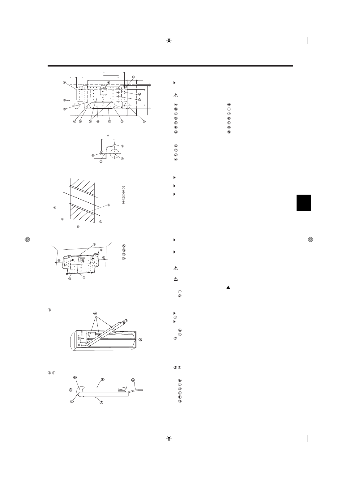
3.1.2. Drilling the piping hole (Fig. 3-2)
Use a core drill to make a hole of 90-100 mm diameter in the wall in the
piping direction, at the position shown in the diagram to the left.
The hole should incline so that the outside opening is lower than the in-
side opening.
Insert a sleeve (with a 90 mm diameter and purchased locally) through the
hole.
Note:
The purpose of the hole’s inclination is to promote drain fl ow.
Sleeve
Hole
(Indoors)
Wall
(Outdoors)
3.1.3. Installing the wall mounting fi xture
Since the indoor unit weighs near 10 kg, selection of the mounting loca-
tion requires thorough consideration. If the wall does not seem to be
strong enough, reinforce it with boards or beams before installation.
The mounting fi xture must be secured at both ends and at the centre, if
possible. Never fi x it at a single spot or in any unsymetrical way.
(If possible, secure the fi xture at all the positions marked with a bold ar-
row.) (Fig. 3-3)
Warning:
If possible, secure the fi xture at all positions indicated with a bold arrow.
Caution:
• The unit body must be mounted horizontally.
• Fasten at the holes marked with
as shown by the arrows.
Fasten a thread to the hole.
The level can be easily obtained by hanging a weight from the string and aligning the
string with the mark.
3.2. Preparation for piping connection
Remove the vinyl band that holds the drain pipe.
Rear, right and lower piping (Fig. 3-4)
Bind the refrigerant pipes and drain pipe with vinyl tape at three or more
points. This will facilitate passing the pipes through the wall.
Vinyl tape
This fi gure is viewed from the back of the unit.
Left and left rear piping
-
For left rear piping, pull the pipes out the hole to determine their correct
length, then bend them. The indoor unit should hang on the wall mounting
fi xture. (Fig. 3-5)
Wall
Wall hole
Bent section
Refrigerant pipe
Drain pipe
Transmission cable
Fig. 3-3
Fig. 3-4
Fig. 3-5
Min. 100 mm
Min. 130 mm
Min. 59 mm
*1
Mount board
*1: 69mm or more for left and left
back piping
40.5
245.5
196.5
3
283
9
250
190
450
109.5
450
79.5
79.5
328
298
109.5
10
5
100
450
-
3.1. Installing the wall mounting fi xture (Fig. 3-1)
3.1.1. Setting the wall mounting fi xture and piping positions
Using the wall mounting fi xture, determine the unit’s installation position
and the locations of the piping holes to be drilled.
Warning:
Before drilling a hole in the wall, you must consult the building contractor.
Supporting piece
Knockout hole (12-ø2.6)
Mount board
Knockout hole (4-ø9)
Main body
Knockout hole (87-ø5.4)
Slot (4-4.5 × 35)
Piping hole (ø65)
Knockout hole (8-ø4.3)
Slot (4-4.5 × 40)
Level setting standard
Slot (4-4.5 × 37)
Knockout hole
Slot (4-11 × 20)
W: Location for wall holes
Wall mounting fi xture
Hole centre
Align the scale with the line.
Insert scale.
RG79D177H01_0221.indd 3
RG79D177H01_0221.indd 3
22/02/2007 19:08:06
22/02/2007 19:08:06
4
Fig. 3-6
Fig. 3-7
Fig. 3-8
3. Installing the indoor unit
4. Refrigerant pipe and drain pipe
90 ±0.5
øA
R0.4~R0.8
45 ±2
Fig. 4-1
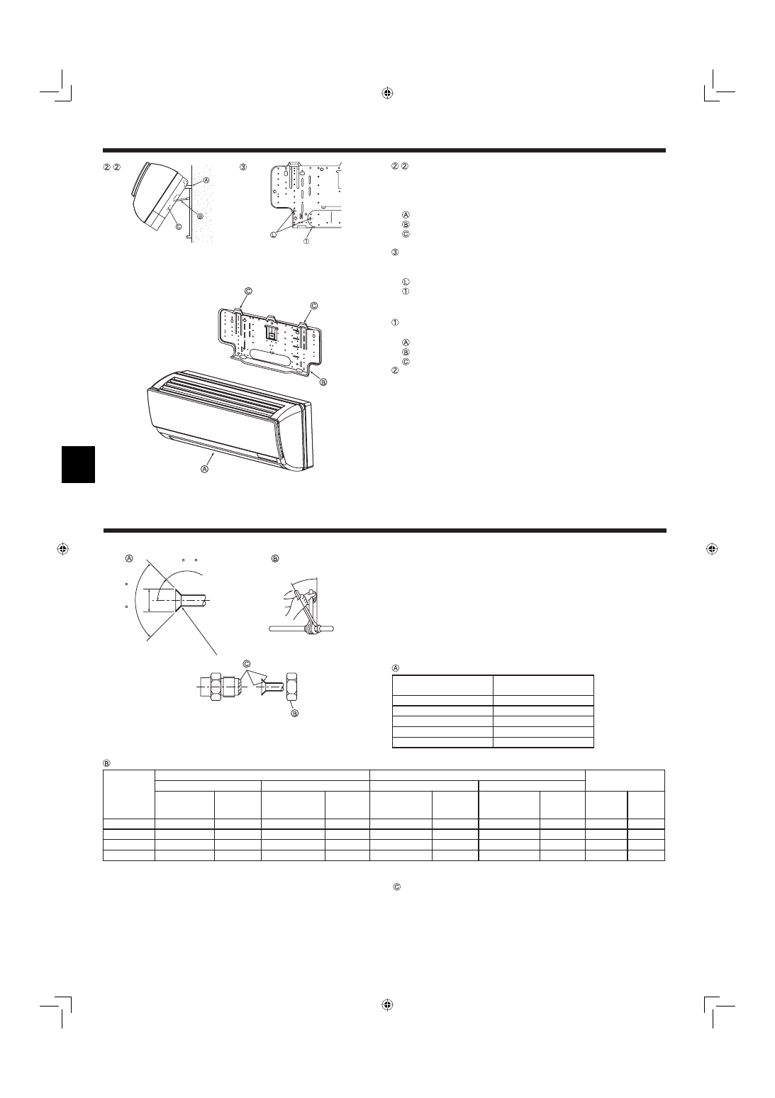
4.1. Connecting pipes (Fig. 4-1)
• When commercially available copper pipes are used, wrap liquid and gas pipes
with commercially available insulation materials (heat-resistant to 100 °C or more,
thickness of 12 mm or more).
• The indoor parts of the drain pipe should be wrapped with polyethylene foam in-
sulation materials (specifi c gravity of 0.03, thickness of 9 mm or more).
• Apply thin layer of refrigerant oil to pipe and joint seating surface before tighten-
ing fl are nut.
• Use two wrenches to tighten piping connections.
• Use refrigerant piping insulation provided to insulate indoor unit connections. In-
sulate carefully.
Flare cutting dimensions
Copper pipe O.D.
(mm)
Flare dimensionsøA dimen-
sions (mm)
ø6.35
8.7 - 9.1
ø9.52
12.8 - 13.2
ø12.7
16.2 - 16.6
ø15.88
19.3 - 19.7
ø19.05
22.9 - 23.3
-
Lift the indoor unit by hooking the supporting piece (attached to the mount
board) to the ribs on the back of the unit as shown. (Fig. 3-6)
When piping work etc. is complete, replace the supporting piece on the
mount board.
(If the unit is not fi xed securely, vibration may occur during operation.)
Mount board
Supporting piece
Rib
If the fl are pipe is to be embedded into the wall in advance: (Fig. 3-7)
• Determine the length of pipe to be embedded by marking on the mounting plate
as a reference.
Mark
Wall mounting fi xture
3.3. Mounting the unit (Fig. 3-8)
Securely place the hanging fi xtures for the indoor unit over the catches on the
wall mounting fi xture.
Indoor unit
Wall mounting fi xture
Catch
When piping has been completed, install the indoor unit and wall mounting fi x-
ture with fi xing screws.
-
Refrigerant pipe sizes & Flare nut tightening torque
R407C or R22
R410A
Flare nut O.D.
Liquid pipe
Gas pipe
Liquid pipe
Gas pipe
Pipe size(mm)
Tighten-
ing torque
(N.m)
Pipe size (mm)
Tightening
torque
(N.m)
Pipe size (mm)
Tightening
torque
(N.m)
Pipe size (mm)
Tightening
torque
(N.m)
Liquid pipe
(mm)
Gas pipe
(mm)
P20/25/32/40
ODø6.35 (1/4”)
14 - 18
ODø12.7 (1/2”)
49 - 61
ODø6.35 (1/4”)
14 - 18
ODø12.7 (1/2”)
49 - 61
17
26
P50
ODø9.52 (3/8”)
34 - 42*
ODø15.88 (5/8”)
68 - 82*
ODø6.35 (1/4”)
34 - 42
ODø12.7 (1/2”)
68 - 82
22
29
P63/80
ODø9.52 (3/8”)
34 - 42
ODø15.88 (5/8”)
68 - 82
ODø9.52 (3/8”)
34 - 42
ODø15.88 (5/8”)
68 - 82
22
29
P100/125
ODø9.52 (3/8”)
34 - 42
ODø19.05 (3/4”)
100 - 120*
ODø9.52 (3/8”)
34 - 42
ODø15.88 (5/8”)
100 - 120
22
36
* Use the provided fl are nut for the following pipes: Liquid pipe of P50, gas pipe of P50, P100, P125.
Apply refrigerating machine oil over the entire fl are seat surface.
RG79D177H01_0221.indd 4
RG79D177H01_0221.indd 4
22/02/2007 19:08:07
22/02/2007 19:08:07
5
4. Refrigerant pipe and drain pipe
(mm)
Fig. 4-2
Fig. 4-4
Fig. 4-3
Fig. 4-5
660
110
450
520
116
54
24.4
10
45
10
50
2.5
16
45 91.5
10
34
4
50
16
2.5
4.3. Drain piping (Fig. 4-4)
• Drain pipes should have an inclination of 1/100 or more.
• For extension of the drain pipe, use a soft hose (inner dia. 16 mm) available on
the market or hard vinyl chloride pipe (VP-16). Make sure that there is no water
leakage from the connections.
• If the drain pipe passes indoors it must be covered with insulating material (foamed
polyethylene: specifi c gravity: 0.03, thickness: 9 mm or more) available on the
market.
• Do not put the drain piping directly in a drainage ditch where sulphuric gas may
be generated.
• When piping has been completed, check that water fl ows from the end of the
drain pipe.
Caution:
The drain pipe should be installed according to this Installation Manual to
ensure correct drainage. Thermal insulation of the drain pipes is necessary
to prevent condensation. If the drain pipes are not properly installed and in-
sulated, condensation may drip on the ceiling, fl oor or other possessions.
Inclined downwards
Must be lower than outlet point
Water leakage
Trapped drainage
Air
Wavy
The end of drain pipe is under water.
Drainage ditch
5 cm or less between the end of drain pipe and
the ground
100
(mm)
4.2. Positioning refrigerant and drain piping
Position of refrigerant and drain piping (Fig. 4-2)
• The drain pipe can be cut midway to meet the on-site conditions.
(Total length of fl exible hose)
Gas pipe
Liquid pipe
Drain hose
Determine the position of the knockout holes on the unit body. (Fig. 4-3)
Cut the knockout holes using a saw blade or an adequate knife.
Take care not to damage other parts of the unit.
• Remove the corner box and drill a knockout hole. If a hole is made without remov-
ing the box, the drain hose could be damaged.
Left-side piping
Corner box
Lower piping
Knockout hole for lower piping
Right-side piping
Through hole for the remote controller’s
cable
Knockout hole for left-side piping
Knockout hole for right-side piping
4.4. Completing the piping (Fig. 4-5)
• To prevent condensation from dripping, put felt tape over the insulation materials
on the refrigerant and drain pipes within the unit as shown in the diagram.
• Arrange the drain hose so that it goes to the bottom of the unit.
• The overlapping width of felt tape is one half of the tape width.
Felt tape
Liquid pipe
Gas pipe
Drain piping
Viewed from the back
Take care that the middle of the drain hose is not raised.
In the case of left piping, the refrigerant pipes and the drain pipe should be taped
separately.
Wrap together the refrigerant pipes and the drain pipe with felt tape so that white felt over
laps by 20 mm or more.
* The pipes should be wrapped so that they are housed behind the unit.
Fix the end of the felt tape with a bandage fi xture.
(mm)
RG79D177H01_0221.indd 5
RG79D177H01_0221.indd 5
22/02/2007 19:08:08
22/02/2007 19:08:08
6
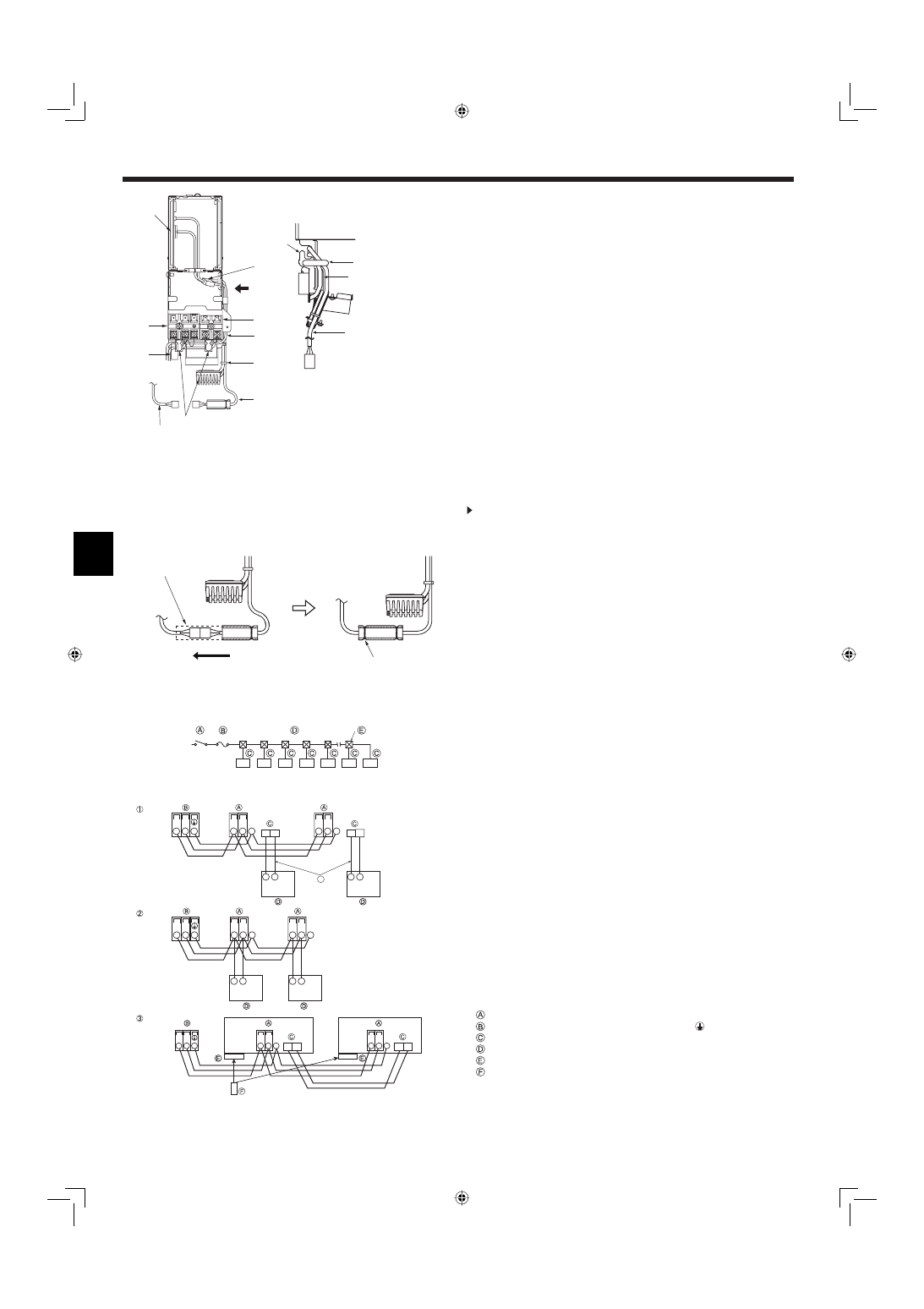
5. Electrical work
Fig. 5-1
A
Terminal block for power supply
B
Terminal block for transmission cable (Shared with the M-NET remote controller)
C
Connector for MA remote controller
D
MA remote controller cable (ACCESSORY
4
)
E
Cable (ACCESSORY
5
)
F
Band (ACCESSORY
6
)
G
The clamp for on-site wiring
Fig. 5-4
S
S
TB3
TB5
TB5
M1 M2
M1 M2
M1 M2
2
1
2
1
a
S
S
TB3
M1 M2
TB5
M1 M2
TB5
M1 M2
2
1
2
1
TB5
Pair No.
0
Pair No.
0
Pair No.
0
TB5
S
M1 M2
S
M1 M2
TB3
M1 M2
5.1. Indoor unit (Fig. 5-1,5-2)
1) Remove the front panel, then remove the corner box from the lower right corner
of the indoor unit.
2) Remove the screw fi xing the electric parts cover and remove the cover.
3) Connect the power cable and transmission cable to the terminal block.
• The electric parts box may have to be pulled forward during customer service
etc. Therefore, the wires must have some extra length.
4) Connect the connector for MA remote controller.(Non-polarized 2-wire)
5) Connect the attached cable 5 to the CN90 on controller board in the electrical
parts box.
* Be sure to connect in case of using MA/M-NET Remote controller.
6) Fix the MA Remote controller cable 4 and the cable 5 with the clamp through
the claw on the right side of the electrical parts box.
7) Fix the MA remote controller cable 4 on the fi xing clamp with the cable running
along the down side of the terminal block.
8) Fix the cable 5 with the attached band 6.
9) Bring out the lead wire on the back side of the front panel to the corner box side.
Put back the electrical cover and front panel.(Do not pull the lead wire strongly.)
10) After connecting the connectors (yellow 9-pole) on the indoor unit and front
panel, slide the glass tube and fi x it with the attached fastener 7 at which the
connector joint part is not exposed.
* Be sure to connect in case of using MA/M-NET Remote controller.
11) Fix each wire with the clamp for on-site wiring under the electrical parts box
and put the corner box cover back.
A means for the disconnection of the supply with an isolation switch, or similar de-
vice, in all active conductors shall be incorporated in the fi xed wiring.
Selecting non-fuse breaker (NF) or earth leakage breaker (NV).
For breaker, means shall be provided to ensure disconnection of all active phase
conductors of the supply.
Power supply wiring
• Install an earth longer than other cables.
• Power supply codes of appliance shall not be lighter than design 60245 IEC 53 or
60227 IEC 53.
• A switch with at least 3 mm contact separation in each pole shall be provided by
the air conditioner installation.
Power cable size : more than 1.5 mm
2
.
[Fig.5-3]
A Switch 16 A
D Total operating current be less than 16 A
B Overcurrent protection 16 A
E Pull box
C Indoor unit
5.2. Connecting remote controller, indoor and outdoor
transmission cables (Fig. 5-4)
• Connect indoor unit TB5 and outdoor unit TB3. (Non-polarized 2-wire)
The “S” on indoor unit TB5 is a shielding wire connection. For specifi cations about
the connecting cables, refer to the outdoor unit installation manual.
Note:
As for PKFY-P.BM series, TB5 has two terminals and does not have S terminal.
The earths of shielding wires are crimping-connected. Insulate the connected
parts with insulating tapes and so on.
• Install a remote controller following the manual supplied with the remote controller.
• Connect the remote controller’s transmission cable within 10 m using a 0.75 mm
2
core cable. If the distance is more than 10 m, use a 1.25 mm
2
junction cable.
1 MA Remote controller
• Connect the connector for MA remote controller. (Non-polarized 2-wire)
• DC 9 to 13 V between 1 and 2 (MA remote controller)
a
MA remote controller cable (ACCESSORY
4
)
2 M-NET Remote controller
• Connect the “M1” and “M2” on indoor unit TB5 to a M-NET remote controller.
(Non-polarized 2-wire)
• DC 24 to 30 V between M1 and M2 (M-NET remote controller)
3 Wireless remote controller
• When more than two units are run under group control using wireless remote
controller, connect TB15 each with the same number.
• To change Pair No. setting, refer to installation manual attached to wireless remote
controller. (In the default setting of indoor unit and wireless remote controller, Pair No.
is 0.)
Terminal block for indoor transmission cable
Terminal block for outdoor transmission cable (M1(A), M2(B),
(S))
Connector for MA remote controller
Remote controller
Wireless signal receiver
Wireless remote controller
Fig. 5-3
Cable(Front panel side)
Fasten the cables with the clamp
CN90
/
Clamp
Claw
M2
M1
N
L
Right side view (from
/
)
Fig. 5-2
Direction to slide
Connect the connector
Fastener
(Leave about four beads
and cut the rest. )
RG79D177H01_0221.indd 6
RG79D177H01_0221.indd 6
22/02/2007 19:08:09
22/02/2007 19:08:09
7
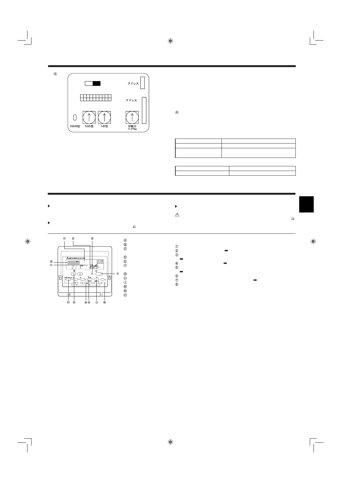
Fig. 5-5
SW14
0
SW11
0
SW12
0
1 2 3 4 5 6 7 8 9 10
ON
OFF
SW1
SW5
220V
240V
CN82
CN43
5.3. Setting addresses (Fig. 5-5)
(Be sure to operate with the main power turned OFF.)
• There are two types of rotary switch setting available: setting addresses 1 to 9
and over 10, and setting branch numbers.
Note:
Please set the switch SW5 according to the power supply voltage.
• Set SW5 to 240 V side when the power supply is 230 and 240 volts.
• When the power supply is 220 volts, set SW5 to 220 V side.
Address board
5.4. Types of control cables
1. Wiring transmission cables: Shielding wire CVVS or CPEVS
• Cable diameter: More than 1.25 mm
2
2. M-NET Remote control cables
Kind of remote control cable
Shielding wire MVVS
Cable diameter
More than 0.5 to 1.25 mm
2
Remarks
When 10 m is exceeded, use cable with the
same specifi cations as transmission line wiring
3. MA Remote control cables
Kind of remote control cable
2-core cable (unshielded)
Cable diameter
0.3 to 1.25 mm
2
5. Electrical work
6. Test run
Do not carry out this test on the control wiring (low voltage circuit) termi-
nals.
Warning:
Do not use the air conditioner if the insulation resistance is less than 1.0 M .
6.1. Before test run
After completing installation and the wiring and piping of the indoor and
outdoor units, check for refrigerant leakage, looseness in the power sup-
ply or control wiring, wrong polarity, and no disconnection of one phase in
the supply.
Use a 500-volt megohmmeter to check that the resistance between the
power supply terminals and ground is at least 1.0 M .
Fig. 6-1
°C
°C
SIMPLE
PAR-21MAA
ON/OFF
FILTER
CHECK
OPERATION
CLEAR
TEST
TEMP.
MENU
BACK
DAY
MONITOR/SET
CLOCK
ON/OFF
TEST RUN
COOL, HEAT
ON/OFF button
Test run display
Liquid pipe (Indoor unit)
temperature display
ON/OFF lamp
Power display
Error code display
Test run remaining time display
Set temperature button
Mode selection button
Air direction button
TEST button
Fan Speed button
Louver button
6.2. Test run
Using wired remote controller (Fig. 6-1)
Turn on the power at least 12 hours before the test run.
Press the [TEST] button twice.
“TEST RUN” liquid crystal display
Press the [Mode selection] button and switch to the cooling (or heating) mode.
Make sure that cold (or warm) wind is blown out.
Press the [Fan speed] button.
Make sure that the wind speed is switched.
Press the [Air direction button] or [Louver button].
Check operation of the vane or louver.
Check operation of the outdoor unit fan.
Release test run by pressing the [ON/OFF] button.
Stop
Register a telephone number.
The telephone number of the repair shop, sales offi ce, etc., to contact if an error
occurs can be registered in the remote controller. The telephone number will be
displayed when an error occurs. For registration procedures, refer to the opera-
tion manual for the indoor unit.
Note:
• If an error code is displayed on the remote controller or if the air condition-
er does not operate properly, refer to the outdoor unit installation manual or
other technical materials.
• The OFF timer is set for the test run to automatically stop after 2 hours.
• During the test run, the time remaining is shown in the time display.
• During the test run, the temperature of the indoor unit refrigerant pipes is
shown in the room temperature display of the remote controller.
• When the VANE or LOUVER button is pressed, the message “NOT AVAILA-
BLE” may appear on the remote controller display depending on the indoor
unit model, but this is not a malfunction.
RG79D177H01_0221.indd 7
RG79D177H01_0221.indd 7
22/02/2007 19:08:10
22/02/2007 19:08:10
Please be sure to put the contact address/telephone number on
this manual before handing it to the customer.
Low Voltage Directive 2006/95/EC
Electromagnetic Compatibility Directive
89/336/ EEC
This product is designed and intended for use in the residential,
commercial and light-industrial environment.
HEAD OFFICE: TOKYO BLDG., 2-7-3, MARUNOUCHI, CHIYODA-KU, TOKYO 100-8310, JAPAN
Printed in Japan
RG79D177H01
The product at hand is
based on the following
EU regulations:
RG79D177H01_0221.indd 8
RG79D177H01_0221.indd 8
22/02/2007 19:08:11
22/02/2007 19:08:11
Document Outline
- 01_RG79D177H01_EN_0221.indd.pdf
- 02_RG79D177H01_GE_0221.indd.pdf
Wyszukiwarka
Podobne podstrony:
IM PFFY P20 63VLRMM E WT05228X01 GB 2007
IM MSZ FD25 35VA SG79Y970H07 GB 2007
IM PKFY P63 100VFM E BG79U776H01 GB 2006
IM PKFY P32 50VGM E BG79U323H02 GB 2004
IM PUHZ HRP71 100 125VHA YHA RG79D355H02 GB 2007
IM PAC AH125 140 250M H WT04980X02 GB 2007
IM PUHZ RP200 250YHA BG79U637H03 GB 03 2007
gb 2007 8 5 r95
IM PCFY P40 125VKM E RG79D452H01 GB 01 2009
IM PEFY P15 63VMS1 L E KB79H130H03 GB 08 2009
IM PAC IF011B E IF012B E BH79D099H02 GB 09 2009
IM CMY R100 200VBK WT05221X02 GB Dec 2008
IM PEFY P40 250VMH E WT04198X02 GB 2005
IM PLFY P20 25 32 40VCM E BG79U363H01 2004
IM MSZ GA50 71VA SG79Y434H01 GB 07 2005
więcej podobnych podstron