Manual
USB-to-CAN compact
Intelligent PC/CAN Interface

IXXAT Automation GmbH
Leibnizstr. 15
88250 Weingarten
Germany
Tel.: +49 751 56146-0
Fax: +49 751 56146-29
Internet: www.ixxat.com
E-Mail: info@ixxat.com
Support
In case of unsolvable problems with this product or other IXXAT products
please contact IXXAT in written form by:
Fax: +49 751 56146-29
E-Mail: support@ixxat.de
Further international support contacts can be found on our webpage
www.ixxat.com
Copyright
Duplication (copying, printing, microfilm or other forms) and the electronic
distribution of this document is only allowed with explicit permission of
IXXAT Automation GmbH. IXXAT Automation GmbH reserves the right to
change technical data without prior announcement. The general business
conditions and the regulations of the license agreement do apply. All rights
are reserved.
Registered trademarks
All trademarks mentioned in this document and where applicable third par-
ty registered are absolutely subject to the conditions of each valid label right
and the rights of particular registered proprietor. The absence of identifica-
tion of a trademark does not automatically mean that it is not protected by
trademark law.
Document number: 4.01.0087.30000
Version: 1.6

Copyright IXXAT Automation GmbH
USB-to-CAN compact - Manual, V1.6
Contents
3
1
Introduction .............................................................................. 5
1.1
Overview ............................................................................. 5
1.2
Features .............................................................................. 5
2
Installation ................................................................................. 5
2.1
Software installation .......................................................... 5
2.2
Hardware installation ......................................................... 5
3
Connections and displays .......................................................... 6
3.1
Pin allocation ...................................................................... 6
3.1.1
USB connector ........................................................................... 6
3.1.2
CAN bus connector ................................................................... 6
3.1.2.1
USB-to-CAN compact .................................................................. 6
3.1.2.2
USB-to-CAN compact RJ45 .......................................................... 7
3.2
Displays ............................................................................... 7
3.3
CAN bus termination .......................................................... 7
4
Appendix ................................................................................... 8
4.1
Support ............................................................................... 8
4.2
Returning hardware ............................................................ 8
4.3
Technical specifications ....................................................... 9
4.4
Accessories ........................................................................ 10
CAN bus termination resistor ............................................................. 10
Cable adapter RJ45 to Sub-D9M ........................................................ 10
4.5
Note on disposal of used devices ..................................... 11
4.6
Declaration of conformity................................................. 12
4.7
FCC Compliance ................................................................ 13


Copyright IXXAT Automation GmbH
USB-to-CAN compact - Manual, V1.6
Introduction
5
1 Introduction
1.1 Overview
Congratulations on your purchase of the IXXAT PC/CAN interface USB-to-CAN
compact or USB-to-CAN compact RJ45, a high-quality electronic component de-
veloped and manufactured according to the latest technological standards.
This manual is intended to familiarize you with your interface. Please read this
manual before beginning with the installation.
1.2 Features
• According to USB specification version 2.0
• “Hot-plug“ compatible (plug-in during operation of computer)
• Power supply via USB
• Infineon 16 bit microcontroller with 24MHz clock
• CAN controller PHILIPS SJA1000 with 24 MHz clock
• CAN bus interface according to ISO 11898-2, optional galvanic isolation
• 128 Kbyte RAM
• 512 Kbyte Flash
2 Installation
2.1 Software installation
A driver is required to operate the interface. For installation of the CAN driver VCI
under Windows, please refer to the VCI installation manual.
2.2 Hardware installation
The USB-to-CAN compact can be plugged in and unplugged during operation of
the PC (Hot-plug compatible). It is recommended to install the VCI software be-
fore plugging in for the first time.
Copyright IXXAT Automation GmbH
USB-to-CAN compact - Manual, V1.6
Connections and displays
6
3 Connections and displays
3.1 Pin allocation
3.1.1 USB connector
The USB connector is designed as a type “A“ connector. Pin allocation is accord-
ing to the USB standard.
3.1.2 CAN bus connector
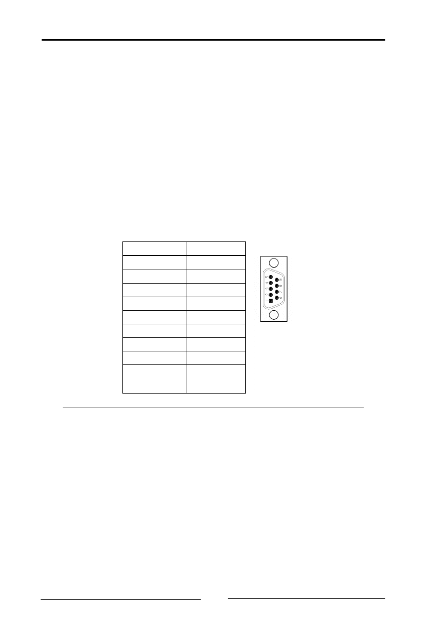
3.1.2.1 USB-to-CAN compact
The USB-to-CAN compact has a bus interface according to ISO 11898-2. The sig-
nals of the bus interface are connected to the 9-pin Sub-D connector (see table 3-
1). The bus interface can be galvanically isolated from the CAN bus as an option.
Pin Nr.
Signal
1
-
2
CAN-Low
3
GND
4
-
5
-
6
-
7
CAN-High
8
-
9
-
Table 3-1: Pin allocation of the Sub-D CAN bus connector
Copyright IXXAT Automation GmbH
USB-to-CAN compact - Manual, V1.6
Connections and displays
7
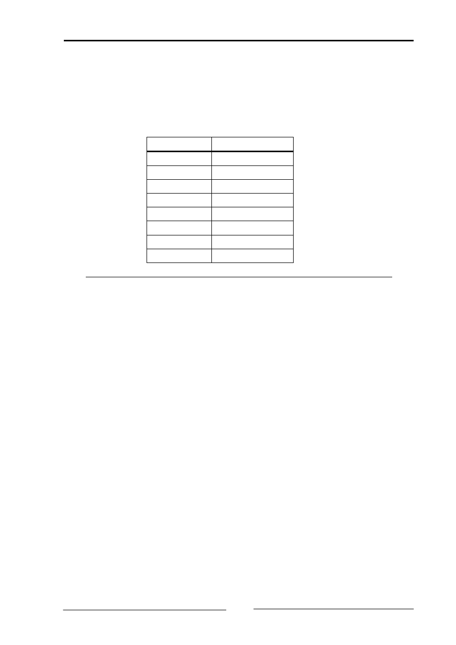
3.1.2.2 USB-to-CAN compact RJ45
The USB-to-CAN compact RJ45 has a bus interface according to ISO 11898-2.
The signals of the bus interface are connected to the 9-pin Sub-D connector (see
table 3-2). The bus interface can be galvanically isolated from the CAN bus as an
option.
Pin Nr.
Signal
1
CAN-High
2
CAN-Low
3
GND
4
-
5
-
6
-
7
GND
8
-
Table 3-2: Pin allocation of the RJ45 CAN bus connector
3.2 Displays
The USB-to-CAN interface has two 2-colored LEDs. One LED is allocated to the
USB bus, the other to the CAN bus.
If the USB LED is lit green, communication with the interface via the USB port is
possible. If communication is not possible, the USB LED is lit red.
The CAN LED flashes green with every message received or transmitted without
error. If the CAN controller is in “Error warning“ or “Error passive“ mode, the LED
flashes red with every message. If the CAN controller is in ”Bus off“ mode, the
LED is permanently lit red.
3.3 CAN bus termination
There is no bus termination resistor for the CAN bus assembled on the USB-to-
CAN compact.

Copyright IXXAT Automation GmbH
USB-to-CAN compact - Manual, V1.6
Appendix
8
4 Appendix
4.1 Support
For more information on our products, FAQ lists and installation tips, please refer
to the support section of our website (
), which also contains
information on current product versions and available updates.
If you have any further questions after studying the information on our website
and the manuals, please contact our support department. The support section on
our website contains the relevant forms for your support request. In order to fa-
cilitate our support work and enable a fast response, please provide precise in-
formation on the individual points and describe your question or problem in de-
tail.
If you would prefer to contact our support department by phone, please also
send a support request via our website first, so that our support department has
the relevant information available.
4.2 Returning hardware
If it is necessary to return hardware to us, please download the relevant RMA
form from our homepage and follow the instructions on this form. In the case of
repairs, please also describe the problem or fault in detail on the RMA form. This
will enable us to carry out the repair quickly.

Copyright IXXAT Automation GmbH
USB-to-CAN compact - Manual, V1.6
Appendix
9
4.3 Technical specifications
USB-Interface:
Version 2.0 (Full Speed)
Microcontroller:
Infineon C161U, 24 MHz
RAM / Flash:
128 kByte / 512 kByte
CAN-Controller:
Philips SJA1000
CAN Transceiver:
Texas Instruments SN65HVD251
ESD-Protection CAN-Bus:
12kV (Human Body Model)
Max. number of CAN Nodes: 120
Galvanic isolation:
1000 V DC between CAN1, CAN2 and internal logic
CAN Signal delay:
with galvanic isolation
typically 50 ns
Housing material:
ABS-plastics
Dimensions:
80 X 45 X 20 mm
Weight:
approx. 100 g
Operating temperature range: 0 - 50°C
Storage temperature range:
-40°C - +85°C
Power supply:
via USB
Power consumption:
typically
250 mA
max.
400 mA
Protection class:
IP40
Relative humidity:
10 – 95 %, non-condensing
Device security:
CSA/UL 60950-00 Class 3862 10, 3862 90
Copyright IXXAT Automation GmbH
USB-to-CAN compact - Manual, V1.6
Appendix
10
4.4 Accessories
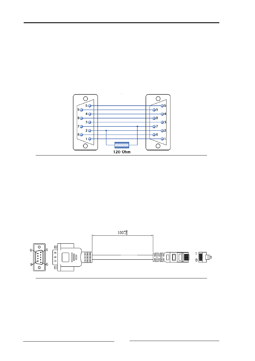
CAN bus termination resistor
For CAN-Bus termination there is a Sub-D9 feed through connector with internal
120 Ohm resistor available.
Ordering number: 1.04.0075.03000
Picture A-1: Connections of the CAN bus termination resistor
Cable adapter RJ45 to Sub-D9M
For the USB-to-CAN compact RJ45 there is an cable adapter RJ45 to Sub-D9M
available. The length of the cable is 100 mm.
Ordering number: 2.09.0000.00952
Picture A-2: Cable adapter RJ45 to Sub-D9M

Copyright IXXAT Automation GmbH
USB-to-CAN compact - Manual, V1.6
Appendix
11
4.5 Note on disposal of used devices
This product is subject to the ElektroG (electrical and electronic
equipment act) and is to be disposed of in accordance with this act.
The products of IXXAT that are subject to the ElektroG are devices
for exclusive commercial use and are marked with the symbol of the
crossed out garbage can.
Based on the B2B regulation, disposal is governed separately in the
Terms of Sale of IXXAT in accordance with § 10 para. 2 clause 3 of the Electrical
and Electronic Equipment Act (ElektroG) in the version of 16.03.2005.
When products supplied by IXXAT are no longer used, the customer is obliged to
dispose these products at his/her own expense. It is to be noted that, unlike pri-
vately used devices (B2C), they may not be disposed of at the collection centers of
public disposal contractors (e.g. municipal recycling centers). The statutory regu-
lations for disposal are to be complied with.
If products delivered were passed on to third parties, the customer is obliged to
take back the delivered products at his/her expense when no longer used and to
correctly dispose of them in accordance with the statutory regulations or to im-
pose these obligations on the third parties.
The Terms of Sale and their supplements as well as further information on the
disposal of used devices can be downloaded from www.ixxat.com.

Copyright IXXAT Automation GmbH
USB-to-CAN compact - Manual, V1.6
Appendix
12
4.6 Declaration of conformity
IXXAT Automation declares
that the product:
USB-to-CAN compact
with the article numbers:
1.01.0087.10100
1.01.0087.10200
and
USB-to-CAN compact RJ45
with the article numbers:
1.01.0088.10100
1.01.0088.10200
do comply with the EC directives 2004/108/EC.
Applied harmonized standards in particular:
EN 55022:2006 + A1:2007
EN 55024:1998 + A1:2001 + A2:2003
23.08.2011, Dipl.-Ing. Christian Schlegel , Managing Director
IXXAT Automation GmbH
Leibnizstrasse 15
88250 Weingarten

Copyright IXXAT Automation GmbH
USB-to-CAN compact - Manual, V1.6
Appendix
13
4.7 FCC Compliance
Declaration of conformity
This device complies with Part 15 of the FCC Rules. Operation is subject to the
following two conditions:
• this device may not cause harmful interference, and
• this device must accept any interference received, including interference that
may cause undesired operation.
Class A digital device instructions:
Note: This equipment has been tested and found to comply with the limits for a
Class A digital device, pursuant to Part 15 of the FCC Rules. These limits are de-
signed to provide reasonable protection against harmful interference when the
equipment is operated in a commercial environment. This equipment generates,
uses, and can radiate radio frequency energy and, if not installed and used in ac-
cordance with the instruction manual, may cause harmful interference to radio
communications. Operation of this equipment in a residential area is likely to
cause harmful interference in which case the user will be required to correct the
interference at his own expense.
Document Outline
Wyszukiwarka
Podobne podstrony:
USB TO RS232 Cable for Windows 2000 user s manual
USB TO RS232 Cable for Windows 2000(Chinese) user s manual
EWD How to Use this Manual
Introduction to Probability Solutions Manual
How To launch a liferaft manually
EWD How to Use this Manual
USB to RS232 for MAC DOC
USB to UART Protocol Converter AVR309 doc2556
be allowed to, let, make, should must have to can could
Quick Digital Thermometer Using Cheap USB to TTL Converter and DS18B20 WITHOUT Arduino or Raspberry
can blocker eis install manual
D&D 3 5 PHB, DMG, & Monster Manual, Update 3 0 to 3 5
Religia i nie tylko, Can, Can - to be able to / móc, potrafić
AudioBox USB Manual
USB driver install manual
więcej podobnych podstron