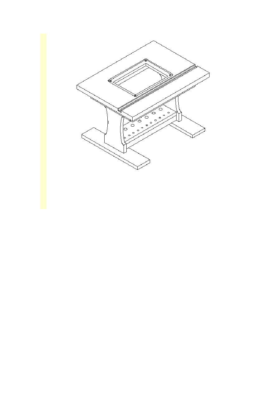
Router table with lift out router table plate
and optional bit organizer.
Router table rear view with EZ mount fence
and optional bit organizer.
This Router Table compares with store bought router tables that sell for over $150.
The one pictured above was made from small pieces of odd and end wood I had in my
junk corner. The top and the sliding fence plates are made from 1" thick countertop
material. I chose counter top material because the plastic laminate provides a low
friction surface for the workpiece to slide over.
You can purchase countertop material from your local home center but if there is a
cabinet shop near you, they may have some sink cutouts they would like to get rid of.
I used an old table top someone was throwing away.
The lift out router plate, miter track, T-Track, knobs, and safety shield were purchased
from Rockler.
This fence design uses my own EZ-Mount clamps. They're easy to make and allow
you to slide the fence on and off without completely removing the knobs. They lock
the fence down as securely as the traditional design with slots in the table top.
This project makes extensive use of pocket hole joints. The joints are designed so the
pocket holes are hidden after assembly. Pocket holes are the easiest way to make
strong and accurate joints in wood. If you haven't been using pocket holes before,
you'll wish you had started using them long ago.
Materials List
Qty
Item
Material
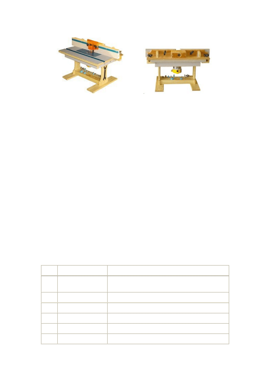
1
Top
16" By 22" using Countertop material with plastic
laminate coating.
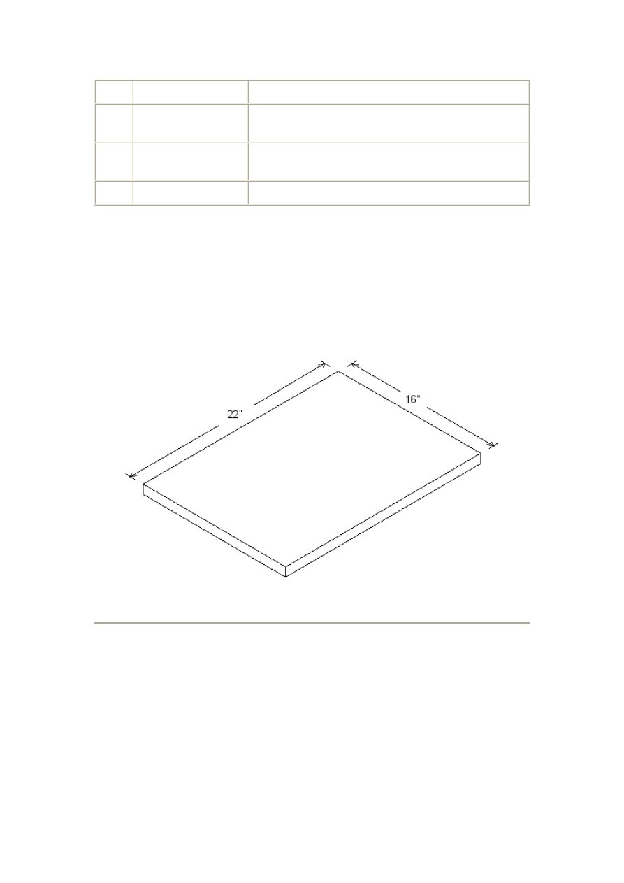
2
Front & Back
18" by 2 1/4" using 3/4" stock
2
Ends
10 1/2" by 2 1/4" using 3/4" stock
1
Front Stiffener
15" by 2 3/4" using 3/4" stock
1
Rear Stiffener
16 1/2" by 1 1/4" using 3/4" stock
2
Legs
12" by 5 1/2" using 3/4" stock
2
Feet
16" by 3 1/2" using 3/4" stock
1
Router Table Plate
8" by 11" by 1/4" thick aluminum plate
1
Miter Guage Track
22" by 1" by 1/2" thick aluminum miter guage track
1
Bit Safety Guard
Router Table Drawings
Please read and follow all tool manufacturers safety and operating instructions before
operating equipment. Always wear eye and hearing protection.
Top
16" by 22" Countertop Material
Front & Back Pieces
(2 Required)
18" by 2 1/4" using 3/4" stock
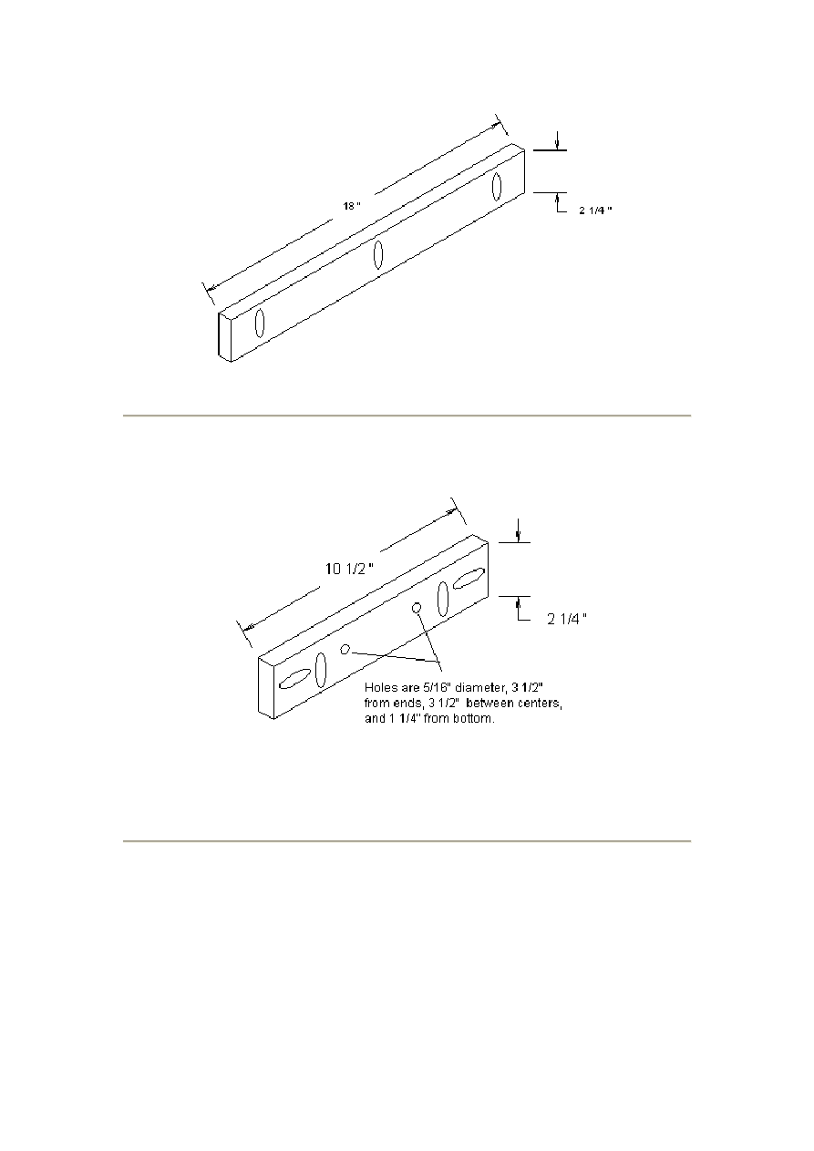
Ends
2 (Required)
10 1/2" by 2 1/4" using 3/4" stock
The end pieces require two 5/16" diameter holes. This allows for a little bit of
adjustment when mounting the legs so the bottom will sit flat on the work table.
Front Stiffener
2 (Required)
15" by 2 3/4" using 3/4" stock
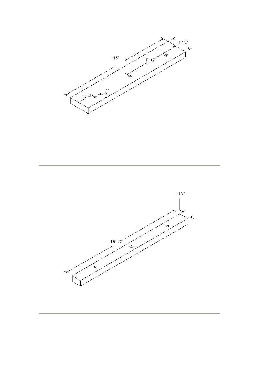
This peice requires three screw holes for mounting the stiffener to the underside of the
top. They are shown as countersunk holes but you could just as well use pan head
screws. The stiffeners provide extra strength to keep the router table surface flat and
provide extra thickness of material for the miter track screws. Note that the screw
holes are on inch from the edge. This is so the screws don't hit the miter guage track.
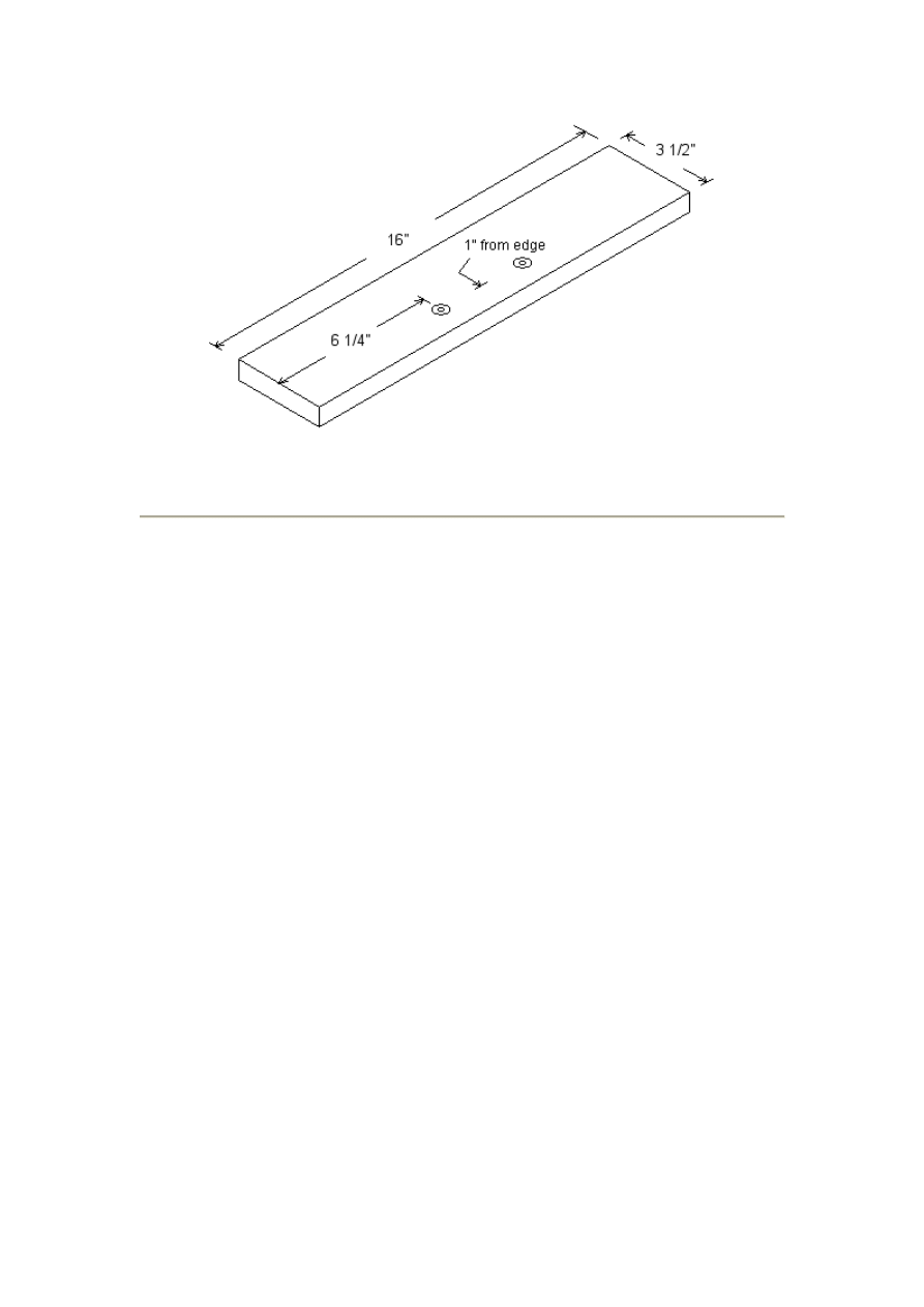
Rear Stiffener
2 (Required)
16 1/2" by 1 1/4" using 3/4" stock
The rear stiffener also requires three screw holes but the location is not critical.
Legs
2 (Required)
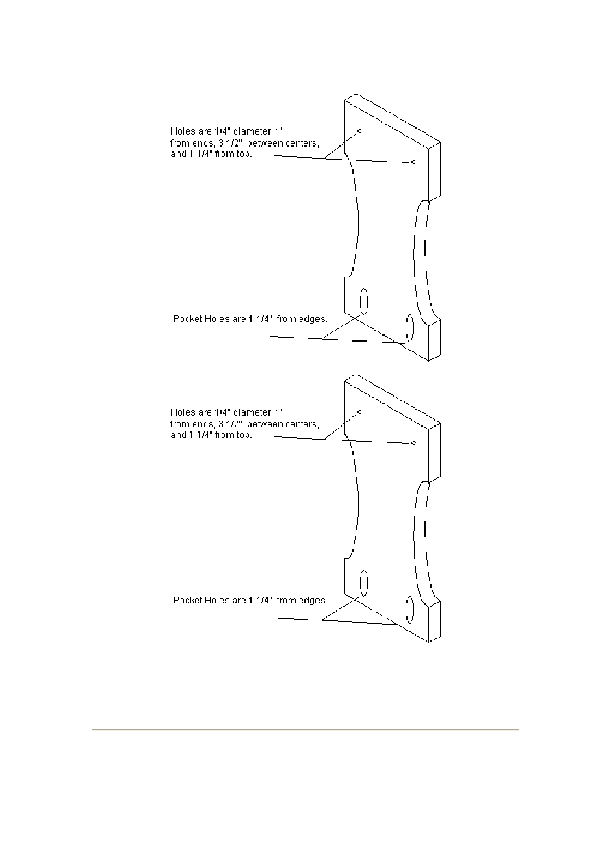
12" by 5 1/2" using 3/4" stock
The legs need two 1/4" diameter holes at the top for mounting them to the ends. The
two pocket holes on the bottom are for mounting the legs to the feet. As usual, the
location of the pocket holes is not critical.
Feet
2 (Required)
16" by 3 1/2" using 3/4" stock
The two screw holes in the feet are for attaching the optional bit organizer.
Leg Layout Grid
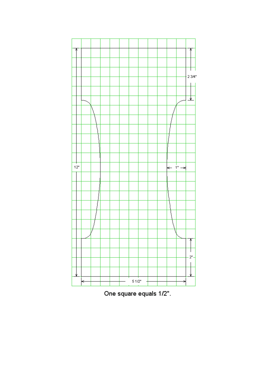
The curved cutouts on the sides of the legs aren't necessary but I thought they added a
little to the style of the router table. You can use the above grid to draw the curves on
your workpiece.
Router Table Instructions
Please read and follow all tool manufacturers safety and operating instructions before
operating equipment. Always wear eye and hearing protection.
Router Plate Cutout Dimensions
To cut out the recess for the router plate, you can make a frame to guide your router
as shown in Figure 1 below. You'll need a 3/4" wide straight bit for this.
To determine the dimensions of the frame, put a 3/4" straight bit in your router and set
the depth to about 1/8". (Just deep enough to make a measurement.) Clamp a straight
edge to a piece of scrap stock and cut a 3/4" slot with your router as shown in Figure
2. Measure the distance from the slot to the edge guide. Lets call this distance
"X"
.
This is the distance of the edge of your router base to the edge of the bit.
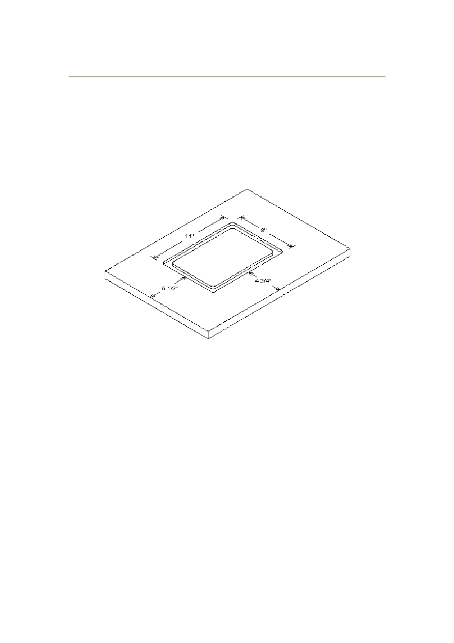
Since the router plate cutout needs to be 8" by 11", the height of the frame should be
8" plus two times the distance
"X"
and the width of the frame should be 11" plus two
times distance
"X"
. For my router, the inside dimensions of this frame turned out to
be a little more than13" by 16". But your router may be different so be sure to get the
exact measurement and make your frame accordingly. I recommend you practice on
some scrap material before making the cut on your good countertop material.
You can assemble the frame with pocket holes as shown in Figure 1.
When your frame is finished and you're sure it will result in the proper size cutout,
clamp it to the countertop material so the cutout will be centered side to side and the
front of the cutout will be 4 3/4" from the front edge of the material. This allows room
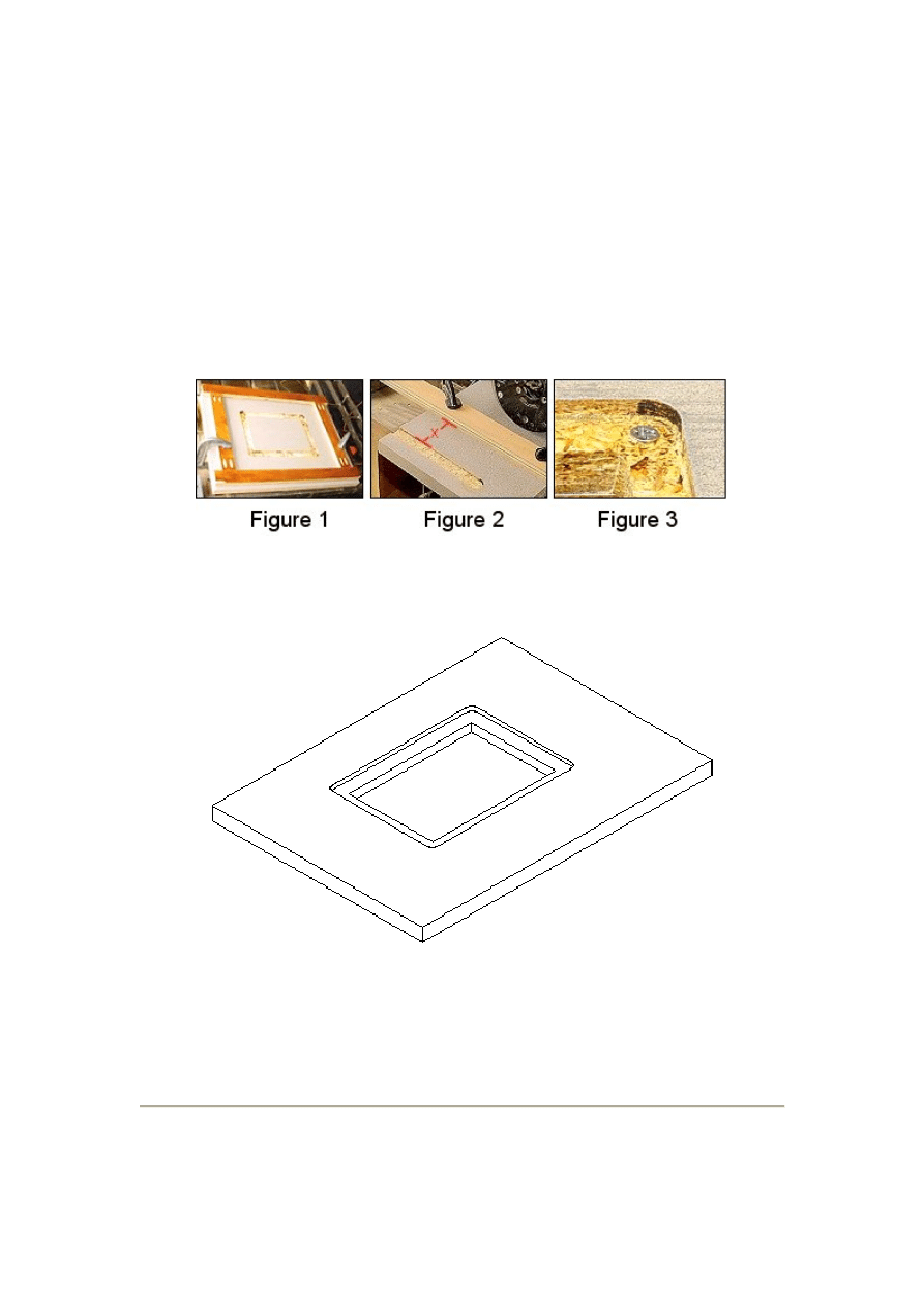
for the miter guage slot.
You should set the router to cut a slot about 5/16" deep. (The router plate is 1/4" thick
but you need to have the recess a little deeper so you can set it to be flush with the
table surface. You do this by putting a flathead screw in each corner as shown in
Figure 3. Then, you can adjust the screw height so the plate is flush with the top on all
four corners.
Be sure the frame and workpiece are securely clamped to a solid
work table or workbench and follow all safety precautions that came with
your router. Never use power tools without safety glasses and don't wear
loose clothing. Your clothing can get caught up in moving parts with any
type of power tool.
Router Plate Cutout Step 2
You can remove the center of the cutout with a jig saw. Try to leave as much material
around the edge as possible. If your jig saw blade makes a1/16" wide cut, the recess
should have about an 11/16" wide edge around it. Wait until the stiffeners are
installed before putting the corner adjustment screws in place.
Slot for the Miter Guage
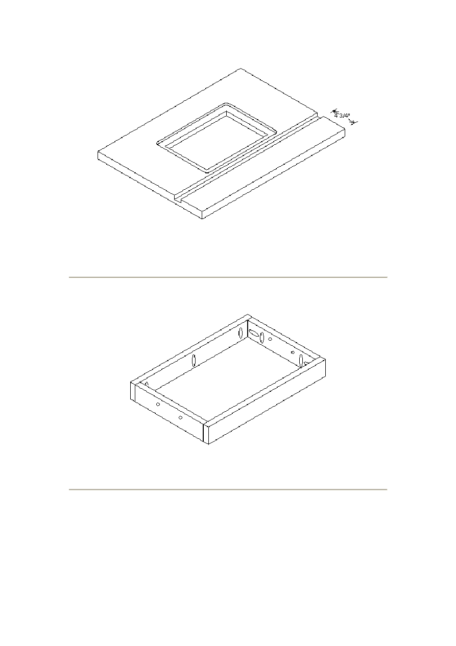
Cut a slot 1" wide by 1/2" deep and 4 3/4" from the front edge as shown above. You
can use either your table saw or router for this cut.
Assemble the Sides
Assemble the four sides with a pocket hole screw in each corner as shown above.
Attach Side Assembly to Top
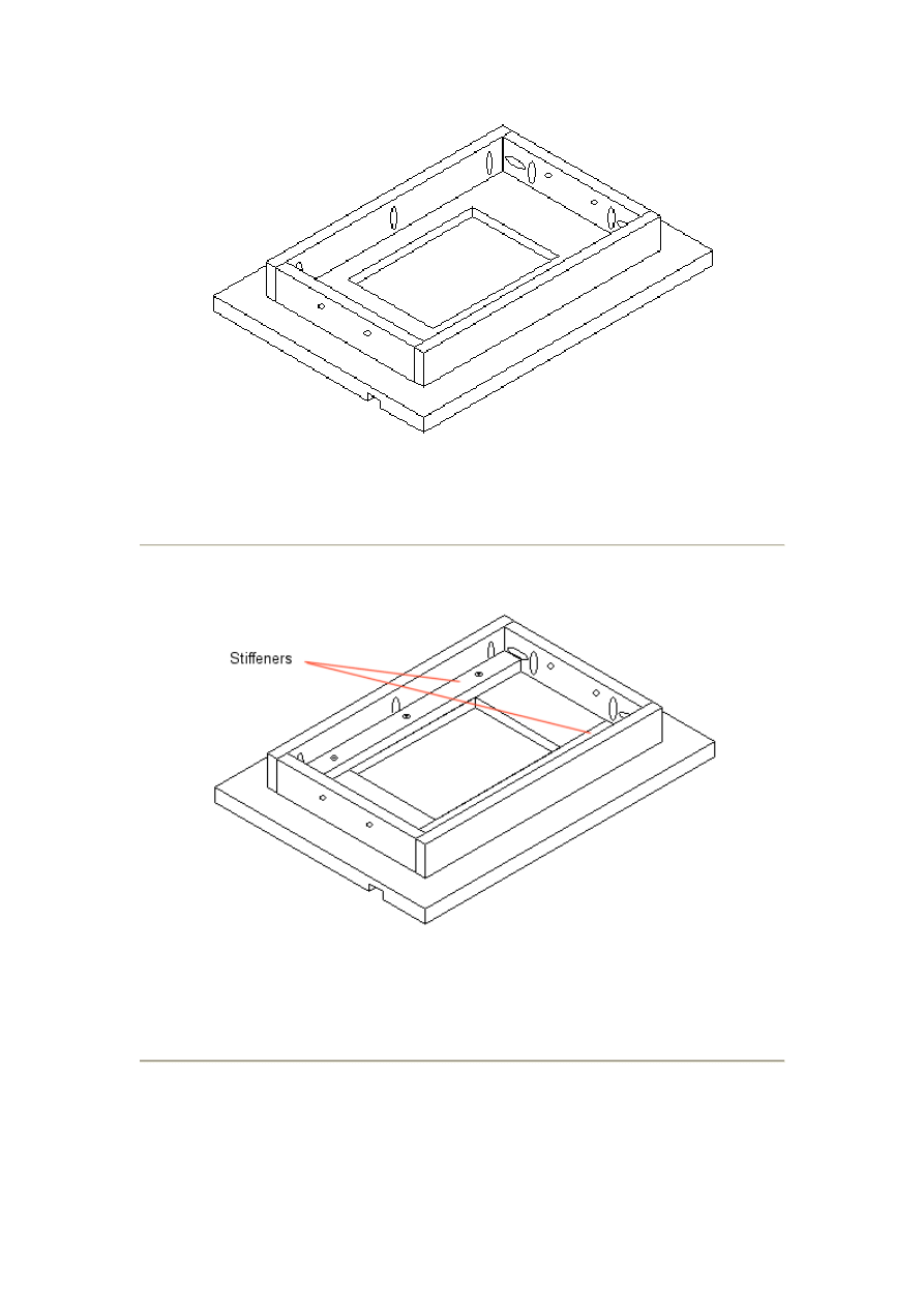
Attach the assembled sides to the underside of the top with pocket hole screws as
shown above. It should be centered from front to back and side to side.
Attach Stiffeners to Top
Attach the two stiffeners to the underside of the top as shown above. Note that the
front stiffener is shorter and wider than the rear one. The front one needs to be
centered side to side so the legs have room to fit. See the next drawing.
Attach legs
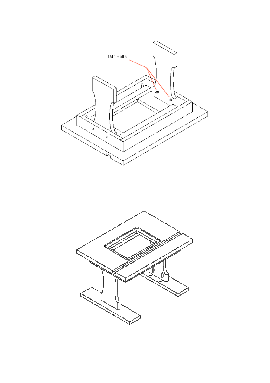
Attach the legs with two 1/4" by 2" bolts as shown. You can use carriage bolts for this
if you like. The holes in the sides are a little larger and this gives you some movement
in the legs to ensure they sit flat on the worktable.
Attach Legs to the Feet
Attach the legs to the feet with pocket hole screws as shown. The legs should be
centered from side to side and end to end of the feet. If you are including the bit
organizer, be sure the holes for the bit organizer are on the inside of the legs.
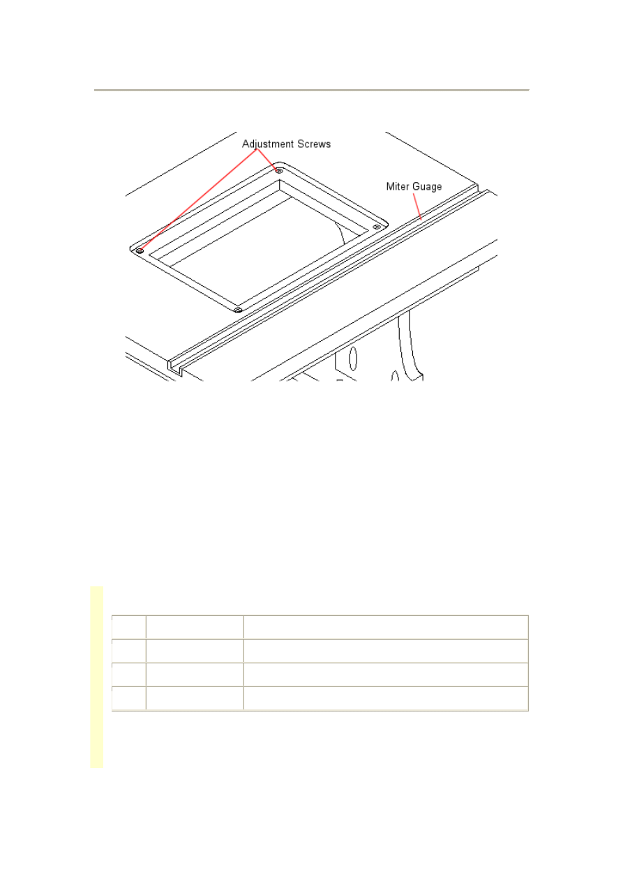
Attach the Adjustment Screws and Miter Guage
Predrill a hole in each corner of the cutout and install the adjustment screws as shown
above. Next, install the miter guage with flathead screws as shown above.
Now, you need to adjust the screws so the router plate sits flush with the surface of
the table top.
Router Bit Organizer Plans
Please read and follow all tool manufacturers safety and operating instructions before
operating equipment.
Always wear eye and hearing protection.
Materials List
Qty Item
Material
1
Top
15" By 4 1/4" using 3/4" stock
1
Bottom
15" by 2 3/4" using 3/4" stock
2
Sides
15" by 1 1/4" using 3/4" stock
Bit Organizer Parts Dimensions
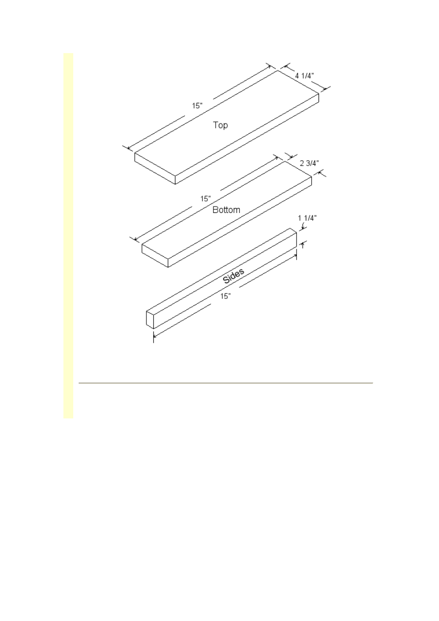
Cut the top, bottom, and 2 sides from 3/4" stock as shown above.
Drill the Holes
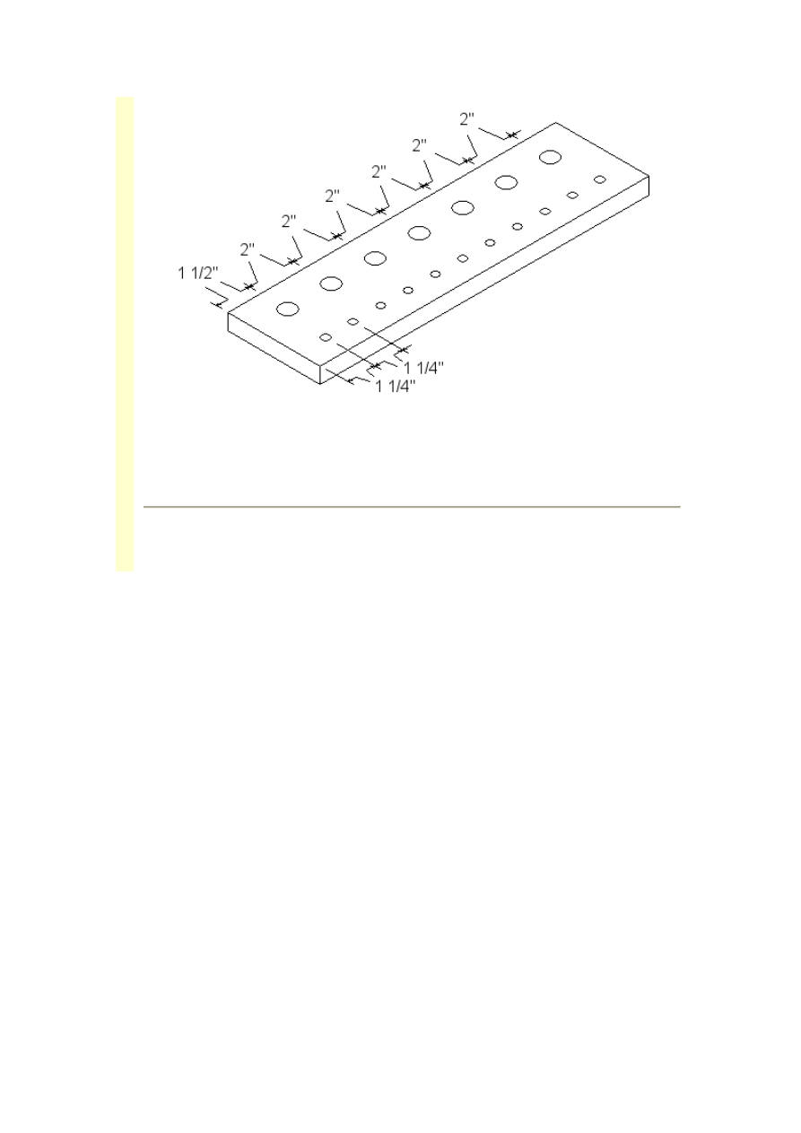
Drill seven 9/16" holes along one edge of the top as shown. Then, drill eleven
9/32" holes along the other edge as shown. This will accomodate seven bits with
1/2" shanks and eleven bits with 1/4" shanks.
Assemble the Bit Organizer
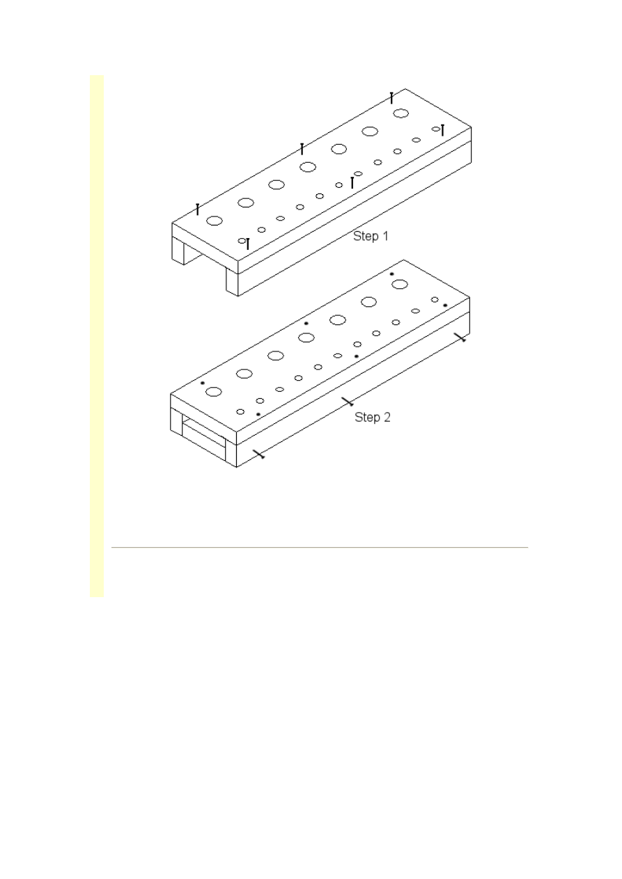
Attach the top to the sides with 1 1/2" long finishing nails as shown. Then insert
the bottom between the sides as shown and attach with finishing nails.
Attach the Bit Organizer to the Router Table
You should already have two holes in each router table foot for attaching the bit
organizer. Attach the finished bit organizer to the feet using two flathead screws
from the bottom of each foot.
Wyszukiwarka
Podobne podstrony:
2 Woodworking Plans Standing Router Table
Router Table Fence Plans
Amateur Woodworker Router Table
Router Portable Router Station Plans
Router Table mate
Router Table 2
Router Table Fence Jeff Greef Woodworking
woodwork dewalt router table tips construction (4 pgs)
Professional Router Table
Quick and Easy Router Table
Bench Top Router Table Jeff Greef Woodworking
Router Table
CNC ROUTER PLANS 5
CNC ROUTER PLANS 4
Ottoman Coffe Table & Ottoman Plans
CNC ROUTER PLANS 2
(Ebooks) DIY Woodwork Plans Drill Press Table
CNC ROUTER PLANS 1
więcej podobnych podstron