
Eaton Corporation
Eaton ist ein führendes Energie-
Management-Unternehmen. Weltweit
ist Eaton mit Produkten, Systemen und
Dienstleistungen in den Bereichen Electrical,
Hydraulics, Aerospace, Truck und
Automotive tätig.
Eatons Electrical Sector
Eatons Electrical Sector ist weltweit führend
bei Produkten, Systemen und Dienstleistungen
zu Energieverteilung, sicherer Stromversorgung
und Automatisierung in der Industrie, in Wohn- und
Zweckbauten, öffentlichen Einrichtungen, bei Energie-
versorgern, im Handel und bei OEMs.
Zu Eatons Electrical Sector gehören
die Marken Cutler-Hammer®, Moeller®,
Micro Innovation, Powerware®, Holec®,
MEM® und Santak®.
www.eaton.com
01/11 MN03402002Z-DE/EN
ersetzt/replaces 05/02 AWB1210-1457D/GB
Handbuch/Manual
PKZM4/
XT
PR…DC1
Motorschutzschalter PKZM4/XTPR…DC1
Überlastüberwachung von Ex e-Motoren
PKZM4/XTPR…DC1 motor-protective circuit-breaker
Overload monitoring of Ex e motors
Eaton Corporation
Eaton is a leading power
management company. Eaton
operates worldwide with products,
systems and services in the
electrical, hydraulic, aerospace,
truck and automotive sectors.
Eatons Electrical Sector
Eatons Electrical Sector is the
worldwide leader in products,
systems and services for energy
distribution, safe electricity supply
and automation in industrial,
residential and purpose-built
buildings, public facilities, energy
providers, commerce and OEMs.
Eaton Electrical Sector includes the
brands Cutler-Hammer®, Moeller®,
Micro Innovation, Powerware®,
Holec®, MEM® and Santak®
www.eaton.com
Eaton addresses worldwide:
www.moeller.net/address
E-Mail: info-bonn@eaton.com
Internet: www.eaton.com/moellerproducts
www.eaton.com
Herausgeber/Issued by: Eaton Industries GmbH
Hein-Moeller-Str. 7–11
D-53115 Bonn
© 2002 by Eaton Industries GmbH
Änderungen vorbehalten/Subject to alteration
MN03402002Z-DE/EN Doku/Doku/Eb 01/11
Printed in Germany (02/11)
Artikel-Nr./Article No.: 151985
4 *patpka#v,mccx*
Rückenbreite 2 mm
(1 Blatt = 0,080 mm für Eberwein Digitaldruck bei 80 g/m
2
)

Alle Marken- und Produktnamen sind Warenzeichen oder eingetragene
Warenzeichen der jeweiligen Titelhalter.
1. Auflage 2002, Redaktionsdatum 05/02,
2. Auflage 2011, Redaktionsdatum 01/11
Siehe Änderungsprotokoll im Kapitel „Zu diesem Handbuch“.
© 2004 by Eaton Industries GmbH, 53105 Bonn
Autor:
Wolfgang Nitschky, Dirk Meyer
Redaktion: Heidrun Riege, René Wiegand
Alle Rechte, auch die der Übersetzung, vorbehalten.
Kein Teil dieses Handbuches darf in irgendeiner Form (Druck, Fotokopie,
Mikrofilm oder einem anderen Verfahren) ohne schriftliche Zustimmung
der Firma Eaton Industries GmbH, Bonn, reproduziert oder unter
Verwendung elektronischer Systeme verarbeitet, vervielfältigt oder
verbreitet werden.
Änderungen vorbehalten.
Gedruckt auf Papier aus chlor- und säurefrei gebleichtem Zellstoff.
All brand and product names are trademarks or registered trademarks of
the owner concerned.
1
st
published 2002, edition date 05/02,
2
nd
edition 01/11
See revision protocol in the “About this manual“ chapter.
© 2004 by Eaton Industries GmbH, 53105 Bonn
Author:
Wolfgang Nitschky, Dirk Meyer
Editor:
Heidrun Riege, René Wiegand
Translator: globaldocs
All rights reserved, including those of the translation.
No part of this manual may be reproduced in any form (printed,
photocopy, microfilm or any otherprocess) or processed, duplicated or
distributed by means of electronic systems without written permission
of Eaton Industries GmbH, Bonn.
Subject to alterations without notice.
Printed on bleached cellulose. 100 % free from chlorine and acid.
Rückenbreite 2 mm
(1 Blatt = 0,080 mm für Eberwein Digitaldruck bei 80 g/m
2
)

I
Vor Beginn der Installationsarbeiten
• Gerät spannungsfrei schalten
• Gegen Wiedereinschalten sichern
• Spannungsfreiheit feststellen
• Erden und kurzschließen
• Benachbarte, unter Spannung stehende
Teile abdecken oder abschranken.
• Die für das Gerät angegebenen Montage-
hinweise (AWA/IL) sind zu beachten.
• Nur entsprechend qualifiziertes Personal
gemäß EN 50110-1/-2 (VDE 0105
Teil 100) darf Eingriffe an diesem
Gerät/System vornehmen.
• Achten Sie bei Installationsarbeiten darauf,
dass Sie sich statisch entladen, bevor Sie
das Gerät berühren.
• Schwankungen bzw. Abweichungen der
Netzspannung vom Nennwert dürfen die in
den technischen Daten angegebenen Tole-
ranzgrenzen nicht überschreiten, andern-
falls sind Funktionsausfälle und Gefahren-
zustände nicht auszuschließen.
• Einbaugeräte für Gehäuse oder Schränke
dürfen nur im eingebauten Zustand
betrieben und bedient werden.
Before commencing the installation
• Disconnect the power supply of the device.
• Ensure relosing interlock that devices
cannot be accidentally restarted.
• Verify isolation from the supply.
• Connect to earth and short-circuit.
• Cover or fence off neighbouring live parts.
• Follow the installation instructions
(AWA/IL) included with the device.
• Only suitably qualified personnel in
accordance with EN 50110-1/-2
(VDE 0105 Part 100) may work on this
device/system.
• Before installation and before touching
the device ensure that you are free of
electrostatic charge.
• The rated value of the mains voltage may
not fluctuate or deviate by more than the
tolerance specified, otherwise malfunction
and hazardous states are to be expected.
• Panel-mount devices may only be operated
when properly installed in the cubicle or
control cabinet.
Eato
n In
dust
ries
GmbH
Sich
erheits
hinw
eise/Safety i
nstru
ctio
ns
Gefahr!
Gefährliche
elektrische
Spannung!
Danger!
Dangerous
electrical
voltage!

II
01/11 MN03402002Z-DE/EN
Motorschutzschalter PKZM4/XTPR…DC1
Überlastüberwachung von Ex e-Motoren
PKZM4/XTPR…DC1 motor-protective circuit-breaker
Overload monitoring of Ex e motors
Anhang/Appendix
Überblick/Overview

1
01/11 MN03402002Z-DE/EN
Motorschutzschalter
PKZM4/XTPR…DC1
5
– Überlastschutz mit Motorschutzschaltern
– Strombereiche der Motorschutzschalter
– Temperaturkompensation 7
– Phasenausfall 7
– Wiedereinschaltung 9
– Testfunktion 9
Überlastüberwachung von Ex e-Motoren
Einstellung der Überstromschutzeinrichtung
Kurzschluss-Schutz bei Motorschutzschaltern
Inhalt

Inhalt
2
01/11 MN03402002Z-DE/EN
Typenschild/Rating plate PKZM4/XTPR…01
Auslösekennlinien/Tripping characteristics
PKZM4/XTPR…DC1
– PKZM4-16/XTPR016DC1 42
– PKZM4-25/XTPR025DC1 43
– PKZM4-32/XTPR032DC1 44
– PKZM4-40/XTPR040DC1 45
– PKZM4-50/XTPR050DC1 46
– PKZM4-58/XTPR058DC1 47
– PKZM4-63/XTPR063DC1 48
EG-Konformitätserklärung/Declaration of
CE Conformity (Doc. No.: K 000411)
3
01/11 MN03402002Z-DE/EN
Zu diesem Handbuch
Das vorliegende Handbuch gilt für Motorschutzschalter
PKZM4/XTPR…DC1.
Dieses Handbuch beschreibt die Überlastüberwachung zum
Schutz von Motoren in explosiongefährdeten Bereichen
(Ex e-Bereichen).
Zielgruppe
Dieses Handbuch richtet sich an Fachpersonal, das den
Motorschutzschalter installiert, in Betrieb nimmt und wartet.
Abkürzungen und Symbole In diesem Handbuch werden Abkürzungen und Symbole
eingesetzt, die folgende Bedeutung haben:
X
zeigt Handlungsanweisungen an
Ex e
Zündschutzart „Erhöhte Sicherheit“
PTB
Physikalisch Technische Bundesanstalt,
Zertifizierungsstelle für Geräte im Ex e-Bereich
NM
Niedrigster möglicher Einstellstrom
HM
Höchster möglicher Einstellstrom
h
macht Sie aufmerksam auf interessante Tipps und
Zusatzinformationen
h
Achtung!
warnt vor leichten Sachschäden.
j
Gefahr!
warnt vor schweren Sachschäden und schweren
Verletzungen oder Tod.

Zu diesem Handbuch
4
01/11 MN03402002Z-DE/EN
Für eine gute Übersichtlichkeit finden Sie auf den linken
Seiten im Kopf die Kapitelüberschrift und auf den rechten
Seiten den aktuellen Abschnitt, Ausnahmen sind Kapitel-
anfangsseiten und leere Seiten am Kapitelende.
Änderungsprotokoll
Das Handbuch AWB1210-1457D/GB ist ab der Ausgabe mit
Redaktionsdatum 01/11 umbenannt in
MN03402002Z-DE/EN.
Gegenüber der letzten Ausgabe haben sich folgende
wesentliche Änderungen ergeben:
Redaktions-
datum
Seite
Stichwort
neu
geän-
dert
ent-
fällt
01/11
allg.
Aufnahme der Eaton-Typen
j
allg.
EEx e (jetzt: Ex e)
j
EG-Baumusterprüfbescheinigungs-
Nummer
j
Typenschild/Rating plate
j
EG-Konformitätserklärung/
Declaration of CE Conformity
j
05/02
–
–
–
–
–

5
01/11 MN03402002Z-DE/EN
1
Motorschutzschalter
PKZM4/XTPR…DC1
Vorwort
Für den Schutz von Motoren in explosionsgefährdeten
Bereichen gelten zusätzlich zu den Vorschriften nach
EN 60079-14 und VDE 0165 Teil 1 separate Vorschriften für
die entsprechenden Zündschutzarten. Für Motoren in der
Zündschutzart „e“ „Erhöhte Sicherheit“ verlangt die
Vorschrift EN 50019 zusätzliche Maßnahmen. Durch diese
werden mit einem erhöhten Grad an Sicherheit die Möglich-
keiten von unzulässig hohen Temperaturen und das
Entstehen von Funken und Lichtbögen an Motoren, bei
denen dies im normalen Betrieb nicht auftritt, verhindert.
Die Motorschutzgeräte hierfür, die sich selber nicht im
Ex e-Bereich befinden, müssen durch eine akkreditierte
Zulassungsstelle zertifiziert sein.
Die Richtlinie 94/9/EG (ATEX 100a) zur Angleichung der
Rechtsvorschriften der Mitgliedsstaaten für Geräte und
Schutzsysteme zur bestimmungsmäßigen Verwendung in
explosionsgefährdeten Bereichen ist ab dem 30.06.2003
bindend.
Das Motorschutzsystem PKZM4/XTPR…DC1 ist nach der
Richtlinie 94/9/EG (ATEX 100a) durch die PTB zugelassen.
h
Die EG-Baumusterprüfbescheinigungs-Nummer lautet:
PTB 10 ATEX 3012.
((
Motorschutzschalter
PKZM4/XTPR…DC1
6
01/11 MN03402002Z-DE/EN
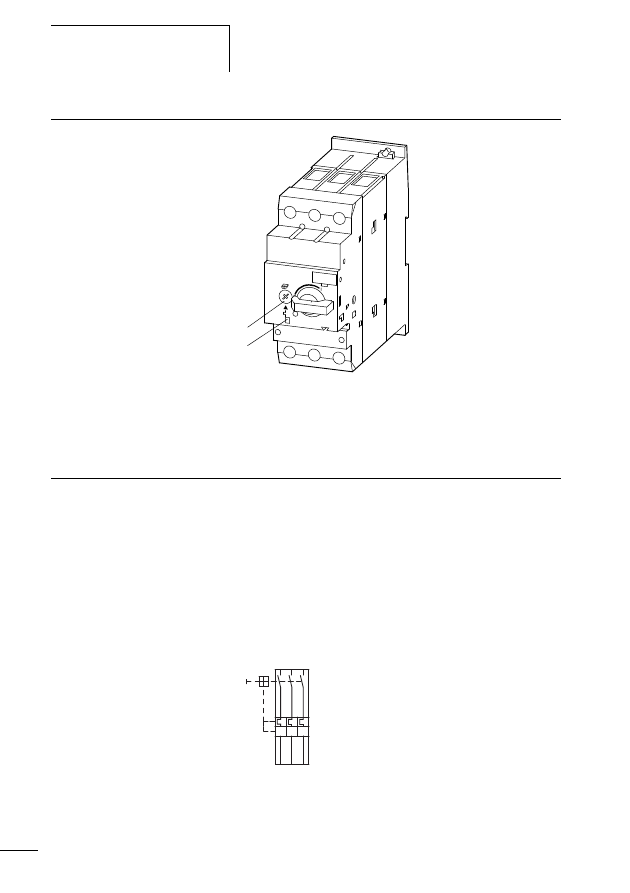
Geräteübersicht
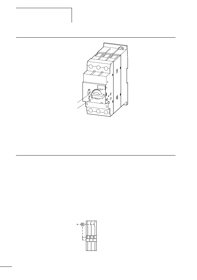
Abbildung 1: Motorschutzschalter PKZM4/XTPR…DC1
a Stromeinstellscheibe Motornennstrom
b Testeinrichtung
Gerätebeschreibung
Überlastschutz mit Motorschutzschaltern
Die Motorschutzschalter PKZM4/XTPR…DC1 sind dreipolige
elektromechanische Motorschutzschalter mit Bimetallen zur
Überlastüberwachung.
Bei einer Überlastauslösung schaltet der Schalter
PKZM4/XTPR…DC1 allpolig den Hauptstromkreis ab.
Somit wird der Stromfluss des zu überwachenden Motors
direkt abgeschaltet. (a nachfolgende Abb. 2)
Abbildung 2: Schaltbild Motorschutzschalter PKZM4/XTPR…DC1
a
b
I > I > I >
L1 L2
L3
T1 T2 T3
-Q1
Gerätebeschreibung
7
01/11 MN03402002Z-DE/EN
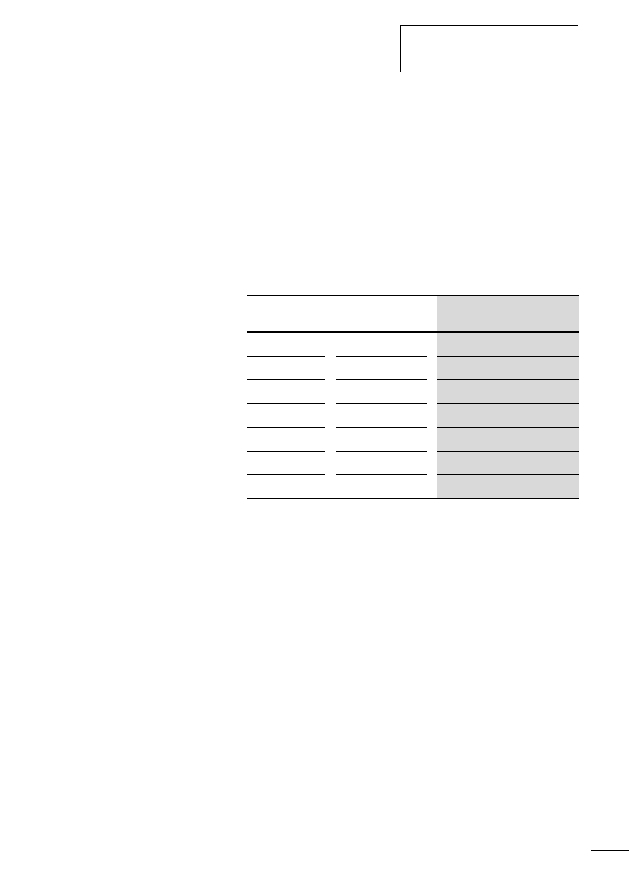
Strombereiche der Motorschutzschalter
PKZM4/XTPR…DC1
Die PKZM4/XTPR…DC1 werden mit Hilfe der Stromeinstell-
scheibe a (a Abb. 1 auf Seite 6) auf den Motornennstrom
eingestellt.
Mit sieben verschiedenen Typen können Motoren von 10 bis
63 A Motornennstrom überwacht werden (a Tabelle 1).
Tabelle 1:
Strombereiche der
PKZM4/XTPR…DC1
Temperaturkompensation
Zwei Parameter beeinflussen die Ausbiegung der Bimetalle.
Zum einen ist das die Wärme, die proportional zum
fließendem Strom erzeugt wird, und zum anderen ist das der
Einfluss der Umgebungstemperatur. Der Einfluss der
Umgebungstemperatur wird mit Hilfe eines zusätzlichen
Bimetalls, das nicht vom Motorstrom durchflossen wird, im
Temperaturbereich von -5 bis +55 °C kontinuierlich durch
Korrektur des Auslöseweges selbsttätig kompensiert.
Phasenausfall
Motorschutzschalter PKZM4/XTPR…DC1 sind phasenaus-
fallempfindlich. Die Auslenkung aller drei Bimetalle wirkt auf
eine Auslösebrücke, die bei Erreichen des Grenzwertes einen
Typ
Strombereich I
e
[A]
PKZM4-16
XTPR016DC1
10 - 16
PKZM4-25
XTPR025DC1
16 - 25
PKZM4-32
XTPR032DC1
24 - 32
PKZM4-40
XTPR040DC1
32 - 40
PKZM4-50
XTPR050DC1
40 - 50
PKZM4-58
XTPR058DC1
50 - 58
PKZM4-63
XTPR063DC1
55 - 63
Motorschutzschalter
PKZM4/XTPR…DC1
8
01/11 MN03402002Z-DE/EN
Sprungschalter umschaltet. Gleichzeitig verschieben alle drei
Bimetalle die Differenzialbrücke. Wird bei einem Phasen-
ausfall ein Bimetall weniger ausgelenkt, bleibt die Differen-
zialbrücke zurück und der Weg wird in zusätzlichen
Auslöseweg umgewandelt, so dass es zu einer vorzeitigen
Auslösung kommt.
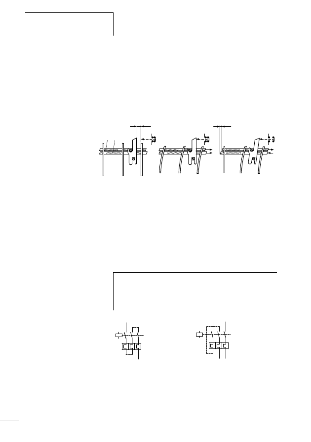
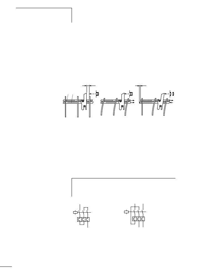
Abbildung 3: Funktion der Phasenausfallempfindlichkeit mit Hilfe
einer Auslöse- und Differenzialbrücke
a Auslösebrücke
b Differenzialbrücke
c Abstand
d Differenzweg
Abbildung 4: Verdrahtung des Motorschutzschalters für den
Schutz von Wechselstrom- oder Gleichstrommo-
toren (Reihenschaltung der Bimetallauslöser)
(a Abschnitt „Auslösekennlinien/Tripping characteristics
PKZM4/XTPR…DC1“ auf Seite 41)
ab
c
d
e
f
g
ON
ON
OFF
dreiphasige
Überlast
Normalbetrieb
ungestört
Ausfall einer Phase
(zweiphasige Belastung)
h
Soll mit dem PKZM4/XTPR…DC1 ein Wechselstrommotor
oder ein Gleichstrommotor überwacht werden, muss der
Strom über alle drei Strombahnen geführt werden, um
Frühauslösungen zu vermeiden.

Gerätebeschreibung
9
01/11 MN03402002Z-DE/EN
Wiedereinschaltung
Nach einer Auslösung müssen zunächst die Bimetalle
abkühlen, bevor der Motorschutzschalter wieder einge-
schaltet werden kann.
Testfunktion
Durch eine zusätzliche Testeinrichtung b (a Abb. 1 auf
Seite 6) kann die Funktionstüchtigkeit des Schalters kontrol-
liert werden.
Das Betätigen der Testeinrichtung des eingeschalteten
PKZM4/XTPR…DC1 mittels eines Schraubendrehers führt
zur Auslösung des Motorschutzschalters. Somit kann bei der
Inbetriebnahme die einwandfreie Funktion des Motorschutz-
schalters getestet werden.
h
Beim Motorschutzschalter PKZM4/XTPR…DC1 ist nur
eine manuelle Wiedereinschaltung vor Ort möglich.

10
01/11 MN03402002Z-DE/EN

11
01/11 MN03402002Z-DE/EN
2
Projektierung
Überlastüberwachung von
Ex e-Motoren
Durch besondere konstruktive Maßnahmen erreicht man bei
Motoren die Zündschutzart Ex e. Die Motoren werden auf
Basis der höchstzulässigen Oberflächentemperaturen
Temperaturklassen zugeordnet. Zusätzlich wird die Erwär-
mungszeit t
E
und das Verhältnis Anlaufstrom zu Nennstrom
I
A
/I
N
bestimmt und auf dem Motor angegeben.
Die Erwärmungszeit t
E
ist die Zeit, in der sich eine Wicklung
bei Anlaufstrom I
A
von der Endtemperatur im Bemessungs-
betrieb zur Grenztemperatur erwärmt.
Ex e-Motoren für sich alleine sind jedoch noch nicht sicher.
Sie erlangen die Explosionssicherheit erst durch zusätzliche
Maßnahmen bei der Installation durch zweckentsprechende
Auswahl und Einsatzbedingungen (PTB-Prüfregeln), unter
anderem durch das Zusammenschalten mit einer richtig
bemessenen und eingestellten Überstromschutzeinrichtung.
Einstellung der Über-
stromschutzeinrichtung
j
Gefahr!
Die stromabhängige Schutzeinrichtung muss so ausge-
wählt werden, dass nicht nur der Motorstrom überwacht
wird, sondern auch der festgebremste Motor innerhalb der
Erwärmungszeit t
E
abgeschaltet wird.
Dies bedeutet:
Das Schutzorgan ist so zu bemessen, dass die Auslösezeit
t
A
für das Verhältnis I
A
/I
N
des Ex e-Motors nach Kennlinie
nicht größer als seine Erwärmungszeit t
E
ist, um den
Motor innerhalb dieser Zeit sicher abzuschalten
(a nachfolgendes Beispiel).
Projektierung
12
01/11 MN03402002Z-DE/EN
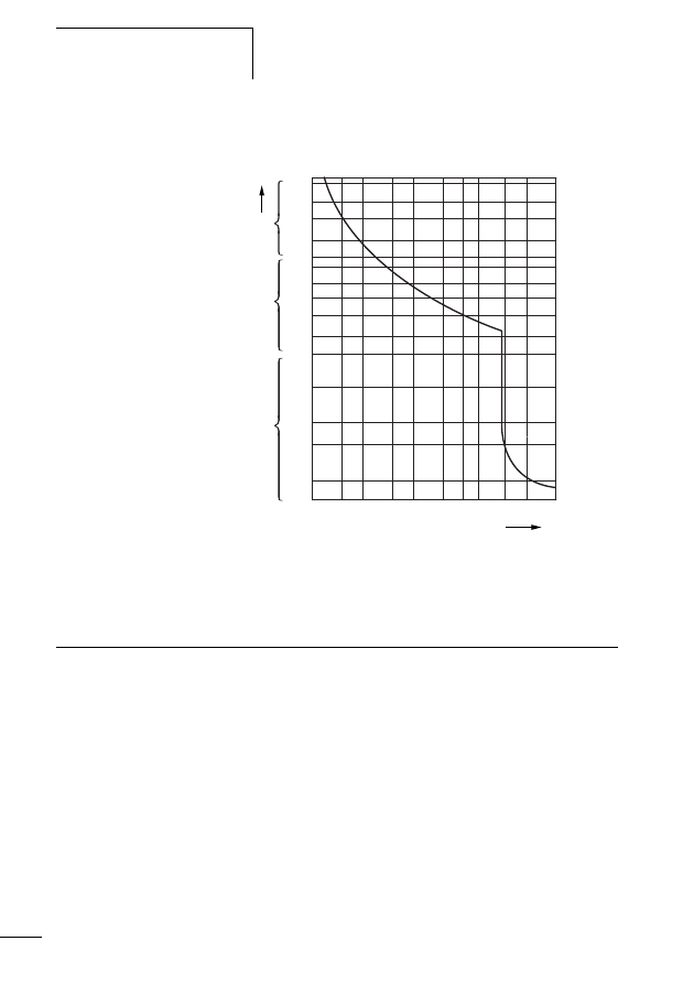
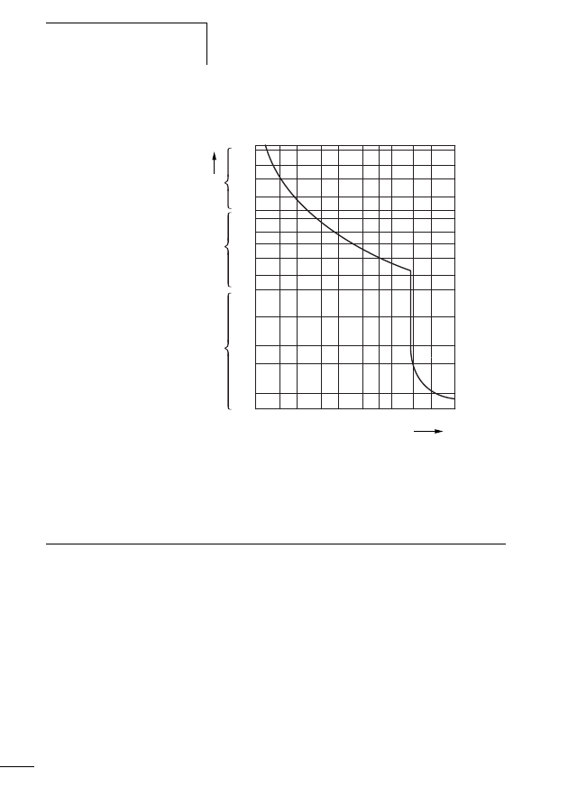
Beispiel: I
A
/I
N
= 6, t
E
= 10 s
Abbildung 5: Auslösekennlinie des Motorschutzschalters
Der Motor wird zuverlässig geschützt.
Kurzschluss-Schutz bei
Motorschutzschaltern
Die folgende Tabelle 2 zeigt das Kurzschlussausschaltver-
mögen der Motorschutzschalter PKZM4/XTPR…DC1.
Zur Erhöhung des Schaltvermögens auf 100 kA können
Sicherungen vorgeschaltet werden.
2
5
20
50
200
1
2
5
10
20
40
1
2
5
10
20
2h
1.5
2
3
4
6
8 10
15
20
30
x
I
r
t
min
s
ms
Zulassungen
13
01/11 MN03402002Z-DE/EN
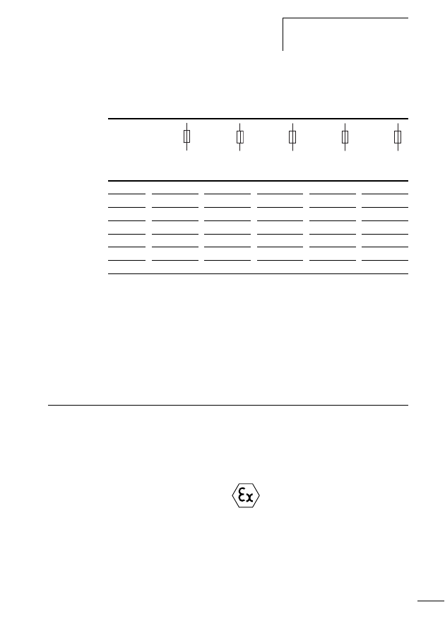
Tabelle 2:
Schaltvermögen PKZM4/XTPR…DC1 mit Zuord-
nungsart „1“
und „2“
1) Bemessungsdauerstrom
I
u
2) Bedingter Bemessungskurzschlussstrom
I
q
gemäß der Norm
IEC/EN 60 947-4-1
3) Erforderliche Vorsicherung, falls der Kurzschlussstrom den
bedingten Bemessungskurzschlussstrom der Geräte übersteigt
(I
cc
I
q
). Der bedingte Bemessungskurzschlussstrom ist
abhängig von der
verwendeten Vorsicherung.
4) N = nicht erforderlich
Zulassungen
Der Motorschutzschalter PKZM4/XTPR…DC1 ist nach der
Vorschrift IEC EN 60947 Niederspannungsschaltgeräte
gebaut und erfüllt die Forderungen nach der Richtlinie
94/9/EG (ATEX 100a) zum Schutz von Motoren im
Ex e-Bereich.
Das System ist nach UL und CSA für die USA und Kanada
approbiert.
230 V
400 V
440 V
500 V
690 V
I
u
1)
I
q
2)
I
q
2)
I
q
2)
I
q
2)
I
q
2)
A
kA
A
3)
kA
A
3)
kA
A
3)
kA
A
3)
kA
A
3)
16
150
N
150
N
45
100
15
100
8
100
25
150
N
150
N
45
100
15
100
8
100
32
50
100
50
100
45
100
15
100
5
100
40
50
100
50
100
45
100
15
100
5
100
50
50
100
50
100
45
100
15
100
5
100
58
50
160
50
160
45
160
15
160
5
160
63
50
160
50
160
45
160
15
160
5
160
c
U
s
0102
II(2)G
PTB 10 ATEX 3012

14
01/11 MN03402002Z-DE/EN

15
01/11 MN03402002Z-DE/EN
3
Installation
Hinweise zur Installation
h
Bei der mechanischen und elektrischen Installation ist die
Montageanweisung IL03407012Z (frühere Bezeichnung
AWA1210-1859) auf der Innenseite der Kartonverpa-
ckung zu beachten.
j
Gefahr!
Rücksetzungen dürfen manuell vor Ort oder durch
geschultes Personal in der Leitwarte vorgenommen
werden.
Installation
16
01/11 MN03402002Z-DE/EN
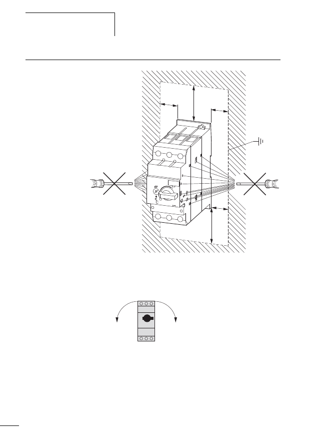
Geräte montieren
Abbildung 6: Montage PKZM4/XTPR…DC1
X
Montieren Sie den Motorschutzschalter nur wie in Abb. 7
dargestellt.
Abbildung 7: Zugelassene Einbaulage für Motorschutzschalter
PKZM4/XTPR…DC1
f 15
f 15
f
55
f 15
f
55
90°
90°
Geräte montieren
17
01/11 MN03402002Z-DE/EN
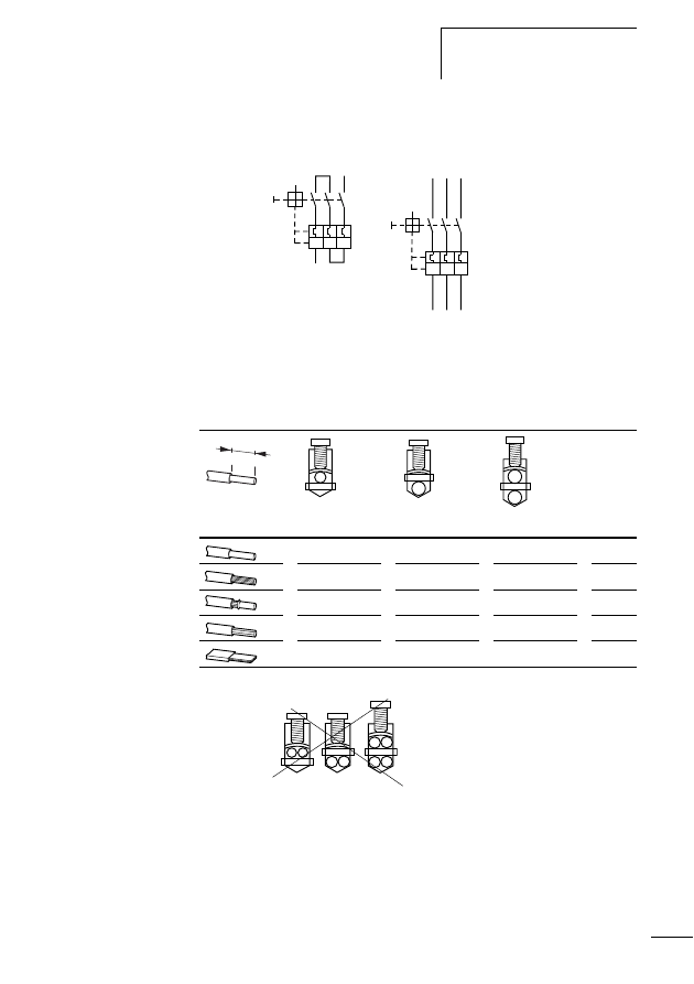
X
Verdrahten Sie die Motorleitungen.
Abbildung 8: Hauptstromverdrahtung
Folgende maximale Leitungsquerschnitte sind möglich.
Tabelle 3:
Maximale Leitungsquerschnitte der Motorzuleitungen
Abbildung 9: Unzulässige Leiteranordnung
>
I
>
I
>
I
>
I
>
I
>
I
[mm
2
]
[mm
2
]
[mm
2
]
[Nm]
0,75 - 50
0,75 - 50
0,75 - 35
3,3
0,75 - 35
0,75 - 35
0,75 - 25
3,3
0,75 - 35
0,75 - 35
0,75 - 25
3,3
16 - 50
16 - 50
16 - 35
3,3
6 x 9 x 0,8
6 x 9 x 0,8
6 x 9 x 0,8
3,3
14 mm
(0.55”)

18
01/11 MN03402002Z-DE/EN

19
01/11 MN03402002Z-DE/EN
4
Geräte betreiben
Einstellungen
Vor der Erstinbetriebnahme des Motorschutzschalters muss
der Motornennstrom mit Hilfe der Stromeinstellscheibe a
am PKZM4/XTPR…DC1 eingestellt werden (a Tabelle 1
auf Seite 7).
Test
Der Motorschutzschalter verfügt über eine Testeinrichtung
b (a Abb. 1 auf Seite 6). Wird diese Testeinrichtung bei
eingeschaltetem Motorschutzschalter mittels eines Schrau-
bendrehers betätigt, löst der PKZM4/XTPR…DC1 aus und
alle Hauptkontakte werden geöffnet. Damit wird die
Abgangsseite spannungsfrei geschaltet.
j
Gefahr!
Funktionsuntüchtige Geräte dürfen nicht geöffnet und
repariert werden. Sie müssen von Fachpersonal
ausgetauscht werden.

20
01/11 MN03402002Z-DE/EN

21
01/11 MN03402002Z-DE/EN
PKZM4/XTPR…DC1
motor-protective circuit-breakers
25
– Overload protection with motor-protective
– Current ranges of the PKZM4/XTPR…DC1
motor-protective circuit-breakers
Overload monitoring of Ex e motors
Setup of the overcurrent protection system
Short-circuit protection with motor-protective
circuit-breakers
Contents

Contents
22
01/11 MN03402002Z-DE/EN
Typenschild/Rating plate PKZM4/XTPR…01
Auslösekennlinien/Tripping characteristics
PKZM4/XTPR…DC1
– PKZM4-16/XTPR016DC1 42
– PKZM4-25/XTPR025DC1 43
– PKZM4-32/XTPR032DC1 44
– PKZM4-40/XTPR040DC1 45
– PKZM4-50/XTPR050DC1 46
– PKZM4-58/XTPR058DC1 47
– PKZM4-63/XTPR063DC1 48
EG-Konformitätserklärung/Declaration of
CE Conformity (Doc. No.: K 000411)
23
01/11 MN03402002Z-DE/EN
About this manual
This manual applies to the PKZM4/XTPR…DC1 motor-
protective circuit-breakers.
It describes the overload monitoring system for the protec-
tion of motors operating in potentially explosive atmo-
spheres (Ex e areas).
Target group
This manual is aimed at specialist personnel who are
responsible for the installation, commissioning and mainte-
nance of the motor protective circuit breaker.
Abbreviations and
symbols
Symbols used in this manual have the following meanings:
X
Indicates instructions to be followed
Ex e
Ignition protection type “Increased Safety”
PTB
Physikalisch Technische Bundesanstalt.
German Federal Testing Laboratory:
Accredited certification authority for devices
operated in Ex e areas.
NM
Lowest possible setting current
HM
Highest possible setting current
h
Draws your attention to interesting tips and supplemen-
tary information.
h
Caution!
warns of the risk of material damage.
j
Danger!
warns of the possibility of serious damage and slight injury
or death.

About this manual
24
01/11 MN03402002Z-DE/EN
For clarity of layout, we adhere to the following conventions
in this manual: at the top of left-hand pages you will find the
Chapter heading, at the top of right-hand pages the current
Section heading; exceptions are the first pages of Chapters
and empty pages at the end of Chapters.
List of revisions
As of publication date 01/11 this manual
AWB1210-1457D/GB has been renamed to
MN03402002Z-DE/EN.
The following significant amendments have been introduced
since the previous issue:
Publication
date
Page
Key word
New
Modi-
fica-
tion
De-
leted
01/11
General
Inclusion of Eaton models
j
General
EEx e (now: Ex e)
j
EC prototype test certification numbers
j
Typenschild/Rating plate
j
EG-Konformitätserklärung/
Declaration of CE Conformity
j
05/02
–
–
–
–
–

25
01/11 MN03402002Z-DE/EN
1
PKZM4/XTPR…DC1
motor-protective circuit-breakers
Foreword
In addition to the degree of protection specified in the
standards EN 60079-14 and VDE 0165 Part 1, further
provisions have been made to ensure safety from ignition for
motors operated in potentially explosive atmospheres.
EN 50019 prescribes additional measures to be taken for the
operation motors with “increased safety” type of protection
“e”. These measures improve the degree of safety and
prevent impermissible high temperature and development of
sparking and arcing, which is usually not found when motors
are operated under normal conditions.
The motor-protective devices for this that are themselves not
located in the Ex e area must be certified by an accredited
certification body.
Directive 94/9/EC (ATEX 100a) on the approximation of the
laws of the Member States concerning devices and protec-
tive systems intended for use in potentially explosive areas
has been in force since 06.30.2003.
The PKZM4/XTPR…DC1 motor protection system is
approved by the PTB according the 94/9/EC (ATEX 100a)
Directives.
h
Number of the EU Certificate of Compliance:
PTB 10 ATEX 3012.
((
PKZM4/XTPR…DC1 motor-
protective circuit-breakers
26
01/11 MN03402002Z-DE/EN
Device overview
Figure 1:
PKZM4/XTPR…DC1 motor-protective circuit-
breakers
a Dial for setting the rated motor current
b Testing element
Description of device
Overload protection with motor-protective
circuit-breakers
The PKZM4/XTPR…DC1 series are 3 pole electromechanical
motor-protective circuit-breakers with bimetallic release for
overload monitoring.
The PKZM4/XTPR…DC1 switch disconnects all phases from
the mains circuit when an overload occurs. The current flow
to the monitored motor is thus switched off directly.
(a see fig. 2)
Figure 2:
Circuit diagram of the PKZM4/XTPR…DC1 motor-
protective circuit-breakers
a
b
I > I > I >
L1 L2
L3
T1 T2 T3
-Q1

Description of device
27
01/11 MN03402002Z-DE/EN
Current ranges of the PKZM4/XTPR…DC1
motor-protective circuit-breakers
The rated motor current is set on the PKZM4/XTPR…DC1
units by means of a current dial a (a fig. 1, page 26).
Seven different types can be used to monitor motors
operating at a rated motor current of 10 to 63 A
(a table 1).
Table 1:
Current ranges of the
PKZM4/XTPR…DC1
Temperature compensation
Two parameters influence the deflection of the bimetallic
releases. There is for one the heat which is generated in
proportion to the current flow, and secondly, the influence of
the ambient air temperature. The influence of the ambient
air temperature is automatically compensated within a
temperature range from -5 to +55 °C by means of an addi-
tional current-free bimetallic release that continuously
corrects the tripping range.
Phase failure
The PKZM4/XTPR…DC1 motor-protective circuit-breakers
are phase failure sensitive. The deflecting action of all three
bimetallic releases is directed towards a tripping bridge that
Part no.
Current range I
e
[A]
PKZM4-16
XTPR016DC1
10 - 16
PKZM4-25
XTPR025DC1
16 - 25
PKZM4-32
XTPR032DC1
24 - 32
PKZM4-40
XTPR040DC1
32 - 40
PKZM4-50
XTPR050DC1
40 - 50
PKZM4-58
XTPR058DC1
50 - 58
PKZM4-63
XTPR063DC1
55 - 63
PKZM4/XTPR…DC1 motor-
protective circuit-breakers
28
01/11 MN03402002Z-DE/EN
switches over a quick-break switch when the limit value is
reached. At the same time, all three bimetallic releases shift
the differential bridge. If the path of action of one of the
bimetallic releases is reduced due to a phase loss, the
differential bridge is retarded and the distance is converted
into an additional tripping distance, which leads to an early
tripping.
Figure 3:
Function of the phase sensitivity by means of
tripping and differential bridge
a Trip bridge
b Differential bridge
c Distance
d Differential travel
Figure 4:
Wiring of the motor-protective circuit-breaker for
the protection of AC or DC motors (bimetallic
release switched in series)
(a section "Typenschild/Rating plate PKZM4/XTPR…01“
on page 41)
ab
c
d
e
f
g
ON
ON
OFF
three-phase
overload
Normal error-
free operation
Failure of one phase
(two-phase load)
h
When a PKZM4/XTPR…DC1 is to be used for monitoring
an AC or DC motor, the current must flow across all three
current paths in order to avoid early tripping.

Description of device
29
01/11 MN03402002Z-DE/EN
Reclosing
After tripping, the bimetallic releases must first cool down
before the motor-protective circuit-breaker can be reset.
Test function
Proper functioning of the circuit-breaker can be verified by
means of the testing feature b (a fig. 1, page 26).
The active PKZM4/XTPR…DC1 motor-protective circuit-
breaker is tripped by actuating the test release with the help
of a screwdriver. This allows the user to verify the proper
functioning of the motor-protective circuit-breaker in the
commissioning phase.
h
The PKZM4/XTPR…DC1 motor-protective circuit-breakers
can only be switched on locally.

30
01/11 MN03402002Z-DE/EN

31
01/11 MN03402002Z-DE/EN
2
Engineering
Overload monitoring of
Ex e motors
The Ex e protection of motors is achieved by means of
special design measures. The motors are assigned to temper-
ature classes on the basis of the highest permissible surface
temperatures. The temperature rise time t
E
and the ratio
between startup current and rated operational current I
A
/I
N
are calculated in addition and specified on the rating plate of
the motor.
The temperature rise time t
E
represents the time that expires
for the temperature of the motor winding to rise from its final
rated operational temperature up to the limit temperature,
at a startup current of I
A
.
However, Ex e motors are not intrinsically safe. Explosion
safety can only be achieved by taking additional measures
during installation and by selecting appropriate operating
conditions (PTB testing regulations), e.g. by adding a
correctly rated and set overload protection to the circuit.
Setup of the overcurrent
protection system
j
Danger!
The selected overload protection system must not only
ensure proper monitoring of the motor current, but also
that the seized motor is switched off within the tempera-
ture rise time t
E
.
This means:
The protective device must be rated in such a way so as to
ensure that the tripping time t
A
for the ratio I
A
/I
N
of the
Ex e motor is not higher than its temperature rise time t
E
according to its characteristics curve, in order to safely
switch off the motor within that period (a following
example).
Engineering
32
01/11 MN03402002Z-DE/EN
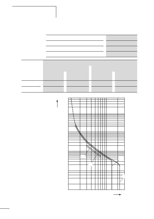
Example: I
A
/I
N
= 6, t
E
= 10 s
Figure 5:
Tripping characteristic for motor-protective circuit-
breaker
The motor is reliably protected.
Short-circuit protection
with motor-protective
circuit-breakers
The following table 2 shows the short-circuit breaking
capacity of the PKZM4/XTPR…DC1 motor-protective circuit-
breakers.
Fuse can be interconnected in the upstream circuit to
increase the switching capacity to 100 kA.
2
5
20
50
200
1
2
5
10
20
40
1
2
5
10
20
2h
1.5
2
3
4
6
8 10
15
20
30
x
I
r
t
min
s
ms
Approvals
33
01/11 MN03402002Z-DE/EN
Table 2:
Switching capacity of PKZM4/XTPR…DC1 with
type of coordination "1" and "2"
1) Rated uninterrupted current
I
u
2) Rated conditional short-circuit current
I
q
according to
IEC/EN 60 947-4-1 norm
3) Primary fusing is required if the short-circuit current exceeds the
conditional rated short-circuit current (I
cc
I
q
). The conditional
rated short-circuit current is determined by the
primary fuse.
4) N = Not required
Approvals
The PKZM4/XTPR…DC1 motor-protective circuit-breaker is
compliant with IEC/EN 60947 Standards for low-voltage
switchgear and fulfils the requirements of the
94/9/EC (ATEX 100a) directives for the protection of motors
operated in Ex e area.
The system is UL and CSA approved for use in USA and
Canada.
230 V
400 V
440 V
500 V
690 V
I
u
1)
I
q
2)
I
q
2)
I
q
2)
I
q
2)
I
q
2)
CSA
kA
A
3)
kA
A
3)
kA
A
3)
kA
A
3)
kA
A
3)
16
150
N
150
N
45
100
15
100
8
100
25
150
N
150
N
45
100
15
100
8
100
32
50
100
50
100
45
100
15
100
5
100
40
50
100
50
100
45
100
15
100
5
100
50
50
100
50
100
45
100
15
100
5
100
58
50
160
50
160
45
160
15
160
5
160
63
50
160
50
160
45
160
15
160
5
160
c
U
s
0102
II(2)G
PTB 10 ATEX 3012

34
01/11 MN03402002Z-DE/EN

35
01/11 MN03402002Z-DE/EN
3
Installation
Installation Instructions
h
The mechanical and electrical instructional leaflet
IL03407012Z (previous description AWA1210-1859) on
the inside of the cardboard package must be observed.
j
Danger!
A manual reset may be carried out by trained personnel
locally or in the control room.

Installation
36
01/11 MN03402002Z-DE/EN
Fitting the device
Figure 6:
Mounting the PKZM4/XTPR…DC1
X
Mount the motor protective circuit breaker only as shown
in fig. 7.
Figure 7:
Permitted mounting position of the
PKZM4/XTPR…DC1 motor-protective circuit-
breaker
f 15
f 15
f
55
f 15
f
55
90°
90°
Fitting the device
37
01/11 MN03402002Z-DE/EN
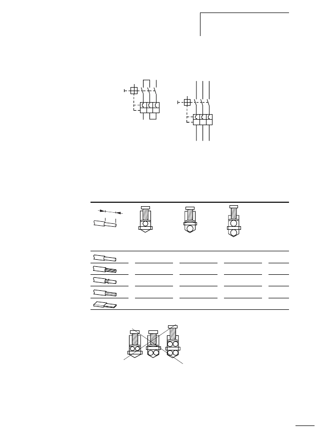
X
Wire the motor cables.
Figure 8:
Main circuit wiring
The following maximum cable cross sections are possible.
Table 3:
Maximum conductor cross-sections of the motor
cables
Figure 9:
Impermissible termination
>
I
>
I
>
I
>
I
>
I
>
I
[mm
2
]
[mm
2
]
[mm
2
]
[Nm]
0.75 - 50
0.75 - 50
0.75 - 35
3.3
0.75 - 35
0.75 - 35
0.75 - 25
3.3
0.75 - 35
0.75 - 35
0.75 - 25
3.3
16 - 50
16 - 50
16 - 35
3.3
6 x 9 x 0.8
6 x 9 x 0.8
6 x 9 x 0.8
3.3
14 mm
(0.55”)

38
01/11 MN03402002Z-DE/EN

39
01/11 MN03402002Z-DE/EN
4
Using the device
Settings
The rated motor current must be set on PKZM4/XTPR…DC1
by means of the current dial a (a table 1, page 27) prior
to initial commissioning of the motor-protective circuit-
breaker.
Test
The motor circuit-breaker is equipped with a testing feature
b (a fig. 1, page 26). The active PKZM4/XTPR…DC1
motor-protective circuit-breaker can be tripped by actuating
the test release with the help of a screwdriver. This opens all
power contacts and thus takes the output lines off voltage.
j
Danger!
Faulty devices must not be opened and repaired. They
must be replaced by specialist personnel.

40
01/11 MN03402002Z-DE/EN
41
01/11 MN03402002Z-DE/EN
Anhang/Appendix
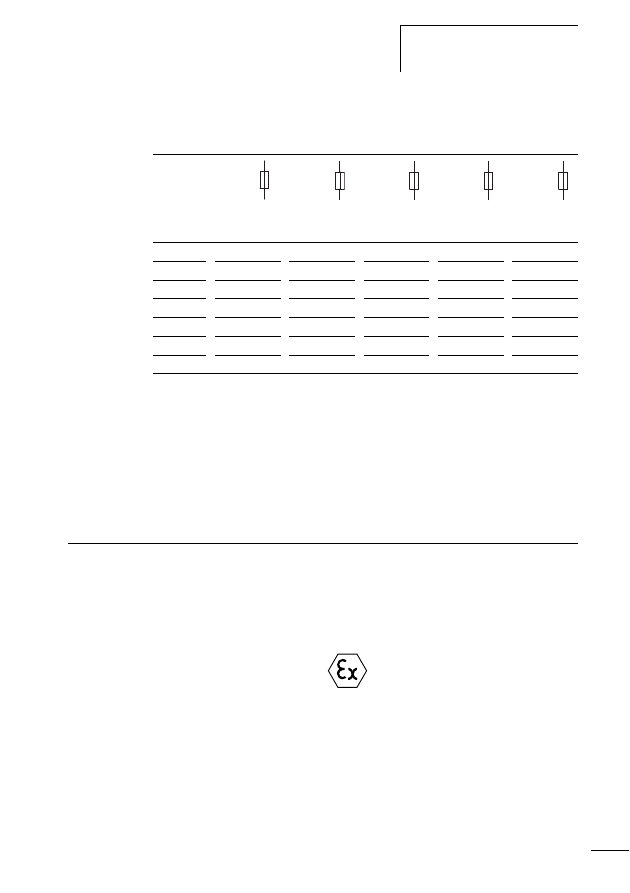
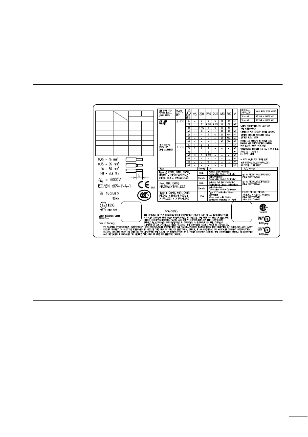
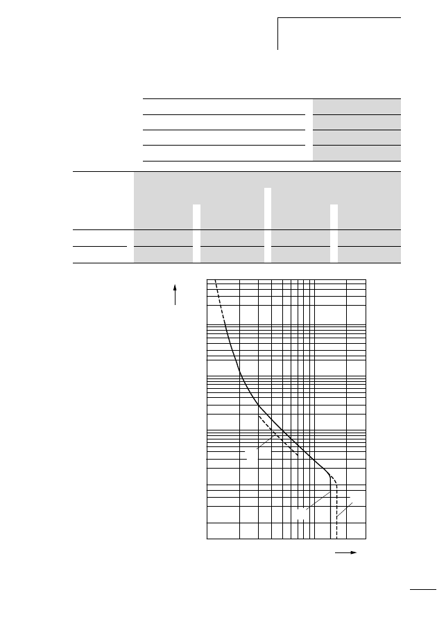
Typenschild/Rating plate
PKZM4/XTPR…DC1
Abbildung/Figure 10: Typenschild/Rating plate
PKZM4-…/XTPR…DC1
Auslösekennlinien/
Tripping characteristics
PKZM4/XTPR…DC1
50/60Hz
Type
PKZM4-16
16
50
8
PKZM4-25
25
50
8
PKZM4-32
32
50
5
PKZM4-40
40
50
5
PKZM4-50
50
50
5
PKZM4-58
58
50
5
PKZM4-63
XTPR016DC1
XTPR025DC1
XTPR032DC1
XTPR040DC1
XTPR050DC1
XTPR058DC1
XTPR063DC1
63
50
5
U
e
(Vh) 230/400 690
I
e
(A)
I
q
= I
cu
(kA)
Anhang/Appendix
42
01/11 MN03402002Z-DE/EN
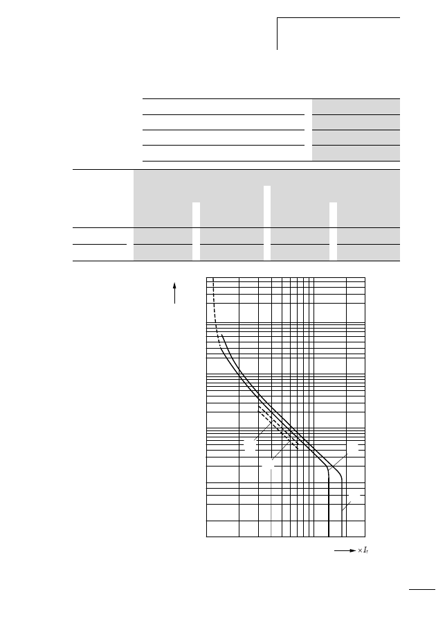
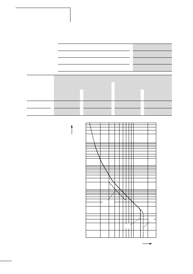
PKZM4-16/XTPR016DC1
Abbildung/Figure 11: PKZM4-16/XTPR016DC1
Bereich/Range
10 - 16 A (NM - HM)
Umgebungstemperatur/Ambient temperature
20 °C
Auslöseklasse/Tripping class
10 A
Toleranzbereich/Tolerance range
g
20 %
Einstellung/
Setting
Auslösezeit/Tripping time t [s]
NM
HM
3-phase b
2-phase c
3-phase a
2-phase d
3 x I
r
37.1
21.8
31.5
18.5
7.2 x I
r
8.4
5.8
7.4
5
1
0.1
0.2
0.4
0.6
1
10
2
4
6
6000
1000
100
40
20
2
3
4
5 6 7 8 9 10
20
30
t
x
I
r
a
b
c
d
[s]
Auslösekennlinien/Tripping
characteristics PKZM4/
XTPR…DC1
43
01/11 MN03402002Z-DE/EN
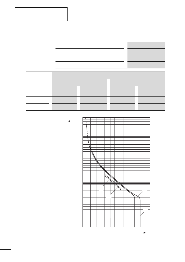
PKZM4-25/XTPR025DC1
Abbildung/Figure 12: PKZM4-25/XTPR025DC1
Bereich/Range
16 - 25 A (NM - HM)
Umgebungstemperatur/Ambient temperature
20 °C
Auslöseklasse/Tripping class
10 A
Toleranzbereich/Tolerance range
g
20 %
Einstellung/
Setting
Auslösezeit/Tripping time t [s]
NM
HM
3-phase b
2-phase c
3-phase a
2-phase d
3 x I
r
46.0
26.3
35.8
20.8
7.2 x I
r
7.9
5.0
6.5
3.9
a
b
c
d
1
0.1
0.2
0.4
0.6
1
10
2
4
6
6000
1000
100
40
20
2
3
4
5 6 7 8 9 10
20
30
t
[s]
Anhang/Appendix
44
01/11 MN03402002Z-DE/EN
PKZM4-32/XTPR032DC1
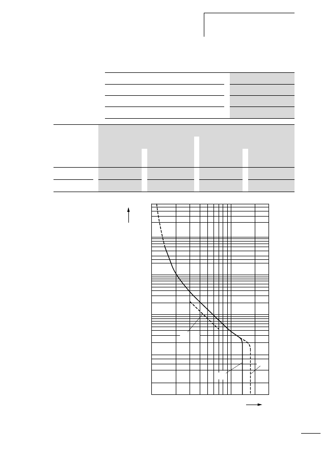
Abbildung/Figure 13: PKZM4-32/XTPR032DC1
Bereich/Range
24 - 32 A (NM - HM)
Umgebungstemperatur/Ambient temperature
20 °C
Auslöseklasse/Tripping class
10 A
Toleranzbereich/Tolerance range
g
20 %
Einstellung/
Setting
Auslösezeit/Tripping time t [s]
NM
HM
3-phase b
2-phase c
3-phase a
2-phase d
3 x I
r
32.6
19.6
30.3
18
7.2 x I
r
6.9
4.3
6.2
3.9
a
b
c
d
1
0.1
0.2
0.4
0.6
1
10
2
4
6
6000
1000
40
20
2
3
4 5 6 7 8 910
20
30
t
x
I
r
[s]
Auslösekennlinien/Tripping
characteristics PKZM4/
XTPR…DC1
45
01/11 MN03402002Z-DE/EN
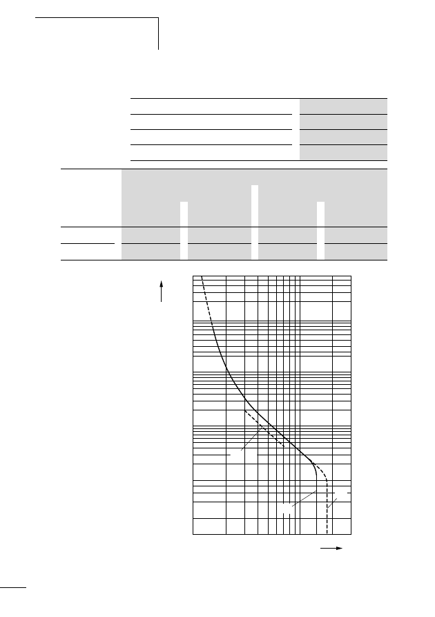
PKZM4-40/XTPR040DC1
Abbildung/Figure 14: PKZM4-40/XTPR040DC1
Bereich/Range
32 - 40 A (NM - HM)
Umgebungstemperatur/Ambient temperature
20 °C
Auslöseklasse/Tripping class
10 A
Toleranzbereich/Tolerance range
g
20 %
Einstellung/
Setting
Auslösezeit/Tripping time t [s]
NM
HM
3-phase b
2-phase c
3-phase a
2-phase d
3 x I
r
38.9
22.6
38.9
22.6
7.2 x I
r
6.8
4.2
6.8
4.2
b
c d
a
1
0.1
0.2
0.4
0.6
1
10
2
4
6
6000
1000
100
40
20
2
3
4
5 6 7 8 9 10
20
30
t
x
I
r
[s]
Anhang/Appendix
46
01/11 MN03402002Z-DE/EN
PKZM4-50/XTPR050DC1
Abbildung/Figure 15: PKZM4-50/XTPR050DC1
Bereich/Range
40 - 50 A (NM - HM)
Umgebungstemperatur/Ambient temperature
20 °C
Auslöseklasse/Tripping class
10 A
Toleranzbereich/Tolerance range
g
20 %
Einstellung/
Setting
Auslösezeit/Tripping time t [s]
NM
HM
3-phase b
2-phase c
3-phase a
2-phase d
3 x I
r
20.1
20.1
32
32
7.2 x I
r
4.1
4.1
5.9
5.9
a
b
c d
1
0.1
0.2
0.4
0.6
1
10
2
4
6
6000
1000
100
40
20
2
3
4
5 6 7 8 9 10
20
30
t
x
I
r
[s]
Auslösekennlinien/Tripping
characteristics PKZM4/
XTPR…DC1
47
01/11 MN03402002Z-DE/EN
PKZM4-58/XTPR058DC1
Abbildung/Figure 16: PKZM4-58/XTPR058DC1
Bereich/Range
50 - 58 A (NM - HM)
Umgebungstemperatur/Ambient temperature
20 °C
Auslöseklasse/Tripping class
10 A
Toleranzbereich/Tolerance range
g
20 %
Einstellung/
Setting
Auslösezeit/Tripping time t [s]
NM
HM
3-phase b
2-phase c
3-phase a
2-phase d
3 x I
r
20.7
20.7
34
34
7.2 x I
r
3.6
3.6
5.5
5.5
a
b
c d
1
0.1
0.2
0.4
0.6
1
10
2
4
6
1000
6000
100
40
20
2
3
4
5 6 7 8 9 10
20
30
t
x
I
r
[s]
Anhang/Appendix
48
01/11 MN03402002Z-DE/EN
PKZM4-63/XTPR063DC1
Abbildung/Figure 17: PKZM4-63/XTPR063DC1
Bereich/Range
55 - 63 A (NM - HM)
Umgebungstemperatur/Ambient temperature
20 °C
Auslöseklasse/Tripping class
10 A
Toleranzbereich/Tolerance range
g
20 %
Einstellung/
Setting
Auslösezeit/Tripping time t [s]
NM
HM
3-phase b
2-phase c
3-phase a
2-phase d
3 x I
r
20.5
20.5
41
41
7.2 x I
r
3.2
3.2
5.4
5.4
a
b
c d
1
0.1
0.2
0.4
0.6
1
10
2
4
6
6000
1000
100
40
20
2
3
4
5 6 7 8 9 10
20
30
t
x
I
r
[s]
EG-Konformitätserklärung/
Declaration of CE Conformity
(Doc. No.: K 000411)
49
01/11 MN03402002Z-DE/EN
EG-Konformitätserklärung/Declaration of CE Conformity (Doc. No.: K 000411)
Doc. No.: K 000411
EG-Konformitätserklärung
Dec
Declaration of CE Conformity
Wir / We, Eaton Industries GmbH,
Hein-Moeller-Str. 7-11, 53115 Bonn (Germany),
erklären hiermit, dass das Produkt (die Produktfamilie)
declare that product (family)
Motorschutzschalter
Motor-protective circuit-breaker
vorausgesetzt, dass es unter Berücksichtigung der relevanten Herstellerangaben,
Einbauanweisungen und “anerkannten Regeln der Technik” installiert, gewartet
und in den dafür vorgesehenen Anwendungen verwendet wird,
provided that it is installed, maintained and used in the application intended for, with respect to the relevant
manufacturers instructions, installation standards and “good engineering practices”,
den einschlägigen Bestimmungen der Richtlinie(n) des Rates entspricht:
complies with the provisions of Council directive(s):
2004/108/EC
EMV-Richtlinie / EMC Directive
2006/95/EC
Niederspannungsrichtlinie / Low Voltage Directive
94/9/EC
ATEX-Richtlinie / ATEX Directive (PTB 10 ATEX 3012)
und mit den folgenden europäischen Normen übereinstimmt:
based on compliance with European standard(s):
EN 60947-4-1:2001 + A1:2002 + A2:2005
Niederspannungsschaltgeräte, Teil 4-1: Schütze und Motorstarter - Elektromechanische Schütze und Motorstarter
Low-voltage switchgear and controlgear, Part 4-1: Contactors and motor-starters - Electromechanical contactors and
motorstarters
EN 60947-5-1:2004
Niederspannungsschaltgeräte, Teil 5-1: Steuergeräte und Schaltelemente - Elektromagnetische Steuergeräte
Low-voltage switchgear and controlgear, Part 5-1: Control circuit devices and switching elements - Electromechanical
control circuit devices
Kennzeichnung:
II (2) G
Marking
10.01.2011
i.V. Ulrich Wölfel
ICD - Quality Management
Anhang/Appendix
50
01/11 MN03402002Z-DE/EN
Doc. No.: K 000411
Typen des Sortiments
Types within the range
Die Konformitätserklärung gilt für folgende Typen der Produktfamilie:
The declaration of conformity applies to the following types within the product family:
PKZM4-16...63
+ Zubehörteile / Accessories
AK-PKZ0
NHI..-PKZ0 (-C)
NHI-E(B)-...-PKZ0 (-C)
U(A)-PKZ0
AGM..PKZ0
VHI..-PKZ0
HB-PKZ4
(H)-B3-PKZ4
BK50/3-PKZ4-E
PKZM4-XM65DE (*)
PKZM4-XDM65 (*)
PKZM4-XC55/2 (*)
PKZM0-X(R)H (**)
CI-K4-PKZ4-G(R) (+)
CI-K4-PKZ4(-NA)-G(R) (**)
+ SVB-PKZ4-CI
+ KT-M(20)(25)(32)(G)
+ V-M(20)(25)(32)(G)
+ L-PKZ0(-GN)(-RT)(...V)
Datum des CE-Zeichens: 2000 (+) 2002, (*) 2005, (**) 2007
Affixing date of CE mark:
10.01.2011
i.V. Ulrich Wölfel
ICD - Quality Management

51
01/11 MN03402002Z-DE/EN
Eaton Corporation
Eaton ist ein führendes Energie-
Management-Unternehmen. Weltweit
ist Eaton mit Produkten, Systemen und
Dienstleistungen in den Bereichen Electrical,
Hydraulics, Aerospace, Truck und
Automotive tätig.
Eatons Electrical Sector
Eatons Electrical Sector ist weltweit führend
bei Produkten, Systemen und Dienstleistungen
zu Energieverteilung, sicherer Stromversorgung
und Automatisierung in der Industrie, in Wohn- und
Zweckbauten, öffentlichen Einrichtungen, bei Energie-
versorgern, im Handel und bei OEMs.
Zu Eatons Electrical Sector gehören
die Marken Cutler-Hammer®, Moeller®,
Micro Innovation, Powerware®, Holec®,
MEM® und Santak®.
www.eaton.com
01/11 MN03402002Z-DE/EN
ersetzt/replaces 05/02 AWB1210-1457D/GB
Handbuch/Manual
PKZM4/
XT
PR…DC1
Motorschutzschalter PKZM4/XTPR…DC1
Überlastüberwachung von Ex e-Motoren
PKZM4/XTPR…DC1 motor-protective circuit-breaker
Overload monitoring of Ex e motors
Eaton Corporation
Eaton is a leading power
management company. Eaton
operates worldwide with products,
systems and services in the
electrical, hydraulic, aerospace,
truck and automotive sectors.
Eatons Electrical Sector
Eatons Electrical Sector is the
worldwide leader in products,
systems and services for energy
distribution, safe electricity supply
and automation in industrial,
residential and purpose-built
buildings, public facilities, energy
providers, commerce and OEMs.
Eaton Electrical Sector includes the
brands Cutler-Hammer®, Moeller®,
Micro Innovation, Powerware®,
Holec®, MEM® and Santak®
www.eaton.com
Eaton addresses worldwide:
www.moeller.net/address
E-Mail: info-bonn@eaton.com
Internet: www.eaton.com/moellerproducts
www.eaton.com
Herausgeber/Issued by: Eaton Industries GmbH
Hein-Moeller-Str. 7–11
D-53115 Bonn
© 2002 by Eaton Industries GmbH
Änderungen vorbehalten/Subject to alteration
MN03402002Z-DE/EN Doku/Doku/Eb 01/11
Printed in Germany (02/11)
Artikel-Nr./Article No.: 151985
4 *patpka#v,mccx*
Rückenbreite 2 mm
(1 Blatt = 0,080 mm für Eberwein Digitaldruck bei 80 g/m
2
)
Document Outline
- Titel/Title
- Impressum/Imprint
- Sicherheitshinweise/Safety Instructions
- Überblick/Overview
- Inhalt
- Zu diesem Handbuch
- 1 Motorschutzschalter PKZM4/XTPR…DC1
- 2 Projektierung
- 3 Installation
- 4 Geräte betreiben
- Contents
- About this manual
- 1 PKZM4/XTPR…DC1 motor-protective circuit-breakers
- 2 Engineering
- 3 Installation
- 4 Using the device
- Anhang/Appendix
- Rückseite/Rear cover
Wyszukiwarka
Podobne podstrony:
PKZM4XTPR…DC1 motor protective circuit breaker
Motor protective circuit breaker PKZM0XTPR…BC1
Motor protective circuit breaker PKZM0XTPR…BC1
04 ISF2 CIRCUIT BREAKERS
Circuit Breakers
Motor protective relays ZB65XTOB…DC1 and
04 SF CIRCUIT BREAKERS
INNE ZE motor protective relay h1425g
Motor protective relays ZB65XTOB…DC1 and
fuses and circuit breakers
Circuito del ventilador de refrigeración Toyota Corolla 1997
INNE Circuit Breaker Test Device h1585dgb
Circuit Breakers
371281 in 01 ml TELE ATL NAVIFLASH EU07CF de en fr nl it
Baumer NE210 DE EN
Lenze Moduł 8201BB obsługi falownika serii 8200 DE EN FR
więcej podobnych podstron