
Adam Paweł Zaborski
Project “The development of the didactic potential of Cracow University of Technology in the range of
modern construction” is co-financed by the European Union within the confines of the European Social Fund
and realized under surveillance of Ministry of Science and Higher Education.
15. Strain state
Introduction
Definitions
deformation – occurs when the distance between the trajectories of two points changes and/or the angle
between the two lines on the body changes
we distinguish two configurations: original (undeformed) and final (deformed)
displacement – difference of a point position in original and final configuration
material (Lagrangian) description – original material configuration is used as a reference (usually it is the
case in solid mechanics, where we observe the displacement of a point at the bridge mid-span due to
loading)
spatial (Eulerian) description – spatial coordinate set is used as a reference (usually it is the case in
hydromechanics, where we consider the pressure or velocity at some point in a pipeline, we are not
interested in the fact which particle passes through the point)
Lagrangian strain – a strain computed by using original geometry as a reference
Eulerian strain – a strain computed by using deformed geometry as a reference
normal strain – a ratio of deformation to original length
shear strain – a half-change of angle from a right angle
Note:
strain is dimensionless
strain value is much smaller than unity (less than 0.001 for instance), we call it infinitesimal
for infinitesimal strains the difference between Lagrangian and Eulerian strains becomes unimportant
strain matrix - a matrix with normal strains on the diagonal and shear strains elsewhere.
The strain matrix is a tensor and transforms according t transformation formula:
– in index notation:
kl
jl
ik
ij
a
a
ε
=
ε
– in matrix notation:
T
A
A
⋅
Ε
⋅
=
Ε'
where:
–
ij
ε
is a strain matrix with normal strain on the diagonal and shear strain elsewhere:
4
4
4
4
3
4
4
4
4
2
1
4
4
4
3
4
4
4
2
1
4
4
4
3
4
4
4
2
1
notation)
g
engineerin
("old"
z
zy
zx
yz
y
yz
xz
xy
x
notation)
ng
(engineeri
z
zy
zx
yz
y
yz
xz
xy
x
notation)
c
(scientifi
ε
γ
γ
γ
ε
γ
γ
γ
ε
=
ε
ε
ε
ε
ε
ε
ε
ε
ε
=
ε
ε
ε
ε
ε
ε
ε
ε
ε
=
ε
2
1
2
1
2
1
2
1
2
1
2
1
33
32
31
23
22
21
13
12
11
ij
Single index specifies the direction of the fiber, a pair of indexes specifies the directions of the fibers that
determine the considered angle.
A matrix can be the strain matrix if it fulfills the compatibility equations:
0
,
,
,
,
=
ε
−
ε
−
ε
+
ε
ik
jl
jl
ik
ij
kl
kl
ij
and the kinematic boundary conditions.
The relationships between the displacement vector and infinitesimal strains are expressed in partial
derivatives (Cauchy’s equations):
∂
∂
+
∂
∂
=
ε
∂
∂
+
∂
∂
=
ε
∂
∂
+
∂
∂
=
ε
∂
∂
=
ε
∂
∂
=
ε
∂
∂
=
ε
y
w
z
v
x
w
z
u
x
v
y
u
z
w
y
v
x
u
yz
xz
xy
z
y
x
2
1
,
2
1
,
2
1
,
,
,
.
The strain state analysis is identical to the stress state analysis.
Adam Paweł Zaborski
Project “The development of the didactic potential of Cracow University of Technology in the range of
modern construction” is co-financed by the European Union within the confines of the European Social Fund
and realized under surveillance of Ministry of Science and Higher Education.
Strain measurement in plane strain state
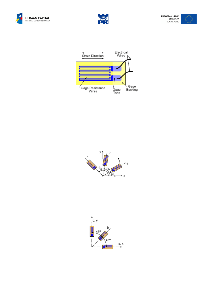
The strains can be measured by the strain gauges. The normal strain is measured by a gauge constructed
from a single wire that is wound back and forth, Fig. 15.1, attached to the surface of the tested object.
Fig. 15.1 Strain gauge
The electrical resistance changes in the direction opposite to the strain change. Most strain gauge
measurement devices automatically collaborate the resistance change to the strain, so the device output is
the actual strain.
Since a single gauge can only measure the strain in a single direction only, two gauges are needed to
determine strain in the x and y directions. However, there is no gauge which is capable of measuring shear
strain.
Because any transformed normal strain is a function of the coordinate strains,
xy
y
x
ε
ε
ε
,
,
, three rotated
different gauges give three equations with three unknowns
xy
y
x
ε
ε
ε
,
,
. Any three gauges used together at
one location on a stressed object are called a strain rosette, Fig. 15.2.
Fig. 15.2 Strain gauge rosette
Example – strain rosette 45
°°°°
The strains measured by the strain rosette 45
° are:
0005
.
0
=
ε
a
,
0002
.
0
=
ε
b
,
0003
.
0
−
=
ε
c
. Determine the
strain components and compute principal strains and their directions.
Solution
In this case the gauges are separated by an angle of 45
°, Fig. 15.3:
Fig. 15.3 Rosette at 45
°
The direction of a and x are the same, so
0005
.
0
=
ε
=
ε
a
x
. Similarly, the direction of c coincides with the
direction of y, so
0003
.
0
−
=
ε
=
ε
c
y
. For the strain in the direction of b we have:
Adam Paweł Zaborski
Project “The development of the didactic potential of Cracow University of Technology in the range of
modern construction” is co-financed by the European Union within the confines of the European Social Fund
and realized under surveillance of Ministry of Science and Higher Education.
xy
xy
xy
yx
xy
y
x
b
x
b
by
y
b
x
b
y
b
x
b
ε
+
−
−
=
=
⋅
ε
⋅
+
⋅
−
⋅
=
⋅
⋅
ε
⋅
+
⋅
−
⋅
=
=
ε
+
ε
+
ε
+
ε
=
ε
00015
.
0
00025
.
0
5
.
0
2
5
.
0
0003
.
0
5
.
0
0005
.
0
45
cos
45
cos
2
)
45
(cos
0003
.
0
)
45
(cos
0005
.
0
)
,
cos(
)
cos(
)
,
cos(
)
,
cos(
)
,
(
cos
)
,
(
cos
2
2
2
2
.
At the same time
0002
.
0
=
ε
b
, so:
0001
.
0
0002
.
0
0001
.
0
=
ε
→
=
ε
+
xy
xy
and
−
=
0003
.
0
0001
.
0
0001
.
0
0005
.
0
e
T
.
The principal strains are:
000512
.
0
000412
.
0
0001
.
0
0001
.
0
2
0003
.
0
0005
.
0
2
0003
.
0
0005
.
0
2
2
2
2
2
2
1
=
+
=
+
+
+
−
=
ε
+
ε
−
ε
+
ε
+
ε
=
ε
xy
y
x
y
x
000312
.
0
000412
.
0
0001
.
0
0001
.
0
2
0003
.
0
0005
.
0
2
0003
.
0
0005
.
0
2
2
2
2
2
2
1
=
−
=
+
+
−
−
=
ε
+
ε
−
ε
−
ε
+
ε
=
ε
xy
y
x
y
x
The principal directions are:
)
8
.
6
(
12
.
0
12
.
0
0001
.
0
0005
.
0
000512
.
0
tan
1
°
=
=
α
→
=
−
=
ε
ε
−
ε
=
α
xy
x
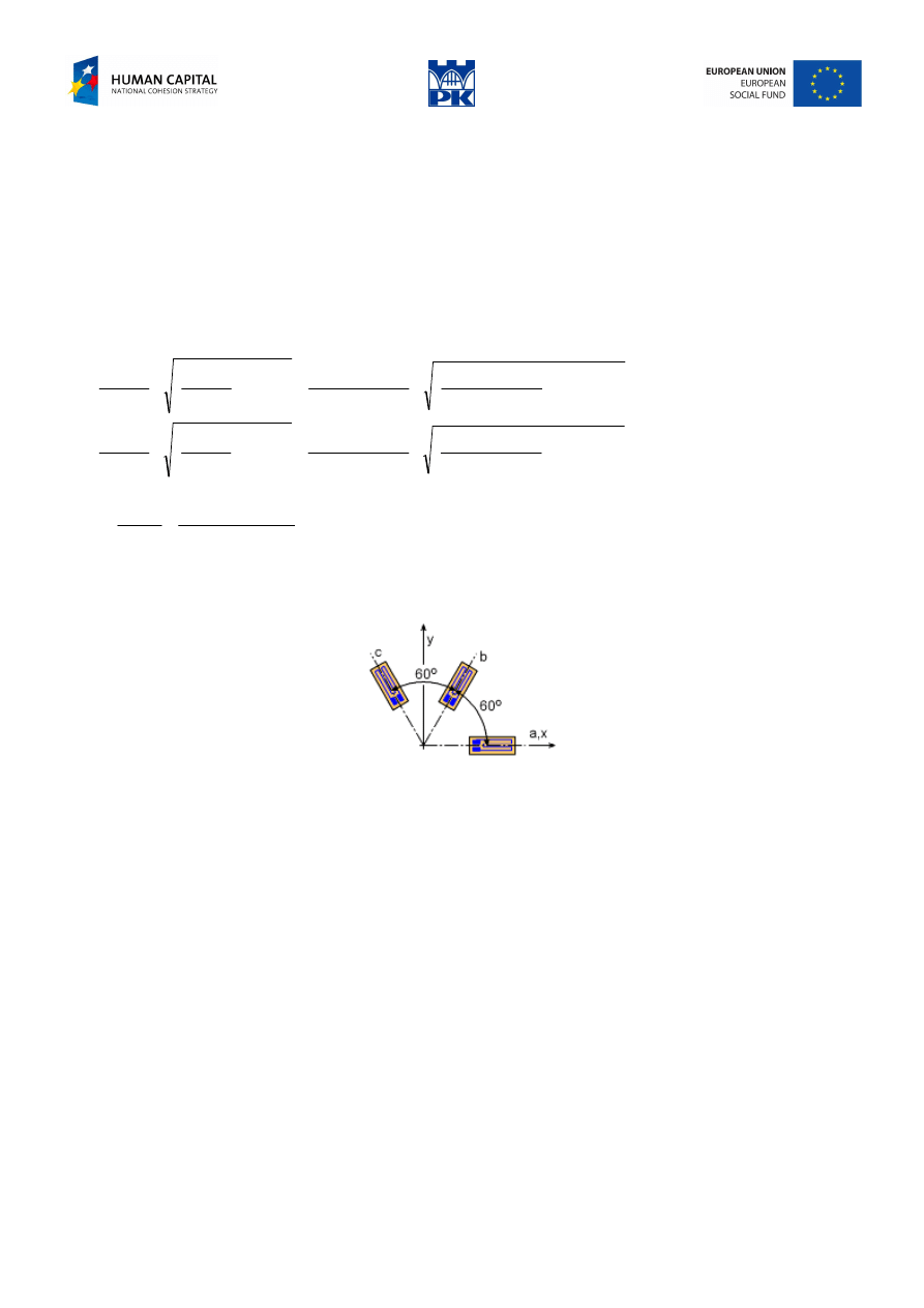
Workshop theme
The strains measured by the strain rosette 60
°, Fig. 15.4, are:
Fig. 15.4 Strain rosette 60
°
)
0007
.
0
0001
.
0
(
÷
−
=
ε
K
K
K
a
,
)
0007
.
0
0004
.
0
(
÷
−
=
ε
K
K
K
b
,
)
0002
.
0
0002
.
0
(
÷
−
=
ε
K
K
K
c
.
Determine the strain components and compute principal strains and their directions.
Addendum
Glossary
deformation – deformacja
original (undeformed) configuration – konfiguracja początkowa, pierwotna, nieobciążona
final (deformed) configuration – konfiguracja końcowa, aktualna, obciążona
displacement – przemieszczenie
material (Lagrangian) description – opis materialny, lagranżowski
spatial (Eulerian) description – opis przestrzenny, eulerowski
Lagrangian strain – odkształcenie we współrzędnych materialnych
Eulerian strain – odkształcenie we współrzędnych przestrzennych
normal strain – odkształcenie normalne, liniowe
shear strain – odkształcenie kątowe

Adam Paweł Zaborski
Project “The development of the didactic potential of Cracow University of Technology in the range of
modern construction” is co-financed by the European Union within the confines of the European Social Fund
and realized under surveillance of Ministry of Science and Higher Education.
compatibility equations – równania nierozdzielności
kinematic boundary conditions – kinematyczne warunki brzegowe
gauge, (AmE gage) – czujnik
strain rosette – rozeta tensometryczna
Wyszukiwarka
Podobne podstrony:
C07 design 11 AZ
C07 design 12 AZ
C07 design 08 AZ
C07 design 02 AZ
C07 design 03 AZ
C07 design 09 az
C07 design 05 AZ
C07 design 10 AZ
C07 design 06 AZ
C07 design 01 AZ
C07 design 03 AZ
C07 design 02 AZ
C07 design 09 AZ
C07 design 10 AZ
C07 design 01 AZ
C07 design 06 AZ
C07 design 08 AZ
C07 design 14 AZ
C07 design 13 AZ
więcej podobnych podstron