
Software complexity
Software complexity
estimation
estimation
by Adam Bondarowicz
by Adam Bondarowicz

cocomo
cocomo
"COnstructive COst MOdel"
"COnstructive COst MOdel"
COCOMO
COCOMO
is a model designed by
is a model designed by
to
to
give an estimate of the number of man-months it will
give an estimate of the number of man-months it will
take to
a
product.

cocomo
cocomo
COCOMO
COCOMO
consists of a hierarchy of three increasingly detailed
consists of a hierarchy of three increasingly detailed
and accurate forms.
and accurate forms.
Basic COCOMO
Basic COCOMO
- is a static, single-valued model that computes
- is a static, single-valued model that computes
software development effort (and cost) as a function of program
software development effort (and cost) as a function of program
size expressed in estimated lines of code.
size expressed in estimated lines of code.
Intermediate COCOMO
Intermediate COCOMO
- computes software development
- computes software development
effort as function of program size and a set of "cost drivers" that
effort as function of program size and a set of "cost drivers" that
include subjective assessment of product, hardware, personnel
include subjective assessment of product, hardware, personnel
and project attributes.
and project attributes.
Detailed COCOMO
Detailed COCOMO
- incorporates all characteristics of the
- incorporates all characteristics of the
intermediate version with an assessment of the cost driver's
intermediate version with an assessment of the cost driver's
impact on each step (analysis, design, etc.) of the software
impact on each step (analysis, design, etc.) of the software
engineering process.
engineering process.

basic
basic
cocomo
cocomo
Used for:
Used for:
Organic projects
Organic projects
- relatively small, simple software
- relatively small, simple software
projects in which small teams with good application
projects in which small teams with good application
experience work to a set of less than rigid
experience work to a set of less than rigid
requirements.
requirements.
Semi-detached projects
Semi-detached projects
- intermediate (in size and
- intermediate (in size and
complexity) software projects in which teams with
complexity) software projects in which teams with
mixed experience levels must meet a mix of rigid and
mixed experience levels must meet a mix of rigid and
less than rigid requirements.
less than rigid requirements.
Embedded projects
Embedded projects
- software projects that must be
- software projects that must be
developed within a set of tight hardware, software,
developed within a set of tight hardware, software,
and operational constraints.
and operational constraints.

basic COCOMO
basic COCOMO
equations
equations
E=a
E=a
b
b
(KLOC)
(KLOC)
b
b
b
b
D=c
D=c
b
b
(E)
(E)
d
d
b
b
P=E/D
P=E/D
E is the effort applied in person-months
E is the effort applied in person-months
D is the development time in chronological months
D is the development time in chronological months
KLOC is the estimated number of delivered lines of code for the project (expressed in thousands)
KLOC is the estimated number of delivered lines of code for the project (expressed in thousands)

cocomo coefficients
cocomo coefficients
a
a
b
b
,
,
b
b
b
b
,
,
c
c
b
b
and
and
d
d
b
b
Software project a
Software project a
b
b
b
b
b
b
c
c
b
b
d
d
b
b
Organic 2.4 1.05 2.5 0.38
Organic 2.4 1.05 2.5 0.38
Semi-detached 3.0 1.12 2.5 0.35
Semi-detached 3.0 1.12 2.5 0.35
Embedded 3.6 1.20 2.5 0.32
Embedded 3.6 1.20 2.5 0.32

Basic cocomo summary
Basic cocomo summary
Basic COCOMO
Basic COCOMO
is good for
is good for
quick, early, rough
quick, early, rough
order of
order of
magnitude estimates of software costs, but its
magnitude estimates of software costs, but its
accuracy is limited
accuracy is limited
because of its
because of its
lack of factors
lack of factors
to
to
account for differences in hardware constraints,
account for differences in hardware constraints,
personnel quality and experience, use of modern tools
personnel quality and experience, use of modern tools
and techniques, and other project attributes known to
and techniques, and other project attributes known to
have a significant influence on software costs.
have a significant influence on software costs.

Extended cocomo
Extended cocomo
The basic model is extended to
The basic model is extended to
consider a set of "cost driver
consider a set of "cost driver
attributes" that can be grouped
attributes" that can be grouped
into four major categories:
into four major categories:

1.
1.
Product attributes
Product attributes
a. required software reliability
a. required software reliability
b. size of application data base
b. size of application data base
c. complexity of the product
c. complexity of the product

2.
2.
Hardware attributes
Hardware attributes
a. run-time performance constraints
a. run-time performance constraints
b. memory constraints
b. memory constraints
c. volatility of the virtual machine
c. volatility of the virtual machine
environment
environment
d. required turnaround time
d. required turnaround time

3.
3.
Personnel attributes
Personnel attributes
a. analyst capability
a. analyst capability
b. software engineer capability
b. software engineer capability
c.applications experience
c.applications experience
d. virtual machine experience
d. virtual machine experience
e. programming language experience
e. programming language experience

4.
4.
Project attributes
Project attributes
a. use of software tools
a. use of software tools
b. application of software engineering
b. application of software engineering
methods
methods
c. required development schedule
c. required development schedule

Each of the 15 attributes is rated on a 6 point scale
Each of the 15 attributes is rated on a 6 point scale
that ranges from "very low" to "extra high" (in
that ranges from "very low" to "extra high" (in
importance or value)
importance or value)
Based on the rating, an effort multiplier is determined
Based on the rating, an effort multiplier is determined
from tables published by Boehm [BOE81], and the
from tables published by Boehm [BOE81], and the
product of all effort multipliers results is an
product of all effort multipliers results is an
effort
effort
adjustment factor
adjustment factor
(EAF)
(EAF)
. Typical values for EAF range
. Typical values for EAF range
from 0.9 to 1.4.
from 0.9 to 1.4.

intermediate COCOMO equation
intermediate COCOMO equation
E = a
E = a
i
i
KLOC
KLOC
b
b
i
i
x
x
EAF
EAF
E
E
is the effort applied in person-months
is the effort applied in person-months
KLOC
KLOC
is the estimated number of delivered lines of code for
is the estimated number of delivered lines of code for
the project
the project

Intermediate cocomo
Intermediate cocomo
coefficients
coefficients
Software
project
a
i
b
i
organic
3.2
1.05
Semi-detached
3.0
1.12
embedded
2.8
1.20

Example
Example
Using the LOC estimate and the coefficients noted in table, we use the
Using the LOC estimate and the coefficients noted in table, we use the
basic model to get:
basic model to get:
E = 2.4 (KLOC)
E = 2.4 (KLOC)
1.05
1.05
= 2.4 (33.2)
= 2.4 (33.2)
1.05
1.05
= 95 person-months
= 95 person-months

Cocomo II
Cocomo II
C
C
OCOMO II is a model that allows one
OCOMO II is a model that allows one
to estimate the cost, effort, and
to estimate the cost, effort, and
schedule when planning a new
schedule when planning a new
software development activity. It
software development activity. It
consists of three submodels, each one
consists of three submodels, each one
offering increased fidelity the further
offering increased fidelity the further
along one is in the project planning
along one is in the project planning
and design process.
and design process.

Compared to COCOMO I
Compared to COCOMO I
COCOMO II is tuned to modern
COCOMO II is tuned to modern
software life
software life
cycles.
cycles.
The
model has been very
model has been very
successful, but it doesn't apply to newer software
successful, but it doesn't apply to newer software
development practices as well as it does to
development practices as well as it does to
traditional practices. COCOMO II targets the
traditional practices. COCOMO II targets the
software projects of the 1990s and 2000s, and will
software projects of the 1990s and 2000s, and will
continue to evolve over the next few years.
continue to evolve over the next few years.

COCOMO II is really three different models:
COCOMO II is really three different models:
The Application Composition Model
The Application Composition Model
Suitable for projects built with modern GUI-builder tools.
Suitable for projects built with modern GUI-builder tools.
Based on new Object Points.
Based on new Object Points.
The Early Design Model
The Early Design Model
You can use this model to get rough estimates of a
You can use this model to get rough estimates of a
project's cost and duration before you've determined it's
project's cost and duration before you've determined it's
entire architecture. It uses a small set of new Cost Drivers,
entire architecture. It uses a small set of new Cost Drivers,
and new estimating equations. Based on Unadjusted
and new estimating equations. Based on Unadjusted
Function Points or KSLOC.
Function Points or KSLOC.
The Post-Architecture Model
The Post-Architecture Model
This is the most detailed COCOMO II model. You'll use it
This is the most detailed COCOMO II model. You'll use it
after you've developed your project's overall architecture.
after you've developed your project's overall architecture.
It has new cost drivers, new line counting rules, and new
It has new cost drivers, new line counting rules, and new
equations.
equations.

PM = A*(KSLOC)^B *
PM = A*(KSLOC)^B *
Π
Π
(i=1..17)
(i=1..17)
EMi
EMi
B = 1.01 +
B = 1.01 +
Σ
Σ
(j=1..5)
(j=1..5)
SF j
SF j
–
–
A is a constant
A is a constant
–
–
KSLOC is thousands of source lines of code
KSLOC is thousands of source lines of code
–
–
EM are effort multipliers, parameters that effect
EM are effort multipliers, parameters that effect
effort
effort
the same amount regardless of project size
the same amount regardless of project size
–
–
SF are scale factors, parameters that have large
SF are scale factors, parameters that have large
influence on big projects and small influence
influence on big projects and small influence
on small
on small
projects
projects

COCOMO II Parameters
• EM Example: Application Experience
Criteria
< 2 months 6 months 1 year
3 years
6 years
Rating
Very Low Low
Nominal
High
Very High
Value
1.22
1.10
1.00
0.88
0.81
• SF Example: Process Maturity
Criteria CMM 1
Lower
CMM 1
Upper
CMM 2 CMM 3 CMM 4 CMM5
Rating
Very
Low
Low
Nominal High
Very
High
Extra
High
Value
0.78
0.62
0.47
0.31
0.16
0.00

8 cocomo II uses
- software development approach
- software development approach
- budget decisions
- budget decisions
- production trade-offs
- production trade-offs
- IT capital planning
- IT capital planning
- investment options
- investment options
- management decisions
- management decisions
- prioritizing projects
- prioritizing projects
- SPI strategy
- SPI strategy

6 cocomo II Model
6 cocomo II Model
Objectives
Objectives
- accuracy
- accuracy
- customization
- customization
- model ease of use
- model ease of use
- usefulness
- usefulness
- resource manager
- resource manager
- modifiability
- modifiability

Use Case Points
Use Case Points
Method
Method

Use Case Points
Use Case Points
Method
Method
The Use Case Points Method
The Use Case Points Method
(UCPM) is an effort estimation
(UCPM) is an effort estimation
algorithm proposed by Gustav
algorithm proposed by Gustav
Karner that employs Use Cases as
Karner that employs Use Cases as
a representation of system
a representation of system
complexity based on system
complexity based on system
functionality.
functionality.

Method summary
Method summary
•
•
Identify, classify and weight
Identify, classify and weight
actors
actors
• Identify, classify and weight
• Identify, classify and weight
use
use
cases
cases
• Identify and weight
• Identify and weight
Technical
Technical
Factors
Factors
• Identify and weight
• Identify and weight
Environmental
Environmental
Factors
Factors
• Converting
• Converting
Points into Time
Points into Time
• Calculate
• Calculate
Adjusted Use Case
Adjusted Use Case
Points
Points

Identify, classify and weight
Identify, classify and weight
actors
actors
Actors are classified as either people or other
Actors are classified as either people or other
systems. Each identified actor is given a weighting
systems. Each identified actor is given a weighting
from 1-3 that corresponds to simple, average, and
from 1-3 that corresponds to simple, average, and
complex. Human actors are always classified as
complex. Human actors are always classified as
complex and receive a weighting of 3. Systems to
complex and receive a weighting of 3. Systems to
which the new system will interface (legacy systems)
which the new system will interface (legacy systems)
are either simple or average depending on the
are either simple or average depending on the
mechanism by which they are addressed.
mechanism by which they are addressed.
E.g.:
E.g.:
2 simple * 1 = 2
2 simple * 1 = 2
2 average * 2 = 4
2 average * 2 = 4
3 complex * 3 = 9
3 complex * 3 = 9
Total actor weight = 2 + 4 + 9 = 15
Total actor weight = 2 + 4 + 9 = 15
Actor type
Definition
Factor
Simple
Program interface
1
Average
Interactive, or protocol-driven interface
2
Complex
Graphical interface (Human)
3

Identify, classify and weight
Identify, classify and weight
use cases
use cases
E.g.:
E.g.:
5 simple * 5 = 25
5 simple * 5 = 25
4 average * 10 = 40
4 average * 10 = 40
0 complex * 3 = 0
0 complex * 3 = 0
Total use case weight = 25 + 40 + 0 = 65
Total use case weight = 25 + 40 + 0 = 65
The Total actor weight and the Total use case weight are then summed
The Total actor weight and the Total use case weight are then summed
to produce the Unadjusted Use Case Points
to produce the Unadjusted Use Case Points
(UUCP)
(UUCP)
score.
score.
15 + 65 = 85
15 + 65 = 85
UUCP = 85
UUCP = 85
Use case type
Definition
Factor
Simple
3 or fewer transactions
or < 5 analysis classes
5
Average
4 to 7 transactions
or 5 – 10 analysis classes
10
Complex
More than 7 transactions
or > 10 analysis classes
15

Identify and Weight Technical
Identify and Weight Technical
Factors
Factors
E.g.:
TFactor = Sum of Weight * Value column
TFactor = 30
Technical Complexity Factor (TCF) = 0.6 + (0.01 * TFactor)
TCF = 0.9
Technical Factor
Number
Technical Factor
Description
Weight Value Weight * Value
T1
System will be distributed (released)
2
0
0
T2
Performance objectives
1
3
3
T3
End-user efficiency
1
5
5
T4
Complex internal processing
1
1
1
T5
Code must by reused
1
0
0
T6
Easy to install
.5
5
2.5
T7
Easy to use
.5
5
2.5
T8
Portable
2
0
0
T9
Easy to change
1
3
3
T10
Concurrent
1
5
5
T11
Includes special security features
1
3
3
T12
Provides direct access for third parties
1
5
5
T13
Special user training facilities are required
1
0
0

Identify and Weight
Identify and Weight
Environmental Factors
Environmental Factors
E.g.:
EF-Factor = Sum of (Weight * Value) column
EF-Factor = 16.5
Environmental Complexity Factor (ECF) = 1.4 + (-0.03 * EF-
Factor)
ECF = 0.905
Environmental
Factor
Number
Environmental Factor
Description
Weigh
t
Value
Weight *
Value
EF1
Familiar with RUP
1.5
1
1.5
EF2
Application experience
0.5
1
0.5
EF3
Object-oriented experience
1
1
1
EF4
Lead analyst capability
0.5
5
2.5
EF5
Motivation
1
5
5
EF6
Stable requirements
2
5
10
EF7
Part-time workers
-1
0
0
EF8
Difficult programming
language
-2
2
-4

Calculate Adjusted Use Case
Calculate Adjusted Use Case
Points
Points
Finally Use Case Points are
Finally Use Case Points are
calculated using this formula:
calculated using this formula:
UCP = UUCP * TCF * ECF
UCP = UUCP * TCF * ECF
E.g.:
E.g.:
UCP = UUCP * TCF * ECF
UCP = UUCP * TCF * ECF
UCP = 80 * 0.9 * 0.905
UCP = 80 * 0.9 * 0.905
UCP = 65.16 (65)
UCP = 65.16 (65)

Converting Points into Time
Converting Points into Time
It is recommended to convert each
It is recommended to convert each
UCP to 20-28 hours
UCP to 20-28 hours

DELPHI
DELPHI
The Delphi technique is a method for obtaining
The Delphi technique is a method for obtaining
forecasts from a panel of independent experts
forecasts from a panel of independent experts
over two or more rounds. Experts are asked to
over two or more rounds. Experts are asked to
predict quantities. After each round, an
predict quantities. After each round, an
administrator provides an anonymous summary of
administrator provides an anonymous summary of
the experts’ forecasts and their reasons for them.
the experts’ forecasts and their reasons for them.
When experts’ forecasts have changed little
When experts’ forecasts have changed little
between rounds, the process is stopped and the
between rounds, the process is stopped and the
final round forecasts are combined by averaging.
final round forecasts are combined by averaging.

Role of the facilitator
Role of the facilitator
The person co-ordinating the Delphi
The person co-ordinating the Delphi
method can be known as a
method can be known as a
facilitator
facilitator
,
,
and facilitates the responses of their
and facilitates the responses of their
panel of experts
panel of experts
, who are selected for
, who are selected for
a reason, usually that they hold
a reason, usually that they hold
knowledge on an opinion or view. The
knowledge on an opinion or view. The
facilitator sends out questionnaires,
facilitator sends out questionnaires,
surveys etc. and if the panel of experts
surveys etc. and if the panel of experts
accept, they follow instructions and
accept, they follow instructions and
present their views.
present their views.

The Delphi method and
The Delphi method and
forecasting
forecasting
The Delphi method is a systematic interactive
method based on independent inputs of selected experts.
Delphi method uses a panel of carefully selected experts who
answer a series of questionnaires. Questions are usually
formulated as hypotheses, and experts state the time when
they think these hypotheses will be fulfilled. Each round of
questioning is followed with the feedback on the preceding
round of replies, usually presented anonymously. Thus the
experts are encouraged to revise their earlier answers in light
of the replies of other members of the group.

key characteristics of the
key characteristics of the
Delphi method
Delphi method
1. Structuring of information
1. Structuring of information
flow
flow
2. Regular feedback
2. Regular feedback
3. Anonymity of the
3. Anonymity of the
participants
participants

Structuring of information flow
Structuring of information flow
The initial contributions from the experts
The initial contributions from the experts
are collected in the form of answers to
are collected in the form of answers to
questionnaires and their comments to these
questionnaires and their comments to these
answers.
answers.
The panel director controls the interactions
The panel director controls the interactions
among the participants by processing the
among the participants by processing the
information and filtering out irrelevant
information and filtering out irrelevant
content. This avoids the negative effects of
content. This avoids the negative effects of
face-to-face panel discussions and solves
face-to-face panel discussions and solves
the usual problems of group dynamics.
the usual problems of group dynamics.

Regular feedback
Regular feedback
Participants comment on their own
Participants comment on their own
forecasts, the responses of others and on
forecasts, the responses of others and on
the progress of the panel as a whole.
the progress of the panel as a whole.
At any moment they can revise their earlier
At any moment they can revise their earlier
statements.
statements.
While in regular group meetings
While in regular group meetings
participants tend to stick to previously
participants tend to stick to previously
stated opinions and often conform too much
stated opinions and often conform too much
to group leader, the Delphi method
to group leader, the Delphi method
prevents it.
prevents it.

Anonymity of the participants
Anonymity of the participants
Usually all participants maintain
Usually all participants maintain
anonymity
anonymity
. Their
. Their
identity is not revealed
identity is not revealed
even after the completion of
even after the completion of
the final report
the final report
.
.
This stops them from dominating others in the
This stops them from dominating others in the
process using their authority or personality, frees
process using their authority or personality, frees
them to some extent from their personal biases,
them to some extent from their personal biases,
allows them to freely express their opinions,
allows them to freely express their opinions,
encourages
encourages
open critique
open critique
and
and
admitting errors
admitting errors
by
by
revising earlier judgments.
revising earlier judgments.

Applications
Applications
First applications of the Delphi method were in the
First applications of the Delphi method were in the
field of science.
field of science.
Later the Delphi method was applied in other areas,
Later the Delphi method was applied in other areas,
especially those related to public policy issues, such
especially those related to public policy issues, such
as economic trends, health and education. It was also
as economic trends, health and education. It was also
applied successfully and with high accuracy in
applied successfully and with high accuracy in
business forecasting. For example, in one case
business forecasting. For example, in one case
reported by Basu and Schroeder (1977), the Delphi
reported by Basu and Schroeder (1977), the Delphi
method predicted the sales of a new product during
method predicted the sales of a new product during
the first two years with inaccuracy of 3–4% compared
the first two years with inaccuracy of 3–4% compared
with actual sales. Quantitative methods produced
with actual sales. Quantitative methods produced
errors of 10–15%, and traditional unstructured
errors of 10–15%, and traditional unstructured
forecast methods had errors of about 20%.
forecast methods had errors of about 20%.

Function Point
Function Point
Analisys
Analisys
Function points are a unit measure for
Function points are a unit measure for
software much like an hour is to measuring
software much like an hour is to measuring
time, miles are to measuring distance or
time, miles are to measuring distance or
Celsius is to measuring temperature.
Celsius is to measuring temperature.
Function Points are an ordinal measure
Function Points are an ordinal measure
much like other measures such as
much like other measures such as
kilometers, Fahrenheit, hours, so on and so
kilometers, Fahrenheit, hours, so on and so
forth.
forth.

Objectives of Function Point
Objectives of Function Point
Analysis
Analysis
Since Function Points measures systems from a
Since Function Points measures systems from a
functional perspective
functional perspective
-
-
they are independent of
they are independent of
technology. Regardless of language, development
technology. Regardless of language, development
method, or hardware platform used, the number of
method, or hardware platform used, the number of
function points for a system will remain constant. The
function points for a system will remain constant. The
only variable is the amount of effort needed to deliver
only variable is the amount of effort needed to deliver
a given set of function points; therefore, Function
a given set of function points; therefore, Function
Point Analysis can be used to determine whether a
Point Analysis can be used to determine whether a
tool, an environment, a language is more productive
tool, an environment, a language is more productive
compared with others within an organization or
compared with others within an organization or
among organizations. This is a critical point and one
among organizations. This is a critical point and one
of the greatest values of Function Point Analysis.
of the greatest values of Function Point Analysis.

The Five Major Components
The Five Major Components
External Inputs (EI)
External Inputs (EI)
External Outputs (EO)
External Outputs (EO)
External Inquiry (EQ)
External Inquiry (EQ)
Internal Logical Files (ILF’s)
Internal Logical Files (ILF’s)
External Interface Files (EIF’s)
External Interface Files (EIF’s)
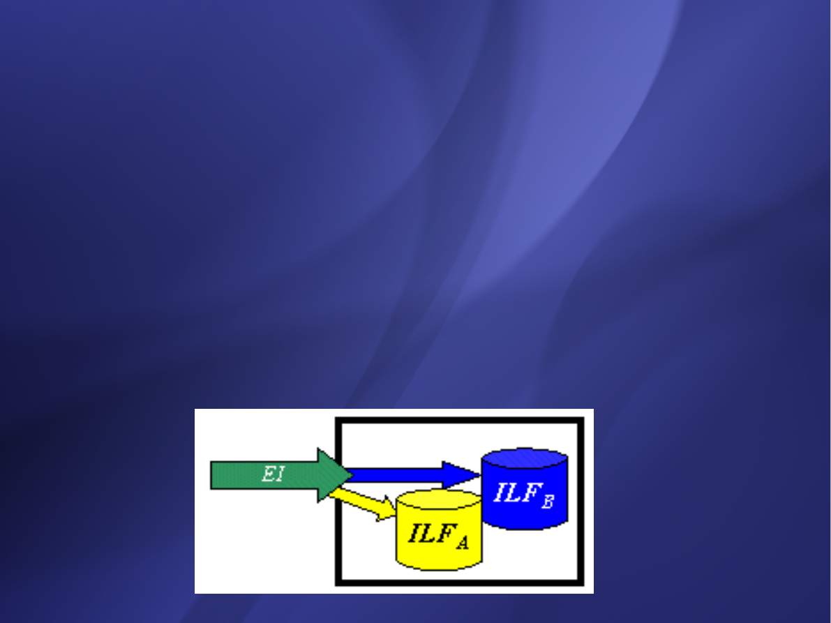
External Inputs (EI)
External Inputs (EI)
an elementary process in which data crosses the
an elementary process in which data crosses the
boundary from outside to inside. This data may come
boundary from outside to inside. This data may come
from a data input screen or another application. The
from a data input screen or another application. The
data may be used to maintain one or more internal
data may be used to maintain one or more internal
logical files. The data can be either control
logical files. The data can be either control
information or business information. If the data is
information or business information. If the data is
control information it does not have to update an
control information it does not have to update an
internal logical file.
internal logical file.
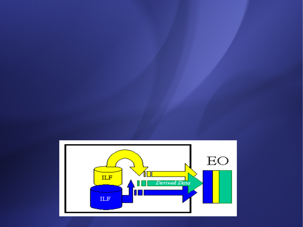
External Outputs (EO)
External Outputs (EO)
elementary process in which derived data passes
elementary process in which derived data passes
across the boundary from inside to outside.
across the boundary from inside to outside.
Additionally, an EO may update an ILF. The data
Additionally, an EO may update an ILF. The data
creates reports or output files sent to other
creates reports or output files sent to other
applications. These reports and files are created from
applications. These reports and files are created from
one or more internal logical files and external
one or more internal logical files and external
interface file.
interface file.
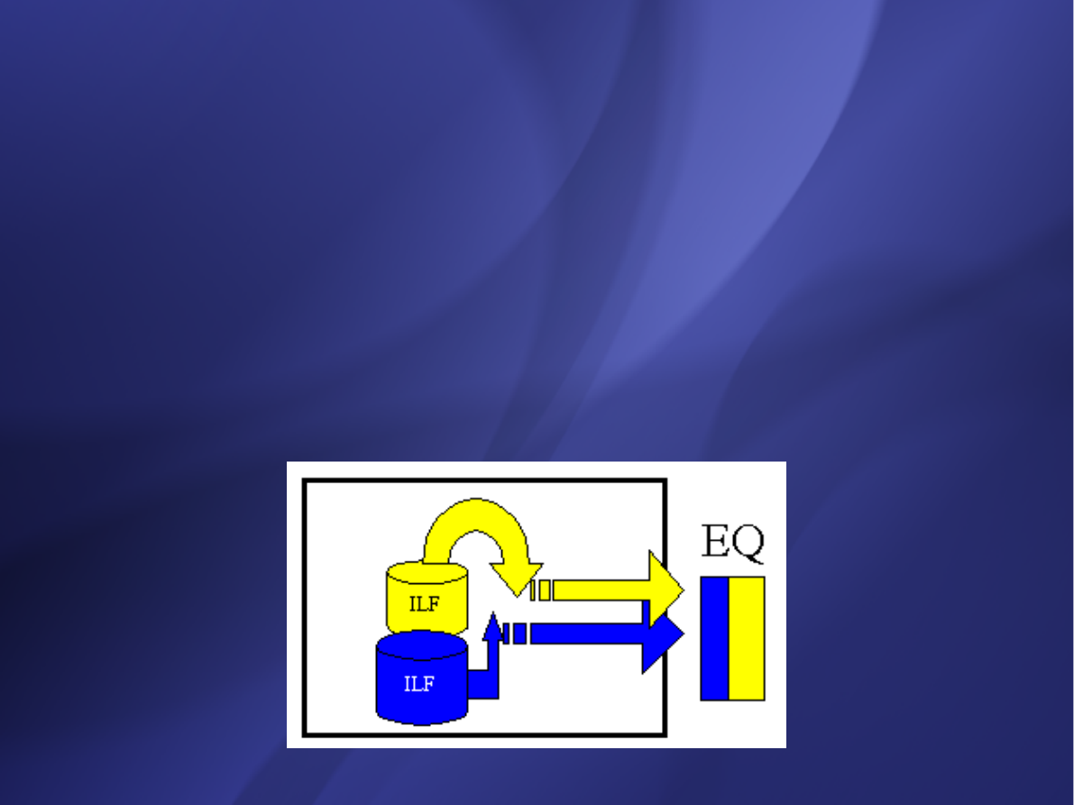
External Inquiry (EQ)
External Inquiry (EQ)
elementary process with both input and output
elementary process with both input and output
components that result in data retrieval from one or
components that result in data retrieval from one or
more internal logical files and external interface files.
more internal logical files and external interface files.
The input process does not update any Internal
The input process does not update any Internal
Logical Files, and the output side does not contain
Logical Files, and the output side does not contain
derived data. The graphic below represents an EQ
derived data. The graphic below represents an EQ
with two ILF's and no derived data.
with two ILF's and no derived data.

Internal Logical Files (ILF’s):
Internal Logical Files (ILF’s):
a user identifiable group of logically related
a user identifiable group of logically related
data that resides entirely within the
data that resides entirely within the
applications boundary and is maintained
applications boundary and is maintained
through external inputs.
through external inputs.
External Interface Files (EIF’s):
External Interface Files (EIF’s):
a user identifiable group of logically related
a user identifiable group of logically related
data that is used for
data that is used for
reference purposes
reference purposes
only
only
. The data resides
. The data resides
entirely outside the
entirely outside the
application
application
and is maintained by another
and is maintained by another
application. The external interface file is an
application. The external interface file is an
internal logical file for another application.
internal logical file for another application.

Functional Complexity
Functional Complexity
The first adjustment factor considers the Functional Complexity for
each unique function.
Functional Complexity is determined based on the combination of data
groupings and data elements of a particular function. The number of
data elements and unique groupings are counted and compared to a
complexity matrix that will rate the function as low, average or high
complexity. Each of the five functional components (ILF, EIF, EI, EO
and EQ) has its own unique complexity matrix. The following is the
complexity matrix for External Outputs.
1-5 DETs 6 - 19 DETs 20+ DETs
0 or 1 FTRs L L
A
2 or 3 FTRs L
A H
4+ FTRs
A
H H
Complexity UFP
L (Low)
4
A (Average) 5
H (High)
7

Value Adjustment Factor - The Unadjusted Function Point count is multiplied by
Value Adjustment Factor - The Unadjusted Function Point count is multiplied by
the second adjustment factor called the Value Adjustment Factor. This factor
the second adjustment factor called the Value Adjustment Factor. This factor
considers the system's technical and operational characteristics and is
considers the system's technical and operational characteristics and is
calculated by answering 14 questions. The factors are:
calculated by answering 14 questions. The factors are:
1. Data Communications
1. Data Communications
The data and control information used in the application are sent or received
The data and control information used in the application are sent or received
over communication facilities.
over communication facilities.
2. Distributed Data Processing
2. Distributed Data Processing
Distributed data or processing functions are a characteristic of the application
Distributed data or processing functions are a characteristic of the application
within the application boundary.
within the application boundary.
3. Performance
3. Performance
Application performance objectives, stated or approved by the user, in either
Application performance objectives, stated or approved by the user, in either
response or throughput, influence (or will influence) the design, development,
response or throughput, influence (or will influence) the design, development,
installation and support of the application.
installation and support of the application.
4. Heavily Used Configuration
4. Heavily Used Configuration
A heavily used operational configuration, requiring special design
A heavily used operational configuration, requiring special design
considerations, is a characteristic of the application.
considerations, is a characteristic of the application.
5. Transaction Rate
5. Transaction Rate
The transaction rate is high and influences the design, development,
The transaction rate is high and influences the design, development,
installation and support.
installation and support.

6. On-line Data Entry
6. On-line Data Entry
On-line data entry and control information functions are provided in the application.
On-line data entry and control information functions are provided in the application.
7. End -User Efficiency
7. End -User Efficiency
The on-line functions provided emphasize a design for end-user efficiency.
The on-line functions provided emphasize a design for end-user efficiency.
8. On-line Update
8. On-line Update
The application provides on-line update for the internal logical files.
The application provides on-line update for the internal logical files.
9. Complex Processing
9. Complex Processing
Complex processing is a characteristic of the application.
Complex processing is a characteristic of the application.
10. Reusability
10. Reusability
The application and the code in the application have been specifically designed,
The application and the code in the application have been specifically designed,
developed and supported to be usable in other applications.
developed and supported to be usable in other applications.
11. Installation Ease
11. Installation Ease
Conversion and installation ease are characteristics of the application. A conversion and
Conversion and installation ease are characteristics of the application. A conversion and
installation plan and/or conversion tools were provided and tested during the system
installation plan and/or conversion tools were provided and tested during the system
test phase.
test phase.
12. Operational Ease
12. Operational Ease
Operational ease is a characteristic of the application. Effective start-up, backup and
Operational ease is a characteristic of the application. Effective start-up, backup and
recovery procedures were provided and tested during the system test phase.
recovery procedures were provided and tested during the system test phase.
13. Multiple Sites
13. Multiple Sites
The application has been specifically designed, developed and supported to be installed
The application has been specifically designed, developed and supported to be installed
at multiple sites for multiple organizations.
at multiple sites for multiple organizations.
14. Facilitate Change
14. Facilitate Change
The application has been specifically designed, developed and supported to facilitate
The application has been specifically designed, developed and supported to facilitate
change.
change.
Document Outline
- Slide 1
- Slide 2
- Slide 3
- Slide 4
- Slide 5
- Slide 6
- Slide 7
- Slide 8
- Slide 9
- Slide 10
- Slide 11
- Slide 12
- Slide 13
- Slide 14
- Slide 15
- Slide 16
- Slide 17
- Slide 18
- Slide 19
- Slide 20
- Slide 21
- Slide 22
- Slide 23
- Slide 24
- Slide 25
- Slide 26
- Slide 27
- Slide 28
- Slide 29
- Slide 30
- Slide 31
- Slide 32
- Slide 33
- Slide 34
- Slide 35
- Slide 36
- Slide 37
- Slide 38
- Slide 39
- Slide 40
- Slide 41
- Slide 42
- Slide 43
- Slide 44
- Slide 45
- Slide 46
- Slide 47
- Slide 48
- Slide 49
- Slide 50
Wyszukiwarka
Podobne podstrony:
BYT 2006 Software Life cycles & roles in project team v1
BYT 2006 Software Life cycles & roles in project team v2
BYT 2005 Software testing
BYT 2006 Testowanie oprogramowania
BYT 2006 Planowanie zadan i metody ich obrazowania v2
BYT 2006 Communication in Project Management
BYT 2004 Software Testing
BYT 2006 Planowanie zadan i metody ich obrazowania v1
BYT 2006 Quality in IT project
8 Project complexity estimation
TACHOPRO TACHO SOFTWARE COMPLETE KIT FOR CHEAP OBD2 OBD VW AUDI BMW MERCEDES SEAT SKODA FORD SOFTWAR
TACHOPRO TACHO SOFTWARE COMPLETE KIT FOR CHEAP OBD2 OBD VW AUDI BMW MERCEDES SEAT SKODA FORD SOFTWAR
Kolmogorov Complexity Estimates For Detection Of Viruses In Biologically Inspired Security Systems
TACHOPRO TACHO SOFTWARE COMPLETE KIT FOR CHEAP OBD2 OBD VW AUDI BMW MERCEDES SEAT SKODA FORD SOFTWAR
więcej podobnych podstron