
EI-65 Service Info SKYAZÚL RESOURCES
www.skyazul.com
Page 1
PAT EI-65 Error Code List
Error code
Reason
Action
11
Operating data in the buffered RAM
Turn on the system again and
adjust operating data
21
Crane parameters in the serial EPROM
incorrect
Re-calibrate the system
31
Wrong EPROM programming or EPROM
defective
Exchange EPROM
51
Short circuit min layer device term 11&12
Check minimum layer device
52
Cable break min layer device term 11&12
Check minimum layer device
53
Short circuit A2B -switch - 2 term 13&14
Check anti-two block system
54
Cable break A2B -switch - 2 term 13&14
Check anti-two block system
55
Short circuit A2B -switch - 1 term 9&10
Check anti-two block system
56
Cable break A2B -switch - 1 term 9&10
Check anti-two block system
•61
Load on the main hoist hook too big
Reduce load on main hoist
•63
Load on the auxiliary hoist hook too big
Reduce load on aux. Hoist
•71
Limit Length - Main - Boom - Max.
Decrease length limit
•72
Limit Length - Main - Boom - Min.
Increase length limit
•73
Limit WG - Main - Boom - Max.
Decrease main boom angle
•74
Limit WG - Main - Boom - Min.
Increase main boom angle
•75
Limit Boom height - Max.
Decrease main boom angle
•76
Limit Boom height - Min.
Increase main boom angle
•77
Limit Working radius - Max.
Increase main boom angle
•78
Limit Working radius - Min.
Decrease main boom angle
81
ADC-Measuring value KMD1 too big
Check zero point in linerider
82
ADC-Measuring value KMD1 too low
Check zero point in linerider
83
ADC-Measuring value KMD2 too big
Check zero point in linerider
84
ADC-Measuring value KMD2 too low
Check zero point in linerider
93
ADC-Measuring value WG1 too big
Check main angle sensor circuit
94
ADC-Measuring value WG1 too low
Check main angle sensor circuit
95
ADC-Measuring value WG2 too big
Check luffing angle sensor circuit
96
ADC-Measuring value WG2 too low
Check luffing angle sensor circuit
EI-65 Service Info SKYAZÚL RESOURCES
www.skyazul.com
Page 2
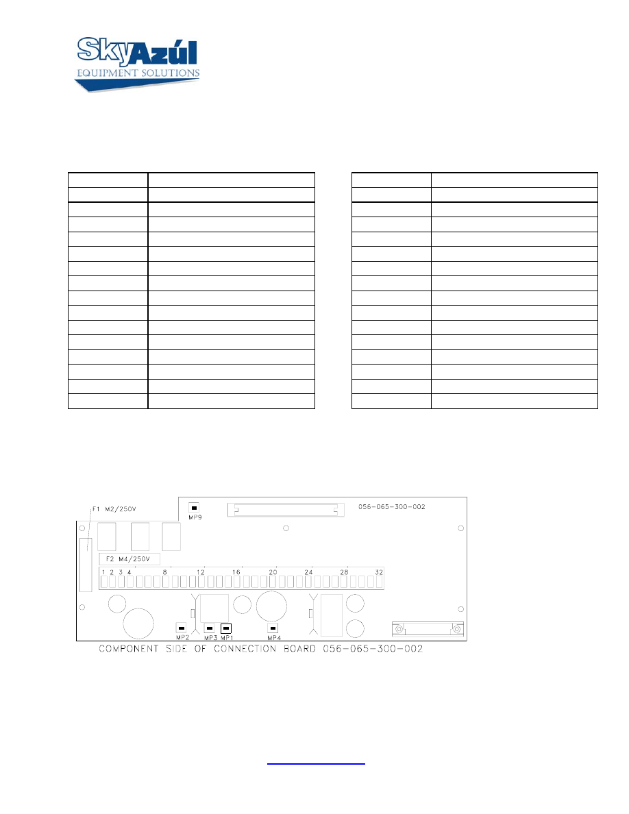
Connection Board 056-065-300-002 Designations:
1 +
Battery
17 +5VDC
2 +
Battery
18
Main Boom angle input
3 -
Battery
19
Main Boom Length input
4 -
Battery
20 Analog
Ground
5
Load Limit output
21 +5VDC
6
A2B Relay output 2
22
Jib Angle input
7
A2B Relay output 1
23 Analog
Ground
8 Peripheral
ground
24 Analog
Ground
9
A2B 1 input
25 +9VDC
10 A2B
Ground
26
KMD1 +Signal input
11
A2B 2 input
27
KMD1 -Signal input
12 A2B
Ground
28 -9VDC
13
3rd Wrap Switch input
29 +9VDC
14
3rd Wrap Switch ground
30
KMD2 +Signal input
15
Digital input 1
31
KMD2 -Signal input
16
Digital input 2
32 -9VDC
•
DRAWING 2. CONNECTION BOARD LAYOUT
MP1 = GND
MP2 = 5.6V
MP3 = 5.6V
MP4 = .5V min sig.
To 4.5V max sig.
EI-65 Service Info SKYAZÚL RESOURCES
www.skyazul.com
Page 3
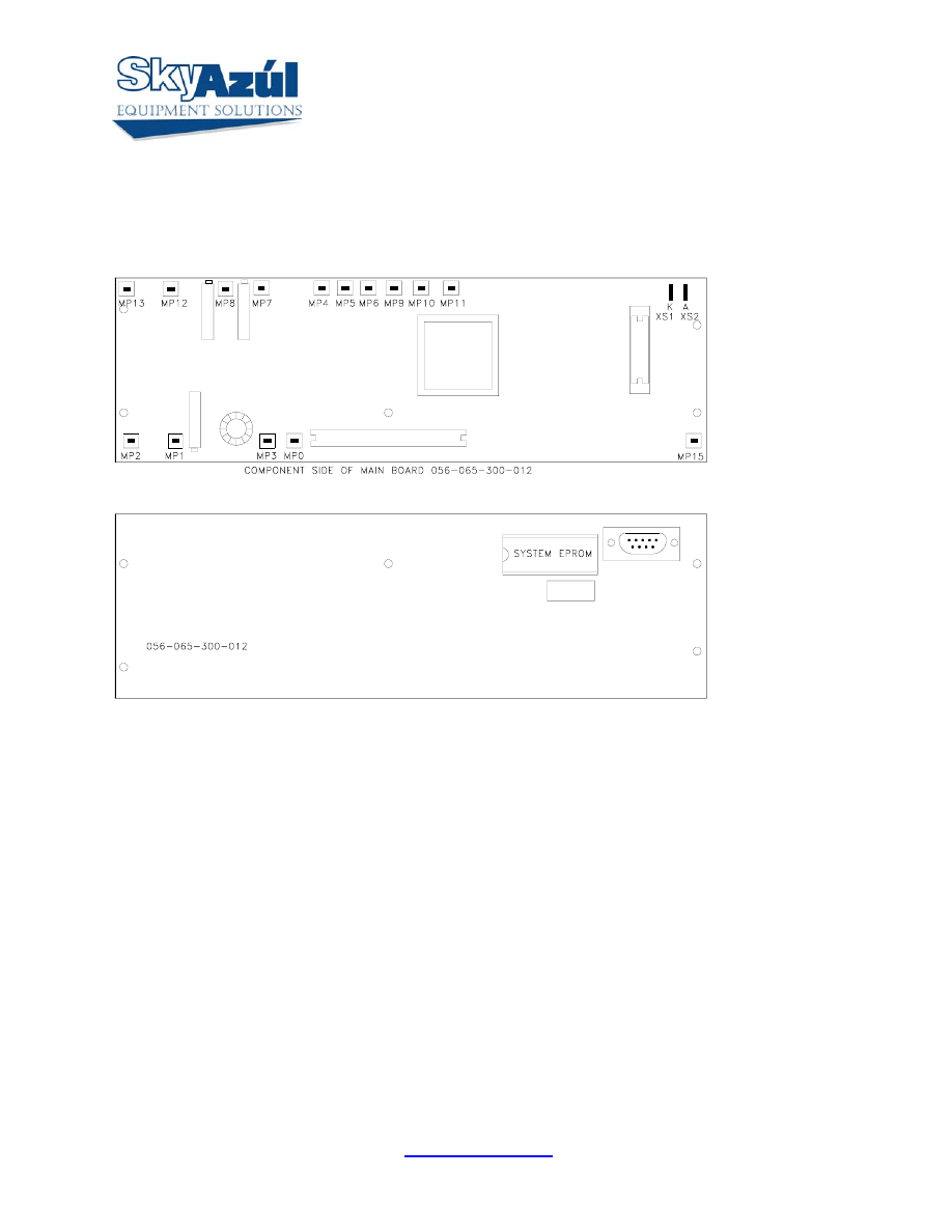
DRAWING 3. MAIN BOARD LAYOUT
MP0 = GND
MP1 = AGND
MP2 = +5.0V
MP3 = +5.0V
MP4 = SIGNAL, LENGTH CHANNEL
MP5 = SIGNAL, ANGLE 2
MP6 = SIGNAL, ANGLE 1
MP7 = SIGNAL, KMD1
MP8 = SIGNAL, KMD2
MP9 = AN5 REFERENCE VOLATGE
MP10 = AN6 REFERENCE VOLTAGE
MP11 = AN7 REFERENCE VOLTAGE
MP12 = -0.5V
MP13 = +5.0V
MP15 = 5.2
Wyszukiwarka
Podobne podstrony:
BMW E6x Code List
ERROR CODE CZYLI SPIS ERRORów XBOX 360
BMW E46 Code List Code
001A BY Extended fail safe P code list
BMW E9x Code List
E90 Code List
BMW E6x Code List
BMW E9x Code List v1edit
BMW E9x Code List v1 E9x Code List
c wxSmith and Code Blocks build error Stack Overflow
ei 01 2002 s 65
ei 07 2002 s 65 68
immo universal decoding remove the immo code of ecu support car list
ei 06 2003 s62 65
ei 02 2003 s62 65
ei 07 2002 s 65 68
więcej podobnych podstron