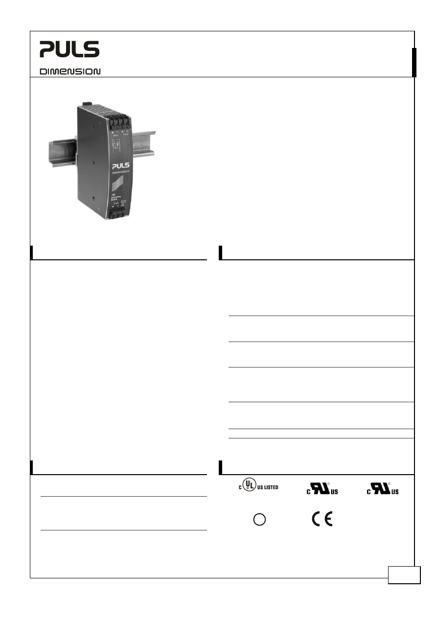
YR2.DIODE
Y-Series
10-60V, 20A, D
UAL
D
ECOUPLING
M
ODULE
Nov 2006 / Rev. 1.0 DS-YR2.DIODE-EN
All parameters are specified at 24V, 20A output current, 25°C ambient and after a 5 minutes run-in time unless otherwise noted.
www.pulspower.com Phone +49 89 9278 0 Germany
1/16
D
ECOUPLING
M
ODULE
■
Dual input, single output
■
Two diodes (common cathode)
■
Rugged metal housing
■
Width only 32mm
■
Cost effective solution to build redundant systems
■
10-60V Wide-range input
■
20A Continuous output current
■
Easy wiring;
Distribution terminals for negative pole included
■
Quick-connect spring-clamp terminals
■
3 Year warranty
1. G
ENERAL
D
ESCRIPTION
2. S
HORT
-
FORM
D
ATA
Input voltage
DC 24V
Input voltage range
10-60Vdc
Input current
2x 12.5A
1+1 Redundancy
2x 10A
N+1 Redundancy
1x
20A
Single
use
Output current
max. 20A
Normal mode
max. 25A
Overload / short-
circuit
Input to output
voltage drop
typ. 0.85V
At 20A output
current
Power losses
0 W
At no load
17W
At 20A output
current
Temperature range
-25°C to +70°C
Operational
Derating
0.5A/°C
+60 to +70°C
The YR2.DIODE is a decoupling module, which can
be used for various purposes. The most popular
application is to configure a highly reliable and true
redundant power supply systems.
Another interesting application is the separation of
sensitive loads from non-sensitive loads. This avoids
the distortion of the power quality for the sensitive
loads which can cause controller failures.
The YR2.DIODE is the perfect solution to use in a
redundant system, if the power supply itself is
equipped with a DC-OK signal (e.g.: DIMENSION Q-
Series).
Alongside with the YR2.DIODE, there exists the
YRM2.DIODE which has a monitoring circuitry
included. LEDs and relay contacts signal when one of
the two DC-input voltages is not in range due to a
non-functioning power supply.
Unique quick-connect spring-clamp terminals allow a
safe and fast installation and a large international
approval package for a variety of applications makes
this unit suitable for nearly every situation.
Dimensions 32x124x102mm
WxHxD
3. O
RDER
N
UMBERS
4. M
ARKINGS
Decoupling
Module
YR2.DIODE
Dual input / single
output
IND. CONT. EQ.
UL 508
UL 60950-1
Class I Div 2
ZM1.WALL
Wall / panel mount
bracket
Accessory
ZM11.SIDE Side
mount
bracket
GL
Marine
EMC, LVD
YR2.DIODE
Y-Series
10-60V, 20A, D
UAL
D
ECOUPLING
M
ODULE
Nov 2006 / Rev. 1.0 DS-YR2.DIODE-EN
All parameters are specified at 24V, 20A output current, 25°C ambient and after a 5 minutes run-in time unless otherwise noted.
www.pulspower.com Phone +49 89 9278 0 Germany
2/16
I
NDEX
P
AGE
I
NDEX
P
AGE
1.
General Description ............................................1
2.
Short-form Data ..................................................1
3.
Order Numbers....................................................1
4.
Markings ..............................................................1
5.
Input and Output Characteristics .......................3
6.
Power Losses........................................................4
7.
Reliability .............................................................4
8.
Functional Diagram.............................................5
9.
Front Side and User Elements.............................5
10.
Terminals and Wiring..........................................6
11.
EMC......................................................................6
12.
Environment ........................................................7
13.
Protection Features .............................................8
14.
Safety ...................................................................8
15.
Dielectric Strength ..............................................8
16.
Approvals.............................................................9
17.
Fulfilled Standards.............................................. 9
18.
Used Substances ................................................. 9
19.
Physical Dimensions and Weight ..................... 10
20.
Installation and Operation Instructions .......... 10
21.
Accessory........................................................... 11
22.
Application Notes............................................. 12
22.1.
Recommendations for Redundancy ...... 12
22.2.
1+1 Redundancy up to 10A ................... 12
22.3.
1+1 Redundancy up to 20A ................... 13
22.4.
N+1 Redundancy, Example with 20A .... 13
22.5.
Battery Back-up ...................................... 14
22.6.
Redundancy for Sensitive Loads ............ 14
22.7.
Decoupling of Buffered Branches ......... 15
22.8.
Use in a Tightly Sealed Enclosure .......... 15
22.9.
Mounting Orientations .......................... 16
I
NTENDED
U
SE
The decoupling module shall only be installed and put into operation by qualified personnel.
This decoupling module is designed for installation in an enclosure and is intended for the general use, such as in
industrial control, office, communication, and instrumentation equipment. Do not use this device in aircraft, trains
and nuclear equipment, where malfunctioning of the power supply may cause severe personal injury or threaten
human life.
T
ERMINOLOGY AND
A
BREVIATIONS
PE and
symbol
PE is the abbreviation for Protective Earth and has the same meaning as the symbol
.
Earth, Ground
This document uses the term “earth” which is the same as the U.S. term “ground”.
T.b.d.
To be defined, value or description will follow later.
DC 24V
A figure displayed with the AC or DC before the value represents a nominal voltage with
standard tolerances (usually ±20%) included.
E.g.: DC 12V describes a 12V battery disregarding whether it is full (13.7V) or flat (10V)
24Vac
A figure with the unit (Vac) at the end is a momentary figure without any additional
tolerances included.
D
ISCLAIMER
The information presented in this document is believed to be accurate and reliable and may change without notice.
YR2.DIODE
Y-Series
10-60V, 20A, D
UAL
D
ECOUPLING
M
ODULE
Nov 2006 / Rev. 1.0 DS-YR2.DIODE-EN
All parameters are specified at 24V, 20A output current, 25°C ambient and after a 5 minutes run-in time unless otherwise noted.
www.pulspower.com Phone +49 89 9278 0 Germany
3/16
5. I
NPUT AND
O
UTPUT
C
HARACTERISTICS
Number of inputs
nom.
2
Number of outputs
nom.
1
Input
voltage
nom.
DC 24V
Input
voltage
range
-
10-60Vdc
Voltage drop, input to output
typ.
0.85V
At 2x10A, see
Fig. 5-1
Input
current
max.
2x 12.5A
Continuous, 1+1 Redundancy, see
Fig. 5-2
max.
2x 10A
Continuous, N+1 Redundancy, see
Fig. 5-3
max.
1x 20A
Continuous, Single use, see
Fig. 5-4
Input
current
max.
2x 18.5A
Up to 5s, 1+1 Redundancy, continuous, see
Fig. 5-2
max.
2x 15A
Up to 5s, N+1 Redundancy, continuous, see
Fig. 5-3
max.
1x 30A
Up to 5s, Single use, continuous, see
Fig. 5-4
Peak input current
max.
150A
Max. 10ms, per input
Output
current
max.
20A / 30A
Normal mode, continuous / up to 5s
max.
25A / 37.5A
At overload or short-circuit, continuous / up to 5s
Reverse current
max.
2mA
Per input, -25°C to +60°C
Reverse voltage
max.
200Vdc
Voltage applied to the output, continuously allowed
Note: Ensure that the continuous output current does not exceed 25A. Check the short-circuit current of the power
sources and if the power source can deliver more than 25A, use an appropriate fuse on the output.
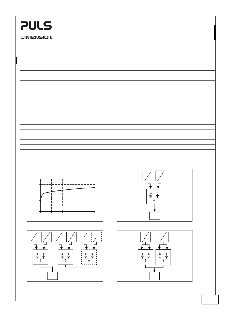
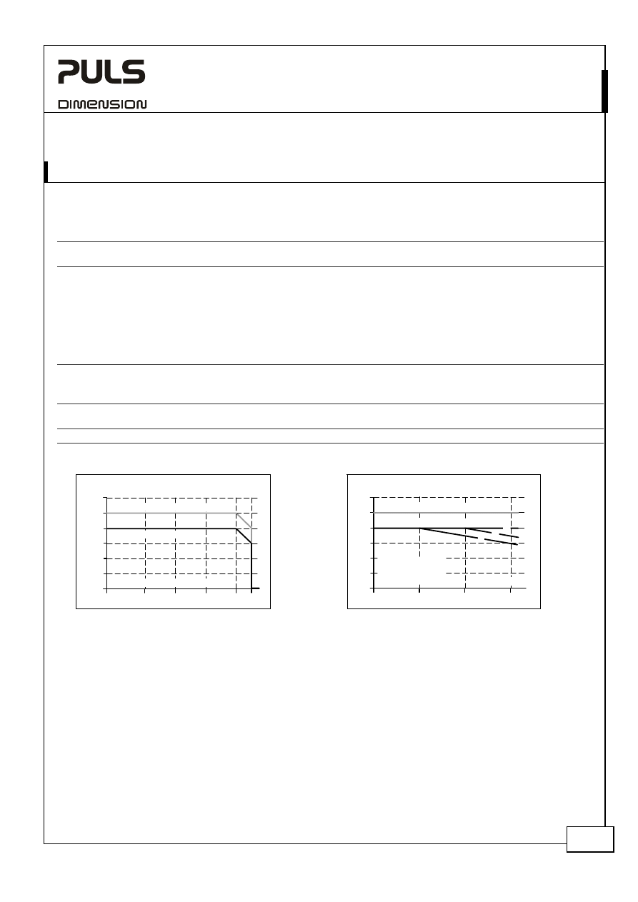
Fig. 5-1 Voltage Drop
Fig. 5-2 1+1 Redundancy
Input to Output Voltage Drop, typ.
0
0
5
10
20
0.2
0.4
0.6
0.8
1.0
1.2V
25A
15
Output Current
AC
DC
AC
DC
Load
+
-
IN 1
OUT
IN 2
Fig. 5-3 N+1 Redundancy
Fig. 5-4 Single use (redundant)
AC
DC
AC
DC
AC
DC
AC
DC
AC
DC
AC
DC
IN 1
OUT
IN 2
IN 1
OUT
IN 2
IN 1
OUT
IN 2
Load
+
-
Load
+
-
IN 1
OUT
IN 2
AC
DC
AC
DC
IN 1
OUT
IN 2
YR2.DIODE
Y-Series
10-60V, 20A, D
UAL
D
ECOUPLING
M
ODULE
Nov 2006 / Rev. 1.0 DS-YR2.DIODE-EN
All parameters are specified at 24V, 20A output current, 25°C ambient and after a 5 minutes run-in time unless otherwise noted.
www.pulspower.com Phone +49 89 9278 0 Germany
4/16
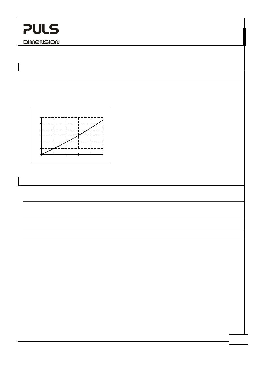
6. P
OWER
L
OSSES
Power
losses
typ.
3.6W
10-60Vdc, 5A output current, see
Fig. 6-1
typ.
7.85W
10-60Vdc, 10A output current, see
Fig. 6-1
typ.
17.0W
10-60Vdc, 20A output current, see
Fig. 6-1
Fig. 6-1 Power losses vs. output current
Power Losses, typ.
0
0
5
10
20
4
8
12
16
20
24W
25A
15
Output Current
7. R
ELIABILITY
DC 24V
Lifetime expectancy
min.
> 25 years
40°C, input: 2x10A, output: 20A, no electrolytic capacitors involved
min.
> 25 years
40°C, input: 2x5A, output: 10A, no electrolytic capacitors involved
min.
> 25 years
25°C, input: 2x10A, output: 20A, no electrolytic capacitors involved
MTBF SN 29500, IEC 61709
46 500 000h
40°C, input: 2x10A, output: 20A
70 000 000h
25°C, input: 2x10A, output: 20A
MTBF MIL HDBK 217F
36 200 000h
40°C, input: 2x10A, output: 20A, Ground Benign GB40
41 100 000h
25°C, input: 2x10A, output: 20A, Ground Benign GB25
The Lifetime expectancy shown in the table indicates the operating hours (service life) and is determined by the
lifetime expectancy of the built-in electrolytic capacitors.
Lifetime expectancy is specified in operational hours. Lifetime expectancy is calculated according to the capacitor’s
manufacturer specification. The prediction model allows a calculation of up to 15 years from date of shipment.
MTBF stands for Mean Time Between Failure, which is calculated according to statistical device failures, and indicates
reliability of a device. It is the statistical representation of the likelihood of the unit to fail and does not necessarily
represent the life of a product.
YR2.DIODE
Y-Series
10-60V, 20A, D
UAL
D
ECOUPLING
M
ODULE
Nov 2006 / Rev. 1.0 DS-YR2.DIODE-EN
All parameters are specified at 24V, 20A output current, 25°C ambient and after a 5 minutes run-in time unless otherwise noted.
www.pulspower.com Phone +49 89 9278 0 Germany
5/16
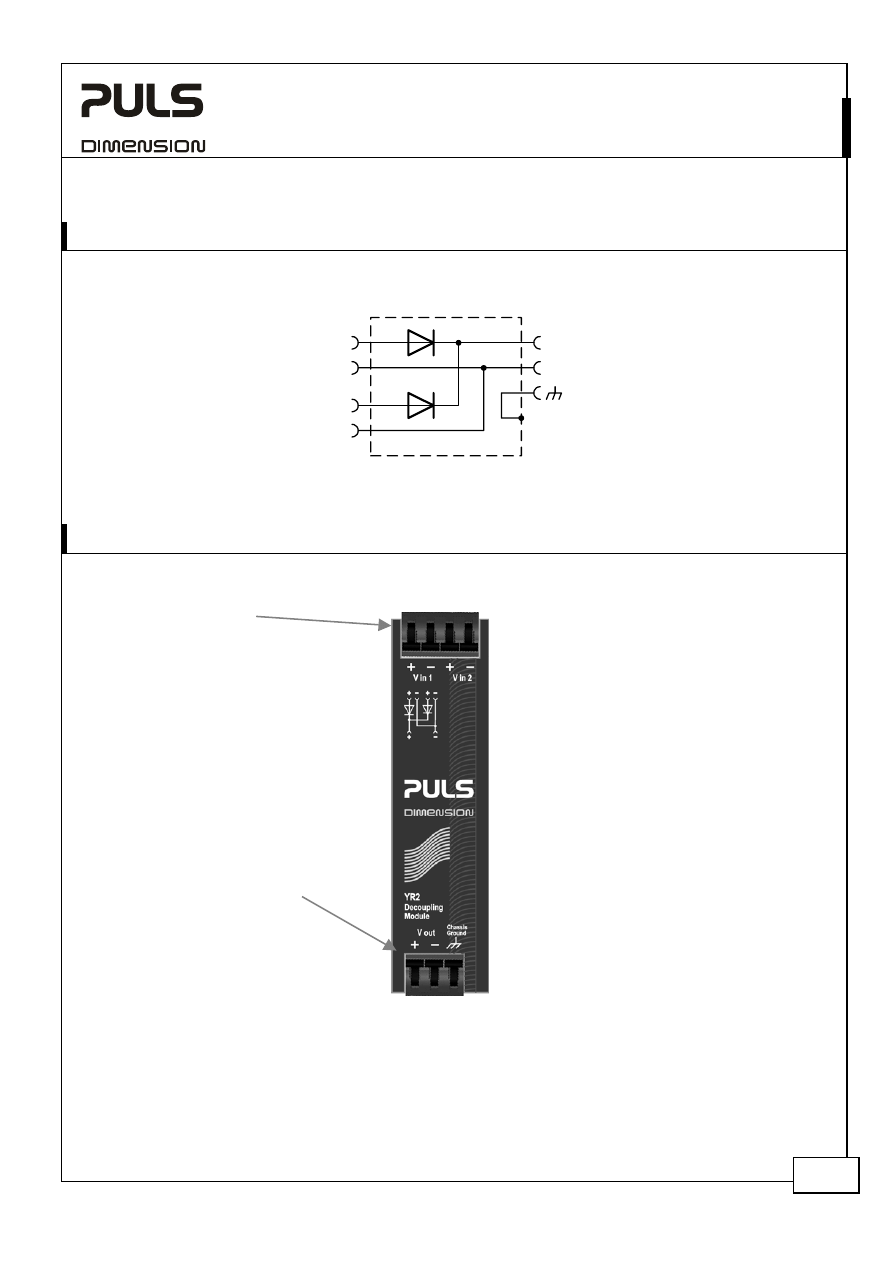
8. F
UNCTIONAL
D
IAGRAM
Fig. 8-1 Functional diagram
+
-
+
-
+
-
Chassis
Ground
V
OUT
V
IN
1
V
IN
2
9. F
RONT
S
IDE AND
U
SER
E
LEMENTS
Fig. 9-1 Front side
Input Terminals
Quick-connect spring-clamp
terminals, no tools required
+ Positive input
- Negative (return) input
Output Terminals
Quick-connect spring-clamp
terminals, no tools required
+ Positive output
- Negative (return) output
Chassis ground….
Optionally to connect to PE
See chapter 10 “Terminals and Wiring” to
choose appropriate wire gauges
YR2.DIODE
Y-Series
10-60V, 20A, D
UAL
D
ECOUPLING
M
ODULE
Nov 2006 / Rev. 1.0 DS-YR2.DIODE-EN
All parameters are specified at 24V, 20A output current, 25°C ambient and after a 5 minutes run-in time unless otherwise noted.
www.pulspower.com Phone +49 89 9278 0 Germany
6/16
10. T
ERMINALS AND
W
IRING
Type
Bi-stable,
quick-connect spring clamp terminals. IP20 Finger safe construction.
Suitable for field- and factory installation. Shipped in open position.
Solid
wire
0.5-6mm
2
Stranded
wire
0.5-4mm
2
American wire gauge
20-10 AWG
Ferrules
Allowed, but not required
Wire stripping length
10mm / 0.4inch
Pull-out force
10AWG:80N, 12AWG:60N, 14AWG:50N, 16AWG:40N (according to UL486E)
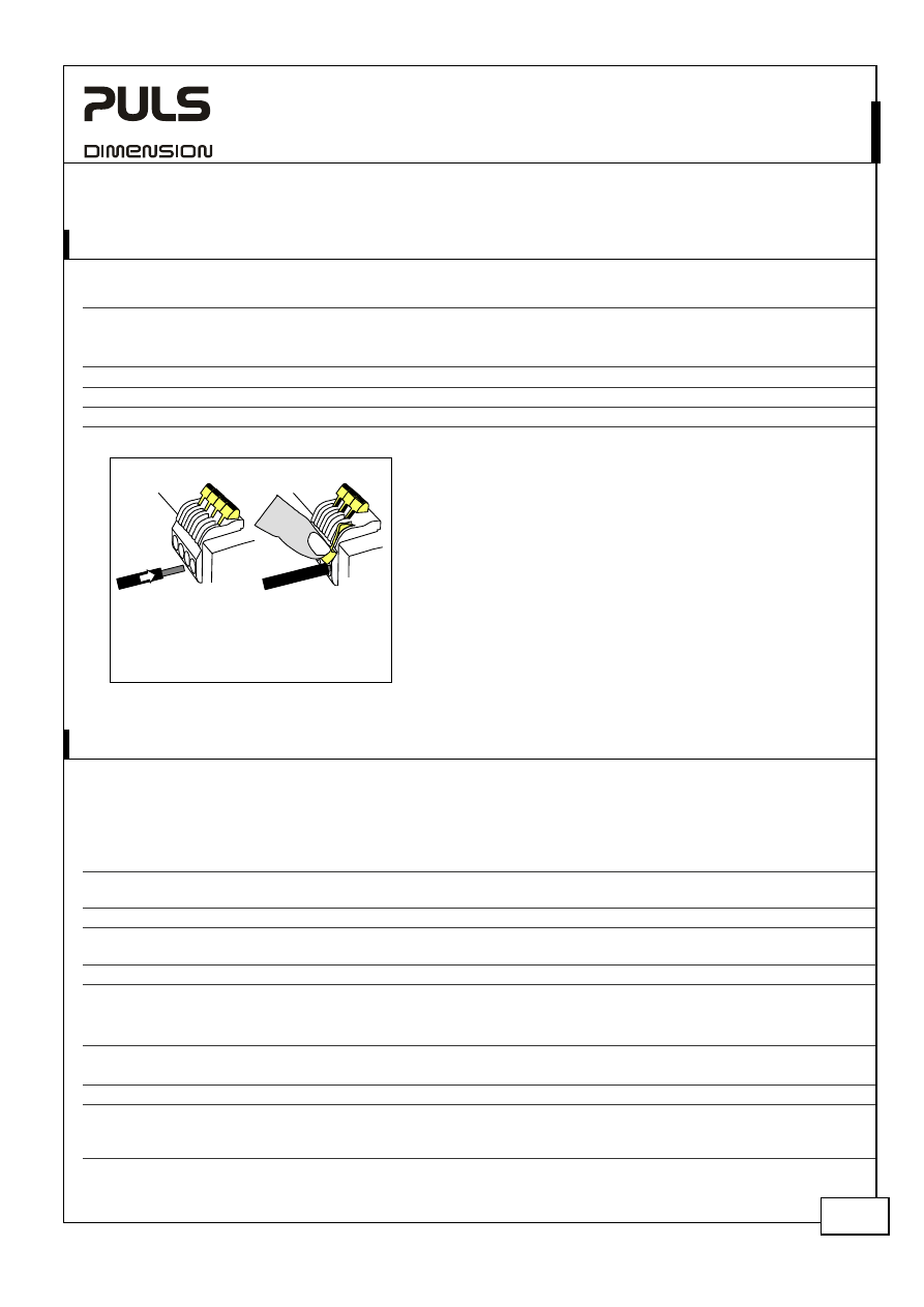
Fig. 10-1 Connecting a wire
1. Insert the wire
2. Snap the lever
To disconnect wire: same procedure
vice versa
Instructions:
a)
Use appropriate copper cables that are designed
for an operating temperature of:
60°C for ambient up to 45°C and
75°C for ambient up to 60°C minimum.
b)
Follow national installation codes and
installation regulations!
c)
Ensure that all strands of a stranded wire enter
the terminal connection!
d)
Up to two stranded wires with the same cross
section are permitted in one connection point
(except PE wire).
e)
Do not use the unit without PE connection.
11. EMC
The decoupling module is suitable for applications in industrial environment as well as in residential, commercial and
light industry environment without any restrictions. CE mark is in conformance with EMC guideline 89/336/EEC and
93/68/EEC and the low-voltage directive (LVD) 73/23/EWG. A detailed EMC Report is available upon request
EMC Immunity
EN 61000-6-1 EN 61000-6-2
Generic standards
Electrostatic discharge
EN 61000-4-2
Contact discharge
Air discharge
8kV
15kV
Criterion A
Criterion A
Electromagnetic RF field
EN 61000-4-3 80MHz-1GHz
10V/m
Criterion
A
Fast transients (Burst)
EN 61000-4-4
Input
Output
2kV
2kV
Criterion A
Criterion A
Conducted disturbance
EN 61000-4-6
0.15-80MHz
10V
Criterion A
Criterions:
A: Device shows normal operation behavior within the defined limits.
EMC Emission
EN 61000-6-3 and EN 61000-6-4
Generic standards
Conducted emission
EN 55011, EN 55022, FCC Part 15, CISPR 11, CISPR 22
Class B, input lines
EN 55022
Class B, output lines
Radiated emission
EN 55011, EN 55022
Class B
This device complies with FCC Part 15 rules.
Operation is subjected to following two conditions: (1) this device may not cause harmful interference, and (2) this
device must accept any interference received, including interference that may cause undesired operation.
YR2.DIODE
Y-Series
10-60V, 20A, D
UAL
D
ECOUPLING
M
ODULE
Nov 2006 / Rev. 1.0 DS-YR2.DIODE-EN
All parameters are specified at 24V, 20A output current, 25°C ambient and after a 5 minutes run-in time unless otherwise noted.
www.pulspower.com Phone +49 89 9278 0 Germany
7/16
12. E
NVIRONMENT
Operational temperature
-25°C to +70°C (-13°F to 158°F)
Reduce output power above +60°C
Output de-rating
0.5A/°C
60-70°C (140°F to 158°F), see
Fig. 12-1
Storage temperature
-40°C to +85°C (-40°F to 185°F)
Storage and transportation
Humidity
5 to 95% r.H.
IEC 60068-2-30
Do not energize while condensation is present
Vibration sinusoidal
2-17.8Hz: ±1.6mm;
17.8-500Hz: 2g
2 hours / axis
IEC 60068-2-6
Vibration
random
0.5m
2
(s
3
)
2 hours / axis
IEC 60068-2-64
Shock
30g 6ms, 20g 11ms
3 bumps / direction,
18 bumps in total
IEC 60068-2-27
Altitude
0 to 6000m (0 to 20 000ft)
Reduce output power or ambient temperature
above 2000m sea level.
Output de-rating (for altitude)
1.25A/1000m or 5°C/1000m
Above 2000m (6500ft), see
Fig. 12-2
Over-voltage
category
III
EN 50178,
(for clearance and creepage distances)
Degree of pollution
2
EN 50178, not conductive
Fig. 12-1 Output current vs. ambient temp.,
Fig. 12-2 Output current vs. altitude
Allowed Output Current
0
-25
0
20
40
70°C
5
10
15
20
25
30A
normal mode
60
Ambient Temperature
overload / short circuit
Allowed Output Current
0
0
2000
4000
6000m
5
10
15
20
25
30A
normal mode
Altitude
overload / short circuit
A... Tamb < 60°C
B... Tamb < 50°C
C... Tamb < 40°C
A
B
C
The ambient temperature is defined as the air temperature 2cm below the unit.
YR2.DIODE
Y-Series
10-60V, 20A, D
UAL
D
ECOUPLING
M
ODULE
Nov 2006 / Rev. 1.0 DS-YR2.DIODE-EN
All parameters are specified at 24V, 20A output current, 25°C ambient and after a 5 minutes run-in time unless otherwise noted.
www.pulspower.com Phone +49 89 9278 0 Germany
8/16
13. P
ROTECTION
F
EATURES
Output
over-current
protection not
included
Degree of protection
IP 20
EN/IEC 60529
Penetration protection
> 3.5mm
E.g. screws, small parts
Over-temperature
protection
no
Input transient protection
no
Internal input fuse
not included
Note: In case of a protection event, audible noise may occur.
14. S
AFETY
Input / output separation
200V Epitaxial diode
Class of protection
III
PE (Protective Earth) connection not mandatory
PE resistance
< 0.1Ohm
Between housing and PE terminal
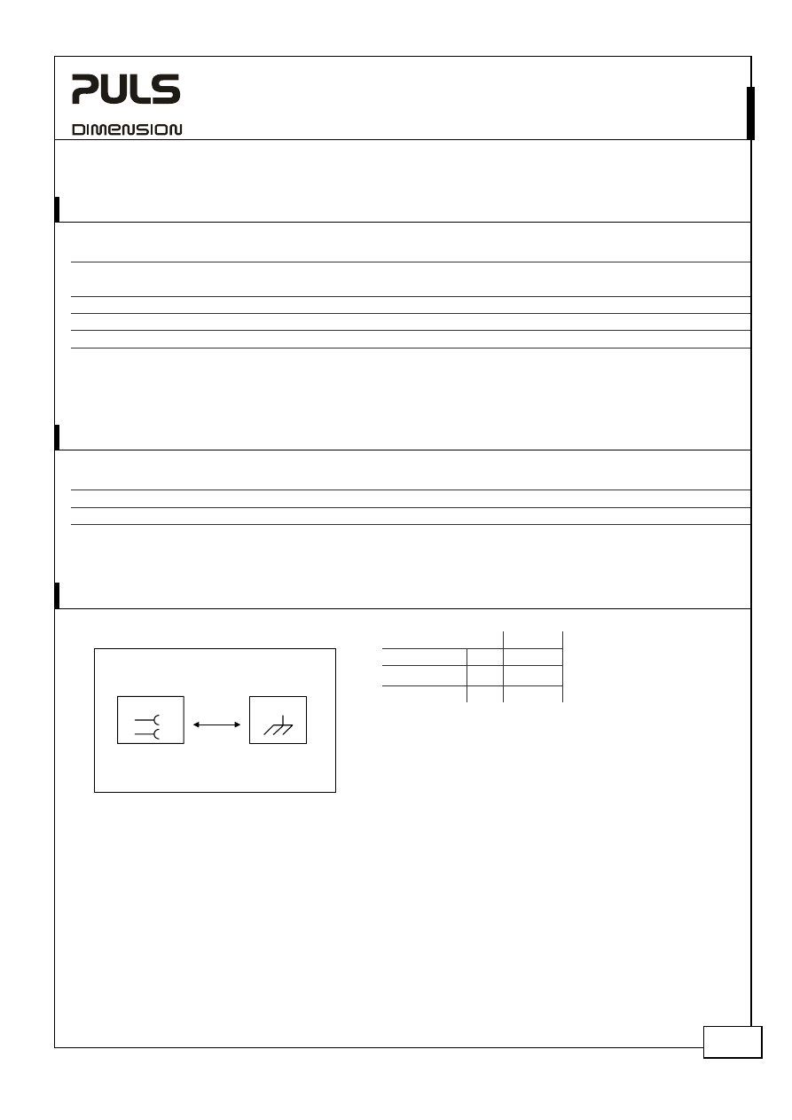
15. D
IELECTRIC
S
TRENGTH
Fig. 15-1 Dielectric strength
A
Type test
60s
500Vac
Factory test
5s
500Vac
Field test
5s
500Vac
A
Chassis
In- / Output
-
+
Type tests and factory tests:
Conducted by the manufacturer. Do not repeat test in field!
Rules for field test:
Use appropriate test equipment which applies the voltage
with a slow ramp!
During testing, connect all output and input poles together.
The input and output voltage is floating and has no ohmic connection to ground.
YR2.DIODE
Y-Series
10-60V, 20A, D
UAL
D
ECOUPLING
M
ODULE
Nov 2006 / Rev. 1.0 DS-YR2.DIODE-EN
All parameters are specified at 24V, 20A output current, 25°C ambient and after a 5 minutes run-in time unless otherwise noted.
www.pulspower.com Phone +49 89 9278 0 Germany
9/16
16. A
PPROVALS
UL
508
IND. CONT. EQ.
LISTED E198865 listed for use in U.S.A. (UL 508) and Canada (C22.2
No. 14-95)
Industrial Control Equipment
UL
60950-1
RECOGNIZED E137006 recognized for the use in U.S.A. (UL 60950-
1) and Canada (C22.2 No. 60950)
Information Technology Equipment
UL
1604
RECOGNIZED E246877 recognized for use in U.S.A. (UL 1604) and
Canada (C22.2 No. 213-M1987)
Hazardous Location Class I Div 2 T4 Groups A,B,C,D and
Class I Zone 2 Groups IIA, IIB and IIC
The unit is suitable for use in Class I Division 2 Groups A, B, C, D locations as well as for Class I
Zone 2 Groups IIA, IIB and IIC locations. Substitution of components may impair suitability for
Class I Division 2 environment. Do not disconnect equipment unless power has been switched
off. Wiring must be in accordance with Class I, Division 2 wiring methods of the National
Electrical Code, NFPA 70, and in accordance with other local or national codes.
Marine
GL
ABS
GL (Germanischer Lloyd) classified and ABS (American Bureau for
Shipping) PDA for marine and offshore applications.
Environmental category: C, EMC2
17. F
ULFILLED
S
TANDARDS
EN/IEC 60204-1
Safety of Electrical Equipment of Machines
EN/IEC 61131-2
Programmable Controllers
EN 50178
Electronic Equipment in Power Installations
18.
U
SED
S
UBSTANCES
The unit does not release any silicone and is suitable for the use in paint shops.
Electrolytic capacitors included in this unit do not use electrolytes such as Quaternary Ammonium Salt Systems.
Plastic housings and other molded plastic materials are free of halogens, wires and cables are not PVC insulated.
The production material within our production does not include following toxic chemicals:
Polychlorized Biphenyl (PCB), Polychlorized Terphenyl (PCT), Pentachlorophenol (PCP), Polychlorinated naphthalene
(PCN), Polybrom Biphenyll (PBB), Polybrom Bipheny-oxyd (PBO), Polybrominated Diphenylether (PBDE), Polychlorinated
Diphenylether (PCDE), Polydibromphenyl Oxyd (PBDO), Cadmium, Asbest, Mercury, Silicia
YR2.DIODE
Y-Series
10-60V, 20A, D
UAL
D
ECOUPLING
M
ODULE
Nov 2006 / Rev. 1.0 DS-YR2.DIODE-EN
All parameters are specified at 24V, 20A output current, 25°C ambient and after a 5 minutes run-in time unless otherwise noted.
www.pulspower.com Phone +49 89 9278 0 Germany
10/16
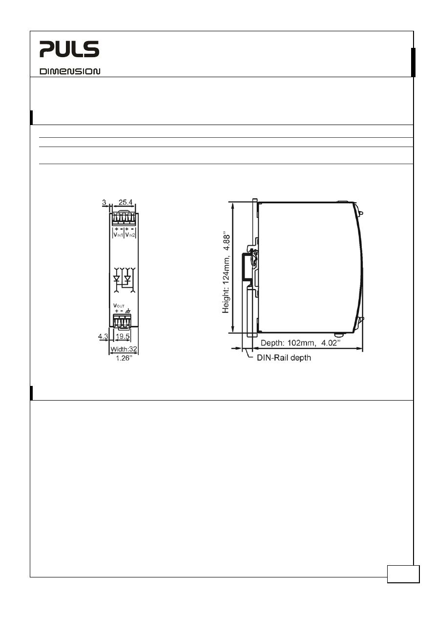
19. P
HYSICAL
D
IMENSIONS AND
W
EIGHT
Weight
290g / 0.64lb
DIN-Rail
Use 35mm DIN-rails according to EN 60715 or EN 50022 with a height of 7.5 or 15mm.
The DIN-rail height must be added to the depth (102mm) to calculate the total required installation depth.
Electronic files with mechanical data can be downloaded at www.pulspower.com
Fig. 19-1 Front view
Fig. 19-2 Side view
20. I
NSTALLATION AND
O
PERATION
I
NSTRUCTIONS
Mounting Orientation:
Input terminal must be located on top and output terminal on the bottom. For other orientations see section 22.9
Cooling:
Convection cooled, no forced cooling required. Do not cover ventilation grid (e.g. cable conduits) by more than 30%!
Installation clearances:
40mm on top, 20mm on the bottom, 5mm on the left and right side are recommended when loaded permanently
with full power. In case the adjacent device is a heat source, 15mm clearance is recommended.
Risk of electrical shock, fire, personal injury or death!
Turn power off before working on the module. Protect against inadvertent re-powering.
Make sure the wiring is correct by following all local and national codes.
Do not open, modify or repair the unit.
Use caution to prevent any foreign objects from entering into the housing.
Do not use in wet locations or in areas where moisture or condensation can be expected.
Service parts:
The unit does not contain any serviceable parts.
YR2.DIODE
Y-Series
10-60V, 20A, D
UAL
D
ECOUPLING
M
ODULE
Nov 2006 / Rev. 1.0 DS-YR2.DIODE-EN
All parameters are specified at 24V, 20A output current, 25°C ambient and after a 5 minutes run-in time unless otherwise noted.
www.pulspower.com Phone +49 89 9278 0 Germany
11/16
21. A
CCESSORY
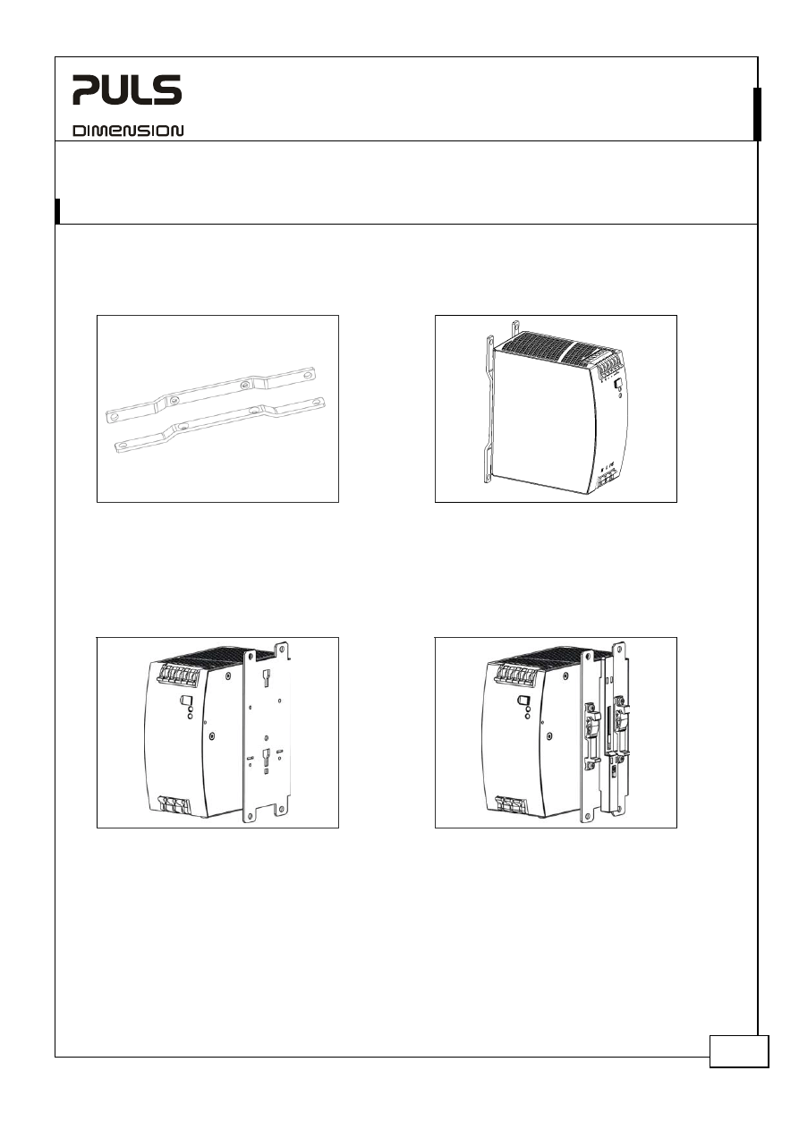
ZM1.WALL Wall mounting bracket
This bracket is used to mount Dimension units onto a flat surface without utilizing a DIN-Rail. The two aluminum
brackets and the black plastic slider of the unit have to be detached, so that the two steel brackets can be mounted.
Fig. 21-1 ZM1.WALL Wall Mounting Bracket
Fig. 21-2 Assembled Wall Mounting Bracket
ZM11.SIDE Side mounting bracket
This bracket is used to mount Dimension units sideways with or without utilizing a DIN-Rail. The two aluminum
brackets and the black plastic slider of the unit have to be detached, so that the steel brackets can be mounted.
For sideways DIN-rail mounting, the removed aluminum brackets and the black plastic slider need to be mounted on
the steel bracket.
Fig. 21-3 ZM11.SIDE Side Mounting Bracket
(Picture shows a mounted QS10 power supply)
Fig. 21-4 Side Mounting with DIN-rail brackets
(Picture shows a mounted QS10 power supply)
YR2.DIODE
Y-Series
10-60V, 20A, D
UAL
D
ECOUPLING
M
ODULE
Nov 2006 / Rev. 1.0 DS-YR2.DIODE-EN
All parameters are specified at 24V, 20A output current, 25°C ambient and after a 5 minutes run-in time unless otherwise noted.
www.pulspower.com Phone +49 89 9278 0 Germany
12/16
22. A
PPLICATION
N
OTES
22.1. R
ECOMMENDATIONS FOR
R
EDUNDANCY
Recommendations for the configuration of redundant power systems:
•
Use separate input fuse for each power supply.
•
It is desirable to set the output voltages of all power supplies to the same value to avoid a false signal of the
DC-ok signal.
•
Use Three-phase power supplies to gain functional safety if one phase fails.
•
When Single-phase power supplies are utilized connect them to different phases or mains circuits.
•
Use both inputs in parallel for currents above 10A.
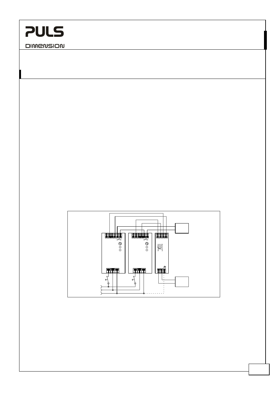
22.2. 1+1 R
EDUNDANCY UP TO
10A
1+1 Redundancy up to 10A requires two 10A power supplies and one YR2.DIODE decoupling module.
Fig. 22-1 Wiring diagram, 1+1 Redundancy, 10A output current
YR2.Diode
Decoupling
Module
+
-
OUT
+
-
IN 1
+
-
IN 2
L N PE
+ +
- -
QS10.241
Power
Supply
Adj
Overload
DCok
24V/10A
L N PE
+ +
- -
QS10.241
Power
Supply
Adj
Overload
DCok
24V/10A
Failure
Monitor
10A
Load
optional
I
I
L
N
PE
YR2.DIODE
Y-Series
10-60V, 20A, D
UAL
D
ECOUPLING
M
ODULE
Nov 2006 / Rev. 1.0 DS-YR2.DIODE-EN
All parameters are specified at 24V, 20A output current, 25°C ambient and after a 5 minutes run-in time unless otherwise noted.
www.pulspower.com Phone +49 89 9278 0 Germany
13/16
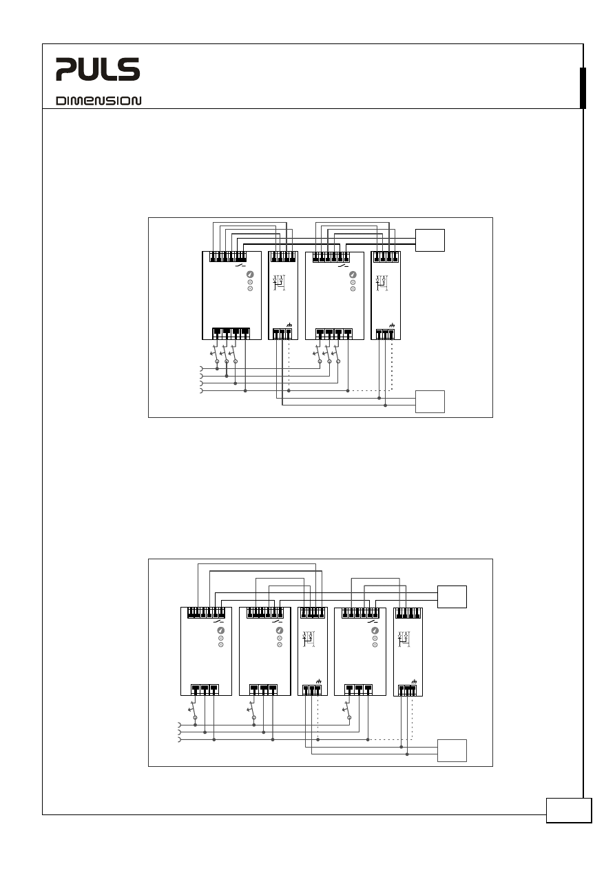
22.3. 1+1 R
EDUNDANCY UP TO
20A
1+1 Redundancy up to 20A requires two 20A power supplies and two YR2.DIODE decoupling modules.
Fig. 22-2 Wiring diagram, 1+1 Redundancy, 20A output current
L1 L2 L3 PE
+ +
- -
QT20.241
Power
Supply
Adj
Overload
DCok
24V/20A
YR2.Diode
Decoupling
Module
+
-
OUT
+
-
IN 1
+
-
IN 2
L1 L2 L3 PE
+ +
- -
QT20.241
Power
Supply
Adj
Overload
DCok
24V/20A
YR2.Diode
Decoupling
Module
+
-
OUT
+
-
IN 1
+
-
IN 2
Failure
Monitor
20A
Load
I
I
I
optional
opt
ional
I
I
I
L1
L2
PE
L3
22.4. N+1 R
EDUNDANCY
, E
XAMPLE WITH
20A
N+1 Redundancy with 20A requires three 10A power supplies and two YR2.DIODE decoupling modules.
Please note:
The DC-ok signal on the DIMENSION Q-Series will only work properly if the adjusted output voltage of each power
supply will be reached after turning-on the input power. A power supply operating in current limiting mode will result
in a DC-fail condition. Read notes in the individual power supply datasheets.
Fig. 22-3 Wiring diagram, N+1 Redundancy, example with 20A load current
YR2.Diode
Decoupling
Module
+
-
OUT
+
-
IN 1
+
-
IN 2
L N PE
+ +
- -
QS10.241
Power
Supply
Adj
Overload
DCok
24V/10A
L N PE
+ +
- -
QS10.241
Power
Supply
Adj
Overload
DCok
24V/10A
Failure
Monitor
20A
Load
optional
I
I
L
N
PE
YR2.Diode
Decoupling
Module
+
-
OUT
+
-
IN 1
+
-
IN 2
L N PE
+ +
- -
QS10.241
Power
Supply
Adj
Overload
DCok
24V/10A
I
YR2.DIODE
Y-Series
10-60V, 20A, D
UAL
D
ECOUPLING
M
ODULE
Nov 2006 / Rev. 1.0 DS-YR2.DIODE-EN
All parameters are specified at 24V, 20A output current, 25°C ambient and after a 5 minutes run-in time unless otherwise noted.
www.pulspower.com Phone +49 89 9278 0 Germany
14/16
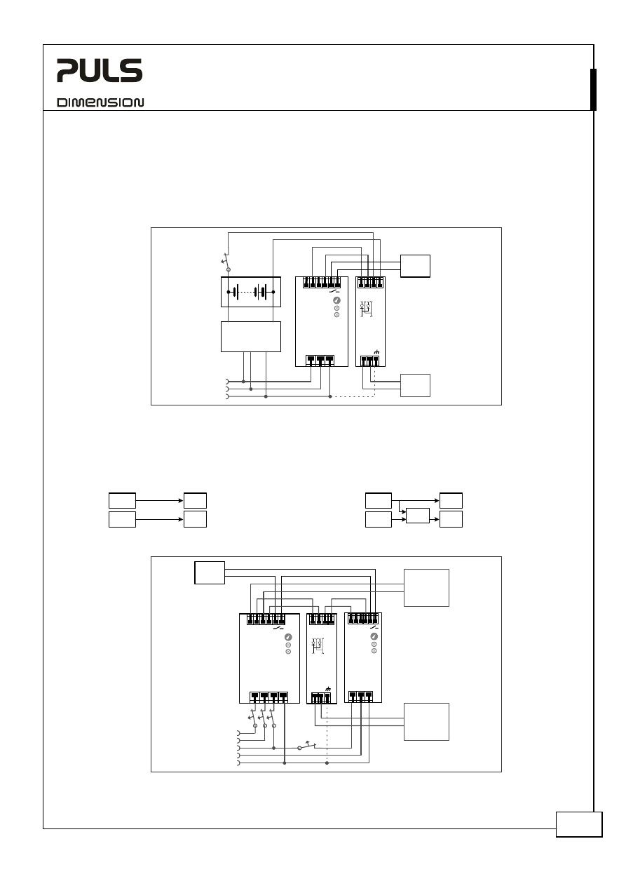
22.5. B
ATTERY
B
ACK
-
UP
A battery back-up with 10A requires one 10A power supply and one YR2.DIODE decoupling module.
Please note:
Set output voltage of power supply to 26.5Vdc minimum to avoid that the charger current flows to the load instead of
charging the battery. Use a fuse between battery and YR2.DIODE!
Fig. 22-4 Wiring diagram, 10A Battery back-up
YR2.Diode
Decoupling
Module
+
-
OUT
+
-
IN 1
+
-
IN 2
L N PE
+ +
- -
QS10.241
Power
Supply
Adj
Overload
DCok
24V/10A
Failure
Monitor
10A
Load
optional
L
N
PE
24V Battery
I
Battery
Charger
+
-
22.6. R
EDUNDANCY FOR
S
ENSITIVE
L
OADS
Cost effective solution to get redundant power for a PLC or controller system.
Standard
design:
Load
PS1
PLC
PS2
Improved
approach:
Load
PLC
PS1
PS2
YR2
Fig. 22-5 Wiring diagram,
Redundancy for Sensitive Loads
Failure
Monitor
Sensitive
Load
e.g.
Controller
opt
ional
L1 L2 L3 PE
+ +
- -
QT20.241
Power
Supply
Adj
Overload
DCok
24V/20A
L N PE
+ +
- -
QS5.241
Power
Supply
Adj
Overload
DCok
24V
5A
YR2.Diode
Decoupling
Module
+
-
OUT
+
-
IN 1
+
-
IN 2
I
I
I
L1
L2
PE
L3
I
N
Heavy
Loads
e.g. Motors
YR2.DIODE
Y-Series
10-60V, 20A, D
UAL
D
ECOUPLING
M
ODULE
Nov 2006 / Rev. 1.0 DS-YR2.DIODE-EN
All parameters are specified at 24V, 20A output current, 25°C ambient and after a 5 minutes run-in time unless otherwise noted.
www.pulspower.com Phone +49 89 9278 0 Germany
15/16
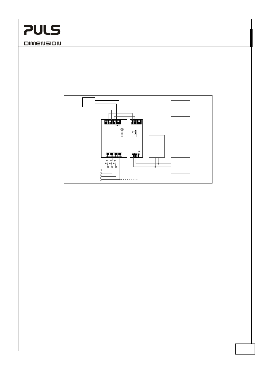
22.7. D
ECOUPLING OF
B
UFFERED
B
RANCHES
Buffer energy supplied from a DC-UPS or buffer module is not wasted in “power branches”.
Please note:
Set output voltage of the power supply to a level that the buffer unit or DC-UPS will not start unexpected. Take the
voltage drop of the YR2.DIODE into account.
Fig. 22-6 Wiring diagram, Decoupling of Buffered Branches
Failure
Monitor
Buffered
Load
e.g.
Controller
opt
ional
L1 L2 L3 PE
+ +
- -
QT20.241
Power
Supply
Adj
Overload
DCok
24V/20A
YR2.Diode
Decoupling
Module
+
-
OUT
+
-
IN 1
+
-
IN 2
I
I
I
L1
L2
PE
L3
Load
e.g. Motor
Buffer
Module
+
-
22.8. U
SE IN A
T
IGHTLY
S
EALED
E
NCLOSURE
When the decoupling module is installed in a tightly sealed enclosure, the temperature inside the enclosure will be
higher than outside. The inside temperature defines the ambient temperature for the decoupling module.
Results from such an installation:
Power supply is placed in the middle of the box, no other heat producer inside the box
Enclosure:
Rittal Typ IP66 Box PK 9516 100, plastic, 110x180x165mm
Load:
24V, 16A; (=80%) load is placed outside the box
Input:
24Vdc
Temperature inside enclosure:
57.8°C (in the middle of the right side of the power supply with a distance of 2cm)
Temperature outside enclosure: 24.6°C
Temperature rise:
33.2K
YR2.DIODE
Y-Series
10-60V, 20A, D
UAL
D
ECOUPLING
M
ODULE
Nov 2006 / Rev. 1.0 DS-YR2.DIODE-EN
All parameters are specified at 24V, 20A output current, 25°C ambient and after a 5 minutes run-in time unless otherwise noted.
www.pulspower.com Phone +49 89 9278 0 Germany
16/16
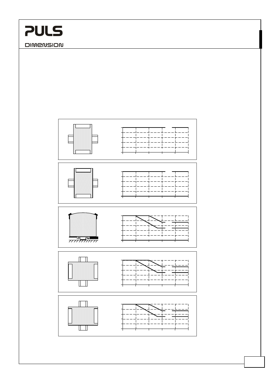
22.9. M
OUNTING
O
RIENTATIONS
Mounting orientations other than vertical require a reduction in continuous output current or a limitation in the
max. allowed ambient temperature. The amount of reduction influences the lifetime expectancy of the power supply.
Therefore, two different derating curves for continuous operation can be found below:
Curve A1
Recommended output current.
Curve A2
Max allowed output current (results approx. in half the lifetime expectancy of A1).
Fig. 22-7
Mounting
Orientation A
Standard
Orientation
Decoupling
Module
INPUT
OUTPUT
Output Current
0
10
20
30
40
60°C
4
12
16
20A
50
A1
8
Ambient Temperature
Fig. 22-8
Mounting
Orientation B
(Upside down)
De
couplin
g
Module
INPU
T
OUTP
UT
Output Current
0
10
20
30
40
60°C
4
12
16
20A
50
A1
8
Ambient Temperature
Fig. 22-9
Mounting
Orientation C
(Table-top
mounting)
Output Current
0
10
20
30
40
60°C
4
12
16
20A
50
8
A1
A2
Ambient Temperature
Fig. 22-10
Mounting
Orientation D
(Horizontal cw)
De
co
up
lin
g
Modul
e
INP
U
T
OUT
P
UT
Output Current
0
10
20
30
40
60°C
4
12
16
20A
50
8
A1
A2
Ambient Temperature
Fig. 22-11
Mounting
Orientation E
(Horizontal ccw)
De
co
up
lin
g
Modul
e
INP
U
T
OUT
P
UT
Output Current
0
10
20
30
40
60°C
4
12
16
20A
50
8
A1
A2
Ambient Temperature
Wyszukiwarka
Podobne podstrony:
Datasheet YRM2 DIODE
Datasheet SL4 100
Datasheet QS10 241 C1
pdf datasheet 5 id 352824 Nieznany
datasheet (2)
Citroen C4 Picasso Datasheet
datasheet
Datasheet SL5 300
LBB441850 DataSheet plPL E3338100491
Datasheet ML15 051
Datasheet SL10 305
Datasheet SL20 303
PLN 1P1000 DataSheet plPL E3242294027
Datasheet QT20 241 C1
Datasheet SLR2 100
więcej podobnych podstron