DS-350 G/GW Service Info SKYAZÚL RESOURCES
www.skyazul.com
Page 1
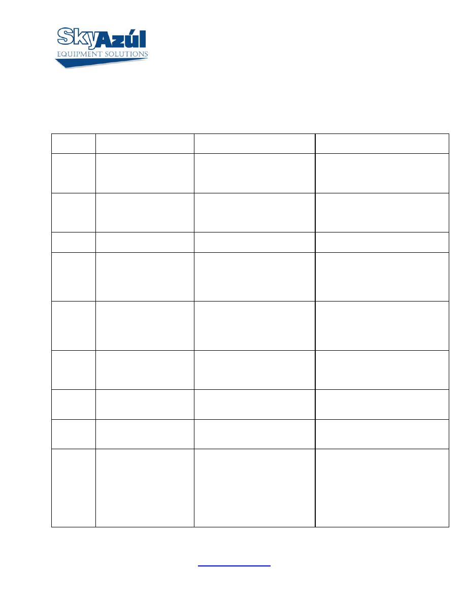
DS-350 G/GW ERROR CODE TABLE
ERROR
CODE
ERROR CAUSE
ACTION
E01
Minimum radius or
maximum angle range
exceeded
Fallen below the minimum
radius or above the angle given
in the load chart due to raising
the boom to far.
Lower boom back to a radius or
angle given in the load chart.
E02
Maximum radius or
minimum angle range
exceeded
The maximum radius or
minimum angle given in the load
chart was exceeded due to
lowering the boom too far.
Raise boom back to a radius or angle
given in the load chart.
E03
Prohibited slewing range
(no load area)
Slewing range prohibited with
load.
Slew back into admissible range.
E04
Operating mode not
available
Operating mode switch in the
console set incorrectly.
Operating mode is not
permissible with actual crane
configuration.
Set operating mode switch correctly
to the code assigned to the operating
mode of the crane.
E05
Length range not
permitted
Boom has been extended too far
or not far enough. Length sensor
adjustment changed; i.e. length
sensor cable slid off the cable
drum.
Retract or extend boom to correct
length given in the load chart.
E06
Fallen below angle range
with luffing jib operation.
Fallen below the minimum jib
angle specified n the respective
load chart due to luffing out the
jib too far.
Luff in the jib to a radius or angle
specified in the load chart.
E07 No
acknowledgment
signal from overload relay
(K1).
Overload relay is stuck, defective
or not being selected.
Replace relay.
E08 No
acknowledgment
signal from Anti-Two-
Block switch relay (K2).
Anti-Two-Block switch relay is
defective or not being selected.
Replace relay.
E11
Fallen below limit for the
measuring channel
“length”.
a.) Cable between length sensor
and central unit defective not
connected or water in the
connectors.
b.)Length sensor Potentiometer
defective.
c.)Electronic board in the
measuring channel defective.
a.)Check cable and connector as well
and replace, if necessary. Section 6.
b.)Replace and reset length sensor
Potentiometer. See Section 6.
c.)Replace main board and reset
pressure channels.
DS-350 G/GW Service Info SKYAZÚL RESOURCES
www.skyazul.com
Page 2
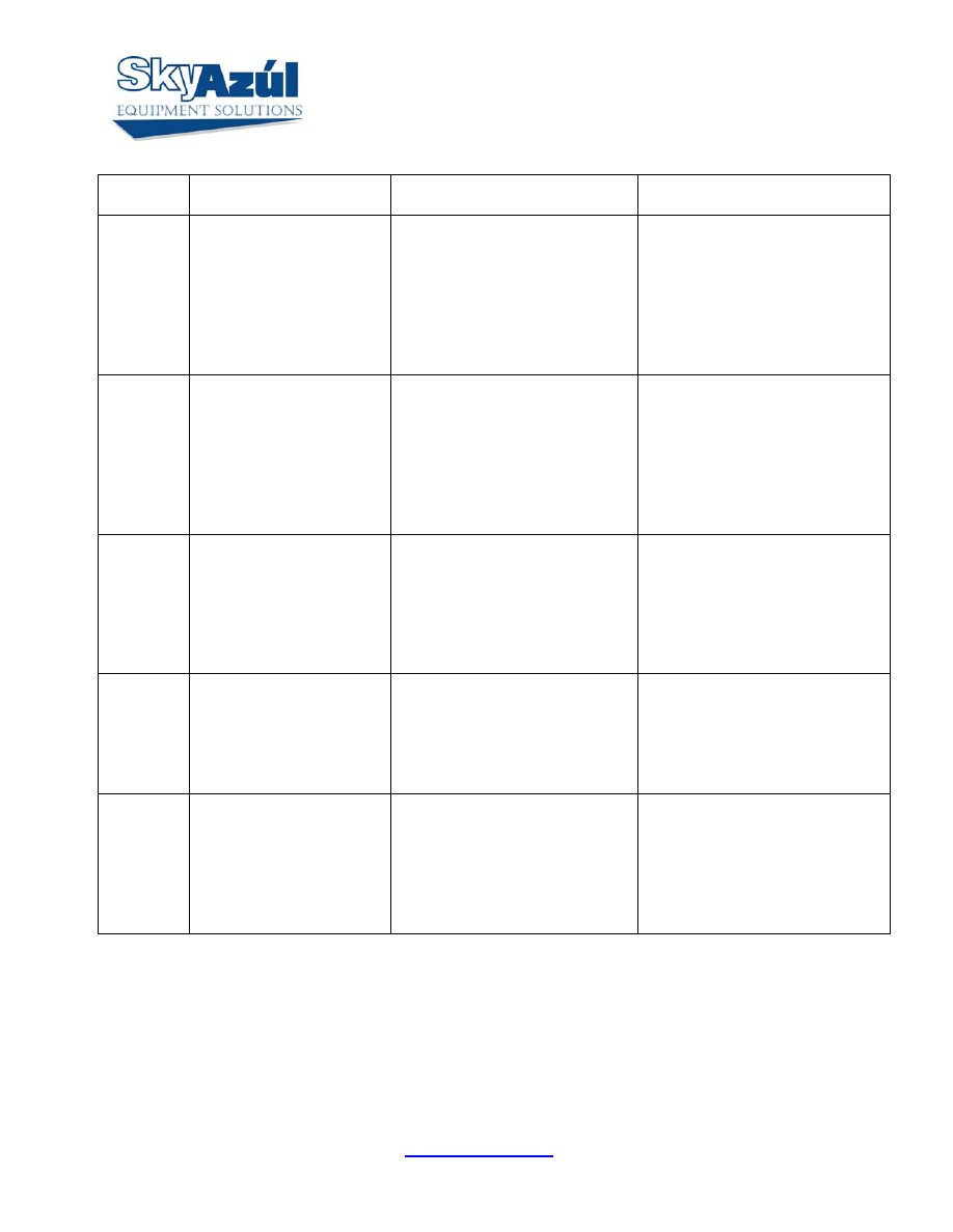
ERROR
CODE
ERROR CAUSE
ACTION
E12
Fallen below lower limit
value for the measuring
channel “pressure
transducer piston side”.
a.) Cable leading from the central
unit to the pressure transducer
defective, loose or water in the
connector.
b.)Pressure transducer on piston
side defective.
c.)Electronic component in the
measuring channel defective.
a.)Check cable and connector as
well and replace, if necessary.
b.)Replace pressure transducer
and reset pressure channel..
c.)Replace main board and reset
pressure channels.
E13
Fallen below lower limit
value for the measuring
channel “pressure
transducer rod side”.
a.)Cable leading from the central
unit to the pressure transducer
defective, loose or water in the
connector.
b.)Pressure transducer on rod
side defective.
c.)Electronic component in the
measuring channel defective.
a.)Check cable and connectors as
well and replace, if necessary.
b.)Replace pressure transducer
and reset pressure channel.
c.)Replace main board and reset
pressure channels..
E14
Fallen below lower limit
value for the measuring
channel “force”.
a.)Cable leading from the central
unit to the pressure transducer
defective, loose or water in the
connector. b.)Force transducer
defective. c.)Electronic
component in the measuring
channel defective.
a.)Check cable and connectors as
well and replace, if necessary.
b.)Replace force transducer.
c.)Replace main board and reset
pressure channels.
.
E15
Fallen below lower limit
value for the measuring
channel “angle main
boom”.
a.)Cable from central unit to the
length/angle sensor defective or
loose.
b.)Angle sensor defective.
c.)Electronic component in the
measuring channel defective.
a.)Check cable. Replace if
necessary. See Section 6
b.)Replace angle sensor and reset
adjustment.
c.)Replace main board and reset
pressure channels. .
E16
Fallen below lower limit
value for measuring
channel “Luffing Jib
Angle”.
a.)Cable from central unit to
angle sensor defective or
disconnected or water inside the
plug.
b.)Angle sensor defective.
c.)Electronic component in the
measuring channel defective.
a).Check cable as well as plug,
replace if need be.
b.)Replace angle sensor.
c.)Replace Main board and reset
pressure channels.
DS-350 G/GW Service Info SKYAZÚL RESOURCES
www.skyazul.com
Page 3
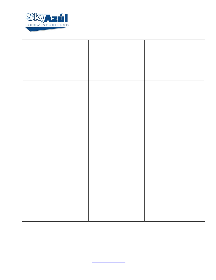
ERROR
CODE
ERROR CAUSE
ACTION
E17
Fallen below lower limit
value for the measuring
channel 7.
a.)Cable leading from the central
unit to the sensor of channel 7
defective, loose or water in the
connectors.
b.)Sensor of channel 7 defective.
c.)Electronic component in the
measuring channel 7 defective.
a.)Check cable as well as
connectors and replace, if
necessary.
b.)Replace sensor of channel 7 and
reset adjustment.
c.)Replace main board and reset
pressure channels.
E19
Error in the reference
voltage.
Electronic component on the
main board defective.
Replace main board and reset
pressure channels.
E20
No analog voltages
a.)The crane supply voltage is
too low.
b.)The voltage converter is
defective or short circuit in the
wiring.
a.)Check crane voltage.
b.)Check supply voltages.
E21
Upper limiting value for
the measuring channel
“length” exceeded.
a.)Cable from central unit to the
length/angle sensor defective or
loose.
b.)Length potentiometer
defective.
c.)Electronic component in the
measuring channel defective on
main board.
a.)Check cable. Replace if
necessary. See Section 6.
b.)Replace and reset length
potentiometer.
c.)Replace main board and reset
pressure channels.
E22
Upper limiting value for
the measuring channel
“pressure piston side”
exceeded.
a.)Cable from central unit to the
pressure transducer defective,
loose or water in the plug.
b.)Pressure transducer on piston
side defective.
c.)Electronic component in the
measuring channel defective on
main board.
a.)Check cable as well as plug.
Replace if necessary.
b.)Replace pressure transducer and
reset pressure channels.
c.)Replace main board and reset
pressure channels.
E23
Upper limit value for the
measuring channel
“pressure transducer rod
side” exceeded.
a.) Cable from the central unit to
press trans defective, not
connected or water in the
connectors.
b.) Pressure transducer on rod
side defective.
c.) Electronic component in the
measuring channel defective.
a.) Check cable and connectors as
well and replace, if necessary.
b.) Replace pressure transducer
c.) Replace main board and reset
pressure channels.
DS-350 G/GW Service Info SKYAZÚL RESOURCES
www.skyazul.com
Page 4
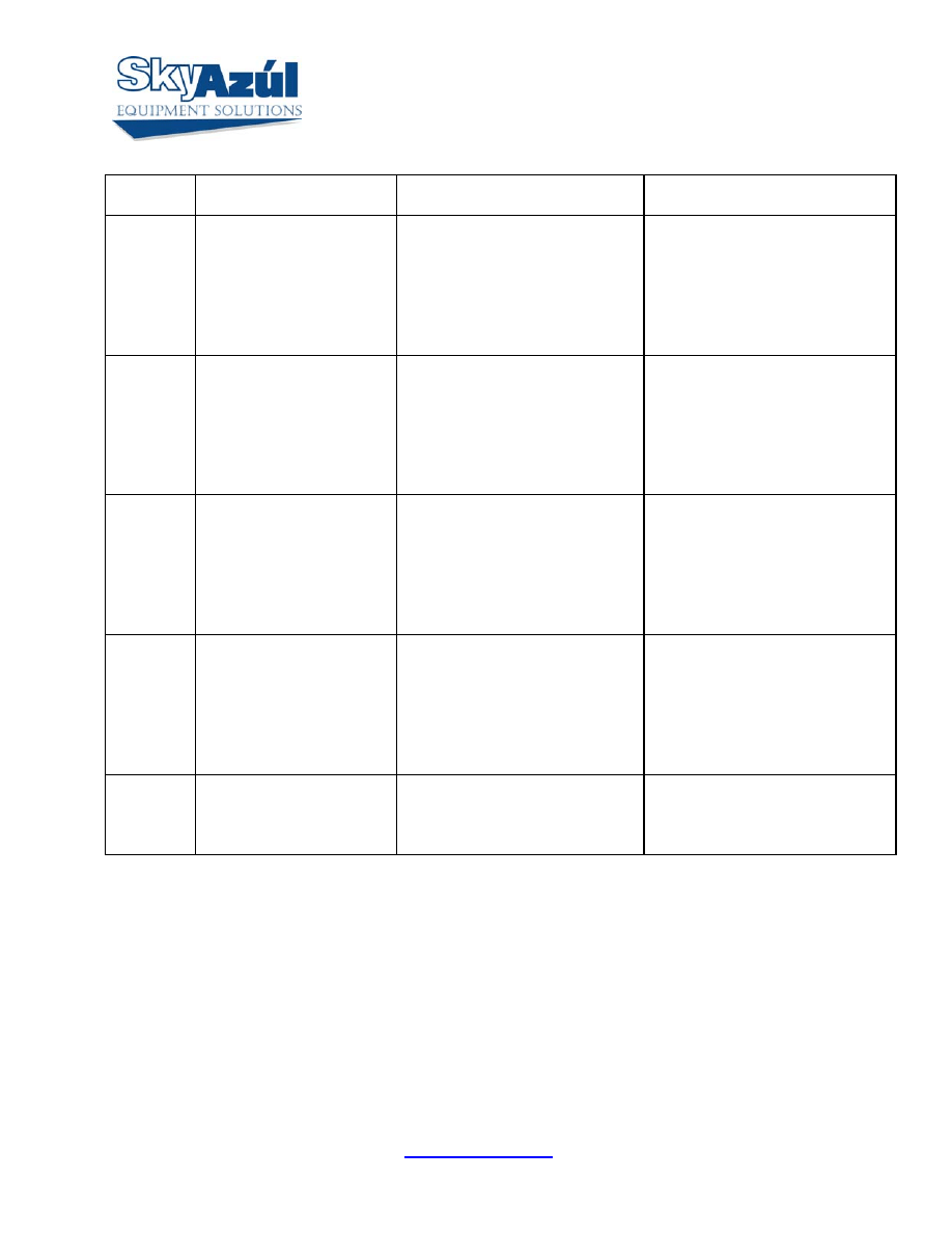
ERROR
CODE
ERROR CAUSE
ACTION
E24
Upper limit value for the
measuring channel “force”
exceeded.
a.) Cable leading from the central
unit to the force transducer
defective, not connected or water
in the connectors.
b.) Force transducer defective.
c.) Electric component in the
measuring channel defective.
a.) Check cable and connectors as
well and replace, if necessary.
b.) Replace force transducer.
c.) Replace main board and reset
pressure channels.
E25
Upper limit value for the
measuring channel “angle
main boom” exceeded.
a.) Cable leading from the
central unit to the length/angle
sensor defective, loose or water I
the connectors.
b.) Angle sensor defective
c.) Electronic component in the
measuring channel defective.
a.) Check cable as well as
connectors and replace, if
necessary. Section No. 6.
b.) Replace angle sensor and reset
adjustment.
c.) Replace main board and reset
pressure channels.
E26
Upper limit value for the
measuring channel
“Luffing Jib Angle”
exceeded.
a.) Cable leading from the central
unit to the jib angle sensor
defective, loose or water in the
connectors.
b.) Jib angle sensor defective. c.)
Electronic component in the
measuring channel defective.
a.) Check cable as well as
connectors and replace, if
necessary.
b.) Replace jib angle sensor and
reset adjustment.
c.) Replace main board and reset
pressure channels.
E27
Upper limit value for the
measuring channel 7
exceeded.
a.) Cable leading from the central
unit to the sensor of channel 7
defective, loose or water in the
connectors.
b.) Sensor of channel 7 defective.
c.) Electronic component in the
measuring channel 7 defective.
a.) Check cable as well as
connectors and replace, if
necessary.
b.) Replace sensor of channel 7
and reset adjustment.
c.) Replace main board and reset
pressure channels.
E29 Reference
voltage
defective.
a.) The total of the supply and
the reference voltages on MP10
is more than 3.3V
b.) A/D converter defective.
a.) Check supply voltages.
b.) Replace main board and reset
pressure channels.
DS-350 G/GW Service Info SKYAZÚL RESOURCES
www.skyazul.com
Page 5
ERROR
CODE
ERROR CAUSE
ACTION
E31
Error in the system
program.
a.) EPROM with system program
defective.
b.) Electronic component on the
main board defective.
a.) Replace system program
EPROM
b.) Replace main board and reset
pressure channels.
E37
Error in the program run
a.) EPROM with system program
defective.
b.) Electronic component on the
main board defective.
a.) Replace system program
EPROM.
b.) Replace main board and reset
pressure channels. .
E38
Wrong system program in
the LMI.
The system program in the LMI
does not correspond to the
programming in the data
EPROM
Replace system program EPROM
E 41
Error in the external
RAM.
Replace main board and reset
pressure channels. Section7
E 42
Error in the external
write/read memory
(RAM).
Internal defect in digital part of
CPU.
Exchange write/read memory
(CMOS-RAM). Replace main
board and reset pressure channels.
See Section 7.
E 45
Error in internal
communications.
Defective electronic component.
Replace main board and reset
pressure channels. Section 7.
E 48
Malfunction in the
monitored write/read
memory.
Internal defect in digital part of
CPU
Replace main board and reset
pressure channels.
E 51
Error in data memory.
Data EPROM on the main board
defective.
Replace Data EPROM. Make
sure BR3 on the main board is
installed.
E71 Incorrect
acknowledgment
of the 1. Relay on the
terminal board A101.
a.) Anti Two-block relay is stuck
or defective.
b.) Anti Two-Block relay is not
being selected due to a break on
the terminal board A101, main
board or ribbon cables.
a.) Replace 1. relay.
b.) Check terminal board A101,
main board and ribbon cables as
well as replace defective part, if
necessary.
E72 - E77 Analogous to E71 for the
relays 2...7.
Analogous to E71 for the relays
2...7.
Analogous to E71 for the relays
2..7.
DS-350 G/GW Service Info SKYAZÚL RESOURCES
www.skyazul.com
Page 6
ERROR
CODE
ERROR CAUSE
ACTION
E89
Change of the operating
code during lifting a load.
The operating mode switch in
the console was used during
lifting a load.
Lower the load and set the
operating mode switch correctly
to the code assigned to the actual
operating mode of the crane.
E 91
No data transmission from
console to central unit.
(See Section 8 and 9)
a.)This causes no display.
b.)Interruption or accidental
ground in the line from console
electronics to central unit.
c.)Transmitter/receiver module
defective.
a.)Check the connection between
console electronics and central
unit.
b.)If you find an accidental
ground, the transmitter module in
the console electronics can be
damaged. You should, therefore,
replace the console electronics.
Replace console electronics or
main board respectively.
E92
Error in the data
transmission from console
to central unit. (See also
Section 8 and 9)
a.) Temporary interruption of
the data line from console
electronics to central unit. b.)
Transmitter/receiver module
defective.
a.) Check the connection between
console electronics and central
unit.
E93
Error in the data
transmission from central
unit to console. (See also
Section 8 and 9)
a.) Temporary interruption of
the data line from console
electronics to central unit. b.)
Transmitter/receiver module
defective.
a.) Check the connection between
console electronics and central
unit.
b.) Replace console electronics or
main board respectively.
DS-350 G/GW Service Info SKYAZÚL RESOURCES
www.skyazul.com
Page 7
ERROR
CODE
ERROR CAUSE
ACTION
E94
No data transmission from
central unit to console.
a.) Interruption or accidental
ground in the line from console
electronics to central unit.
b.) Transmitter/receiver module
defective.
c.) Data-EPROM defective.
d.) CPU defective.
e.) Electromagnetic interference
(when switching contractors or
valves)
a.) Check the connection between
console electronics and central
unit. If you find an accidental
ground, the transmitter module in
the console electronics can be
damaged. Replace the console
electronics.
b.) Replace console electronics or
main board respectively. c.)Check
data EPROM.
d.) Replace main board.
e.) Eliminate interference source
by inverse diodes or varistors.
E95
Error in the crane data
EPROM
a.) Data EPROM defective b.)
Position of jumper for the
selection of the type of EPROM
is wrong
c.) Electronics component on
the main board defective.
a.) Replace data EPROM b.)
Check the jumper position c.)
Replace main board and reset
pressure channels.
E96
Error in the internal RAM
of the CPU of the console
CPU or main board of the
console defective
Replace console main board &
Appendix A.
E97
Error in the external RAM
of the CPU of the console
a.) External RAM of the
console defective
b.) Electronic component on the
main board defective.
a.) Replace console main board b.)
Replace console main board
E98
Wrong jumper position in
the console
a.) The jumper position BR
9/BR 10 in the console does not
correspond to the actual type of
central unit.
b.) Electronic component on the
main board defective.
a.) Check the jumper position b.)
Replace console main board.
DS-350 G/GW Service Info SKYAZÚL RESOURCES
www.skyazul.com
Page 8
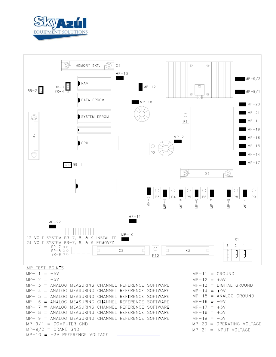
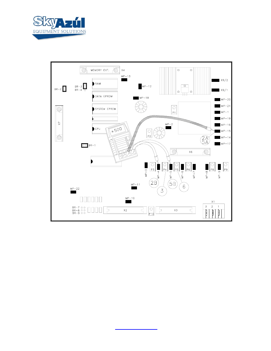
BASIC ADJUSTMENT AND VOLTAGE CHECKS
DS-350 G/GW Service Info SKYAZÚL RESOURCES
www.skyazul.com
Page 9
Main Board - Piston & Rod Pressure Channel Zero Point Adjustment
1. LOWER BOOM ALL THE WAY DOWN (NO REST PRESSURE) THEN DISCONNECT HYDRAULIC
HOSE FROM THE PISTON SIDE PRESSURE TRANSDUCER.
2. CONNECT A DIGITAL VOLTMETER TO MAIN P.C. BOARD
A) BLACK (-) LEAD TO MP15
B) RED (+) LEAD TO MP4
3. ADJUST P4 TO OBTAIN A READING OF 0.500 VOLTS (500MV) ON METER.
4. DISCONNECT HYDRAULIC HOSE FROM THE ROD SIDE PRESSURE TRANSDUCER.
5. CONNECT A DIGITAL VOLTMETER TO MAIN P.C. BOARD
A) BLACK (-) LEAD TO MP15
B) RED (+) LEAD TO MP5
6. ADJUST P5 TO OBTAIN A READING OF 0.500 VOLTS (500MV) ON METER.
7. RECONNECT HYDRAULIC HOSES TO PRESSURE TRANSDUCERS, THEN BLEED THE AIR FROM
HYDRAULIC LINES.
Wyszukiwarka
Podobne podstrony:
PAT DS 350 Graphic Modular GM Service Data
PAT DS 350 Graphic Modular GM Service Data
PAT DS 160 Service Data
ENGINE MECHANICAL Service data
ENG DS 1 1414305 0 DATA SHEET 1
Prezentacja firmy MARSTATE SERVICE BHP PPOZ PPT
PaT eczki G( ), niefermentujT ce
Gatunki dziennikarskie licencjat PAT czesc 2
GW CW12Bv02
GW CW15 Dla chetnych
GW PROJEKT D
CW2006EX Mill Turn data sheet web
GW Praca semestralna zasady i wytyczne
hplj 5p 6p service manual vhnlwmi5rxab6ao6bivsrdhllvztpnnomgxi2ma vhnlwmi5rxab6ao6bivsrdhllvztpnnomg
3 Data Plotting Using Tables to Post Process Results
An%20Analysis%20of%20the%20Data%20Obtained%20from%20Ventilat
więcej podobnych podstron