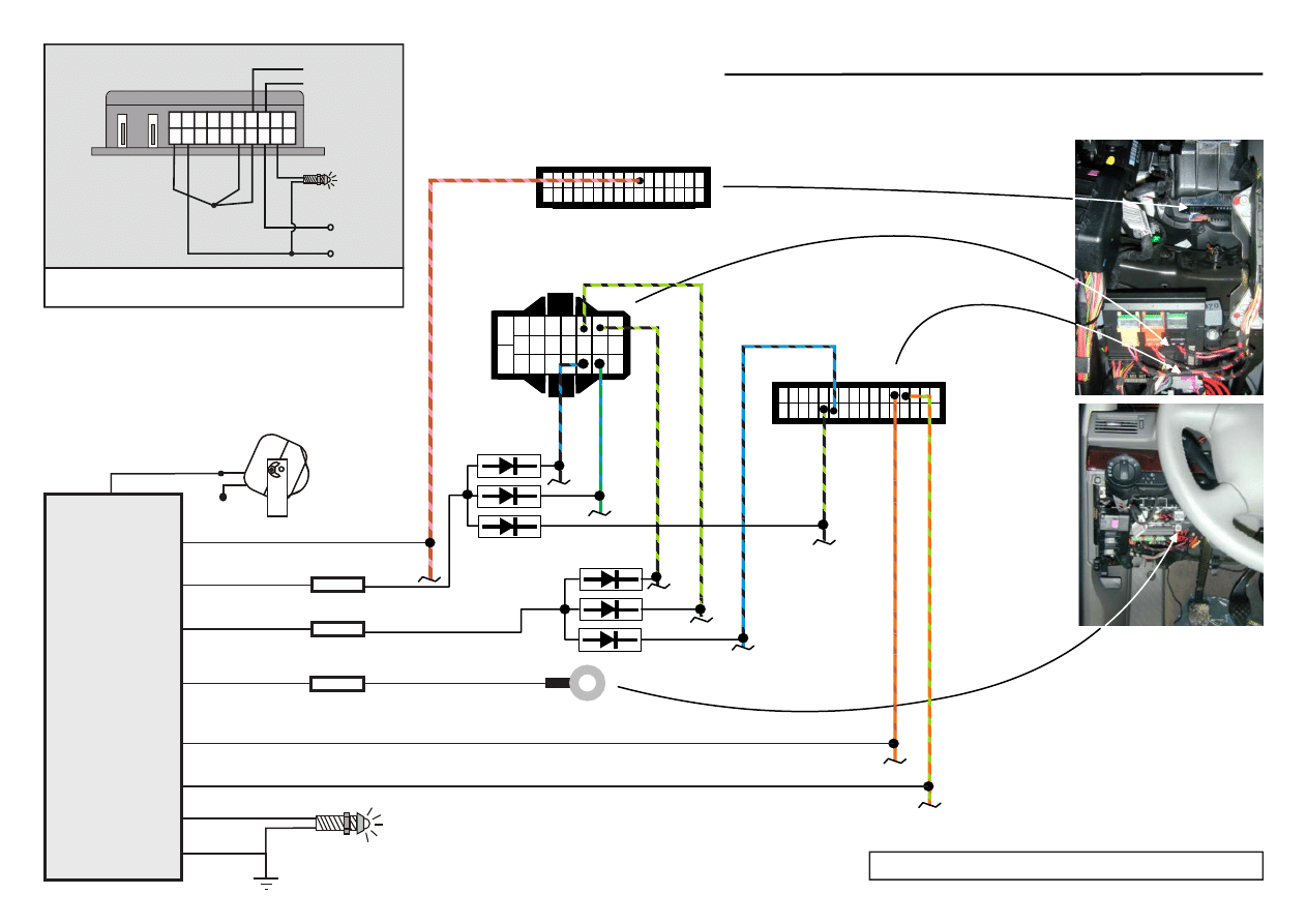
RED pin 20
+12V
GRN/WHT pin 22
GRN/YEL pin 12
+12V (2A)
LED
Hood sensor
WHT/BLK pin16
ORG pin11
RED/BLK pin 21
BLK pin14
ORG/GRN pin 10
ORG/BRN pin 9
CAN-L
CAN-H
22
23
19 16 13 10
7
4
1
20 17 14 11
8
5
2
21 18 15 12
9
6
3
FUSE
FUSE
FUSE
1
16
17
32
B
R
N
/P
N
K
B
L
K
/B
L
U
G
R
N
/B
L
U
B
L
K
/G
R
N
G
R
N
/B
L
K
B
L
U
/B
L
K
B
L
K
/G
R
N
O
R
G
/B
R
N
O
R
G
/G
R
N
1
17
16
32
Turn Indicator
Turn Indicator
GROUND
Make: Audi Model: A4 Year: 2001-2005
rev. 27.05.2007
GND (MASS)
RE / L
D B K
+12V
Diode LED
MAIN POWER
Y
E
L
B
L
K
3 4 5 6 7 8 9 10 11 12
13 14 15 16 17 18 19 20 21 22
W
H
T
G
R
Y
R
E
D
CAN-BUS
ORG/GRN CAN H
ORG/BRN CAN L
Connection of
wires for the
purpose of
automatic
finding all codes
in the car
1
2
The function No. 7 must be switched off (default setting)!
SIREN
CAUTION! This installation diagram must only be used as a guideline for the installation.
Equipment delivered with the car varies from model to model and from market to market.
Document Outline
Wyszukiwarka
Podobne podstrony:
Audi TB 01 03 05 Readiness Quick Reference
36 SC DS300 R AUDI A4 B 98 01
Audi TB 01 03 05 Readiness Quick Reference
Audi A4 2001 CAN
Audi A4 CAN bus wires 2002
Audi A4 Bosch crypted9 01 eng
Audi TB 01 03 05 Readiness Quick Reference
Wykład Mechatronika 01 05
01 05 POŚ Wytyczne dla sporzadzania
Modlitwa Wiernych 01.05.2010, Szkoła Liturgii, Modlitwy wiernych
AUDI A4 8E 2005pl
audi A4 6 stala praca wentylatora chlodnicy
00 01 05 Kolo zebate stozkowe male 1
Audi A4 nieszczelny parownik
[Audi A4 8E ] Zestaw naprawczy do luzujacej sie rolety w Avancie B6 i B7
kodowanie sterownikow Audi A4, auta, Diagnostyka dokumety, procedury diagnostyczne
więcej podobnych podstron