185
In This Chapter
10
Creating Placed Features
This tutorial introduces you to placed features, and
builds on what you learned in previous tutorials. A
placed feature is a well-defined common shape, such as
a hole or a fillet. To create a placed feature, you only
need to supply its dimensions. Autodesk
®
Mechanical
Desktop
®
creates the feature for you.
In this lesson, you learn how to create and modify
placed features.
■
Holes
■
Face drafts
■
Fillets
■
Chamfers
■
Shells
■
Surface cuts
■
Patterns
■
Copied features
■
Combined features
■
Part splits

186
|
Chapter 10
Creating Placed Features
Key Terms
Term
Definition
chamfer
A beveled surface between two faces.
combine feature
A parametric feature resulting from the union, subtraction, or intersection of a
base part with a toolbody part.
draft angle
An angle applied parallel to the path of extruded, revolved, or swept surfaces or
parts. A draft angle is used to allow easy withdrawal from a mold or easy insertion
into a mated part.
face draft
A part face that has a draft angle applied to it. Used to create an angle on a face
that will be needed when pulling a part out of a mold.
fillet
A curved transition from one part face or surface to another. The transition cuts
off the outside edge or fills in the inside edge. The fillet can have a constant or
variable radius.
hole
A geometric feature with a predefined shape: drilled, counterbore, or countersink.
pattern feature
A parameter-driven collection of duplicate features. You can create rectangular,
polar, and axial patterns. If you change the original patterned feature, all the
elements in the pattern change.
placed feature
A well-defined mechanical shape that does not require sketches, such as a hole,
chamfer, or fillet. Placed features are constrained to the feature on which they are
placed, and they are geometrically dependent.
shell
A Mechanical Desktop feature that cuts portions of the active part by offsetting its
faces.
surface cut
A feature on a part created when a surface is joined to the solid. Where the
surface cuts the part or protrudes, the part face assumes the curved shape of the
surface. The surface, like other features, is parametric; both the surface and the
part retain their parametric relationship whenever either is modified.
Basic Concepts of Placed Features
|
187
Basic Concepts of Placed Features
Placed features are well defined features that you don’t need to sketch, such
as fillets, holes, chamfers, face drafts, shells, surface cuts, patterns, combined
features, and part splits.
You specify values for their parameters and then you position them on your part.
To modify placed features, you simply change the parameters controlling them.
Open the file p_feat.dwg in the desktop\tutorial folder.
NOTE
Back up the tutorial drawing files so you still have the original files if you
make a mistake. See “Backing up Tutorial Drawing Files” on page 40.
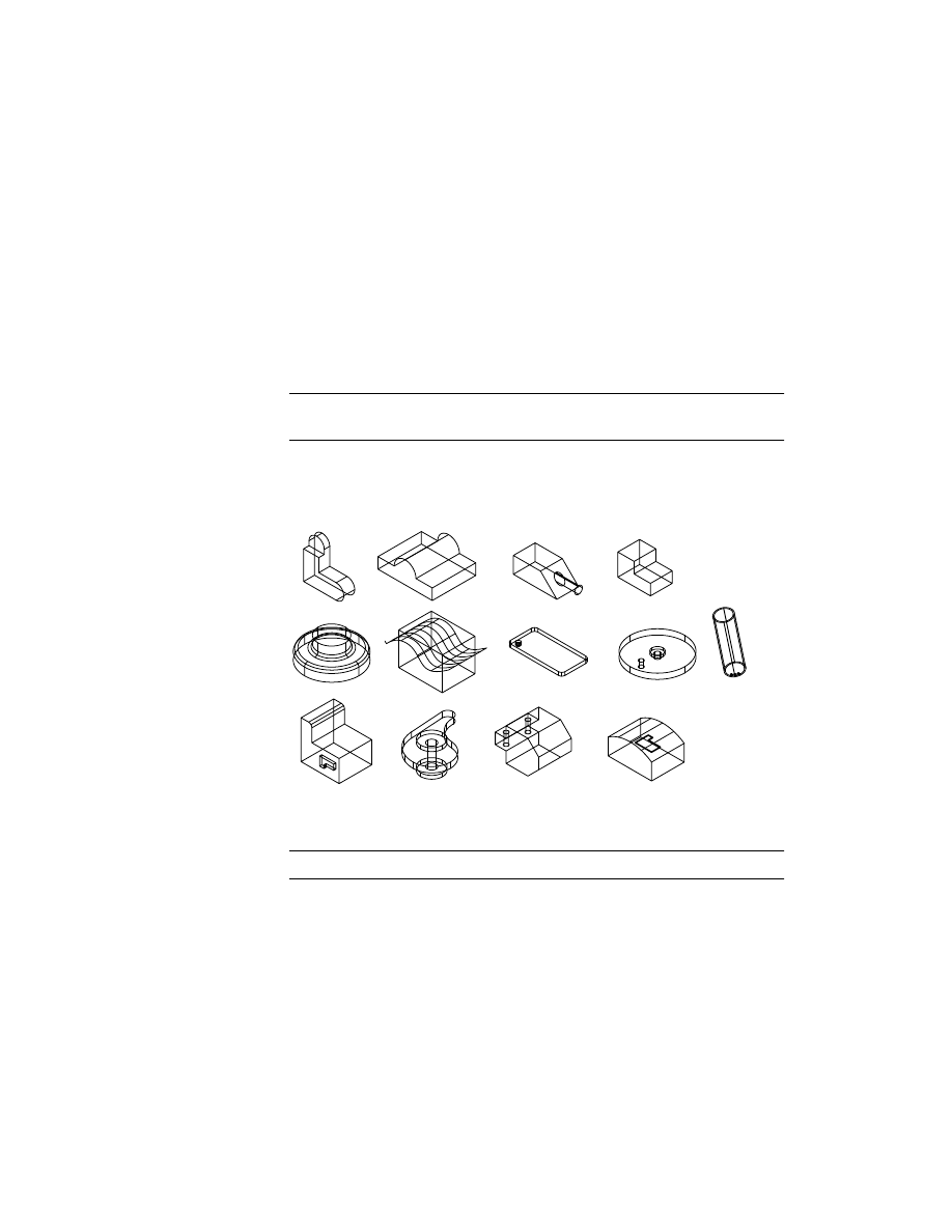
The drawing includes thirteen parts which contain the geometry you need to
create the features in this tutorial. If you are interested in how the parts in
this drawing were created, activate a part and use
AMREPLAY
.
Before you begin, expand the Browser hierarchy by clicking the plus sign in
front of
P_FEAT. Expand the hierarchy of the active part HOLE_1.
NOTE
For clarity, the work features are not shown.
188
|
Chapter 10
Creating Placed Features
Creating Hole Features
You can create drilled, counterbore, and countersink hole features. Each may
be assigned tapped hole information. Holes can extend through the part,
stop at a defined plane, or stop at a defined depth. You can change a hole
from one type to another at any time.
When you create a hole, you can use the Thread tab in the Hole dialog box
to include threads. Threads can also be added to existing holes.
Instead of creating a custom hole, you can specify a standard hole from an
external file. Standard holes can be tapped or untapped.
In this exercise, you create hole features first. Then you add thread data to
the hole you created.
To create a hole feature
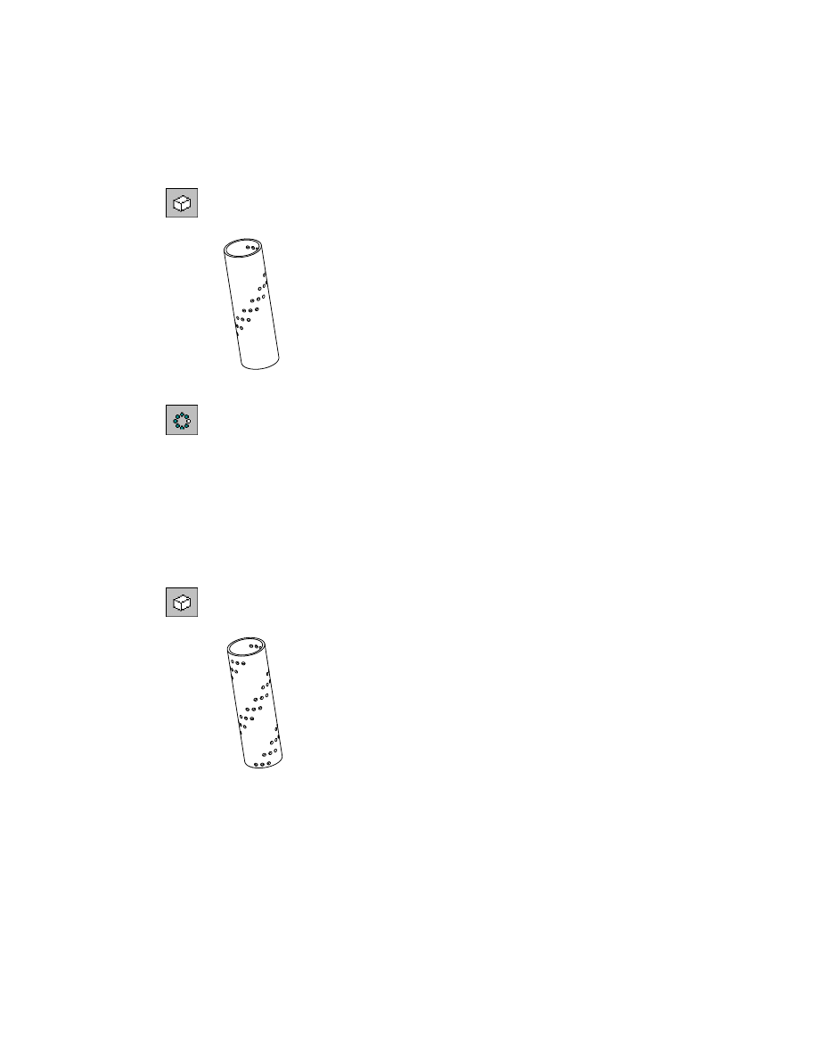
1
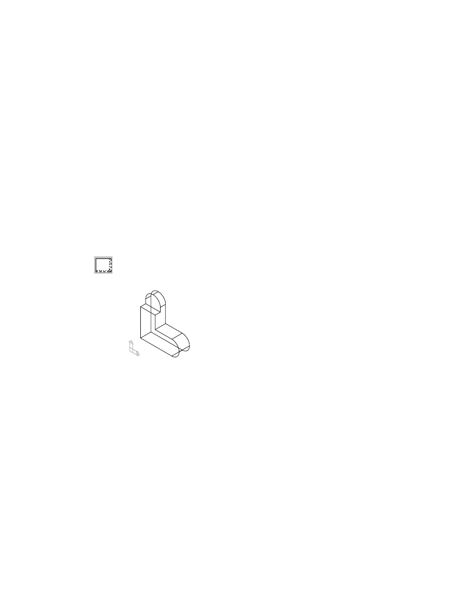
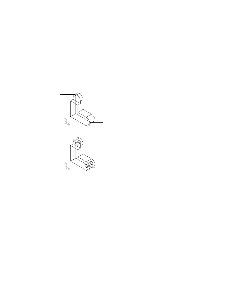
Activate HOLE_1 part, and zoom in to it.
Browser
In the Browser, double-click HOLE_1. Now right-click
HOLE_1 and choose Zoom to.
HOLE_1 is created from two extrusions.
Creating Hole Features
|
189
2
Use
AMHOLE
to create two drilled holes.
Context Menu
In the graphics area, right-click and choose Placed
Features ➤ Hole.
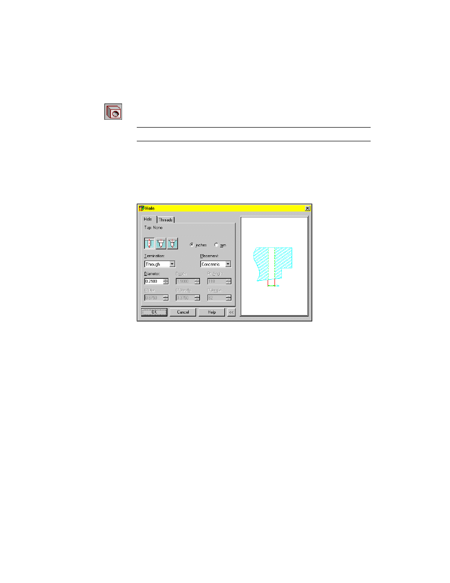
NOTE
Hold your cursor over an icon to see a tooltip that identifies the icon.
In the Hole dialog box, on the Hole tab, select the Drilled hole type icon, and
specify:
Termination:
Through
Placement:
Concentric
Diameter:
Enter .25
Choose OK to exit the dialog box.
190
|
Chapter 10
Creating Placed Features
3
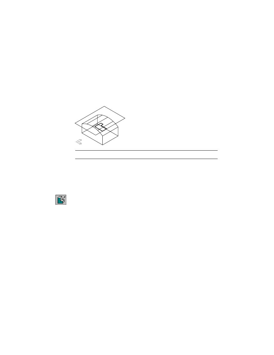
Define the locations for the holes, responding to the prompts.
Select work plane or planar face [worldXy/worldYz/worldZx/Ucs]:
Specify a face (1)
Select concentric edge:
Specify an edge (1)
Select work plane or planar face [worldXy/worldYz/worldZx/Ucs]:
Specify a face (2)
Select concentric edge:
Specify an edge (2)
Select work plane or planar face [worldXy/worldYz/worldZx/Ucs]:
Press
ENTER
Your drawing should look like this.
Next, add internal threads to the HOLE_1.
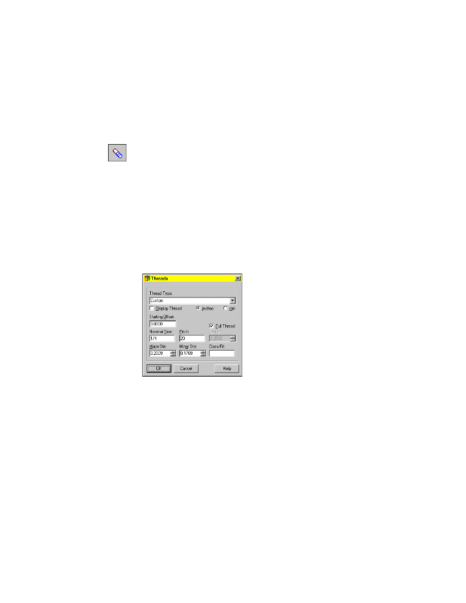
Creating Thread Features
You can create internal or external threads on cylindrical, conical, and ellip-
tical shapes. You edit existing threads from within the Thread dialog box. As
with holes, you can specify standard threads from an external file.
In the following exercise, you add an external thread to one of the cylindrical
holes you created.
1
2
Creating Thread Features
|
191
To create a thread feature
1
In the Browser, select the hole to add threads.
Browser
Select Hole1.
2
Define the thread for Hole1
Context Menu
In the graphics area, right-click and choose Placed
Features ➤ Thread
Respond to the prompts:
Select cylindrical/conical edge or face:
Select the circular edge of Hole1
Enter an option [Next/Accept] <Accept>:
Press
ENTER
In the Threads dialog box, specify:
Thread Type:
Custom
Full Thread:
Select the check box
Major Dia:
0.2009
Minor Dia:
0.1709
Choose OK.
The thread feature is placed on Hole1 and an icon representing the external
thread is added to the Browser hierarchy.
Next, you change one of the drilled holes to a counterbore hole, and change
the minor diameter of the thread feature.
192
|
Chapter 10
Creating Placed Features
Editing Hole Features
You can change a hole feature from one type of hole to another by modifying
the parameters defining the hole.
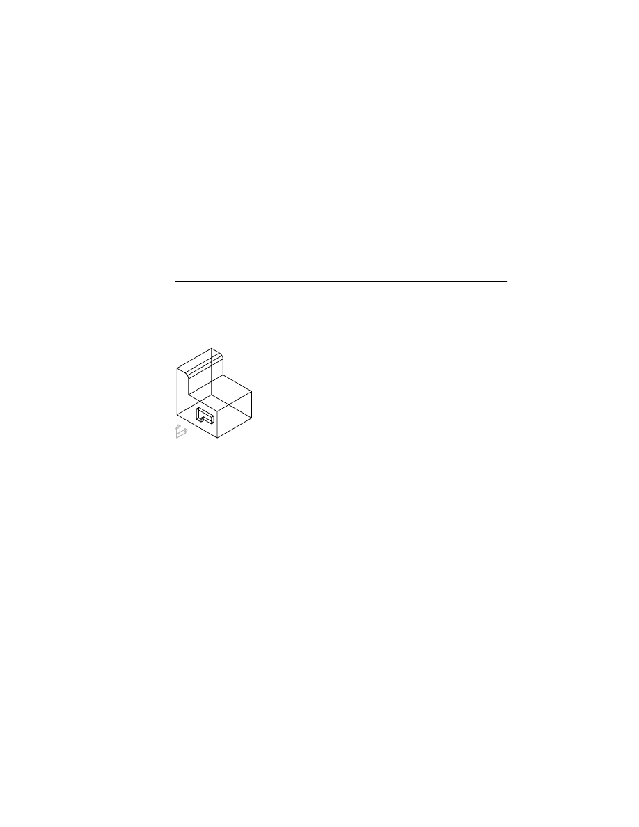
To edit a hole feature
1
Use
AMEDITFEAT
to change the second hole to a counterbore hole, respond-
ing to the prompts.
Context Menu
In the graphics area, right-click and choose Edit Features
➤ Edit.
Enter an option [Sketch/surfCut/Toolbody/select Feature] <select Feature>:
Specify Hole2
Enter an option [Next/Accept] <Accept>:
Press
ENTER
2
In the Hole dialog box, select the Counterbore icon, and specify:
Termination:
Through
Dia:
Enter .2
C’Dia:
Enter .375
C’Depth:
Enter .15
Choose OK to exit the dialog box.
3
Continue on the command line.
Select object:
Press
ENTER
4
Use
AMUPDATE
to update the part, responding to the prompt.
Context Menu
In the graphics area, right-click and choose Update Part.
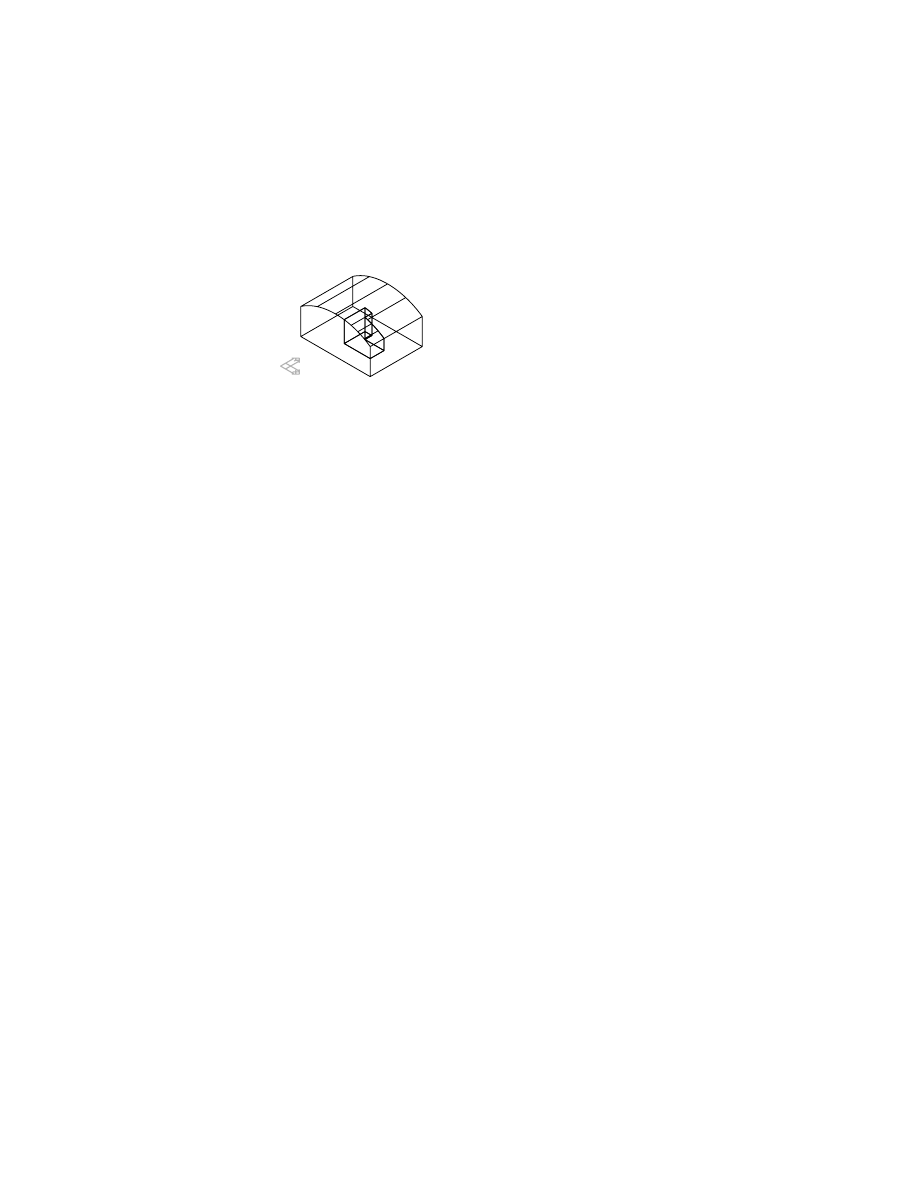
Your part should look like this.
Save your file.
Editing Thread Features
|
193
Editing Thread Features
You can redefine the size of an existing thread. If you need to change the
thread type, it is necessary to delete the existing thread and create a new one.
To edit a thread feature
1
Use
AMEDITFEAT
to change and display the thread feature, responding to the
prompts.
Context Menu
In the graphics area, right-click and choose Edit Features
➤ Edit.
Enter an option [Sketch/surfCut/Toolbody/select Feature] <select Feature>:
Press
ENTER
Select feature:
Select the ExternalThread1 feature
2
In the Threads dialog box, specify:
Thread Type:
Custom
Display Thread:
Select the check box.
Minor Diameter:
0.1805
Choose OK.
3
Continue on the command line.
Select object:
Press
ENTER
The thread feature is displayed, and reflects the new minor diameter value.
Next, you learn how to create and edit face drafts.
194
|
Chapter 10
Creating Placed Features
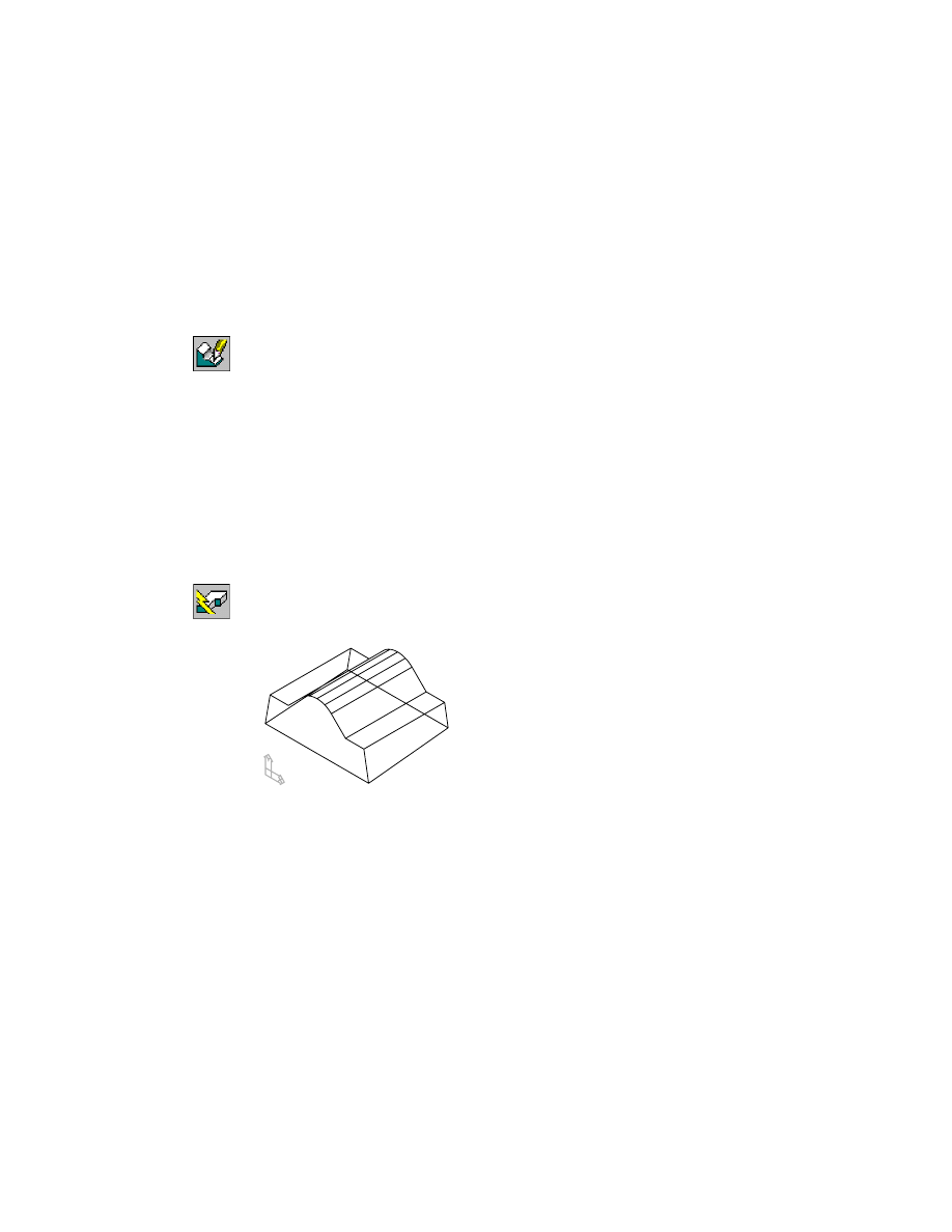
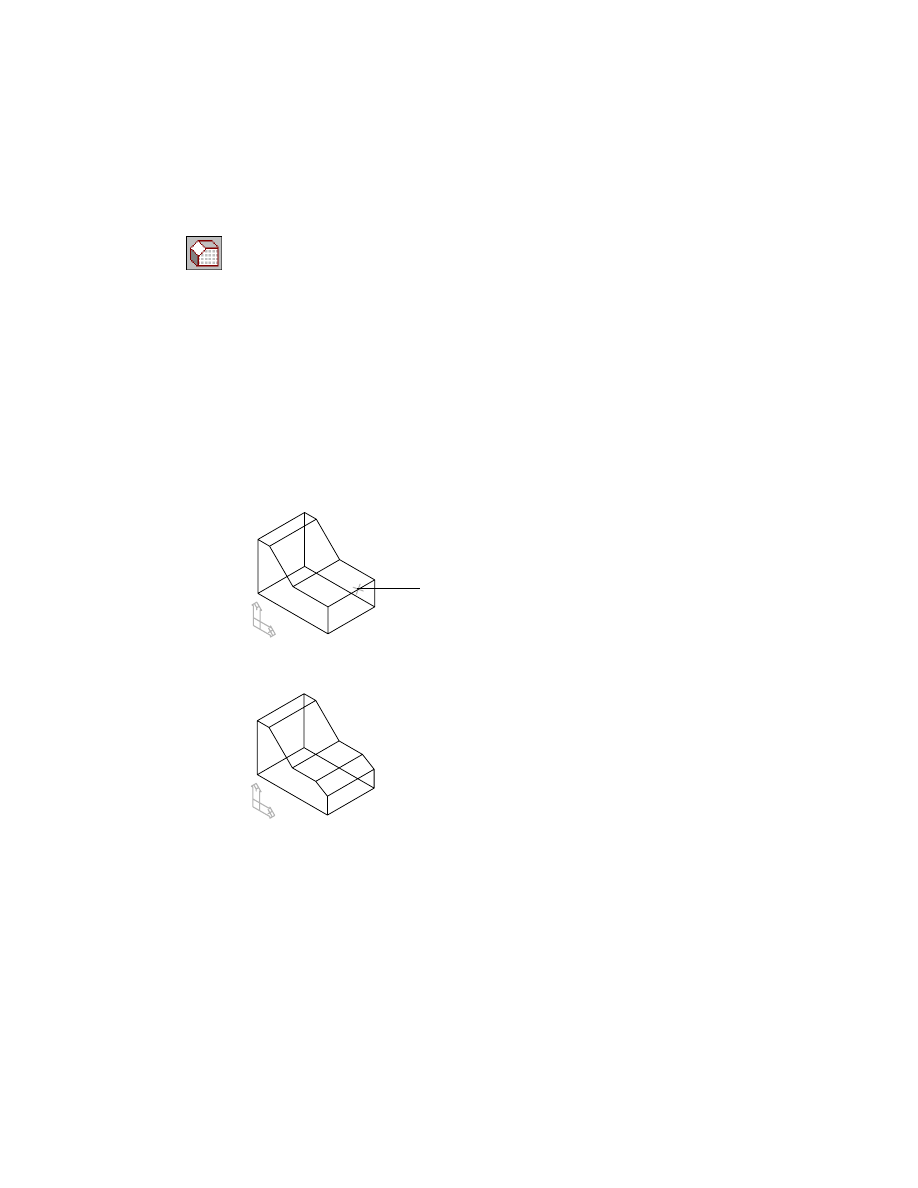
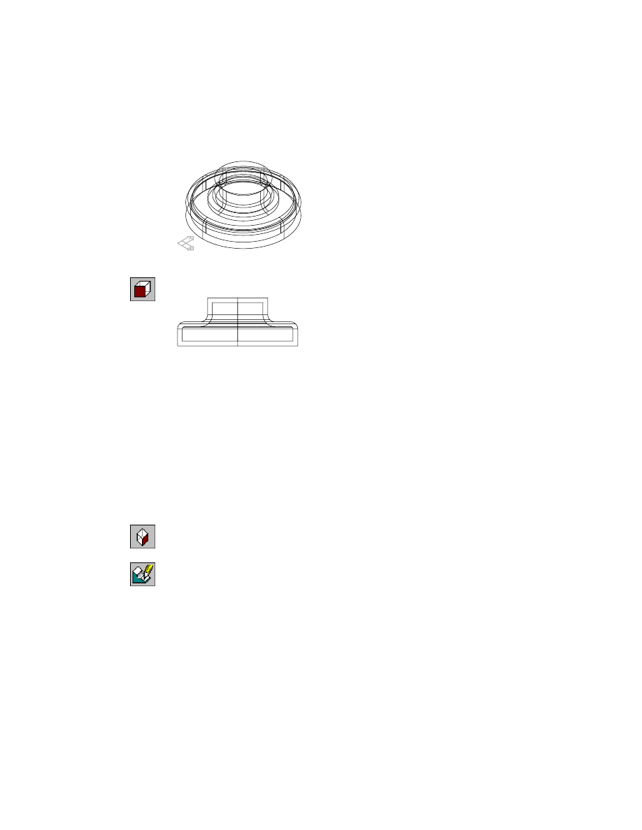
Creating Face Drafts
Face drafts are used to add a small angle to one or more faces of a part; then
the part can be easily extracted from a mold after it is manufactured.
Face drafts can be applied from a specified plane, an existing part face, or a
part edge. You can also create a shadow draft from a circular face. If you are
creating a face draft from a plane, the plane can be either an existing face, or
a work plane offset from the part.
First, activate F-DRAFT_1 and zoom in on the part. Turn off the visibility of
HOLE_1.
The part contains a simple extrusion.
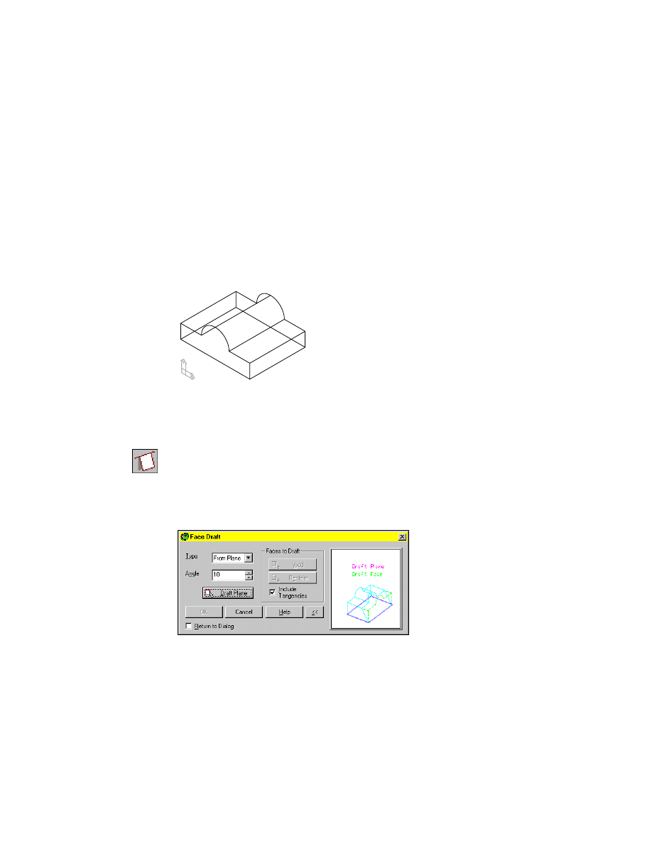
To create a face draft from a plane
1
Use
AMFACEDRAFT
to create a face draft.
Context Menu
In the graphics area, right-click and choose Placed
Features ➤ Face Draft.
In the Face Draft dialog box, specify:
Type:
From Plane
Angle:
Enter 10
Creating Face Drafts
|
195
2
Choose Draft Plane and continue on the command line.
Select draft plane (planar face or work plane):
Specify the bottom face
Draft direction [Accept/Flip] <Accept>:
Enter f to flip the direction arrow up
Draft direction [Accept/Flip] <Accept>:
Press
ENTER
3
In the Face Draft dialog box, in Faces to Draft, press Add.
4
Continue on the command line.
Select faces to draft (ruled faces only):
Specify the left side face
Select faces to draft (ruled faces only):
Specify the right side face
Select faces to draft (ruled faces only):
Press
ENTER
NOTE
Refer to the UCS icon to orient yourself when selecting faces.
5
Choose OK to exit the Face Draft dialog box. Draft is applied to the two faces.
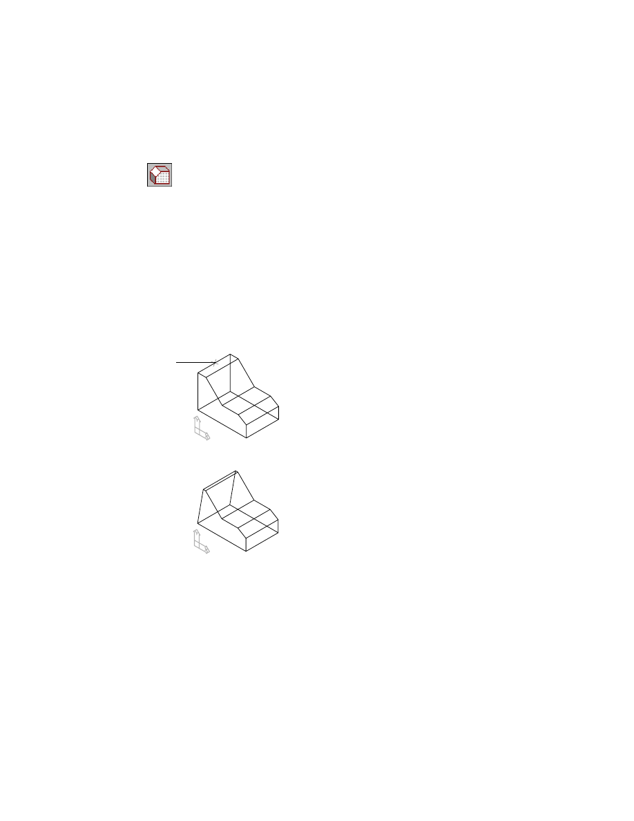
A face draft can also be applied from an existing edge.
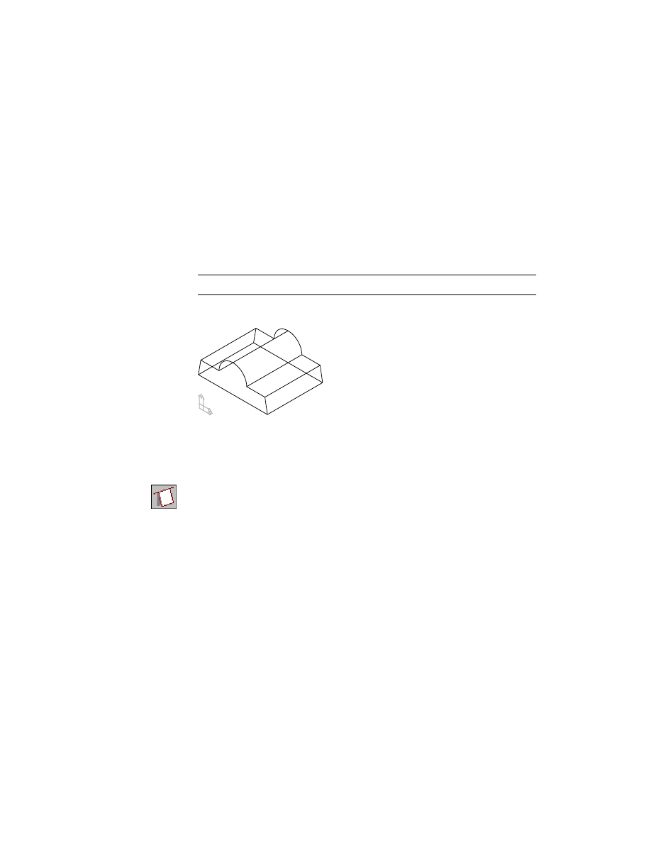
To create a face draft from a fixed edge
1
Create a face draft.
Context Menu
In the graphics area, right-click and choose Placed
Features ➤ Face Draft.
In the Face Draft dialog box, specify:
Type:
From Edge
Angle:
Enter 10
Choose Draft Plane.
196
|
Chapter 10
Creating Placed Features
2
Respond to the prompts as follows:
Select draft plane (planar face or work plane):
Specify the back face
Enter an option [Next/Accept] <Accept>:
Enter n to cycle to the back face, or press
ENTER
Draft direction [Flip/Next] <Accept>:
Enter f to flip the arrow away from the part, or press
ENTER
3
In the Face Draft dialog box, specify:
Faces to Draft:
Add
4
Continue on the command line.
Select faces to draft (ruled faces only):
Specify the bottom face
Select faces to draft (ruled faces only):
Press
ENTER
Select fixed edge:
Specify the bottom edge of the back face
Select fixed edge:
Press
ENTER
5
In the Face Draft dialog box, choose OK to exit.
Draft is applied to the bottom face.
Next, create a shadow draft along the circular face of the part.
Creating Face Drafts
|
197
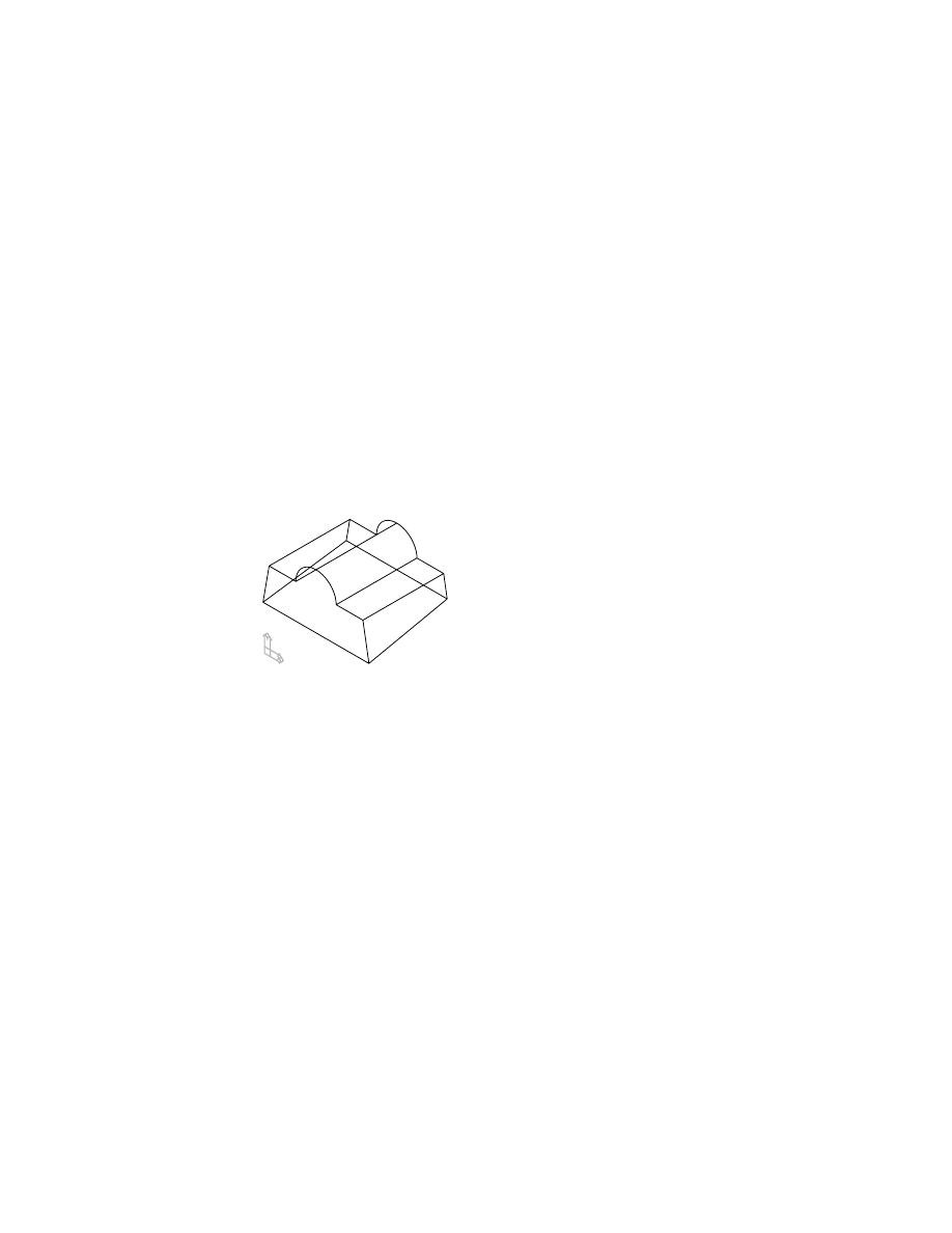
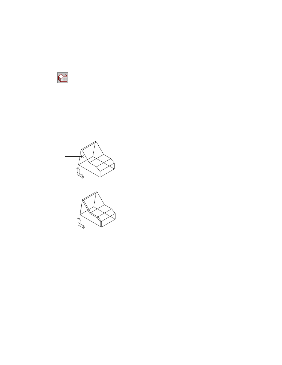
To create a shadow draft
1
Create the shadow draft.
Context Menu
In the graphics area, right-click and choose Placed
Features ➤ Face Draft.
In the Face Draft dialog box, specify:
Type:
Shadow
Angle:
Enter 45
Choose Draft Plane.
2
Respond to the prompts as follows:
Select draft plane (planar face or work plane):
Specify the top right face
Enter an option [Next/Accept] <Accept>:
Enter n to cycle to the top right face or press
ENTER
Draft direction [Flip/Accept] <Accept>:
Enter f to flip the arrow away from the part or press
ENTER
3
In the Face Draft dialog box, specify:
Faces to Draft:
Add
4
Continue on the command line.
Select faces to draft (ruled faces only):
Specify the cylindrical face
Enter an option [Next/Accept] <Accept>:
Enter n to cycle to the cylindrical face or press
ENTER
Select faces to draft (ruled faces only):
Press
ENTER
5
In the Face Draft dialog box, choose OK to exit.
Your part should look like this.
The Browser contains three face draft icons nested below the FDRAFT_1 part
definition.
Save your file.
Next, you modify one of the face drafts you just created.
198
|
Chapter 10
Creating Placed Features
Editing Face Drafts
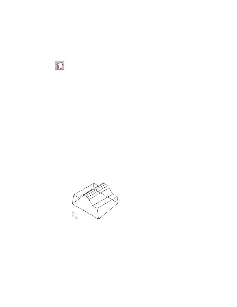
To modify a face draft, you change the parameters that control it.
To edit a face draft
1
Use
AMEDITFEAT
to change FaceDraft2, responding to the prompts.
Context Menu
In the graphics area, right-click and choose Edit Features
➤ Edit.
Enter an option [Sketch/surfCut/Toolbody/select Feature] <select Feature>:
Specify the part
Enter an option [Next/Accept] <Accept>: ExtrusionBlind1:
Enter n
Enter an option [Next/Accept] <Accept>: FaceDraft1:
Enter n
Enter an option [Next/Accept] <Accept>: FaceDraft2:
Press
ENTER
2
In the Face Draft dialog box, change the Angle to 5. Choose OK.
3
Continue on the command line.
Select object:
Press
ENTER
4
Use
AMUPDATE
to update the part, responding to the prompt.
Context Menu
In the graphics area, right-click and choose Update Part.
Your part should look like this.
Save your file.
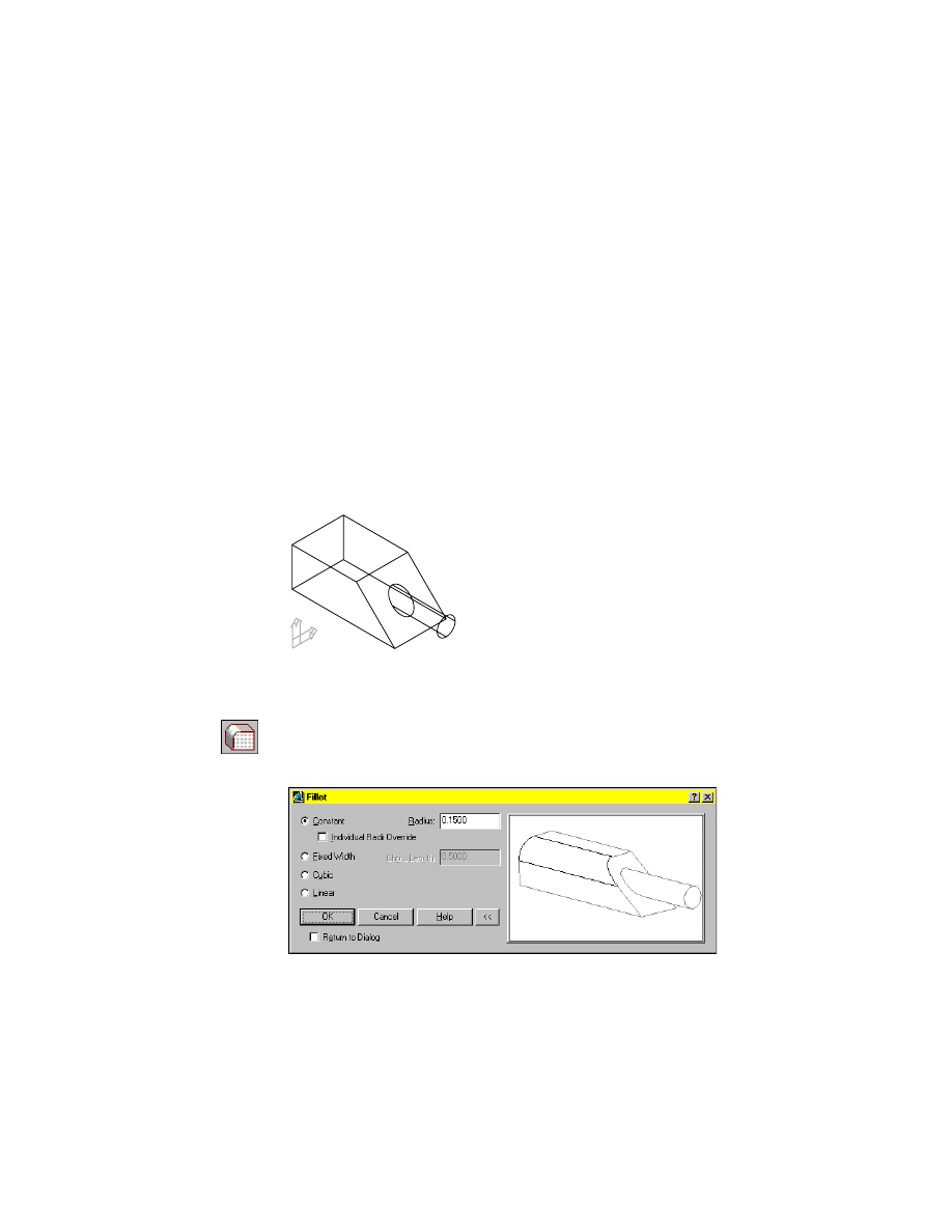
Creating Fillet Features
|
199
Creating Fillet Features
Fillet features can range from simple constant fillets to complex cubic fillets.
Mechanical Desktop creates the following fillet types:
■
Constant
■
Fixed width
■
Linear
■
Cubic
A constant fillet has one radius defining it. A fixed width fillet is controlled
by a chord length. Linear and cubic fillets have a radius at each vertex of the
selected edges that you are filleting. A linear fillet has a straight transition
from one vertex to the next. A cubic fillet has a continually changing radius
from one vertex to the next.
Activate FILLET_1, and zoom to it. Turn off the visibility of F-DRAFT_1.
To create a constant radius fillet
1
Use
AMFILLET
to create a constant radius fillet.
Context Menu
In the graphics area, right-click and choose Placed
Features ➤ Fillet.
In the Fillet dialog box, choose Constant and specify a radius of .15.
Choose OK.
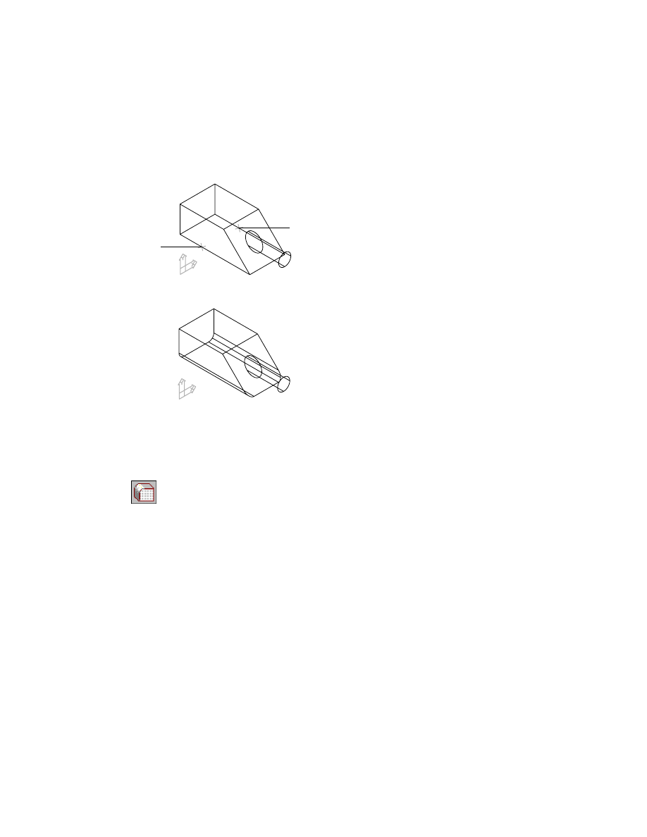
200
|
Chapter 10
Creating Placed Features
2
Continue on the command line.
Select edges or faces to fillet:
Specify an edge (1)
Select edges or faces to fillet:
Specify an edge (2), and press
ENTER
The fillets are applied to your part.
Next, create a fixed width fillet where the cylindrical extrusion meets the
angled face.
To create a fixed width fillet
1
Use
AMFILLET
to create a fixed width fillet.
Context Menu
In the graphics area, right-click and choose Placed
Features ➤ Fillet.
In the Fillet dialog box, choose Fixed Width and specify a chord length of .1.
Then choose OK.
2
Continue on the command line.
Select edges:
Specify the circular edge on the angled face
1
2
Creating Fillet Features
|
201
Your part should look like this.
Create a linear fillet along the top left edge.
To create a linear fillet
1
Create a linear fillet.
Context Menu
In the graphics area, right-click and choose Placed
Features ➤ Fillet.
In the Fillet dialog box, choose Linear, then choose OK.
2
Continue on the command line.
Select edge:
Specify the top left edge
Select radius:
Specify the back radius symbol
Enter radius <0.5000>:
Enter .35 and press
ENTER
Select radius:
Specify the front radius symbol
Enter radius <0.0000>:
Enter .15 and press
ENTER
Select radius:
Press
ENTER
Your part should look like this.
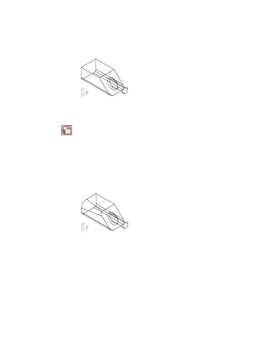
You create a cubic fillet in the same way you create a linear fillet. Cubic and
linear fillets differ because a cubic fillet is a blend on constantly changing
radii from one vertex to the next.
202
|
Chapter 10
Creating Placed Features
To create a cubic fillet
1
Create a cubic fillet.
Context Menu
In the graphics area, right-click and choose Placed
Features ➤ Fillet.
In the Fillet dialog box, choose Cubic, then choose OK.
2
Continue on the command line.
Select edge:
Specify the top right edge at the back of the part
Select radius or [Add vertex/Clear/Delete vertex]:
Specify the back radius symbol
Enter radius <0.5000>:
Enter .5 and press
ENTER
Select radius or [Add vertex/Clear/Delete vertex]:
Specify the front radius symbol
Enter radius <0.0000>:
Enter .1 and press
ENTER
Select radius or [Add vertex/Clear/Delete vertex]:
Press
ENTER
Your part should look like this.
The Desktop Browser contains four fillet icons nested under FILLET_1.
Save your file.
Editing Fillet Features
Like all placed features, fillets are modified by changing the parameters that
control them.
Editing Fillet Features
|
203
To edit a fillet
1
Use
AMEDITFEAT
to modify the cubic fillet, responding to the prompts.
Context Menu
In the graphics area, right-click and choose Edit Features
➤ Edit.
Enter an option [Sketch/surfCut/Toolbody/select Feature] <select Feature>:
Specify Fillet4
Enter an option [Next/Accept] <Accept>:
Enter n to cycle to Fillet4 or press
ENTER
Select object:
Specify the .1 radius
Enter Radius <0.100000000>:
Enter .5 and press
ENTER
Select object:
Specify the original .5 radius
Enter Radius <0.500000000>:
Enter .1 and press
ENTER
Select object:
Press
ENTER
2
Use
AMUPDATE
to update the part, responding to the prompt.
Context Menu
In the graphics area, right-click and choose Update Part.
Your part should look like this.
Save your file.
Delete some or all of the fillets you created in these procedures, and replace
them with your own fillets to change the shape of your part.
204
|
Chapter 10
Creating Placed Features
Creating Chamfer Features
A chamfer feature is a bevelled face created between two existing faces on a
part. Chamfers can be created with an equal distance, two different distances,
or a distance and an angle. You can select an edge or a face to place a chamfer.
If one or more of the edges of a face you want to chamfer have been altered,
you need to use the edge selection method to place chamfers around that face.
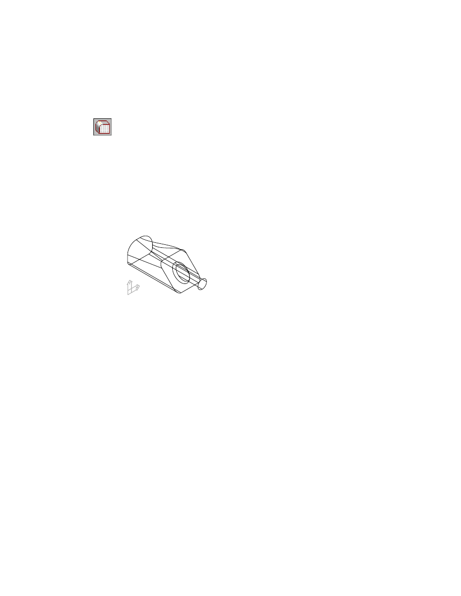
First, activate CHAMFER_1 and zoom in on the part. Turn off the visibility of
FILLET_1.
The part contains a simple extrusion.
To create a chamfer defined by an equal distance
1
Use
AMCHAMFER
to create the chamfer.
Context Menu
In the graphics area, right-click and choose Placed
Features ➤ Chamfer.
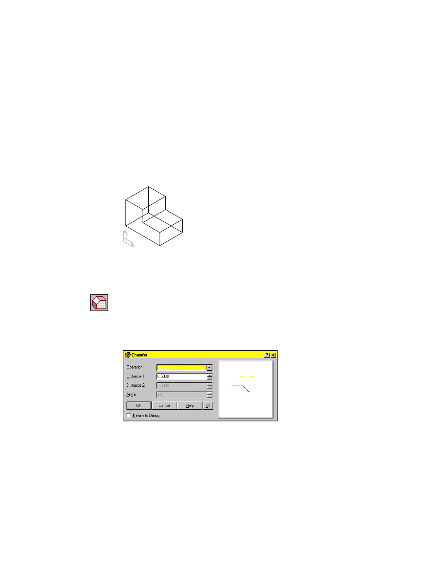
In the Chamfer dialog box, specify:
Operation:
Equal Distance
Distance1:
Enter .5
Creating Chamfer Features
|
205
2
Choose OK and respond to the prompts as follows:
Select edges or faces to chamfer:
Specify an edge (1)
Select edges or faces to chamfer <continue>:
Press
ENTER
Mechanical Desktop creates the chamfer along the edge you selected.
You can also create chamfers by specifying two different distances. After you
select the edge, you specify a face for Distance 1, called the base distance. Dis-
tance 2 is applied to the other face.
1
206
|
Chapter 10
Creating Placed Features
To create a chamfer defined by two distances
1
Use
AMCHAMFER
to create the chamfer.
Context Menu
In the graphics area, right-click and choose Placed
Features ➤ Chamfer.
In the Chamfer dialog box, specify:
Operation:
Two Distances
Distance1:
Enter .25
Distance2:
Enter .15
Choose OK.
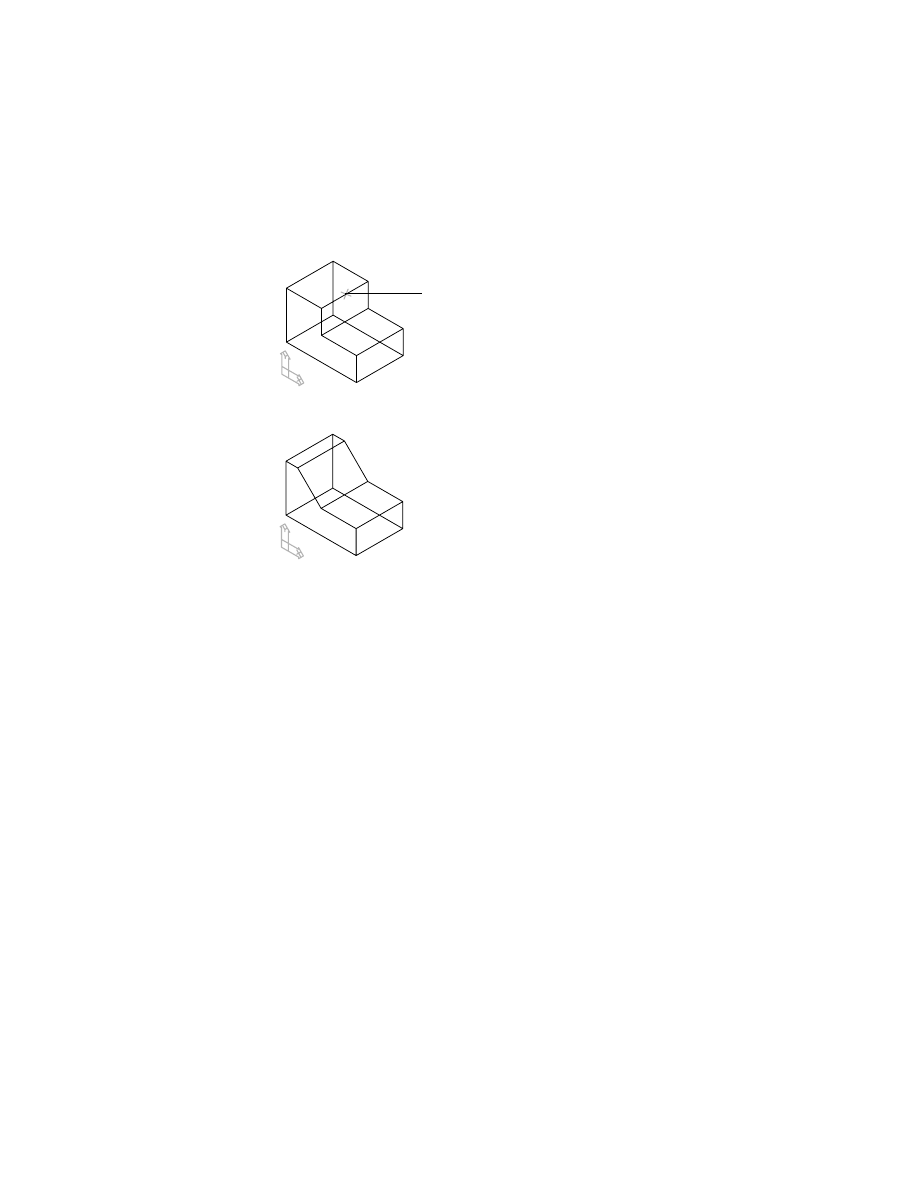
2
Respond to the prompts as follows:
Select an edge or face to chamfer:
Specify the edge (2)
Press <ENTER> to continue:
Press
ENTER
The specified face will be used for base distance.
Specify face for first chamfer distance (base) [Next/Accept] <Accept>:
Press
ENTER
Mechanical Desktop calculates and displays the chamfer. Your drawing
should look like this.
You can create a chamfer defined by a distance and an angle. You select an
edge, and then specify the face for the angle. The distance is applied to the
other face.
2
Creating Chamfer Features
|
207
To create a chamfer defined by a distance and angle
1
Define the chamfer.
Context Menu
In the graphics area, right-click and choose Placed
Features ➤ Chamfer.
In the Chamfer dialog box, specify:
Operation:
Distance and Angle
Distance1:
Enter 1
Angle:
Enter 10
Choose OK.
2
Continue on the command line.
Select an edge or face to chamfer:
Specify the edge (3)
Press <ENTER> to continue:
Press
ENTER
The specified face will be used for base distance.
Specify face for chamfer distance (base) [Next/Accept] <Accept>:
Press
ENTER
Mechanical Desktop calculates and displays the chamfer.
If you need to place a chamfer on all sides of a face, you can select the face
and place a chamfer on all of the edges in one operation. This works on faces
where none of the edges to be chamfered have been altered.
3
208
|
Chapter 10
Creating Placed Features
To create a chamfer on all edges of a face
1
Define the chamfer.
Context Menu
In the graphics area, right-click and choose Placed
Features ➤ Chamfer.
In the Chamfer dialog box, specify:
Operation:
Equal Distance
Distance1:
Enter .04
Choose OK.
2
Continue on the command line.
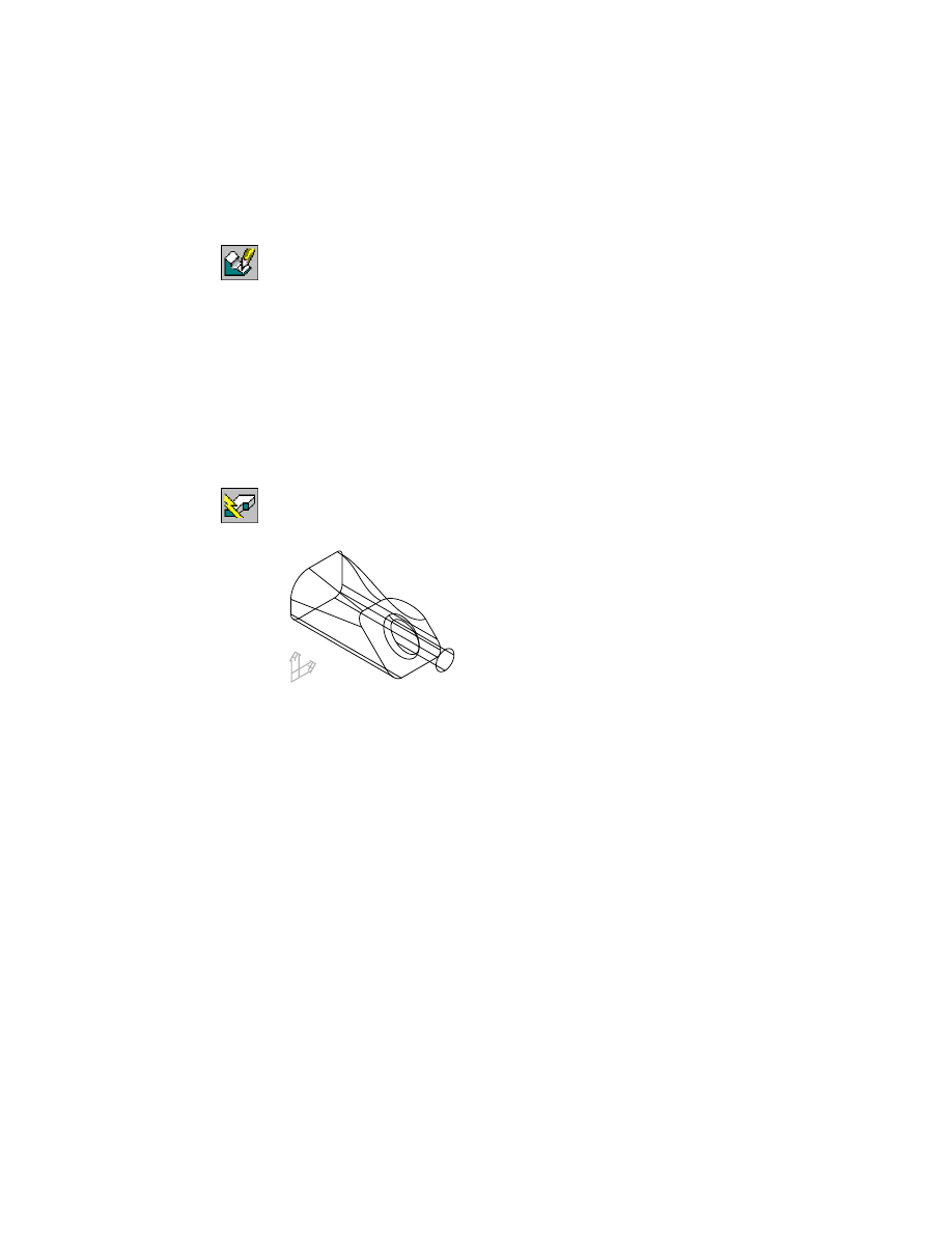
Select edges or faces to chamfer:
Select the face (4)
Enter an option [Next/Accept] <Accept>:
Press
ENTER
Select edges or faces to chamfer <continue>:
Press
ENTER
A chamfer is placed on all edges of the face you selected.
Four chamfer icons are nested below the CHAMFER_1 part definition in the
Browser.
Save your file.
Editing Chamfer Features
As with all placed features, chamfers can be edited by selecting the feature,
changing parameters, and updating the part. Try editing some of the chamfer
features you created in this section.
4
Creating Shell Features
|
209
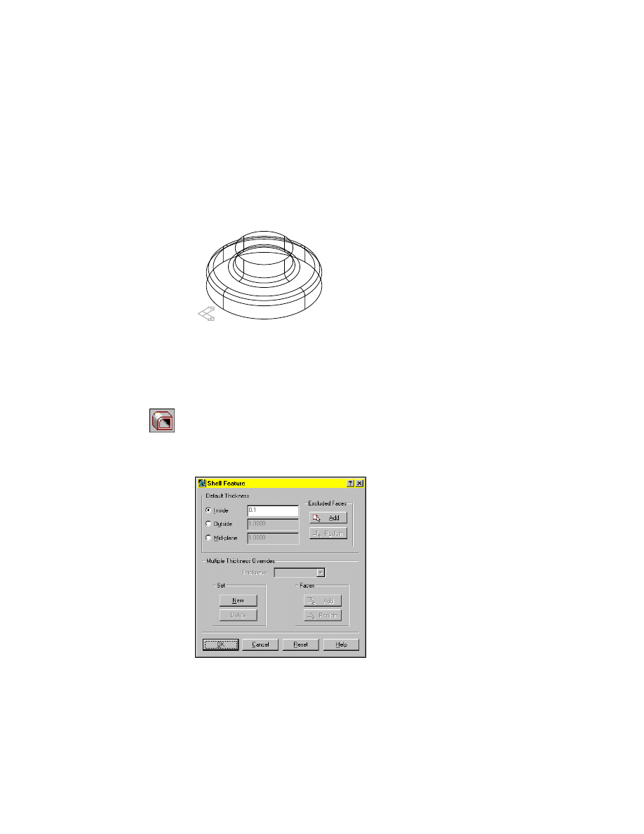
Creating Shell Features
You use shell features to hollow parts that are used in a variety of industrial
applications. For example, you shell parts to create molds, castings, contain-
ers, bottles, and cans.
Activate SHELL_1 and zoom in on it. Turn off the visibility of CHAMFER_1.
The part is constructed from two extrusions and one fillet feature.
Next, you shell the part, and then modify it to exclude the top and bottom faces.
To create a shell feature
1
Use
AMSHELL
to create a shell.
Context Menu
In the graphics area, right-click and choose Placed
Features ➤ Shell.
In the Shell Feature dialog box, specify:
Default Thickness:
Inside:
Enter .1
Choose OK to exit the dialog box.
210
|
Chapter 10
Creating Placed Features
Mechanical Desktop offsets all faces by the thickness you specified in the
Shell Feature dialog box.
2
Change to a front view for a better view of the feature.
Desktop Menu
View ➤ 3D Views ➤ Front
Save your file.
Next, you edit the feature to exclude the top and bottom faces from the shell.
Editing Shell Features
You modify shell features by changing the parameters that control them.
Shells can also have multiple thickness overrides applied to individual faces.
You learn to use multiple thickness overrides in chapter 14, “Creating Shells.”
To edit a shell feature
1
Return to an isometric view.
Desktop Menu
View ➤ 3D Views ➤ Front Right Isometric
2
Use
AMEDITFEAT
to modify the shell feature, responding to the prompt.
Context Menu
In the graphics area, right-click and choose Edit Features
➤ Edit.
Enter an option [Sketch/surfCut/Toolbody/select Feature] <select Feature>:
Specify the shell feature
3
In the Shell Feature dialog box under Excluded Faces, choose Add.
Editing Shell Features
|
211
4
Continue on the command line.
Select faces to exclude:
Specify the bottom face
Enter an option [Accept/Next] <Accept>:
Enter n to cycle to the bottom face
Enter an option [Accept/Next] <Accept>:
Press
ENTER
Select faces to exclude:
Specify the top face
Enter an option [Accept/Next] <Accept>:
Enter n to cycle to the top face
Enter an option [Accept/Next] <Accept>:
Press
ENTER
Select faces to exclude:
Press
ENTER
Choose OK to exit the Shell Feature dialog box.
5
Use
AMUPDATE
to update your part, responding to the prompt.
Context Menu
In the graphics area, right-click and choose Update Part.
Hide the hidden lines to see your part better. Because the part is cylindrical,
to display silhouette edges, you set the
DISPSILH
system variable to 1 first.
6
Change the setting for
DISPSILH
.
Command
DISPSILH
New value for DISPSILH <0>:
Enter 1
7
Use
HIDE
to hide the hidden lines.
Desktop Menu
View ➤ Hide
Your part should look like this.
8
Return to wireframe display.
Desktop Menu
View ➤ Shade ➤ 3D Wireframe
Save your file.
212
|
Chapter 10
Creating Placed Features
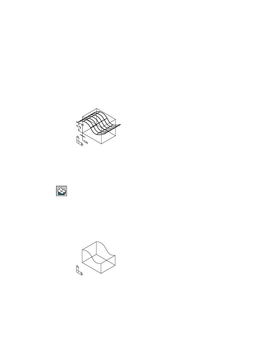
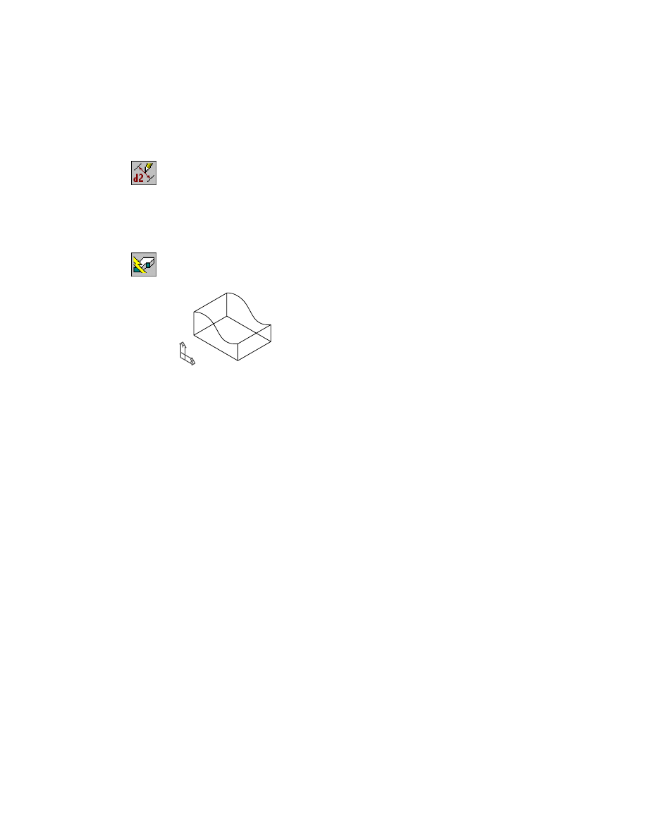
Creating Surface Cut Features
Surface cut features give you the flexibility of combining a parametric part
and a surface. While the surface is not parametric, its position on the part is
controlled by a work point which you can move parametrically.
Surface cut features may be used to add and remove material from a part.
Activate SURFCUT_1 and zoom in to it. Turn off the visibility of SHELL_1.
SURFCUT contains a simple rectangular extrusion, a work point, and a sur-
face. The work point is constrained to the part. You use the work point to
control the position of the surface cut.
To create a surface cut
1
Use
AMSURFCUT
to create a surface cut, responding to the prompts.
Context Menu
In the graphics area, right-click and choose Placed
Features ➤ Surface Cut.
Type=Cut
Select surface or [Type]:
Specify the surface
Select work point:
Specify the work point
Specify portion to remove: [Flip/Accept] <Accept>:
Enter f to flip the arrow away from the part, or press
ENTER
The portion of the part above the surface is cut away, leaving the curved face
of the surface.
Editing Surface Cut Features
|
213
The Browser contains a surface cut icon at the bottom of the feature hierarchy
for SURFCUT_1.
Save your file.
Next, you edit the position of the surface to modify the surface cut feature.
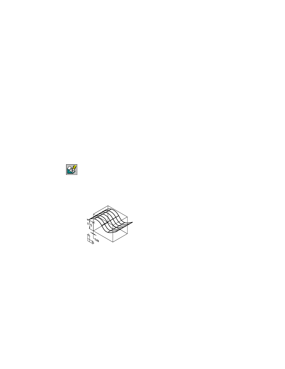
Editing Surface Cut Features
You can modify surface cut features in one of two ways:
■
Parametrically change its position.
■
Manually change the shape of the surface.
In this section, you change the position of the feature by modifying the para-
metric dimensions controlling the work point associated with the surface.
To reposition a surface cut feature
1
Use
AMEDITFEAT
to edit the feature, responding to the prompts.
Context Menu
In the graphics area, right-click and choose Edit Features
➤ Edit.
Enter an option [Sketch/surfCut/Toolbody/select Feature] <select Feature>:
Enter c
Select surfcut feature:
Specify the surface
The surface is recovered.
In this state, you can modify the actual shape of the surface by editing its
grips, or change the location of the work point that controls the position of
the surface on the part.
214
|
Chapter 10
Creating Placed Features
2
Use
AMMODDIM
to change the vertical dimension controlling the work
point, responding to the prompts.
Context Menu
In the graphics area, right-click and choose Dimensioning
➤ Edit Dimension.
Select dimension to change:
Specify .75
New value for dimension <.75>:
Enter .5
Select dimension to change:
Press
ENTER
3
Use
AMUPDATE
to update the part, responding to the prompt.
Context Menu
In the graphics area, right-click and choose Update Part.
The part is updated to reflect the new location for the surface cut feature.
4
Save your file.
Experiment with the surface by editing its control points. Use
AMEDITFEAT
to
recover the surface. Then select a grip to activate it. When you move the grip
to another location you will see the surface deform. Update your part to
examine the effect of your changes.
Creating Pattern Features
A pattern is a collection of duplicate features. You can create patterns with
rectangular, nonorthogonal rectangular, polar, and axial configurations, and
patterns of other pattern features.
By default, a pattern feature uses the active sketch plane as the distribution
plane for pattern instances.
Creating Pattern Features
|
215
While selecting a feature set for a pattern, you select each graphically depen-
dent feature individually. You can select multiple independent features.
Single instances in a pattern can be made independent of an existing pattern
feature. Once a feature is independent, it can be altered while its position
remains intact.
In this tutorial, you create several different types of patterns, using both
incremental and included spacing. In the polar pattern exercise, you make
one instance independent and alter it.
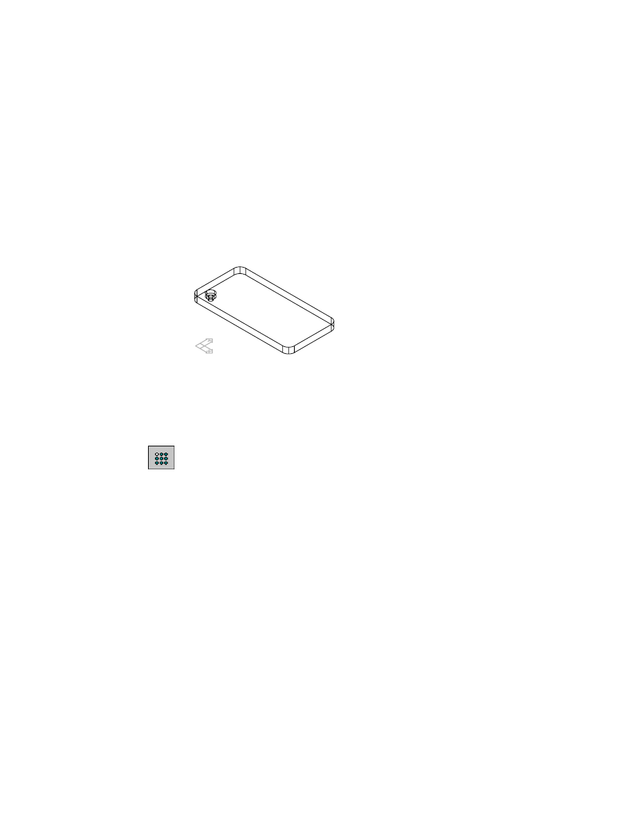
Activate R-PATTERN_1, and zoom to it. Turn off the visibility of SURFCUT_1.
R-PATTERN contains a filleted plate and one counterbore hole. You create a
rectangular pattern of the hole with incremental spacing and alignment to
an edge.
To create a rectangular pattern
1
Use
AMPATTERN
to create a rectangular pattern, responding to the prompts.
Context Menu
In the graphics area, right-click and choose Placed
Features ➤ Rectangle Pattern.
Select features to pattern:
Specify the hole
Select features to pattern or [liSt/Remove] <Accept>:
Press
ENTER
If you use multiple features to create a pattern, you select each one individu-
ally, regardless of feature dependencies.
216
|
Chapter 10
Creating Placed Features
2
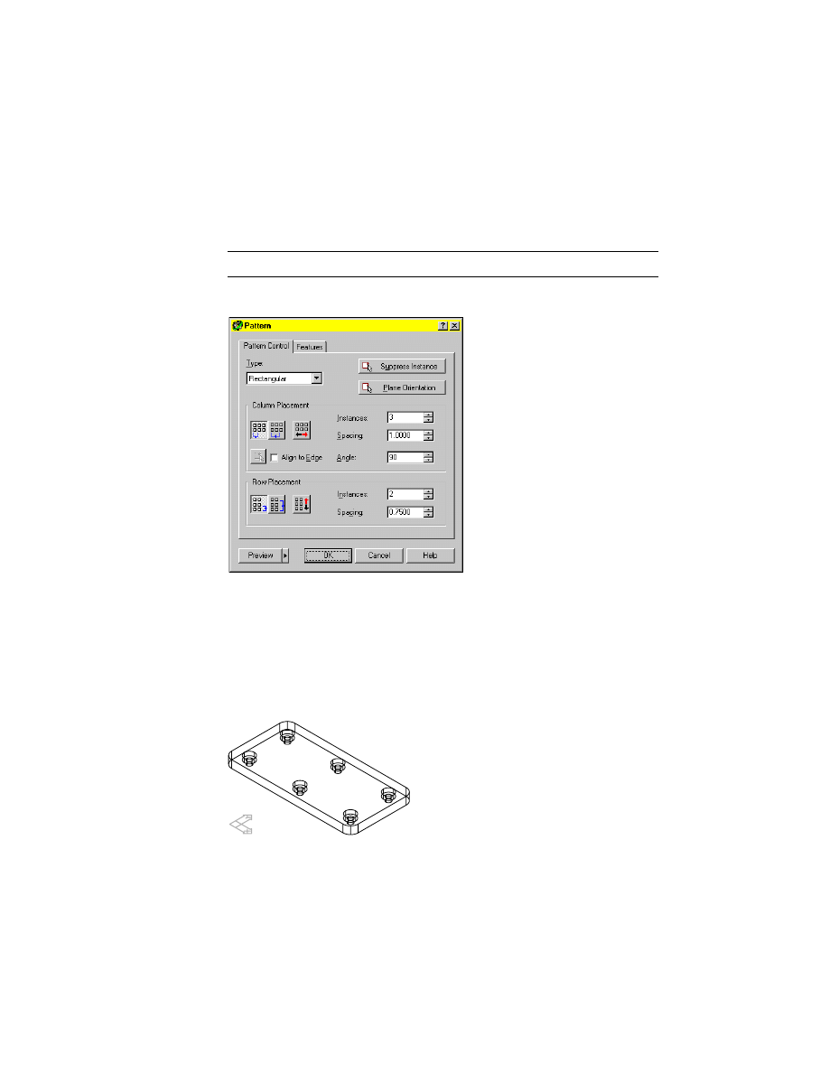
In the Pattern dialog box, specify:
Type:
Rectangular
Column Placement:
Choose Incremental Spacing, the leftmost button
Row Placement:
Choose Incremental Spacing, the leftmost button
NOTE
Hold the cursor over an icon for a tooltip to identify the icon.
Enter the values shown for column and row instances and spacing.
3
Choose Preview, and view your pattern on the screen.
At this point, you can redefine the pattern by changing your selections in the
Pattern dialog box, and then preview the changes. Preview becomes unavail-
able once the parameters in the dialog box match the display on the screen.
Using the preview image, you can suppress instances of features in patterns.
4
Choose OK to create the pattern and exit the dialog box.
Your drawing should look like this.
Creating Pattern Features
|
217
Use R-PATTERN again to create a nonorthogonal rectangular pattern with
included spacing and a value entered for the angle.
In the Browser, right-click the icon for the pattern you just created, and
choose delete. Verify that the R-PATTERN part is activated.
To create a nonorthogonal rectangular pattern
1
Use
AMPATTERN
to create a nonorthogonal rectangular pattern, responding
to the prompts.
Context Menu
In the graphics area, right-click and choose Placed
Features ➤ Rectangular Pattern.
Select features to pattern:
Specify the hole
Select features to pattern or [liSt/Remove] <Accept>:
Press
ENTER
2
In the Pattern dialog box, in Column Placement, select Included, the second
button from the left. Specify:
Instances:
Enter 3
Angle:
Enter 60
Spacing:
Angle:
Enter 1
In Row Placement, select Included, and specify:
Instances:
Enter 2
Spacing:
Enter .75
Choose OK.
The hole pattern is created at a 60-degree angle from the side of the part.
218
|
Chapter 10
Creating Placed Features
Next, create a full circle polar pattern using a work axis as the center and a
specified number of instances. When you choose a different pattern type, the
appropriate options are displayed in the Pattern dialog box.
Activate P-PATTERN_1 and zoom to the part.
The part is constructed with a circular plate and two holes.
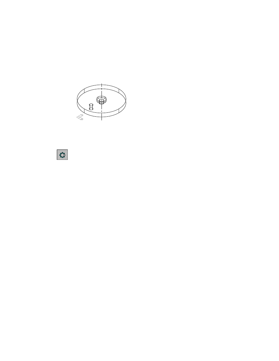
To create a polar pattern
1
Use
AMPATTERN
create a polar pattern, responding to the prompts.
Context Menu
In the graphics area, right-click and choose Placed
Features ➤ Polar Pattern.
Select features to pattern:
Specify Hole2
Enter an option [Next/Accept] <Accept>:
Press
ENTER
Select features to pattern or [liSt/Remove] <Accept>:
Press
ENTER
Valid selections: work point, work axis, linear edge, cylindrical edge/face
Select rotational center:
Specify the work axis
2
In the Pattern dialog box, specify:
Polar Placement:
Choose Full Circle
Instances:
Enter 5
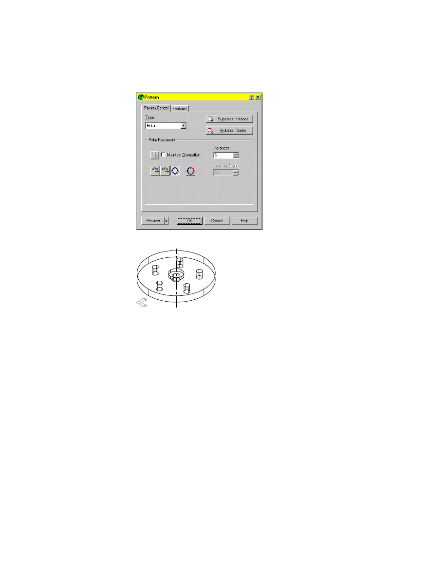
Creating Pattern Features
|
219
Choose Preview and view the pattern. Then choose OK.
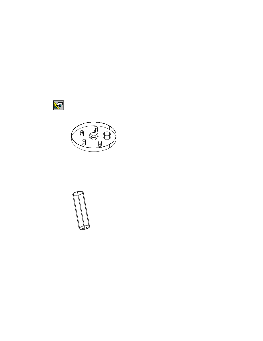
Next, make one instance of the pattern independent and then alter it.
To make a pattern instance independent
1
Select the pattern instance to make independent.
Browser
Right-click PolarPattern, and choose Independent
Instance.
Respond to the prompts.
Select feature pattern or array instance:
Select hole instance #4
An independent hole based on a work point is copied from the selected hole
instance. Dependent features are maintained and copied with the pattern
instance.
Icons for the work point and independent Hole3 are displayed in the
Browser.
220
|
Chapter 10
Creating Placed Features
The previous hole instance is suppressed. It can be reclaimed using the
Pattern dialog box.
2
Use
AMEDITFEAT
to resize the independent pattern instance.
Browser
Right-click the independent Hole4, and choose Edit.
The Hole dialog box is displayed.
3
In the Hole dialog box, change the diameter to .4, and choose OK.
4
Use
AMUPDATE
to update the part, responding to the prompt.
Context Menu
In the graphics area, right-click and choose Update Part.
The Hole3 is resized, while it maintains its position in the pattern.
You can create axial patterns, and you can create a pattern from another
pattern.
In the Browser, right-click A-PATTERN_1 and choose Activate Part. Right-
click A-PATTERN_1 again, and choose Zoom to. Turn off the visibility of
P-PATTERN_1.
A-PATTERN_1 contains a cylinder with a polar pattern of three holes. In this
exercise, you use this polar pattern to create an axial pattern, specifying a
work axis as the rotation center. You specify the number of instances, and
incremental column and row placement.
After you create the axial pattern, you use it to create another polar pattern.
In the Browser, expand A-PATTERN_1.
Creating Pattern Features
|
221
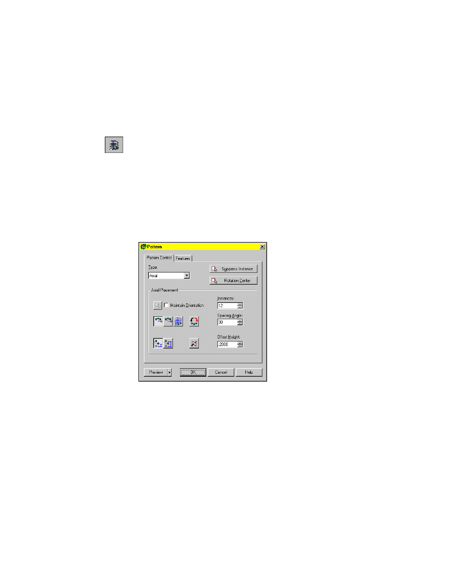
To create an axial pattern
1
In the Browser, under A-PATTERN_1, right-click WorkAxis1 and choose
Visible.
2
Use
AMPATTERN
to create an axial pattern, responding to the prompts.
Browser
In the Browser, right-click Polar Pattern1 and choose
Pattern ➤ Axial.
Valid selections: work point, work axis, linear edge, cylindrical edge/face
Select rotational center:
Specify the work axis
In the Pattern dialog box, in Axial Placement, specify:
Instances:
Enter 12
Column Placement:
Select Incremental Angle, the button on the left
Spacing Angle:
Enter 30
Row Placement:
Select Incremental Offset, the button on the left
Offset Height:
Enter .2
3
In the Pattern Dialog box, press Preview to view the pattern, then press OK.
The axial pattern is created on the surface of the cylinder. Hide the hidden
lines to see your part better. Because the part is cylindrical, to display silhouette
edges, you set the
DISPSILH
system variable to 1 first.
4
Change the setting for
DISPSILH
.
Command
DISPSILH
New value for DISPSILH <0>:
Enter 1
222
|
Chapter 10
Creating Placed Features
5
Use
HIDE
to hide the hidden lines.
Desktop Menu
View ➤ Hide
Your part should look like this.
6
Finish the part by using the new axial pattern to create another polar pattern.
Browser
In the Browser, right-click Axial Pattern1 and choose
Pattern ➤ Polar.
Select Rotational Center:
Select the work axis
7
In the Pattern dialog box, specify:
Polar Placement:
Select Incremental Angle
Instances:
Enter 2
Spacing Angle:
Enter 180
Choose OK.
8
Use HIDE to hide the hidden lines.
Desktop Menu
View ➤ Hide
Your finished part should look like this.
Editing Pattern Features
|
223
Editing Pattern Features
You edit pattern features in the Pattern dialog box. In the Pattern Control
tab, you modify the instancing controls. In the Features tab, you redefine the
features in the pattern. Once a pattern is created, you cannot change the pat-
tern type.
When you delete a feature from a pattern set, you also remove other graphi-
cally dependent features that are children of that feature, such as fillets. If
you want to add a feature to the set, a feature rollback is required.
A pattern is associative to the original feature that was patterned. When you
modify the sketch of a patterned feature, you also modify the entire pattern.
Use the Pattern dialog box to preview and redefine the orientation of the dis-
tribution plane at any time. If you want to change the distribution plane to
a different plane, a feature rollback is required.
Try editing the rectangular and polar patterns you created in this section.
Editing Array Features
Although you cannot create a new array, you can edit a previously-created
array by editing the dimensions and instance constraints of the array using
command line prompts. There is no dialog box available for editing arrays.
Pre-existing array features cannot be migrated to pattern features.
The following procedure is available only when you open a drawing file that
contains a previously-created array.
To edit a previously-created array
9
Use
AMEDITFEAT
to edit a previously created array, responding to the
prompts.
Context Menu
Right-click the graphics area and choose Edit Features ➤
Edit.
Enter an option [Independent array instance/Sketch/surfCut/Toolbody/select
Feature] <select Feature>:
Enter I
Follow the command line prompts to edit the dimensions and instance con-
straints for your particular array.
224
|
Chapter 10
Creating Placed Features
Creating Copied Features
You can copy a feature from any part, and place it on your active part on the
current sketch plane. If the feature you select is on the active part, you can
specify that the copy is independent. That way, you can modify either feature
without affecting the other. If you do not specify that the copy is indepen-
dent, or you copy a feature from an inactive part, any changes made to either
the feature or the copy are reflected in both features.
Once copied, you can constrain the copied feature to the part by editing the
sketch.
NOTE
You cannot copy base features.
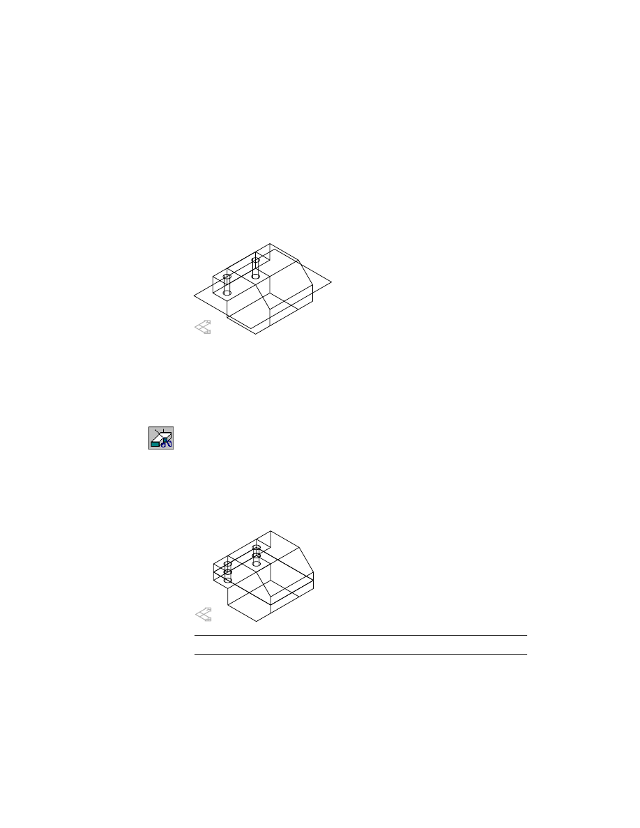
Activate CFEAT_1 and zoom in on the part. Turn off the visibility of
P-PATTERN_1.
The part has a blind slot on the left front face. The current sketch plane lies
on the right front face. You copy the feature to the current sketch plane and
then constrain it to the part.
Creating Copied Features
|
225
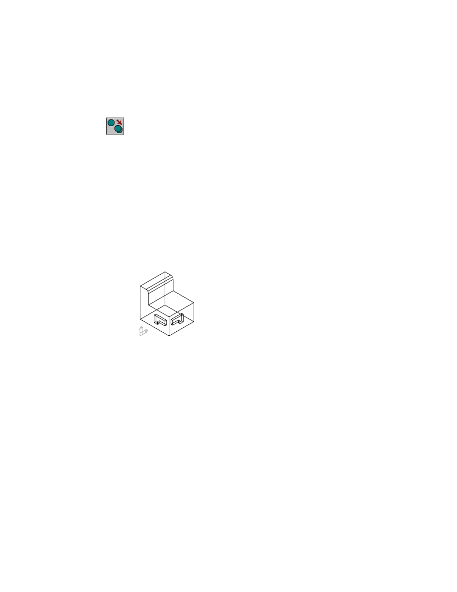
To copy a feature
1
Use
AMCOPYFEAT
to create a copy of the slot, responding to the prompts.
Context Menu
In the graphics area, right-click and choose Edit Features
➤ Copy.
Select feature to be copied (from any part):
Specify the blind extrusion
Parameters=Independent
Specify location on the active part [Parameters]:
Specify a location on the current sketch plane
Parameters=Independent
Specify location on the active part [Parameters/Rotate/Flip]:
Enter f
Parameters=Independent
Specify location on the active part [Parameters/Rotate/Flip]:
Enter r
Parameters=Independent
Specify location on the active part [Parameters/Rotate/Flip]:
Enter r
Parameters=Independent
Specify location on the active part [Parameters/Rotate/Flip]:
Respecify the location or press
ENTER
Your drawing should look like this.
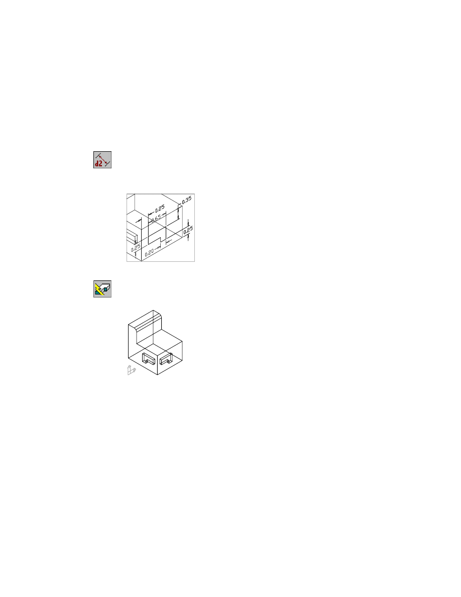
Next, you constrain the copied feature to the part by editing the feature’s
sketch. Three dimensions constrain the original feature to the part. You
create three identical dimensions to constrain the new feature to the part.
226
|
Chapter 10
Creating Placed Features
To constrain a copied feature
1
Use the Browser to edit the sketch.
Browser
Right-click ExtrusionBlind3 and choose Edit Sketch.
2
Use
AMPARDIM
to add three parametric dimensions to constrain the sketch
to the part.
Context Menu
In the graphics area, right-click and choose Dimensioning
➤ New Dimension.
3
Place a 0.25 horizontal dimension, a 0.35 vertical dimension, and a 0.25 ver-
tical dimension as illustrated below.
4
Use
AMUPDATE
to update your part, responding to the prompt.
Context Menu
In the graphics area, right-click and choose Update Part.
Enter an option [active Part/aLl parts] <active Part>:
Press
ENTER
Save your file.
Editing Copied Features
|
227
Editing Copied Features
You can edit a copied feature by modifying the feature itself, or by modifying
its location on the part. If the copy is dependent on the original feature, or if
it was created from a feature on an inactive part, any changes to either feature
are reflected in both features.
The copied feature you created is independent from the original feature. Try
modifying the shape of the copied feature, using what you learned earlier in
this tutorial about editing extrusions.
Creating Combined Features
You create combined features by combining two parts, using Boolean opera-
tions. The part that is combined is called the toolbody. You position the tool-
body on the base part using assembly constraints, and then combine the parts.
Activate COMBINEFEAT_1 and zoom in so you can see it and TOOLBODY_1.
Turn off the visibility of CFEAT_1.
The parts have already been constrained with assembly constraints. You
learn to use assembly constraints in chapter 16, “Assembling Parts.”
COMBINEFEAT_1
TOOLBODY_1
228
|
Chapter 10
Creating Placed Features
To create a combined feature
1
Use
AMCOMBINE
to create a combined feature, responding to the prompts.
Context Menu
In the graphics area, right-click and choose Placed
Features ➤ Combine.
Enter a parametric Boolean operation [Cut/Intersect/Join] <Cut>:
Enter j
Select a part (toolbody) to be joined:
Specify TOOLBODY_1
The parts are combined into one part.
2
Look at the Browser. Expand the Combine1 icon nested under
COMBINEFEAT_1. TOOLBODY_1 has become a combined feature and is
no longer a separate part definition.
Save your file.
Editing Combined Features
Combined features can be modified by changing the assembly constraints
controlling the base part and the toolbody, by editing the base part, or by
making changes to the toolbody. You’ll learn more about combining parts
and editing toolbodies in chapter 17, “Combining Parts.”
Creating Part Splits
|
229
Creating Part Splits
You can split parts by creating a planar or a nonplanar split feature. A planar
split uses a work plane, existing part face, or a split line. A nonplanar split
uses a constrained sketch and a Boolean operation.
Activate P-SPLIT_1 and zoom in on the part. Turn off the visibility of
COMBINEFEAT_1.
The part is a simple extrusion with two holes and a work plane located at the
midplane of the part. You split the part into two distinct part definitions with
the work plane.
To create a part split
1
Use
AMPARTSPLIT
to split the part, responding to the prompts.
Context Menu
In the graphics area, right-click and choose Placed
Features ➤ Part Split.
Select planar face, work plane, surface, or split line for split:
Specify the work plane
Define side for new part: [Accept/Flip] <Accept>:
Press
ENTER
Enter name of the new part <PART2>:
Press
ENTER
The part is split along the work plane and a new part definition is created.
NOTE
For clarity, the work plane is not shown.
230
|
Chapter 10
Creating Placed Features
2
Expand PART2_1 in the Browser and compare its features with P-SPLIT_1.
Both parts contain a Part Split feature, two holes, and a work plane.
Save your file.
You can also create planar splits with an existing part face, or a split line con-
strained to the part. Next, create a nonplanar split.
Activate N-SPLIT_1 and zoom in on the part. Turn off the visibility of
P-SPLIT_1 and PART2_1.
NOTE
For clarity, the profile’s dimensions are not shown.
You create a nonplanar split by extruding the profile into the part. A new part
definition is created from the volume shared by the part and the extrusion.
To create a non-planar part split
1
Use
AMEXTRUDE
to create the part split.
Context Menu
In the graphics area, right-click and choose Sketched &
Work Features ➤ Extrude.
In the Extrusion Feature dialog box, specify:
Operation:
Split
Termination:
Blind
Distance:
Enter .7
Flip:
Make sure the direction arrow is flipped into the part
Choose OK to exit the dialog box.
Editing Part Splits
|
231
2
Continue on the command line.
Enter name of the new part <PART3>:
Press
ENTER
The part is split and a new part definition is created.
Save your file.
Editing Part Splits
Parts created by a part split can be edited in the same way as the parts they
were created from. The new parts contain identical work geometry, and if any
feature was split, each part contains a version of that feature.
Nonplanar splits are used to create parts that fit together. Face drafts can be
applied to the faces of both parts to make them fit together easier.
Try editing the sketched and placed features that make up the parts you have
split in this section.
You are now ready to create a complex part.

232
Wyszukiwarka
Podobne podstrony:
Atari 8 Bit Demopac 7 Some Special Features
features
Ch10 Q3
ch10
E in T features & nescessity
Ch10 E2
CE Specific features
Ch10 Q1
Ch8 Sketched Features
BW ch10
N Feature Neural Network Human Face Recognition
Audiovisual translation of feature films eng lithuanian
lab8, 2.2.4.11 Lab - Configuring Switch Security Features
Ch10 Q5
HP 5000 D640 Enhanced Features Manual
Ch9 Work Features
new features in version2
CE Specific features
więcej podobnych podstron