
11
HONDA
ACURA
CONTENTS
APPLICATIONS
HONDA / ACURA MANUAL
GENERAL OPERATION
SPECIAL FUNCTIONS
TIPS & HINTS
REMOTE CONTROL PROGRAMMING
11
11
11
11
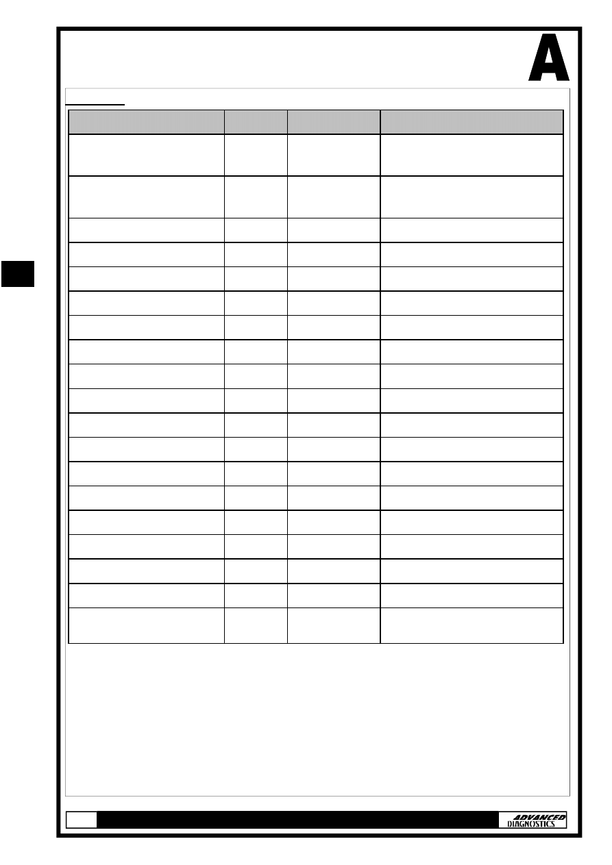
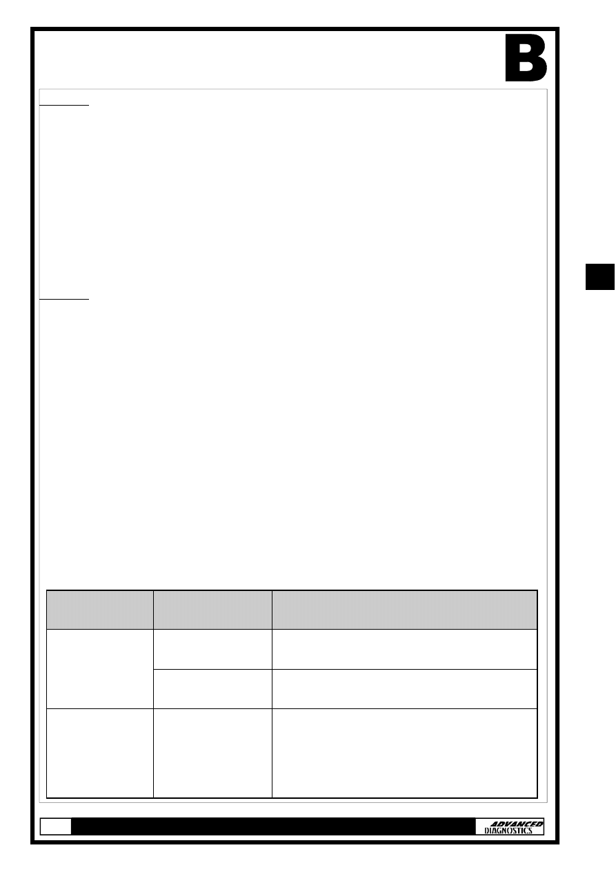
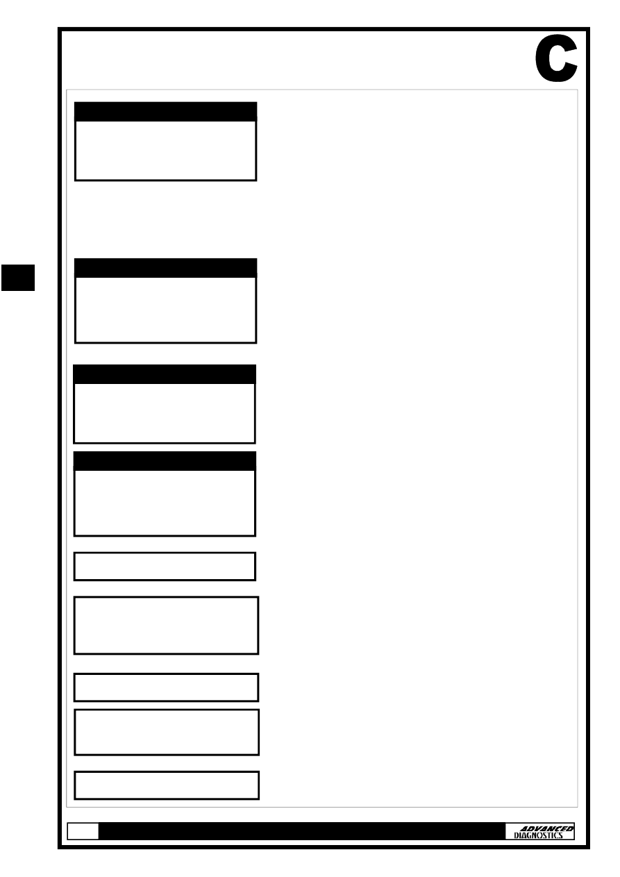
APPLICATIONS
HONDA
VEHICLE
YEAR
SYSTEM
CABLE
CIVIC/ACCORD * 1 >99
TYPE 5
ADC110-B, ADC134 &
ADC140
CIVIC/ACCORD * 2 >99
TYPE 6
ADC110-B, ADC134 &
ADC140
ACCORD
98-02 TYPE 2C
ADC110-B & ADC134
ACCORD
98-02 TYPE 2A
ADC110-B & ADC134
ACCORD
2003
TYPE 4
ADC110-B & ADC134
CIVIC
01-02 TYPE 3
ADC110-B & ADC134
CIVIC
2003
TYPE 3
ADC110-B & ADC134
CR-V
02-03 TYPE 3
ADC110-B & ADC134
ELEMENT
2003
TYPE 3
ADC110-B & ADC134
INSIGHT
00-03 TYPE 2A
ADC110-B & ADC134
ODYSSEY
98-03 TYPE 2A
ADC110-B & ADC134
PILOT
2003
TYPE 2B
ADC110-B & ADC134
S2000
00-03 TYPE 2A
ADC110-B & ADC134
PRELUDE
97-02 TYPE 1A
ADC110-B & ADC134
HRV
ALL
TYPE 2A
ADC110-B & ADC134
JAZZ
ALL
TYPE 3
ADC110-B & ADC134
CIVIC/ACCORD * 2 >99
TYPE 6
ADC134 & ADC141
CIVIC/ACCORD * 1 >99
TYPE 5
ADC134 & ADC141
STREAM
ALL
TYPE 3
ADC110-B & ADC134
*1 USES OLD 5 or 3 PIN ADAPTOR CABLE—BLACK KEY SYSTEM
*2 USES OLD 5 or 3 PIN ADAPTOR CABLE— RED MASTER KEY SYSTEM
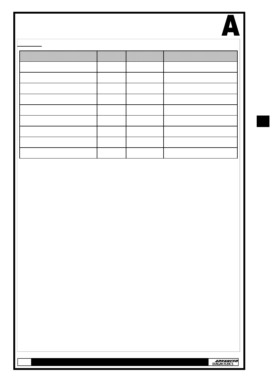
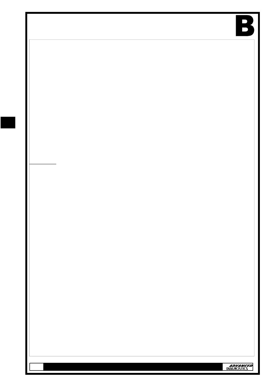
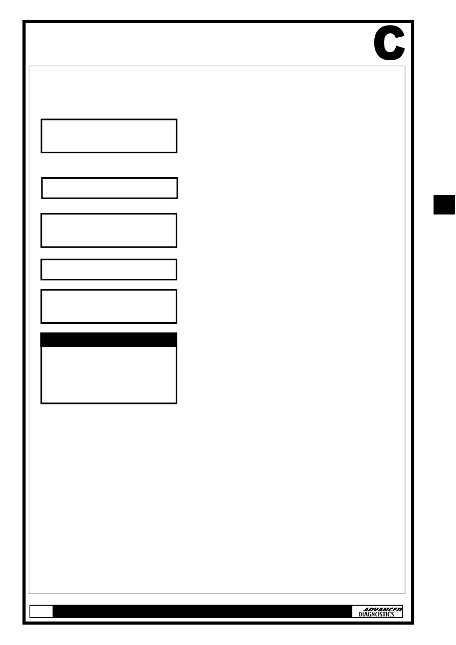
APPLICATIONS
ACURA
*1 USES OLD 5 or 3 PIN ADAPTOR CABLE—BLACK KEY SYSTEM
*2 USES OLD 5 or 3 PIN ADAPTOR CABLE— RED MASTER KEY SYSTEM
VEHICLE
YEAR SYSTEM
NSX 97-03
TYPE
1A
RL 00-03
TYPE
1B
RL 96-99
TYPE
1C
CL
99-03 TYPE
2A
INTEGRA 00-01
TYPE
2A
MDX 01-03
TYPE
2B
RSX 02-03
TYPE
3
TL 99-03
TYPE
2A
TSX 2004
TYPE
4
CABLE
ADC110-B & ADC134
ADC110-B & ADC134
ADC110-B & ADC134
ADC110-B & ADC134
ADC110-B & ADC134
ADC110-B & ADC134
ADC110-B & ADC134
ADC110-B & ADC134
ADC110-B & ADC134
11
11
GENERAL OPERATION
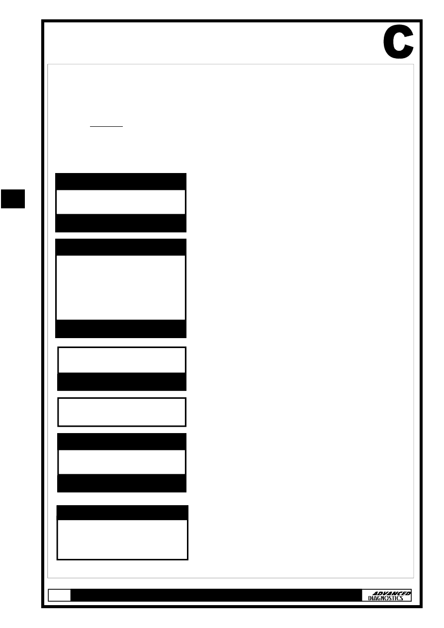
SYSTEM DESCRIPTIONS
Introduction
An immobiliser system was fitted as standard equipment on this
range of Honda vehicles, which prevents the vehicle from starting
unless a programmed key is used. There are 4 types of immobiliser
system used, which vary slightly in operation.
The four systems consist of:-
Note: Type 2 immobiliser system covers 2 different versions (a & b).
The differences between version ‘a & b’ are not apparent to the tech-
nician, however the correct application must be selected from the
‘Vehicle selection’ menu.
Where ‘Type 2’ is referred to within this manual, it is applicable to
both versions (a & b), unless otherwise stated.
System Keys - (All types)
Both master and valet keys are programmed keys, which means
they have a transponder embedded in their grips that provides an ID
(identification) code when inserted in the ignition switch. This ID
code is used by the immobiliser system to determine whether to
start the engine.
Note: The master key is also referred to as the original key.
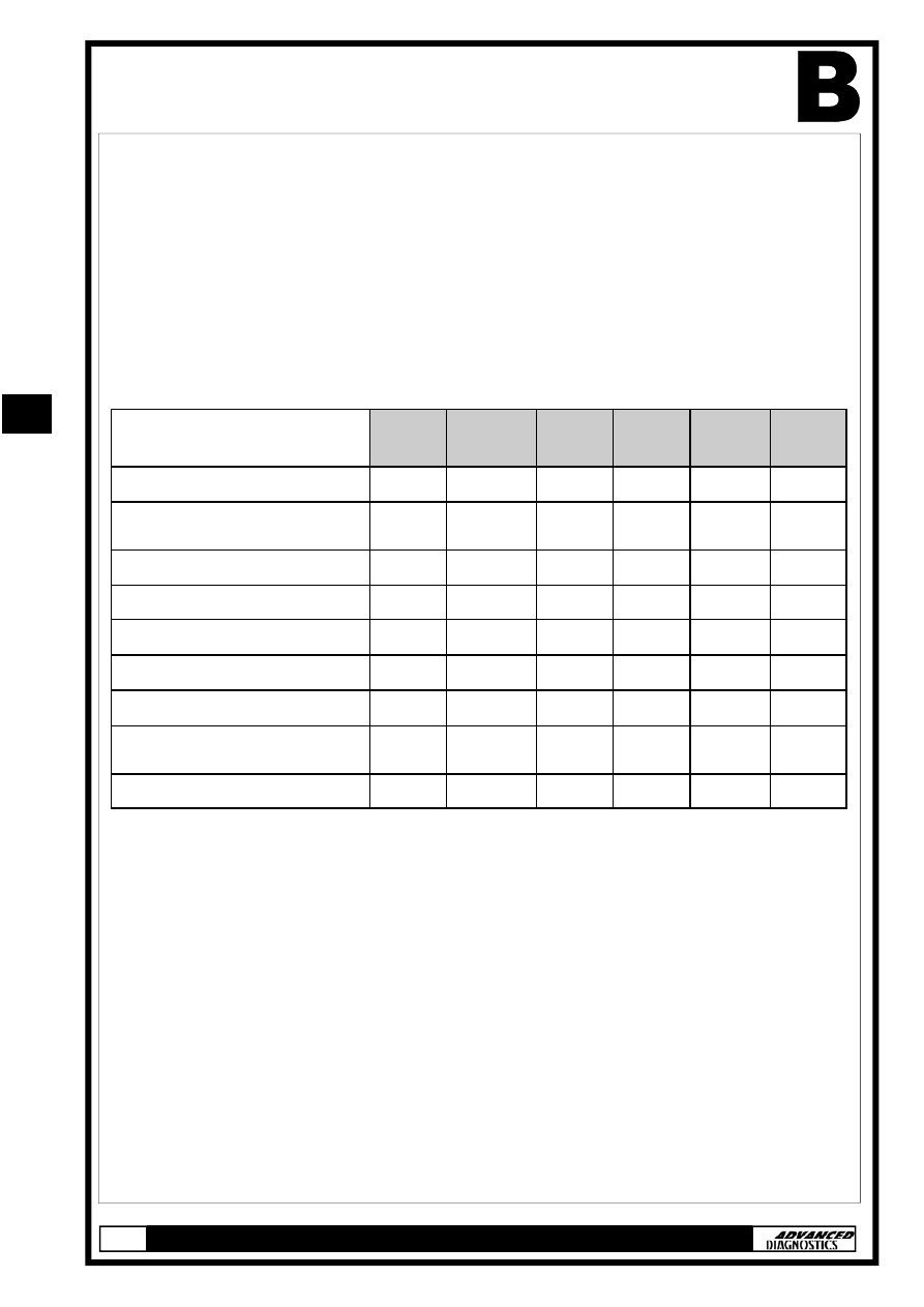
TYPE 1
(a & b)
TYPE 2
(a,b & c)
TYPE 3 TYPE 4
Immobiliser Keys
Master (Original) Key (2 off) -
Programmed
9
9
9
9
Valet Key (1 off) - Programmed
9
9
9
9
Learning Key (1 off)
9
-
-
-
Immobiliser System Indicator
9
9
9
9
Immobiliser Receiver
9
9
-
-
Immobiliser Control Unit
9
-
-
-
Immobiliser Control Unit-
Receiver
-
-
9
9
Electronic Control Unit (ECU)
9
9
9
9
TYPE 5
9
9
9
9
9
9
-
9
TYPE 6
9
9
9
9
9
9
-
9
11
11
GENERAL OPERATION
Type 1
In addition to the master and valet keys this system includes a
learning key which has a unique ID code that is matched to a par-
ticular vehicle’s immobiliser control unit. It allows the immobiliser
control unit to be re-programmed to either add additional pro-
grammed keys and/or delete ID codes of lost keys.
Important Note: The learning key will not start the engine
and may damage the immobiliser control unit if attempted.
Type 4
Unlike the other master and valet keys, those used on type 4 immo-
biliser system contain electronic circuitry that produce a ‘rolling-type’
code (determined by the control unit-receiver) when the key is in-
serted into the ignition switch. On LX and EX vehicle models the
master keys also include a battery operated remote transmitter al-
lowing the vehicle to be locked/unlocked. Both master and valet keys
are sidewinder-type and can be identified by a ‘V’ stamped on the
shank.
Immobiliser System Indicator - (All Types)
The immobiliser system indicator is a ‘key’ symbol that is located on
the instrument panel, whose location varies dependant on vehicle.
The ‘key’ symbol will illuminate when an ignition key is inserted, as
follows:
Key Type
Ignition Key
Position
Indicator Lamp
Programmed key
(Master or Valet)
Turn to ON (II)
Illuminates for 2 seconds
Turn to LOCK (0) &
remove key
Flashes for 5 seconds & goes off
Non-
Programmed Key
Turn to ON (II)
Illuminates for 2 seconds & then flashes. It
will continue to flash until the key is
removed.
Note:
TYPE 1 The engine will not crank.
TYPE 2,3,4 Engine Cranks but will not start.
11
11
GENERAL OPERATION
Immobiliser Receiver - (Type 1 & 2)
The receiver is an electrical coil embedded within the ignition switch
bezel. Power is provided by the immobiliser control unit (Type 1) or
the ECU (Type 2) and when a programmed key is inserted into the
ignition switch the transponder is energised by electromagnetic
induction. Once energised the transponder transmits its ID code to
the receiver, which is then transmitted to the control unit (Type 1) or
the ECM (Type 2).
Note: The immobiliser receiver does not need re-
programming when replaced.
Immobiliser Control Unit - (Type 1)
Location: Below the dashboard on the left side of the steering col-
umn.
Once the transponder ID code is received from the immobiliser re-
ceiver, it is checked against codes stored within its memory
(maximum of 5).
Code Accepted:
Power provided to the starter cut relay.
A unique serial code is transmitted to the
ECU
Code Not Accepted: No Power is provided to the starter cut relay
Unique
serial
code
is not transmitted to the
ECU.
Immobiliser Control Unit-Receiver - (Type 3 & 4)
These types of system use a combined immobiliser control unit-
receiver, which is located around the ignition switch. When a pro-
grammed key is inserted into the ignition switch the transponder is
energised by electromagnetic induction and transmits its ID code to
the control unit-receiver, where it is checked against codes stored
within its memory (maximum of 5).
Code Accepted:
A unique serial code is transmitted to the ECU.
Code Not Accepted: Unique serial code is not transmitted to the ECU.
11
11

GENERAL OPERATION
Engine Control Module (ECU) - (All types)
Type 1,3 & 4
When the ECU receives the unique serial code, it communicates back
to the immobiliser control unit by transmitting back its own unique
serial code. If both unique codes are mutually accepted, the ECU en-
ergises both the fuel supply and ignition system, thus allowing the
engine to start.
Type 2
This type of system receives the transponder ID code directly from
the immobiliser receiver and checks it against codes stored within its
memory (maximum of 5).
Code Accepted:
Fuel system energised, engine starts.
Code Not Accepted:
Fuel system not energised, engine will
not start.
11
11
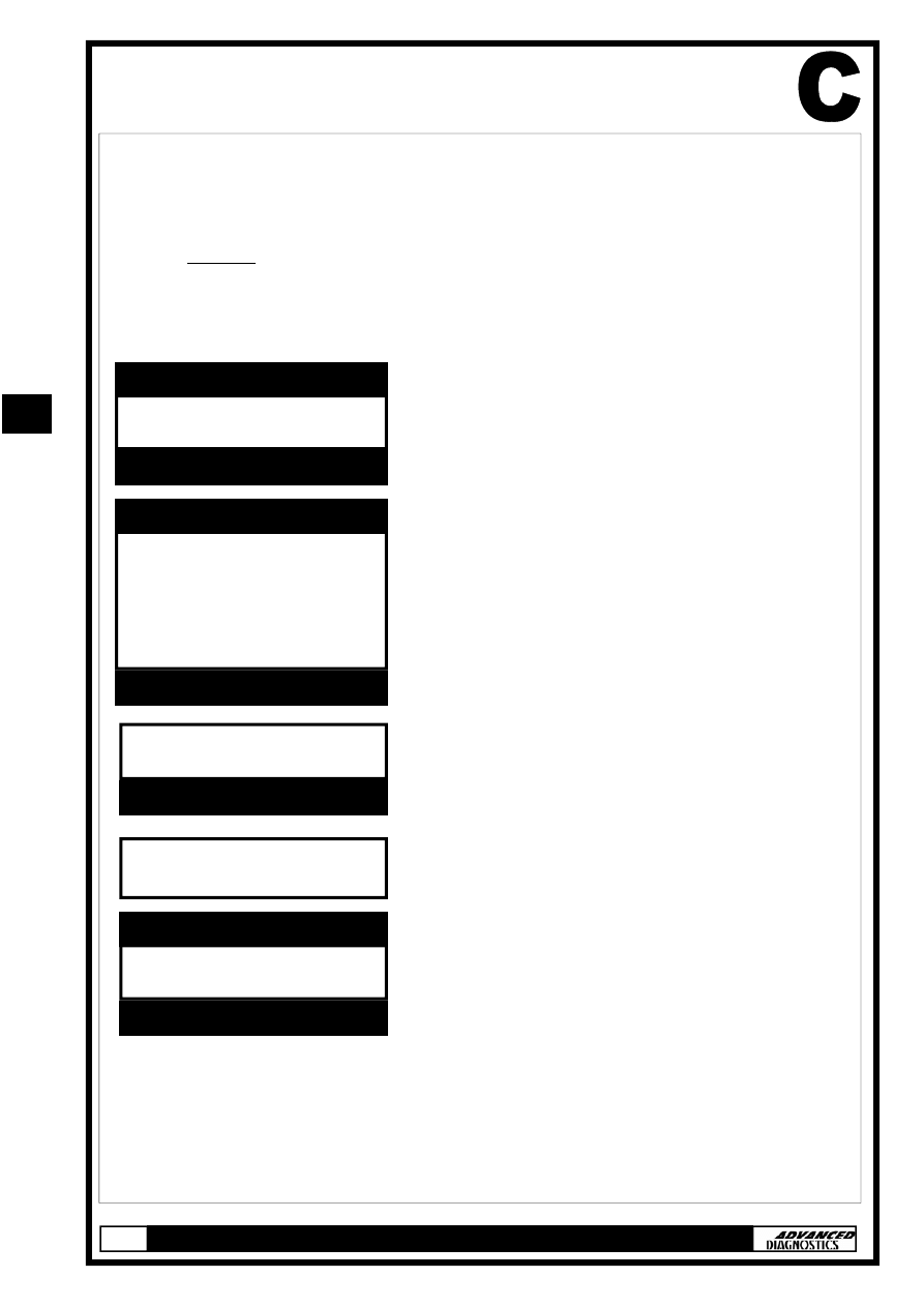
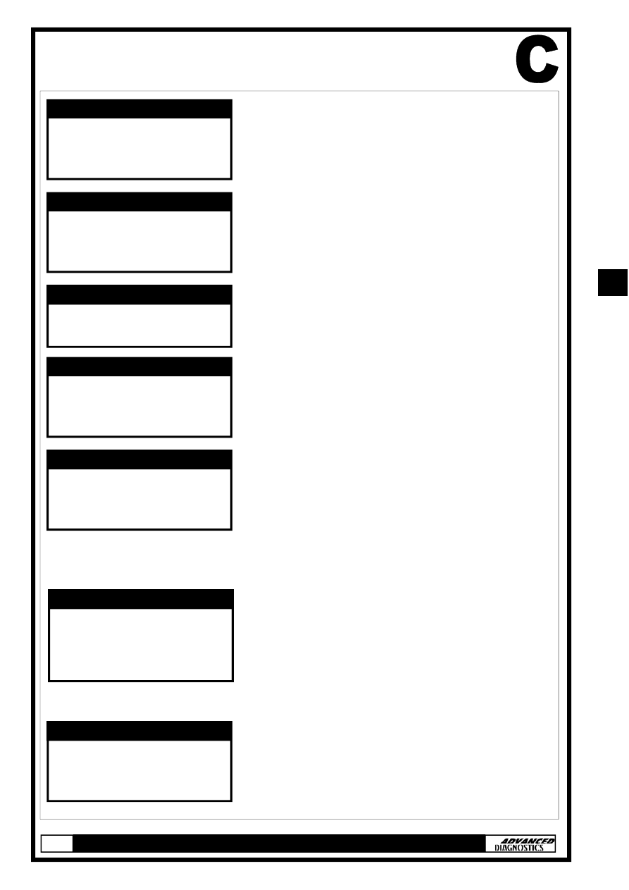
SPECIAL FUNCTIONS
TYPE 1 IMMOBILISER SYSTEM
The following procedure is used for:
•
Programming additional keys
Note: If all keys, master key or learning key are lost then a
replacement immobiliser control unit set is required.
•
Rewriting/Replacing Immobiliser control unit
•
Matching the Immobiliser control unit and ECU.
HONDA
VEHICLE SELECTION MENU
PRESS ENTER KEY
TURN IGNITION ON
PRESS ENTER KEY
PLEASE WAIT
TRYING TO COMMUNICATE
HONDA IMMO. USA-1
ECU IDENTIFICATION
PRESS ENTER KEY
TYPE 1
TYPE 2A
TYPE 2B
TYPE 3
TYPE 4
VEHICLE SELECTION MENU
PRESS ENTER KEY
At the VEHICLE SELECTION menu se-
lect the required vehicle and press the
ENTER key.
Select the immobiliser system type
from the application list and press the
ENTER key.
Turn Ignition ON and press the ENTER
key.
The TESTER will now attempt to com-
municate with the ECU.
If communication is successful the sys-
tem information will be displayed as
shown.
Press the ENTER key.
11
11
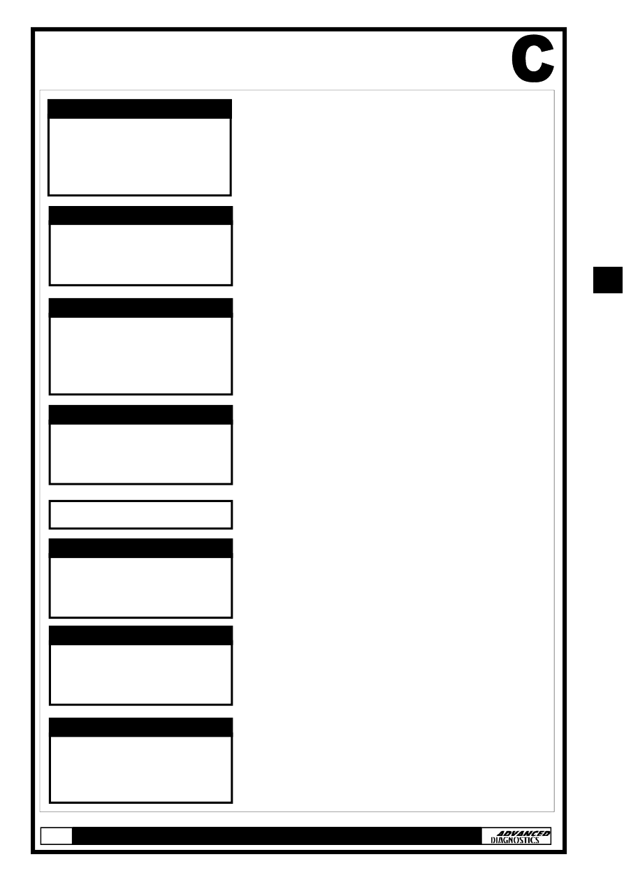
SPECIAL FUNCTIONS
Select SPECIAL FUNCTIONS and press
the ENTER key.
Select PROGRAM KEYS and press the
ENTER key.
Enter number of original (master) keys
NOTE : Please use RED learning key
supplied with IMMO box as one original
key.
Enter number of new keys to be pro-
grammed and press ENTER.
Note: Enter ‘0’ to either rewrite/
replace the immobiliser control unit
or match the ECM without program-
ming any additional keys.
ECU
IDENTIFICATION
SPECIAL FUNCTIONS
DIAGNOSTIC MENU
PROGRAM KEYS
KEY
INFORMATION
DIAGNOSTIC MENU
NO OF ORIGINAL KEYS:
INCLUDE RED
LEARNING KEY
REWRITE IMMOBILISER
NUMBER OF NEW KEYS:
REWRITE IMMOBILISER
SWITCH IGNITION OFF
SWITCH IGNITION ON WITH
RED KEY
PROGRAM KEYS
SWITCH IGNITION OFF
WITHIN 17 SEC
RED KEY
PROGRAM KEYS
SWITCH IGNITION ON
WITHIN 20 SEC
WITH ORIGINAL KEY
PROGRAM KEYS
11
11
SPECIAL FUNCTIONS
IF PROGRAMMING ADDITIONAL KEYS
FOLLOW STEPS A & B
STEP A
STEP B
SWITCH IGNITION OFF
WITHIN 17 SEC
ORIGINAL KEY
PROGRAM KEYS
SWITCH IGNITION ON
WITH NEW KEY
WITHIN 20 SEC
PROGRAM KEYS
SWITCH IGNITION OFF
WITHIN 17 SEC
RED KEY
PROGRAM KEYS
If you entered more than ‘0’ when
prompted to ‘enter number of new keys’
you will be asked to perform steps A &
B.
Steps A & B will be repeated for the
number of new keys that are being pro-
grammed.
Remember to use each new key when
prompted.
Check immobiliser light on the instru-
ment panel. Select ‘YES or NO’ and
press ENTER.
Entering ‘NO’ will direct you back to the
DIAGNOSTIC MENU.
SWITCH IGNITION ON
WITHIN 20 SEC
WITH RED KEY
PROGRAM KEYS
WAIT FOR 10 SEC
IS IMMO. LIGHT OUT
1. YES
2. NO
SWITCH IGNITION OFF
SWITCH IGNITION ON
WITH ORIGINAL KEY
SWITCH IGNITION OFF
11
11
SPECIAL FUNCTIONS
PROGRAMMING ADDITIONAL KEYS
FOLLOW STEPS C & D
STEP C
STEP D
SWITCH IGNITION ON
WITH NEW KEY
SWITCH IGNITION OFF
If you entered more than ‘0’ when
prompted to ‘enter number of new
keys’ you will be asked to perform
steps C & D.
Steps C & D will be repeated for the
number of new keys that are being
programmed.
Remember to use each new key when
prompted.
Procedure Complete
SWITCH IGNITION ON
WITH ORIGINAL KEY
SWITCH IGNITION OFF
SWITCH IGNITION ON
WITH ORIGINAL KEY
ECU
IDENTIFICATION
SPECIAL FUNCTIONS
DIAGNOSTIC MENU
11
11
SPECIAL FUNCTIONS
TYPE 2 (a & b), 3 & 4 IMMOBILISER SYSTEMS
The following procedure is used for:
•
Programming additional keys
Note: If all keys, master key or learning key are lost then a
replacement immobiliser control unit set is required.
•
Rewriting/Replacing Immobiliser control unit
•
Matching the Immobiliser control unit and ECU.
HONDA
VEHICLE SELECTION MENU
PRESS ENTER KEY
TURN IGNITION ON
PRESS ENTER KEY
PLEASE WAIT
TRYING TO COMMUNICATE
HONDA IMMO. USA-??
ECU IDENTIFICATION
PRESS ENTER KEY
TYPE 1
TYPE 2A
TYPE 2B
TYPE 3
TYPE 4
VEHICLE SELECTION MENU
PRESS ENTER KEY
At the VEHICLE SELECTION menu select
the required vehicle and press the
ENTER key.
Select the immobiliser system type from
the application list and press the ENTER
key.
Turn Ignition ON and press the ENTER
key.
The TESTER will now attempt to com-
municate with the ECU.
If communication is successful the sys-
tem information will be displayed as
shown. Press the ENTER key.
Note: ECU Identification will be either
USA-2a, 2b, 3 or 4.
Select SPECIAL FUNCTIONS and press
the ENTER key.
ECU
IDENTIFICATION
SPECIAL FUNCTIONS
DIAGNOSTIC MENU
11
11
SPECIAL FUNCTIONS
PROGRAMMING ADDITIONAL KEYS
FOLLOW STEPS A & B
STEP A
STEP B
Select PROGRAM KEYS and press the
ENTER key.
Enter number of new keys to be pro-
grammed and press ENTER.
Note: Enter ‘0’ to either rewrite/
replace the immobiliser control unit
or match the ECM without program-
ming any additional keys.
If you entered more than ‘0’ when
prompted ‘TOTAL KEYS REQUIRED’ you
will be asked to perform steps A & B.
Steps A & B will be repeated for the
number of new keys that are being pro-
grammed.
Remember to use each new key when
prompted.
PROGRAM KEYS
KEY
INFORMATION
DIAGNOSTIC MENU
TOTAL KEYS REQUIRED:
PROGRAM KEYS
SWITCH IGNITION OFF
PROGRAM KEYS
SWITCH IGNITION ON
WITH SAME KEY
PROGRAM KEYS
SWITCH IGNITION OFF
WITHIN 17 SEC
PROGRAM KEYS
SWITCH IGNITION ON
WITHIN 20 SEC
WITH NEXT KEY
PROGRAM KEYS
SWITCH IGNITION OFF
WITHIN 17 SEC
PROGRAM KEYS
11
11
SPECIAL FUNCTIONS
SWITCH IGNITION ON
WITH SAME KEY
WITHIN 17 SEC
PROGRAM KEYS
WAIT FOR 10 SEC
IS IMMO. LIGHT OUT
1. YES
2. NO
SWITCH IGNITION OFF
Check immobiliser light on the instru-
ment panel. Select ‘YES or NO’ and
press ENTER.
Entering ‘NO’ will direct you back to the
‘DIAGNOSTIC MENU’.
Procedure Complete
System: 1 indicates immobiliser system
ok.
Keys Stored: Indicates number of keys
programmed.
Type: 1, 2 or 3 dependant on
transponder.
SWITCH IGNITION ON
SYSTEM: 1
KEYS STORED: ??
TYPE: ??
KEY INFORMATION
11
11
TIPS & HINTS
1. The procedure for coding keys on the TESTER is merely a text
walkthrough (wait 17 secs, turn key off etc) it is completely un-
affected by the transponder type or indeed whether a trans-
ponder is fitted in the key or not. This is the reason for the im-
mobiliser light continuing to flash after the keys have been pro-
grammed. The question "is the warning light off" during the pro-
gramming procedure is a response to procedure rather than an
actual consequence of correct programming.
2. Honda vehicles have inertia switches fitted, these are a common
cause of non start on certain vehicles.
3. If the key receiver aerial is replaced, the TESTER will not pro-
gram in the keys. ECU coding will be required to match the Ae-
rial with the Engine Management ECU.
4. Civic vehicles with alarms will need to have the alarm turned off
prior to programming keys.
5. An immobiliser warning light that goes out during the program-
ming procedure (and is out when the TESTER asks “is the warn-
ing light off”) but comes back on after programming is an indica-
tion of an incorrect or faulty transponder.
11
11
REMOTE CONTROL PROGRAMMING
Programming of Infra Red remote controls.
NOTE : Maximum of 3 can be programmed.
NOTE : Please ensure time delays are maintained, otherwise procedure will not be completed correctly.
Procedure
1.
Turn ignition ON.
2.
Within 4 seconds push the transmitter button aiming the transmitter at the receiver unit above the
rear view mirror.
3.
Within 4 second turn ignition OFF.
4.
For additional remote controls repeat steps 1 to 4 within 4 seconds of programming the last remote
control.
5.
Turn ignition ON.
6.
Within 4 seconds push the transmitter button aiming the transmitter at the receiver unit above the
rear view mirror.
7.
The door actuator should operate.
8.
Within 8 seconds aim the first remote control at the receiver and press the transmitter button.
9.
The door actuator should operate.
10. Within 8 seconds aim the second remote control at the receiver and press the transmitter button.
11. The door actuator should operate.
12. Within 8 seconds aim the third remote control at the receiver and press the transmitter button.
13. Turn ignition OFF, and remove key.
14.
Confirm all remote controls operate.
11
11
11
11
Wyszukiwarka
Podobne podstrony:
Honda Manual
Honda NSR125 '87 Service Manual
HONDA Keyless Entry System Owner's Manual
HONDA Ridgeline Rear Camera System Owner's Manual
HONDA Pilot Backup Sensors User's Information Manual
HONDA Odyssey Security System Owner's Manual
manual honda vfr 800
Honda GB500 Manual
HONDA 2006 2007 Ridgeline Tonneau cover User's Information
PANsound manual
als manual RZ5IUSXZX237ENPGWFIN Nieznany
hplj 5p 6p service manual vhnlwmi5rxab6ao6bivsrdhllvztpnnomgxi2ma vhnlwmi5rxab6ao6bivsrdhllvztpnnomg
BSAVA Manual of Rabbit Surgery Dentistry and Imaging
Okidata Okipage 14e Parts Manual
Bmw 01 94 Business Mid Radio Owners Manual
więcej podobnych podstron