
Audel
™
HVAC Fundamentals
Volume 3
Air-Conditioning, Heat
Pumps, and Distribution
Systems
All New 4
th
Edition
James E. Brumbaugh
GK030-PFM[i-xx].qxd 7/2/04 11:48 PM Page i Quark03 Quark03:Desktop Folder:GK030-Brumbaugh-7-3.p

Vice President and Executive Group Publisher: Richard Swadley
Vice President and Executive Publisher: Robert Ipsen
Vice President and Publisher: Joseph B. Wikert
Executive Editor: Carol A. Long
Acquisitions Editor: Katie Feltman, Katie Mohr
Editorial Manager: Kathryn A. Malm
Development Editor: Kenyon Brown
Production Editor: Vincent Kunkemueller
Text Design & Composition: TechBooks
Copyright © 2004 by Wiley Publishing, Inc. All rights reserved.
Published simultaneously in Canada
No part of this publication may be reproduced, stored in a retrieval system, or
transmitted in any form or by any means, electronic, mechanical, photocopying,
recording, scanning, or otherwise, except as permitted under Section 107 or 108 of
the 1976 United States Copyright Act, without either the prior written permission
of the Publisher, or authorization through payment of the appropriate per-copy fee
to the Copyright Clearance Center, Inc., 222 Rosewood Drive, Danvers, MA
01923, (978) 750-8400, fax (978) 646-8700. Requests to the Publisher for permis-
sion should be addressed to the Legal Department, Wiley Publishing, Inc., 10475
Crosspoint Blvd., Indianapolis, IN 46256, (317) 572-3447, fax (317) 572-4447,
E-mail: permcoordinator@wiley.com.
Limit of Liability/Disclaimer of Warranty: The publisher and the author make no
representations or warranties with respect to the accuracy or completeness of the
contents of this work and specifically disclaim all warranties, including without lim-
itation warranties of fitness for a particular purpose. No warranty may be created or
extended by sales or promotional materials. The advice and strategies contained
herein may not be suitable for every situation. This work is sold with the under-
standing that the publisher is not engaged in rendering legal, accounting, or other
professional services. If professional assistance is required, the services of a compe-
tent professional person should be sought. Neither the publisher nor the author shall
be liable for damages arising herefrom. The fact that an organization or Web site is
referred to in this work as a citation and/or a potential source of further information
does not mean that the author or the publisher endorses the information the organi-
zation or Web site may provide or recommendations it may make. Further, readers
should be aware that Internet Web sites listed in this work may have changed or dis-
appeared between when this work was written and when it is read.
For general information on our other products and services, please contact our
Customer Care Department within the United States at (800) 762-2974, outside the
United States at (317) 572-3993 or fax (317) 572-4002.
Trademarks: Wiley, the Wiley Publishing logo, Audel are trademarks or registered
trademarks of John Wiley & Sons, Inc., and/or its affiliates. All other trademarks are
the property of their respective owners. Wiley Publishing, Inc., is not associated with
any product or vendor mentioned in this book.
Wiley also publishes its books in a variety of electronic formats. Some content that
appears in print may not be available in electronic books.
Library of Congress Control Number:
Printed in the United States of America
10 9 8 7 6 5 4 3 2 1
GK030-PFM[i-xx].qxd
7/2/04
11:48
PM
Page
ii
Quark03
Quark03:Desktop
Folder:GK030-Brumbaugh-7-3.p
eISBN: 0-7645-7626-7

For Laura, my friend, my daughter.
GK030-PFM[i-xx].qxd
7/2/04
11:48
PM
Page
iii
Quark03
Quark03:Desktop
Folder:GK030-Brumbaugh-7-3.

GK030-PFM[i-xx].qxd 7/2/04 11:48 PM Page iv Quark03 Quark03:Desktop Folder:GK030-Brumbaugh-7-3.

v
Contents
Introduction
xvii
About the Author
xix
Chapter 1
Radiant Heating
1
Types of Radiant Panel Heating Systems
2
Floor Panel Systems
2
Ceiling Panel Systems
2
Wall Panel Systems
5
Hydronic Radiant Floor Heating
6
System Components
6
Designing a Hydronic Radiant Floor
Heating System
28
Coils and Coil Patterns
41
Installing a Hydronic Radiant Floor
Heating System
(PEX Tubing)
44
Servicing and Maintaining Hydronic
Radiant Floor Heating Systems
49
Troubleshooting Hydronic Floor Radiant
Heating Systems
49
Hydronic Radiant Heating Snow- and
Ice-Melting Systems
51
Electric Radiant Floor Heating
52
Installing Electric Heating Mats or Rolls
58
Installing Electric Cable
65
Servicing and Maintaining an Electric
Radiant Floor Heating System
67
Troubleshooting Electric Radiant Floor
Heating Systems
67
Cooling for Hydronic Radiant Floor
Systems 68
GK030-PFM[i-xx].qxd 7/2/04 11:48 PM Page v Quark03 Quark03:Desktop Folder:GK030-Brumbaugh-7-3.p

vi
Contents
Chapter 2
Radiators, Convectors,
and Unit Heaters
71
Radiators 72
Radiator Efficiency
74
Radiator Heat Output
77
Sizing Radiators
78
Installing Radiators
79
Radiator Valves
86
Radiator Piping Connections
92
Vents and Venting
93
Steam Traps
99
Troubleshooting Radiators
99
Convectors 100
Convector Piping Connections
101
Hydronic Fan Convectors
106
Troubleshooting Hydronic Fan
Convectors 106
Steam and Hot-Water Baseboard
Heaters 107
Construction Details
108
Integral Fin-and-Tube Baseboard Heaters
112
Installing Baseboard Units
113
Baseboard Heater Maintenance
119
Electric Baseboard Heaters
119
Installing Electric Baseboard Heaters
124
Kickspace Heaters
127
Floor and Window Recessed Heaters
129
Unit Heaters
130
Unit Heater Piping Connections
135
Unit Heater Controls
138
Gas-Fired Unit Heaters
140
Oil-Fired Unit Heaters
141
Chapter 3
Fireplaces, Stoves, and Chimneys
145
Fireplaces 145
Fireplace Location
145
Fireplace Dimensions
146
GK030-PFM[i-xx].qxd 7/2/04 11:48 PM Page vi Quark03 Quark03:Desktop Folder:GK030-Brumbaugh-7-3.

Contents
vii
Fireplace Construction Details
149
Firebox, Lintel, and Mantel
150
Fireplace Hearth
151
Ash Dump, Ashpit, and
Cleanout Door
152
Smoke Chamber
152
Fireplace Dampers
153
Modified Fireplaces
156
Freestanding Fireplaces
157
Rumford Fireplace
158
Chimney Draft
162
Chimney Construction Details
164
Chimney Flues and Chimney Liners
165
Smoke Pipe
167
Cleanout Trap
168
Chimney Downdraft
168
Prefabricated Metal Chimneys
169
Troubleshooting Fireplaces and
Chimneys 169
Stoves, Ranges, and Heaters
169
Installation Instructions
177
Operating Instructions
178
Chapter 4
Water Heaters
179
Types of Water Heaters
179
Direct-Fired Water Heaters
180
Automatic Storage Water Heaters
180
Multicoil Water Heaters
182
Multiflue Water Heaters
183
Instantaneous Water Heaters
184
Indirect Water Heaters
185
Quick-Recovery Heaters
189
Slow-Recovery Heaters
189
Heat Pump Water Heaters
190
Combination Water Heaters
191
Water Heater Construction Details
192
Water Storage Tanks
193
GK030-PFM[i-xx].qxd
7/2/04
11:48
PM
Page
vii
Quark03
Quark03:Desktop
Folder:GK030-Brumbaugh-7-3

viii
Contents
Tank Fittings
194
Dip Tubes
194
Anodes 197
Valves 197
Safety Relief Valves
197
Vacuum Relief Valve
206
Gas-Fired Water Heaters
209
Storage Capacity
209
Gas Burners
210
Automatic Controls on Gas-Fired
Water Heaters
210
Combination Gas Valve
221
Installation and Operation of
Gas-Fired Water Heaters
225
Hot-Water Circulating Methods
230
Building and Safety Code
Requirements 230
Lighting and Operating Instructions
231
Installation and Maintenance
Checklist 232
Troubleshooting Gas-Fired Water
Heaters 233
Oil-Fired Water Heaters
238
Electric Water Heaters
240
Troubleshooting Electric Water Heaters
242
Manual Water Heaters
245
Assembly and Installation of Manual
Water Heaters
246
Solar Water Heaters
246
Chapter 5
Heating Swimming Pools
249
Classifying Pool Heaters
251
Gas-Fired Pool Heaters
255
Oil-Fired Pool Heaters
259
Electric Pool Heaters
260
Heat-Exchanger Pool Heaters
263
Solar Pool Heaters
264
GK030-PFM[i-xx].qxd
7/2/04
11:48
PM
Page
viii
Quark03
Quark03:Desktop
Folder:GK030-Brumbaugh-7-3

Heat Pump Pool Heaters
267
Sizing Pool Heaters
267
The Surface-Area Method
270
The Time-Rise Method
271
Sizing Indoor Pool Heaters
271
Installing Pool Heaters
271
Pool Heater Repair and Maintenance
273
Troubleshooting Pool Heaters and
Equipment 274
Chapter 6
Ventilation Principles
281
The Motive Force
282
Inductive Action of the Wind
282
Induced Draft
285
Combined Force of Wind Effect
and Thermal Effect
285
Mechanical Ventilation
287
Air Ventilation Requirements
287
Roof Ventilators
289
Types of Roof Ventilators
289
Stationary-Head Ventilators
290
Revolving Ventilators
290
Turbine Ventilators
291
Ridge Ventilators
293
Siphonage Ventilators
294
Fan Ventilators
294
Components of a Roof Ventilator
295
Motive Force to Cause Air Circulation
296
Capacity of Ventilators
296
Design and Placement of Inlet Air
Openings 298
Fresh Air Requirements
299
Ventilator Bases
299
Angle Rings
302
Stiffener Angles
303
Prefabricated Roof Curbs
303
Ventilator Dampers
304
Contents
ix
GK030-PFM[i-xx].qxd
7/2/04
11:48
PM
Page
ix
Quark03
Quark03:Desktop
Folder:GK030-Brumbaugh-7-3.

x
Contents
Louver Dampers
305
Sliding Sleeve Dampers
306
Sliding Cone Dampers
306
Butterfly Dampers
306
Method of Calculating Number and
Size of Ventilators Required
307
Ventilator Calculation Examples
308
Air Leakage
309
Garage Ventilation
310
Ventilation of Kitchens
311
General Ventilation Rules
312
Chapter 7
Ventilation and Exhaust Fans
315
Codes and Standards
315
Definitions 315
Types of Fans
317
Furnace Blowers
319
Basic Fan Laws
319
Series and Parallel Fan Operation
321
Fan Performance Curves
322
General Ventilation
322
Determining CFM by the Air-Change
Method 323
Determining CFM by the Heat Removal
Method 325
Determining Air Intake
326
Screen Efficiency
326
Static Pressure
327
Local Ventilation
328
Exhaust-Hood Design
Recommendations 332
Fan Motors
333
Troubleshooting Fans
337
Fan Selection
341
Fan Installation
344
Fan Installation Checklist
344
Air Volume Control
347
GK030-PFM[i-xx].qxd 7/2/04 11:48 PM Page x Quark03 Quark03:Desktop Folder:GK030-Brumbaugh-7-3.p

Noise Control
347
Fan Applications
347
Attic Ventilating Fans
348
Exhaust Fans
355
Kitchen Exhaust Fans
355
Bathroom Exhaust Fans
356
Whole-House Ventilation
356
Chapter 8
Air-Conditioning
361
Properties of Air
362
Humidity 362
Temperature 365
Pressure 368
Compression and Cooling
370
Measuring the Physical Properties
of Air
372
Cleaning and Filtering the Air
374
Standards of Comfort
376
The Comfort Chart
377
Cooling Load Estimate Form
379
Indoor-Outdoor Design Conditions
383
Ventilation Requirements
384
Cooling a Structure
386
External Sources of Heat
386
Internal Sources of Heat
392
Calculating Infiltration and Ventilation
Heat Gain
394
Rule-of-Thumb Methods for Sizing
Air Conditioners
394
HVAC Contractor’s Cooling Load
Estimate 395
Using the ACCA Design Manuals
for Sizing Air-Conditioning Systems
396
Central Air-Conditioning
397
Cooling Methods
397
Central Air-Conditioning Applications
410
Room Air Conditioners
421
Contents
xi
GK030-PFM[i-xx].qxd
7/2/04
11:48
PM
Page
xi
Quark03
Quark03:Desktop
Folder:GK030-Brumbaugh-7-3.

xii
Contents
Chapter 9
Air-Conditioning Equipment
423
Mechanical Refrigeration Equipment
423
Compressors 424
Troubleshooting Compressors
430
Compressor Replacement
435
Electric Motors
435
Troubleshooting Electrical Motors
436
Gas Engines
437
Electrical Components
437
Troubleshooting Electrical Components
438
Condenser 439
Condenser Service and Maintenance
442
Troubleshooting Condensers
443
Receiver 443
Evaporator 447
Evaporator Service and Maintenance
447
Troubleshooting Evaporators
447
Refrigerants 448
Liquid Refrigerant Control Devices
449
Automatic Expansion Valves
449
Thermostatic Expansion Valves
450
Float Valves
453
Capillary Tubes
454
Refrigerant Piping
454
Refrigerant Piping Service and
Maintenance 455
Troubleshooting Refrigerant Piping
456
Filters and Dryers
457
Pressure-Limiting Controls
457
Water-Regulating Valves
458
Automatic Controls
459
System Troubleshooting
459
General Servicing and Maintenance
460
Regular Maintenance
463
Pumping Down
464
Purging 464
Evacuating the System
464
GK030-PFM[i-xx].qxd
7/2/04
11:48
PM
Page
xii
Quark03
Quark03:Desktop
Folder:GK030-Brumbaugh-7-3.

Contents
xiii
Charging 465
Silver-Brazing Repairs
467
Chapter 10 Heat Pumps
471
Heat Pump Operating Principles
471
Heating Cycle
471
Cooling Cycle
473
Defrost Cycle
473
Types of Heat Pumps
476
Air-Source Heat Pumps
476
Ground-Source Heat Pumps
481
Water-Source Heat Pumps
483
Other Types of Heat Pumps
485
Gas-Fired Heat Pumps
485
Dual-Fuel Heat Pump System
486
Dual-Source Heat Pumps
486
Ductless Heat Pumps
487
Heat Pump Performance and Efficiency
Ratings 487
Seasonal Energy Efficiency Ratio (SEER)
488
Heating Season Performance Factor
(HSPF) 488
Coefficiency of Performance (COP)
488
Energy Efficiency Rating (EER)
488
Energy Star Rating
488
Heat Pump System Components
488
Compressor 490
Indoor Coil and Blower
491
Outdoor Coil and Fan
491
Refrigerant Lines
491
Reversing Valve and Solenoid
491
Thermostatic Expansion Valve
493
Desuperheater 494
Control Box
494
Fan/Blower Motors
499
Heat Pump Defrost System
499
High-Pressure Switch
500
Low-Pressure Switch
501
GK030-PFM[i-xx].qxd
7/2/04
11:48
PM
Page
xiii
Quark03
Quark03:Desktop
Folder:GK030-Brumbaugh-7-3

xiv
Contents
Other Electric/Electronic Heat Pump
Controls and Connections
501
Accumulator 501
Room Thermostat
501
Service Valves and Gauge Ports
502
Gauge Manifold
503
Filter Dryer
503
Crankcase Heater
503
Muffler 505
Sizing Heat Pumps
505
Heat Pump Installation
Recommendations 507
Heat Pump Operating Instructions
510
Heating
510
Cooling
511
Heat Pump Service and Maintenance
511
Service and Maintenance Checklist
512
Adjusting Heat Pump Refrigerant Charge
513
Troubleshooting Heat Pumps
514
Troubleshooting Heat Pump
Compressors 517
Chapter 11 Humidifiers and Dehumidifiers
519
Humidifiers 521
Spray Humidifiers
522
Pan Humidifiers
523
Stationary-Pad Humidifiers
524
Steam Humidifiers
524
Bypass Humidifiers
525
Power Humidifiers
526
Automatic Controls
526
Installation Instructions
529
Service and Maintenance Suggestions
534
Troubleshooting Humidifiers
535
Dehumidifiers 537
Absorption Dehumidifiers
538
Spray Dehumidifiers
541
GK030-PFM[i-xx].qxd 7/2/04 11:48 PM Page xiv Quark03 Quark03:Desktop Folder:GK030-Brumbaugh-7-3

Contents
xv
Refrigeration Dehumidifiers
541
Automatic Controls
542
Installation Suggestions
542
Operating and Maintenance Suggestions
542
Troubleshooting Dehumidifiers
543
Chapter 12 Air Cleaners and Filters
547
Electronic Air Cleaners
547
Charged-Media Air Cleaners
549
Two-Stage Air Cleaners
553
Automatic Controls
554
Clogged-Filter Indicator
556
Performance Lights
557
Sail Switch
559
In-Place Water-Wash Controls
561
Cabinet-Model Control Panels
563
Installation Instructions
564
Electrical Wiring
564
Maintenance Instructions
565
Replacing Tungsten Ionizing Wires
568
Troubleshooting Electronic Air Cleaners 569
Air Washers
571
Air Filters
572
Dry Air Filters
574
Viscous Air Filters
574
Filter Installation and Maintenance
575
Appendix A Professional and Trade Associations
577
Appendix B Manufacturers
589
Appendix C HVAC/R Education, Training,
Certification, and Licensing
601
Appendix D Data Tables
605
Appendix E Psychrometric Charts
643
Index
647
GK030-PFM[i-xx].qxd 7/2/04 11:48 PM Page xv Quark03 Quark03:Desktop Folder:GK030-Brumbaugh-7-3

GK030-PFM[i-xx].qxd 7/2/04 11:48 PM Page xvi Quark03 Quark03:Desktop Folder:GK030-Brumbaugh-7-3

Introduction
The purpose of this series is to provide the layman with an introduc-
tion to the fundamentals of installing, servicing, troubleshooting,
and repairing the various types of equipment used in residential and
light-commercial heating, ventilating, and air conditioning (HVAC)
systems. Consequently, it was written not only for the HVAC tech-
nician and others with the required experience and skills to do this
type of work but also for the homeowner interested in maintaining
an efficient and trouble-free HVAC system. A special effort was
made to remain consistent with the terminology, definitions, and
practices of the various professional and trade associations involved
in the heating, ventilating, and air conditioning fields.
Volume 1 begins with a description of the principles of thermal
dynamics and ventilation, and proceeds from there to a general
description of the various heating systems used in residences and
light-commercial structures. Volume 2 contains descriptions of the
working principles of various types of equipment and other compo-
nents used in these systems. Following a similar format, Volume 3
includes detailed instructions for installing, servicing, and repairing
these different types of equipment and components.
The author wishes to acknowledge the cooperation of the many
organizations and manufacturers for their assistance in supplying
valuable data in the preparation of this series. Every effort was
made to give appropriate credit and courtesy lines for materials and
illustrations used in each volume.
Special thanks is due to Greg Gyorda and Paul Blanchard (Watts
Industries, Inc.), Christi Drum (Lennox Industries, Inc.), Dave
Cheswald and Keith Nelson (Yukon/Eagle), Bob Rathke (ITT Bell &
Gossett), John Spuller (ITT Hoffman Specialty), Matt Kleszezynski
(Hydrotherm), and Stephanie DePugh (Thermo Pride).
Last, but certainly not least, I would like to thank Katie Feltman,
Kathryn Malm, Carol Long, Ken Brown, and Vincent Kunkemueller,
my editors at John Wiley & Sons, whose constant support and
encouragement made this project possible.
James E. Brumbaugh
GK030-PFM[i-xx].qxd
7/2/04
11:48
PM
Page
xvii
Quark03
Quark03:Desktop
Folder:GK030-Brumbaugh-7-3

GK030-PFM[i-xx].qxd
7/2/04
11:48
PM
Page
xviii
Quark03
Quark03:Desktop
Folder:GK030-Brumbaugh-7-

About the Author
James E. Brumbaugh is a technical writer with many years of expe-
rience working in the HVAC and building construction industries.
He is the author of the Welders Guide, The Complete Roofing
Guide, and The Complete Siding Guide.
GK030-PFM[i-xx].qxd
7/2/04
11:48
PM
Page
xix
Quark03
Quark03:Desktop
Folder:GK030-Brumbaugh-7-3

GK030-PFM[i-xx].qxd 7/2/04 11:48 PM Page xx Quark03 Quark03:Desktop Folder:GK030-Brumbaugh-7-3.

Chapter 1
Radiant Heating
Heat is lost from the human body through radiation, convection,
and evaporation. Radiation heat loss represents the transfer of
energy by means of electromagnetic waves. The convection loss is
the heat carried away by the passage of air over the skin and cloth-
ing. The evaporation loss is the heat used up in converting moisture
on the surface of the skin into vapor.
Heat transfer, whether by convection or radiation, follows the
same physical laws in the radiant heating system as in any other;
that is, heat flows from the warmer to the cooler exposure at a rate
directly proportional to the existing temperature difference.
The natural tendency of warmed air to rise makes it apparent
that this induced air current movement is greater at the cooler floor
and exterior walls of the average heated enclosure than at its ceil-
ing. It is through absorption by these air currents that the radiant
panel releases the convection component of its heat transfer into
the room air.
The average body heat loss is approximately 400 Btu per hour;
total radiation and convection account for approximately 300 to
320 Btu of it. Because this is obviously the major portion, the prob-
lem of providing comfort is principally concerned with establishing
the proper balance between radiation and convection losses.
It is important to understand that bodily comfort is obtained in
radiant heating by maintaining a proper balance between radiation
and convection. Thus, if the air becomes cooler and accordingly the
amount of heat given off from the body by convection increases,
then the body can still adjust itself to a sense of comfort if the heat
given off from the body by radiation is decreased. The amount
given off from the body by radiation can be decreased by raising the
temperature of the surrounding surfaces, such as the walls, floor,
and ceiling. For comfort, the body demands that if the amount of
heat given off by convection increases, the heat given off by radia-
tion must decrease, and vice versa.
The principles involved in radiant heating exist in such common-
place sources of heat as the open fireplace, outdoor campfires, elec-
tric spot heaters, and similar devices. In each of these examples, no
attempt is made to heat the air or enclosing surfaces surrounding
the individual. In fact, the temperature of the air and surrounding
1
GK030-P01[001-070].qxd 7/3/04 3:04 AM Page 1 Quark03 Quark03:Desktop Folder:GK030-Brumbaugh-fi

2
Chapter 1
surfaces may be very low, but the radiant heat from the fireplace or
campfire will still produce a sensation of comfort (or even discom-
fort from excess heat) to those persons within range. This situation
can occur even though a conventional thermometer may indicate a
temperature well below freezing. Radiant heat rays do not percepti-
bly heat the atmosphere through which they pass. They move from
warm to colder surfaces where a portion of their heat is absorbed.
This chapter is primarily concerned with a description of radiant
panel heating, which can be defined as a form of radiant heating in
which large surfaces are used to radiate heat at relatively low tem-
peratures. The principal emphasis will be on hydronic and electric
radiant floor heating.
Types of Radiant Panel Heating Systems
Radiant panel heating systems use water-filled tubing or electric heat-
ing mats or rolls installed in the floors, walls, and ceilings to dis-
tribute the heat. Radiant floor heating is by far the most popular
installation method in residential and light-commercial construction.
Note
The word panel is used to indicate a complete system of tubing
loops in a single room or space in a structure. It may also be used
to indicate a premanufactured radiant floor heating panel.
Floor Panel Systems
Floor panels are usually easier to install than either ceiling or wall
panels. Using floor panels is the most effective method of eliminating
cold floors in slab construction. Another advantage of heating with
floor panels is that much of the radiated heat is delivered to the lower
portions of the walls. The principal disadvantage of using floor panels
is that furniture and other objects block portions of the heat emission.
Floor panels are recommended for living or working areas con-
structed directly on the ground, particularly one-story structures.
Partial ceiling or wall treatment may be used as a supplement wher-
ever large glass or door exposures are encountered. A typical floor
installation is shown in Figure 1-1.
Ceiling Panel Systems
The advantage of a ceiling panel is that its heat emissions are not
affected by drapes or furniture. As a result, the entire ceiling area
can be used as a heating panel. Ceiling panels are recommended for
rooms or space with 7-foot ceilings or higher. A ceiling panel
should never be installed in a room with a low ceiling (under 7 feet)
because it may produce an undesirable heating effect on the head.
GK030-P01[001-070].qxd 7/3/04 3:04 AM Page 2 Quark03 Quark03:Desktop Folder:GK030-Brumbaugh-fi
In multiple-story construction, the use of ceiling panels appears
to be more desirable from both the standpoint of physical comfort
and overall economy. The designed utilization of the upward heat
transmission from ceiling panels to the floor of the area immedi-
ately above will generally produce moderately tempered floors.
Supplementing this with automatically controlled ceiling panels
Radiant Heating
3
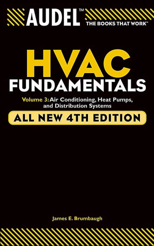
Figure 1-1
Diagram of a typical radiant floor heating installation.
FLOOR COVERING:
TILE, TERRAZZO
ASPHALT TILE, LINOLEUM
Concrete thickness to suit
architectural requirements.
Supply line feeds outer
panel edge first.
COARSE DRAINED GRAVEL
6" MIN THICKNESS
SOIL FILL
9" – 12"
3' – 0" MIN
2" – 4" BURY
W P INSUL
1
⁄
2
" MIN
1
1
⁄
2
" X TUBE SPACING
Area of panel extends beyond
last tube by
1
⁄
2
" tube spacing.
Balancing and shutoff
valves in floor box.
RETURN
SUPPLY
TUBE SIZE:
– = 9" SPACING
– 1" = 12" SPACING
1
1
⁄
2
" X TUBE
SPACING
1
⁄
2
"
3
⁄
4
"
3
⁄
4
"
GK030-P01[001-070].qxd 7/3/04 3:04 AM Page 3 Quark03 Quark03:Desktop Folder:GK030-Brumbaugh-fi
4
Chapter 1
will result in a very efficient radiant heating system. Except directly
below roofs or other unheated areas, this design eliminates the need
for the intermediate floor insulation sometimes used to restrict the
heat transfer from a ceiling panel exclusively to the area immedi-
ately below. It must be remembered, however, that when intermedi-
ate floor insulations are omitted, the space above a heated ceiling
will not be entirely independent with respect to temperature control
but will necessarily be influenced by the conditions in the space
below. A typical ceiling installation is shown in Figure 1-2.
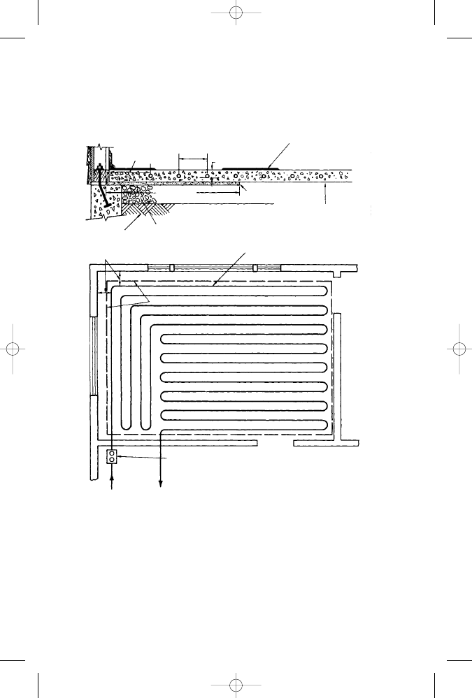
Figure 1-2
Diagram of a typical radiant ceiling heating panel.
HEATED ROOM ABOVE
Heat to room above equals
about 25% of output down.
METAL LATH OR
GYPSUM BOARD
PLASTER
1
⁄
4
" COVER
1
1
⁄
2
X TUBE SPACING
3
⁄
8
" NOMINAL
TUBE (
1
⁄
2
" O.D.)
4
1
⁄
2
"
TO 9"
INSULATION-6" ROCKWOOL
OR MORE
STANDARD
3
⁄
4
"
PLASTER
Supply line feeds
outer panel edge first.
NOTE:
At least 67% of
ceiling is covered
and unheated
section is on the
inside.
Area of panel extends
beyond last tube by
1
⁄
2
tube spacing.
In upfeed system raise
return to cross. Continue
up after crossing.
3
⁄
4
" RETURN
BALANCING
VALVES
SHUTOFF
3
⁄
4
"
SUPPLY
UNHEATED SPACE
GK030-P01[001-070].qxd 7/3/04 3:04 AM Page 4 Quark03 Quark03:Desktop Folder:GK030-Brumbaugh-fi
Apartment buildings and many office and commercial structures
should find the ceiling panel method of radiant heating most desir-
able. In offices and stores, the highly variable and changeable fur-
nishings, fixtures, and equipment favor the construction of ceiling
panels, to say nothing of the advantage of being able to make as
many partition alterations as desired without affecting the effi-
ciency of the heating system.
Wall Panel Systems
Walls are not often used for radiant heating because large sections
of the wall area are often interrupted by windows and doors.
Furthermore, the heat radiation from heating coils placed in the
lower sections of a wall will probably be blocked by furniture. As a
result, a radiant wall installation is generally used to supplement
ceiling or floor systems, not as a sole source of heat.
Wall heating coils are commonly used as supplementary heating
in bathrooms and in rooms in which there are a number of large
picture windows. In the latter case, the heating coils are installed in
the walls opposite the windows. Wall heating coils will probably
not be necessary if the room has good southern exposure. A typical
wall installation is shown in Figure 1-3.
Radiant Heating
5
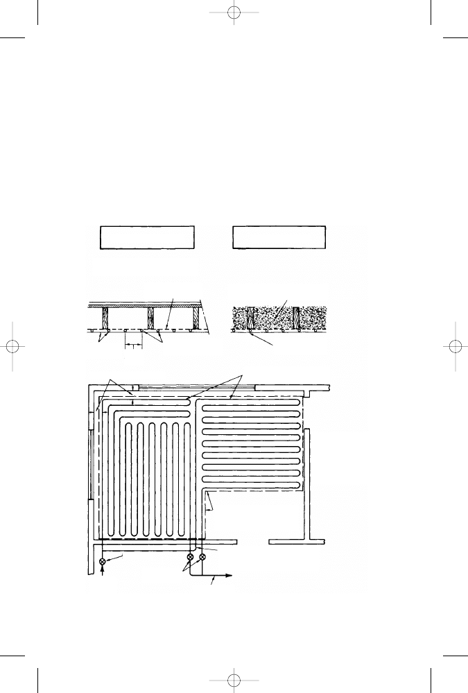
Figure 1-3
Typical wall installation. Panel is
installed on wall as high as possible.
BALANCING AND SHUTOFF
VALVES IN WALL BOX
DIRECTION OF FLOW
SAME AS MAINS
GK030-P01[001-070].qxd 7/3/04 3:04 AM Page 5 Quark03 Quark03:Desktop Folder:GK030-Brumbaugh-fi

6
Chapter 1
Hydronic Radiant Floor Heating
Hydronic radiant floor systems heat water in a boiler, heat pump,
or water heater and force it through tubing arranged in a pattern of
loops located beneath the floor surface. These systems can be clas-
sified as being either wet installations or dry installations depend-
ing on how the tubing is installed.
In wet installations, the tubing is commonly embedded in a con-
crete foundation slab or attached to a subfloor and covered with a
lightweight concrete slab. Dry installations are so called because the
tubing is not embedded in concrete.
System Components
The principal components of a typical hydronic radiant floor heat-
ing system can be divided into the following categories:
1.
Boilers, water heaters, and heat pumps
2.
Tubing and fittings
3.
Valves and related controls
4.
Circulator
5.
Expansion tank
6.
Air separator
7.
Heat exchanger
8.
Thermostat
Boilers, Water Heaters, and Heat Pumps
The boilers used in hot-water radiant heating systems are the
same types of heating appliances as those used in hydronic heat-
ing systems. Information about the installation, maintenance, ser-
vice, and repair of hydronic boilers is contained in Chapter 15 of
Volume 1.
Gas-fired boilers are the most widely used heat source in hydronic
radiant heating systems. Oil-fired boilers are second in popularity and
are used most commonly in the northern United States and Canada.
Coal-fired boilers are still found in some hydronic radiant heating
systems, but their use has steadily declined over the years.
Note
Hydronic radiant floor heating systems operate in an 85–140ºF
(29–60ºC) temperature range. This is much lower than the 130–
160ºF (54–71ºC) temperature operating range required in other
hydronic systems. As a result, the boilers used in floor systems
GK030-P01[001-070].qxd 7/3/04 3:04 AM Page 6 Quark03 Quark03:Desktop Folder:GK030-Brumbaugh-fi

operate at lower boiler temperatures, which results in a much
longer service life for the appliance.
The electric boilers used in hydronic radiant floor systems are
competitive with other fuels in those areas where electricity costs
are low. Their principal advantage is that they are compact appli-
ances that can be installed where space is limited.
Radiant floor systems can also be heated with a geothermal heat
pump. In climates where the heating and cooling loads are equal or
almost equal in size, a geothermal heat pump will be very cost effective.
Most standard water heaters produce a maximum of 40,000 to
50,000 Btu/h. This is sufficient Btu input to heat a small house or to
separately heat a room addition, but it cannot provide the heat
required for medium to large houses. As a result, some HVAC manu-
facturers have developed high-Btu-output dedicated water heaters for
radiant heating systems. These water heaters are designed specifically
as single heat sources for both the domestic hot water and the space-
heating requirements. As is the case with boilers used in hydronic
radiant heating systems, they operate in conjunction with a circulat-
ing pump and an expansion tank. See Chapter 4 (“Water Heaters”)
for additional information about combination water heaters.
Tubing and Fittings
The tubing in a radiant heating system is divided into the supply
and return lines. The supply line extends from the discharge open-
ing of a boiler to the manifold. It carries the heated fluid to the
loops (circuits) in the floors, walls, or ceilings. A return line extends
from the return side of a manifold to the boiler. It carries the water
from the heating panels back to the boiler where it is reheated.
Hydronic radiant floor heating systems use copper, plastic (PEX
or polybutylene tubing), or synthetic-rubber tubing to form the
loops. Because of space limitations, only the two most commonly
used types are described in this chapter: copper tubing and PEX
(plastic) tubing. Information about the other types of tubing used in
hydronic heating systems can be found in Chapter 8 (“Pipes, Pipe
Fittings, and Piping Details”) of Volume 2.
Loops or Circuits
The words loop and circuit are synonyms for the length of tubing within
a zone. Sometimes both are used in the same technical publication. At
other times, one or the other is used exclusively. Many loops or circuits
of the same length will form a zone. Circuits also refer to the electrical
circuit required to operate the heating system.
Radiant Heating
7
GK030-P01[001-070].qxd 7/3/04 3:04 AM Page 7 Quark03 Quark03:Desktop Folder:GK030-Brumbaugh-fi
8
Chapter 1
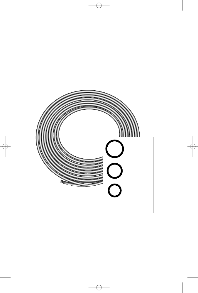
Copper Tubing
In most modern radiant floor heating systems, the water is circu-
lated through copper or cross-linked polyethylene (PEX) tubing
(see Figure 1-4). The metal coils used in hydronic radiant heating
systems commonly are made of copper tubing (both the hard and
soft varieties). Steel and wrought-iron pipe also have been used in
hydronic floor heating systems, but it is rare to find them in modern
residential radiant floor heating systems.
Figure 1-4
Copper tubing.
The soft tempered Type L copper tubing is recommended for
hydronic radiant heating panels. Because of the relative ease with
which soft copper tubes can be bent and shaped, they are especially
well adapted for making connections around furnaces, boilers, oil-
burning equipment, and other obstructions. This high workability
characteristic of copper tubing also results in reduced installation
3
⁄
4
-INCH ID
1
⁄
2
-INCH ID
3
⁄
8
-INCH ID
Inside diameters (ID) of commonly
used copper tubing in hydronic
radiant floor heating systems.
GK030-P01[001-070].qxd 7/3/04 3:04 AM Page 8 Quark03 Quark03:Desktop Folder:GK030-Brumbaugh-fi

time and lower installation costs. Copper tubing is produced in
diameters ranging from
1
⁄
8
inch to 10 inches and in a variety of dif-
ferent wall thicknesses. Both copper and brass fittings are available.
Hydronic heating systems use small tube sizes joined by soldering.
The size of the pipes or tubing used in these systems depends on
the flow rate of the water and the friction loss in the tubing. The
flow rate of the water is measured in gallons per minute (gpm), and
constant friction loss is expressed in thousandths of an inch for
each foot of pipe length. For a description of the various types of
tubing used in hydronic heating systems, see the appropriate sec-
tions of Chapter 8 (“Pipes, Pipe Fittings, and Piping Details”) in
Volume 2.
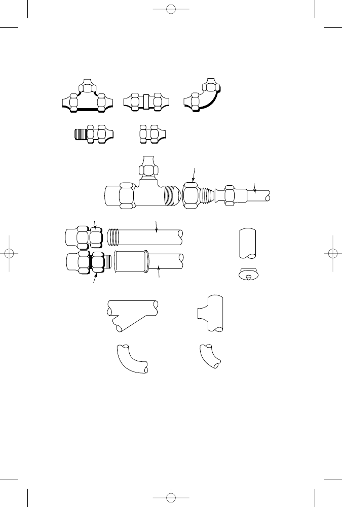
Most of the fittings used in hydronic radiant heating systems are
typical plumbing fittings. They include couplings (standard, slip,
and reducing couplings), elbows (both 45° and 90° elbows), male
and female adapters, unions, and tees (full size and reducing tees)
(see Figure 1-5).
Three special fittings used in hydronic radiant heating systems are
the brass adapters, the brass couplings, and the repair couplings. A
brass adapter is a fitting used to join the end of a length of
3
⁄
4
-inch
diameter copper tubing to the end of a length of plastic polyethylene
tubing. A brass coupling, on the other hand, is a fitting used to join
two pieces of plastic heat exchanger tubing. A repair coupling is a
brass fitting enclosed in clear vinyl protective sheath to prevent con-
crete from corroding the metal fitting. The fitting is strengthened by
double-clamping it with stainless steel hose clamps.
A decoiler bending device or jig should be used to bend metal
tubing into the desired coil pattern. Only soft copper tubing can be
easily bent by hand. It is recommended that a tube bender of this
type be made for each of the different center-to-center spacing
needed for the various panel coils in the installation.
Soft copper tubing is commonly available in coil lengths of 40
feet, 60 feet, and 100 feet. When the tubing is uncoiled, it should be
straightened in the trough of a straightener jig. For convenience of
handling, the straightener should not be more than 10 feet long.
Note
Most copper tubing leaks will occur at bends or U-turns in the floor
loops.These leaks are caused by water or fluids under high pressure
flowing through the weakened sections of tubing. The weakened
metal is commonly caused by improper bending techniques.
Whenever possible, continuous lengths of tubing should be used
with as few fitting connections as possible. Coils of 60 feet or 100 feet
Radiant Heating
9
GK030-P01[001-070].qxd 7/3/04 3:04 AM Page 9 Quark03 Quark03:Desktop Folder:GK030-Brumbaugh-fi
10
Chapter 1
are best for this purpose and are generally preferred for floor pan-
els. The spacing between the tubing should be uniform and
restricted to 12 inches or less. Use soldered joints to make connec-
tions between sections of tubing or pipe.
Figure 1-5
Some examples of copper tubing fittings.
T-FITTING
UNION
MALE ADAPTER
FEMALE ADAPTER
FEMALE ADAPTER
MALE ADAPTER
RIGID PIPE
END CAP
BRANCH FITTING
T-FITTING
90
° ELBOW
45
° ELBOW
RIGID PIPE
90
° ELBOW
REDUCER
COPPER
1
⁄
2
"
3
⁄
4
"
GK030-P01[001-070].qxd 7/3/04 3:04 AM Page 10 Quark03 Quark03:Desktop Folder:GK030-Brumbaugh-
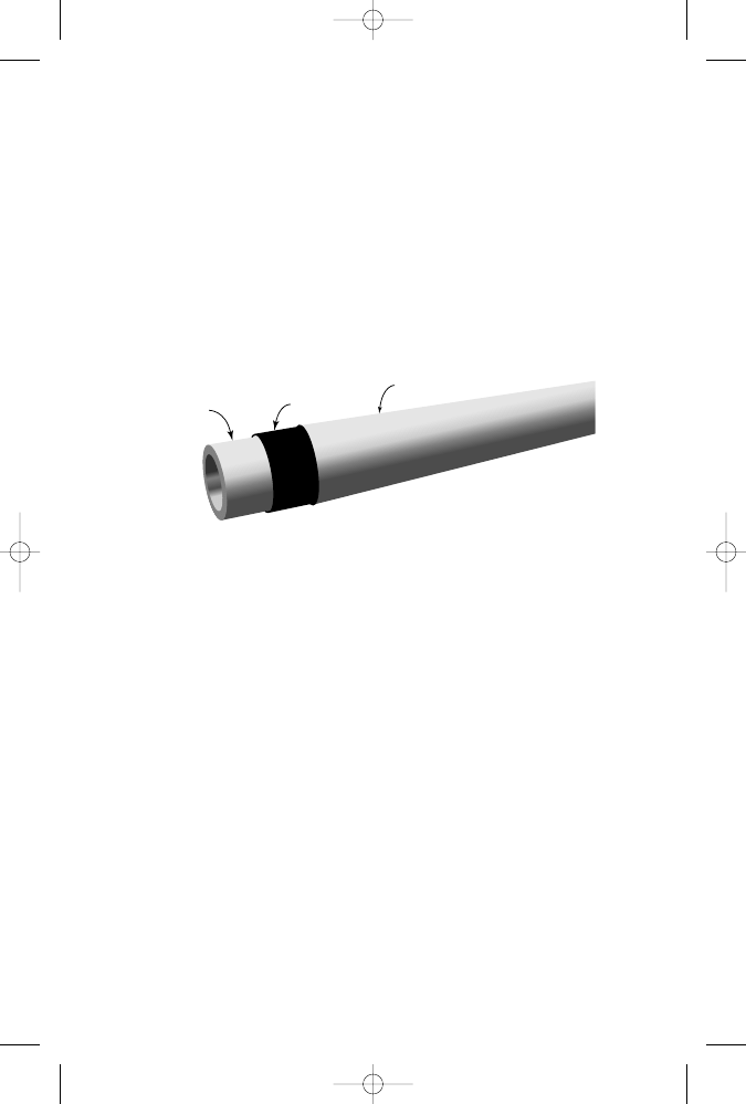
Cross-Linked Polyethylene (PEX) Tubing
Cross-linked polyethylene (PEX) tubing is commonly used indoors in
hydronic radiant heating panels or outdoors embedded beneath the
surface of driveways, sidewalks, and patios to melt snow and ice. It
is made of a high-density polyethylene plastic that has been subjected
to a cross-linking process (see Figures 1-6, 1-7, and 1-8). It is flexi-
ble, durable, and easy to install. There are two types of PEX tubing:
•
Oxygen barrier tubing
•
Nonbarrier tubing
Radiant Heating
11
Figure 1-6
PEX tubing.
(Courtesy Watts Radiant, Inc.)
Oxygen barrier tubing (BPEX) is treated with an oxygen barrier
coating to prevent oxygen from passing through the tubing wall
and contaminating the water in the system. It is designed specifi-
cally to prevent corrosion to any ferrous fittings or valves in the
piping system. BPEX tubing is recommended for use in a hydronic
radiant heating system.
Nonbarrier tubing should be used in a hydronic radiant heating
system only if it can be isolated from the ferrous components by a
corrosion-resistant heat exchanger, or if only corrosion-resistant
system components (boiler, valves, and fittings) are used.
PEX tubing is easy to install. Its flexibility allows the installer to
bend it around obstructions and into narrow spaces. A rigid plastic
cutter tool, or a copper tubing cutter equipped with a plastic cut-
ting wheel, should be used to cut and install PEX tubing. Both tools
produce a square cut without burrs.
PEX tubing can be returned to its original shape after accidental
crimping or kinking by heating it to about 250–275°F. This attribute
of PEX tubing makes it possible to perform field repairs without
removing the damaged tubing section. This is not the case with poly-
butylene tubing, which is not cross-linked. Synthetic rubber tubing
Radiant
PEX
CROSS-LINKED
POLYETHYLENE
ADHESIVE LAYER
EVOH OXYGEN BARRIER
GK030-P01[001-070].qxd 7/3/04 3:04 AM Page 11 Quark03 Quark03:Desktop Folder:GK030-Brumbaugh-
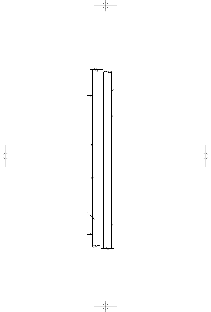
Figur
e 1-7
PEX tubing markings.
(Cour
tesy
Vanguard Piping Systems
,Inc
.)
V
ANGUARD V
ANEX
®
PEX PORT
ABLE TUBING
1
⁄
2
" (CTS-OD) 100 PSI @ 180F / 160 PSI @ 73F [ NSF-pw CL-R/CL-TD
MANUF
ACTURER
TRADE NAME
TUBING TYPE
TUBE SIZE
PRESSURE RA
TINGS
THIRD-P
ARTY
CERTIFICA
TION
ASTM F876 / F877 / F2023 ] CAN B 137.5 L23707 ICBO ES ER-5287 HUD MR 1276 SDR9 .070 DA
TE CO
DE
ASTM
SPECIFICA
TION
ST
ANDARD
DIMENSION RA
TIO
MANUF
ACTURER'S
DA
TE CODE
12
GK030-P01[001-070].qxd 7/3/04 3:04 AM Page 12 Quark03 Quark03:Desktop Folder:GK030-Brumbaugh-
Radiant Heating
13
Figure 1-8
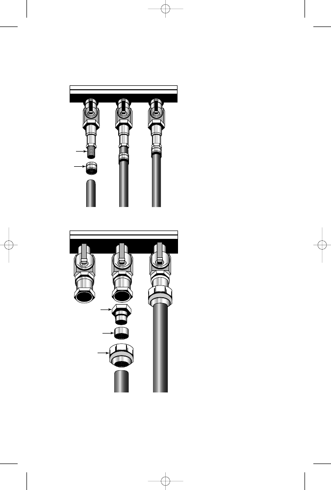
PEX tubing fittings.
(Courtesy Watts Radiant, Inc.)
1
2
3
Crimping Fittings
Compression Fitting
1.
2. Insert the brass fitting into the end of
the expanded PEX tube.
3. Use the expansion tool to pull the brass
sleeve back over the PEX tube and
fitting for a tight connection.
FITTING
SLEEVE
1
2
3
FITTING
RING
NUT
Expand the end of the PEX tubing with
the expansion tool provided by the
PEX tube manufacturer.
1. Slide the locking nut and split compres-
sion ring up the tubing.
2. Insert the tubing onto the compression
fitting.
3. Tighten the nut onto the compression
Re-tighten the fittings after the heat has
been turned on and the hot water has
circulated through the tubing.
4.
fitting snugly.
GK030-P01[001-070].qxd 7/3/04 3:04 AM Page 13 Quark03 Quark03:Desktop Folder:GK030-Brumbaugh-
14
Chapter 1
is also not cross-linked, but its material composition and its flexibility
make it very resistant to crimping or kinking damage.
Manifolds
A manifold is a device used to connect multiple tubing lines to a sin-
gle supply or return line in a hydronic radiant floor heating system
(see Figures 1-9 and 1-10). Each heating system has at least two
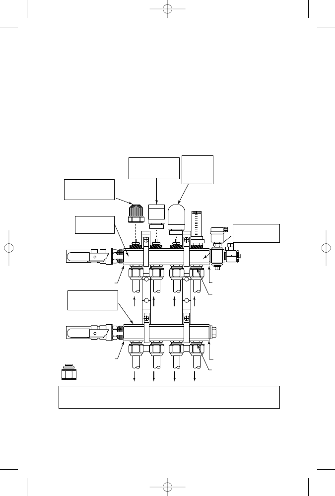
Figure 1-9
Weil-McLain hydronic radiant heating manifold.
(Courtesy Weil-McLain)
ELECTRIC
ACTUATOR WITHOUT
END SWITCH
RETURN MANIFOLD
WITH FLOW
INDICATOR VALVES
MANUAL VALVE
OPERATOR (INCL. W/
VALVED MANIFOLDS)
MANIFOLD WITHOUT
VALVES (USE AS
RETURN OR SUPPLY)
ELECTRIC
ACTUATOR
WITH END
SWITCH
MANIFOLD WITH
INTEGRAL
VALVES
BALL VALVES AND PIPING
BY OTHERS
BALL VALVES AND PIPING
BY OTHERS
THREADED 1" BSP
THREADED 1" BSP
OPTIONAL TAKEOFF CAPS TO
CAP OFF UNUSED TAKEOFFS
FLOW
FLOW
FLOW
FLOW
FLOW
FLOW
FLOW
FLOW
THREADED 1" BSP
TUBING CONNECTIONS
3
⁄
4
" EURO CONICAL
THREADED 1" BSP
TUBING CONNECTIONS
3
⁄
4
" EURO CONICAL
Flow indicators (when used)
require flow indicator
manifold, item 3.
SUPPLY
RETURN
Manifolds with integral valves should be used as return manifolds unless flow indicators are desired. If both flow
indication and electric valve actuators are needed, use manifold with flow indicator valves on their turn and
manifold with integral valves on the supply. Apply any desired combination of 2-wire and 4-wire electric actuators.
FLOW
FLOW
GK030-P01[001-070].qxd 7/3/04 3:04 AM Page 14 Quark03 Quark03:Desktop Folder:GK030-Brumbaugh-
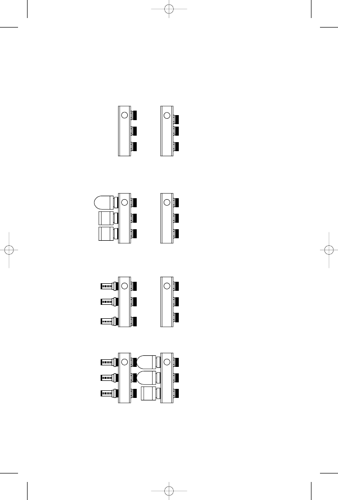
Figur
e 1-10
Manif
old combinations.
(Cour
tesy W
eil-McLain)
RETURN
3
1
SUPPLY
1
RETURN
3
2
RETURN: FLOW INDICATORS
SUPPLY: NO VALVES
RETURN: FLOW INDICATORS
SUPPLY: ELECTRIC VALVES
SUPPLY
1
RETURN: ELECTRIC VALVES
SUPPLY: NO VALVES
4
RETURN
1
SUPPLY
1
RETURN: NO VALVES
SUPPLY: NO VALVES
SUPPLY
2
3
RETURN
2
This combination allows
independent zone control
and easy balancing.
This combination provides
easy balancing, but does
not provide independent
zone control.
This combination provides
independent zone control.
Balancing will be more difficult
than combination 1 or 2.
This combination provides
no balancing means. Use
ball valves in tubing circuits
if balancing is needed.
15
GK030-P01[001-070].qxd 7/3/04 3:04 AM Page 15 Quark03 Quark03:Desktop Folder:GK030-Brumbaugh-
16
Chapter 1
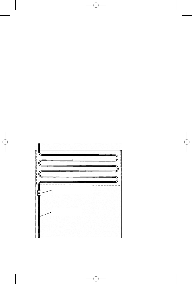
types of manifolds: a supply manifold and a return manifold. A sup-
ply manifold receives water from the heating appliance (that is, the
boiler, water heater, or heat pump) through a single supply pipe and
then distributes it through a number of different tubing lines to the
room or space being heated (see Figure 1-11). A return manifold
provides the opposite function. It receives the return water from the
room or space through as many tubing lines and sends it back to the
boiler by a single return pipe. A supply manifold and a return mani-
fold are sometimes referred to jointly as a manifold station.
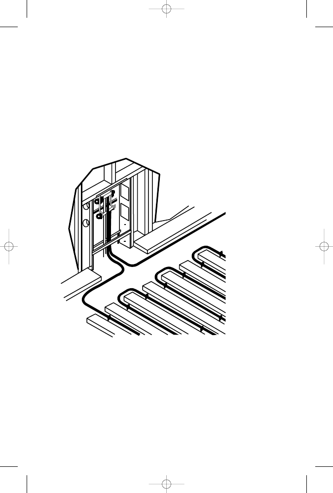
Figure 1-11
Typical manifold location.
Preassembled manifolds are available from manufacturers for
installation in most types of heating systems. Customized manifolds
can also be ordered, but they are more expensive than the standard,
preassembled types.
A supply manifold, when operating in conjunction with zone
valves, can be used to control the hot water flow to the distribution
lines in the radiant heating system. The zone valves, which are usu-
ally ball valves, can be manually adjusted or automatically opened
GK030-P01[001-070].qxd 7/3/04 3:04 AM Page 16 Quark03 Quark03:Desktop Folder:GK030-Brumbaugh-

and closed with a zone valve actuator. Some zone valves are designed
as fully open or fully closed valves. Others are operated by a modu-
lating actuator that can adjust the opening to the heat required by the
zoned space.
A supply manifold with zoning capabilities is sometimes called a
zone manifold or distribution manifold. In addition to zone valves,
these manifolds also can be ordered to include supply and return
water sensors, the circulator, and a control panel with indoor and
outdoor sensors.
Depending on the heating system requirements, a manifold may
also include inline thermometers or a temperature gauge to measure
the temperature of the water flowing through the tubing; check
valves or isolation valves to isolate the manifold so that it can be ser-
viced or repaired; drain valves to remove water from the manifold;
an air vent to purge air from the system; and pump flanges (for the
circulator) plus all the required plumbing connections and hardware.
Manifold balancing valves regulate each zone (loop) to ensure
efficient heat distribution and eliminate those annoying cold and
hot spots on the floor. These valves can be adjusted to deliver the
design flow rate of water in gallons per minute (gpm). Some mani-
folds are designed to electronically read the flow and temperature
of the water in individual tubing loops. This function results in
rapid and accurate data feedback for balancing. It also makes trou-
bleshooting problems easier.
Manifolds are available for mounting on walls or installation in
concrete slabs. The latter type, sometimes called a slab manifold, is
made of copper and is available with up to six supply and six return
loop connections. Slab manifolds also should be equipped with a
pressure-testing feature so that they can be tested for leaks before
the slab is poured.
Slab manifolds are installed with a box or form that shields the
device from the concrete when it is poured. All connections remain
below the level of the floor except for the tops of the supply and
return tubing.
Valves and Related Control Devices
Valves and similar control devices are used for a variety of different
purposes in a hydronic radiant floor heating system. Some are used
as high-limit controls to prevent excessively hot water from flowing
through the floor loops. Some are used to isolate system compo-
nents, such as the circulating pump, so that it can be serviced or
removed without having to shut down the entire system. Others are
used to regulate the pressure or temperature of the water, to reduce
Radiant Heating
17
GK030-P01[001-070].qxd 7/3/04 3:04 AM Page 17 Quark03 Quark03:Desktop Folder:GK030-Brumbaugh-
18
Chapter 1
the pressure of the water before it enters the boiler, or to regulate
the flow of water.
Many of the different types of valves and control devices used in
hydraulic radiant floor heating systems are listed in the sidebar. A brief
description of the more commonly used ones is provided in this sec-
tion. For a fuller, more detailed description of their operation, mainte-
nance, service, and repair, read the appropriate sections of Chapter 9
(“Valves and Valve Installation”) of Volume 2. Not all the valves listed
in the sidebar or the ones described in this chapter will necessarily be
used in the same heating system. The valves chosen will fit the require-
ments of a specific application (see Figures 1-12, 1-13, and 1-14).
Hydraulic Heating System Valves and Related Control Devices
•
Air vent
•
Aquastat
•
Backflow preventers
•
Ball valves
•
Boiler drain valve
•
Check valves
•
Feed water pressure regulator
•
Flow control valve
•
Gate valve
•
Globe valve
•
Isolation valve
•
Mixing valve
•
Motorized zone valve
•
Pressure-reducing valve
•
Pressure relief valve
•
Purge and balancing valves
•
Solenoid valve
Air Vent
An air vent is a device used to manually or automatically expel air
from a closed hydronic heating system. An automatic air vent valve
provides automatic and continuous venting of air from the system.
The function of both types is to prevent air from collecting in the
piping loops.
GK030-P01[001-070].qxd 7/3/04 3:04 AM Page 18 Quark03 Quark03:Desktop Folder:GK030-Brumbaugh-
Aquastat
An aquastat is a control device consisting of a sensing bulb, a
diaphragm, and a switch (see Figure 1-14). As the temperature sur-
rounding the sensing bulb increases, the gas inside the bulb
expands and flows into the diaphragm. This action causes the
diaphragm to expand and activate the switch controlling the con-
nected device. When temperatures exceed the high-limit setting on
Radiant Heating
19
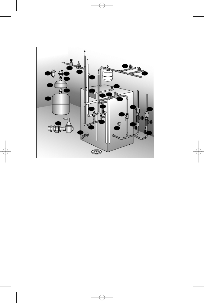
Figure 1-12
Typical locations of valves and related control
devices in a hydronic heating system.
(Courtesy Watts Regulator Co.)
16
1
6
4a
20
19
17
18
14
22
15
15
11
11
15
15
21
10
13
2
7
7
8
5
3
3. Boiler drain valve.
4. Boiler fill valve.
4a. Combination backflow preventer
and boiler fill valve.
5. Bronze check valve.
6. Expansion tank.
7. Flow check valves.
8. Flow control valve.
9. Gate or globe valve.
9
12
4
12. Pressure relief valve.
13. Hot water safety relief valve.
14. Test plug.
15. Ball valve.
16. Automatic float vent valve.
17. Float vent.
18. Water pressure reducing valve.
19. Service check valve.
20. Combination temperature
and pressure gauge.
21. Boiler energy saver.
11. Purge valve.
10. Mixing valve.
1. Air scoop.
2. Backflow preventer.
GK030-P01[001-070].qxd 7/3/04 3:04 AM Page 19 Quark03 Quark03:Desktop Folder:GK030-Brumbaugh-
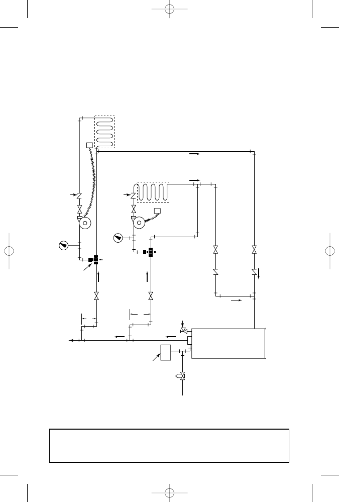
Figur
e 1-13
Piping diagram of a zoned radiant heating system suppl
ying hot water to both
floor panels and baseboar
ds.
TO
BASEBOARD
M
HC
M
HC
3-WAY
VALVE
3-WAY MIXING
VALVE
THERMOMETER
THERMOMETER
FLOW CONTROL
VALVE
FLOW CONTROL
VALVE
THERMOSTAT
THERMOSTAT
RADIANT
ZONE
RADIANT
ZONE
27" MIN
27" MIN
COMPRESSION
TANK
FILL
VALVE
RELIEF
VALVE
BOILER
GK030-P01[001-070].qxd 7/3/04 3:04 AM Page 20 Quark03 Quark03:Desktop Folder:GK030-Brumbaugh-
Document Outline
- Introduction
- About the Author
- Chapter 1: Radiant Heating
- Types of Radiant Panel Heating Systems
- Hydronic Radiant Floor Heating
- System Components
- Designing a Hydronic Radiant Floor Heating System
- Coils and Coil Patterns
- Installing a Hydronic Radiant Floor Heating System (PEX Tubing)
- Servicing and Maintaining Hydronic Radiant Floor Heating Systems
- Troubleshooting Hydronic Floor Radiant Heating Systems
- Hydronic Radiant Heating Snow- and Ice-Melting Systems
- Electric Radiant Floor Heating
- Installing Electric Heating Mats or Rolls
- Installing Electric Cable
- Servicing and Maintaining an Electric Radiant Floor Heating System
- Troubleshooting Electric Radiant Floor Heating Systems
- Cooling for Hydronic Radiant Floor Systems
- Chapter 2: Radiators, Convectors, and Unit Heaters
- Radiators
- Radiator Efficiency
- Radiator Heat Output
- Sizing Radiators
- Installing Radiators
- Radiator Valves
- Radiator Piping Connections
- Vents and Venting
- Steam Traps
- Troubleshooting Radiators
- Convectors
- Convector Piping Connections
- Hydronic Fan Convectors
- Troubleshooting Hydronic Fan Convectors
- Steam and Hot-Water Baseboard Heaters
- Construction Details
- Integral Fin-and-Tube Baseboard Heaters
- Installing Baseboard Units
- Baseboard Heater Maintenance
- Electric Baseboard Heaters
- Installing Electric Baseboard Heaters
- Kickspace Heaters
- Floor and Window Recessed Heaters
- Unit Heaters
- Unit Heater Piping Connections
- Unit Heater Controls
- Gas-Fired Unit Heaters
- Oil-Fired Unit Heaters
- Radiators
- Chapter 3: Fireplaces, Stoves, and Chimneys
- Fireplaces
- Fireplace Location
- Fireplace Dimensions
- Fireplace Construction Details
- Firebox, Lintel, and Mantel
- Fireplace Hearth
- Ash Dump, Ashpit, and Cleanout Door
- Smoke Chamber
- Fireplace Dampers
- Modified Fireplaces
- Freestanding Fireplaces
- Rumford Fireplace
- Chimney Draft
- Chimney Construction Details
- Chimney Cap
- Chimney Flues and Chimney Liners
- Smoke Pipe
- Cleanout Trap
- Chimney Downdraft
- Prefabricated Metal Chimneys
- Troubleshooting Fireplaces and Chimneys
- Stoves, Ranges, and Heaters
- Installation Instructions
- Operating Instructions
- Fireplaces
- Chapter 4: Water Heaters
- Types of Water Heaters
- Direct-Fired Water Heaters
- Automatic Storage Water Heaters
- Multicoil Water Heaters
- Multiflue Water Heaters
- Instantaneous Water Heaters
- Indirect Water Heaters
- Quick-Recovery Heaters
- Slow-Recovery Heaters
- Heat Pump Water Heaters
- Combination Water Heaters
- Water Heater Construction Details
- Water Storage Tanks
- Tank Fittings
- Dip Tubes
- Anodes
- Valves
- Safety Relief Valves
- Vacuum Relief Valve
- Gas-Fired Water Heaters
- Storage Capacity
- Gas Burners
- Automatic Controls on Gas-Fired Water Heaters
- Combination Gas Valve
- Installation and Operation of Gas-Fired Water Heaters
- Hot-Water Circulating Methods
- Building and Safety Code Requirements
- Lighting and Operating Instructions
- Installation and Maintenance Checklist
- Troubleshooting Gas-Fired Water Heaters
- Oil-Fired Water Heaters
- Electric Water Heaters
- Troubleshooting Electric Water Heaters
- Manual Water Heaters
- Assembly and Installation of Manual Water Heaters
- Solar Water Heaters
- Types of Water Heaters
- Chapter 5: Heating Swimming Pools
- Classifying Pool Heaters
- Gas-Fired Pool Heaters
- Oil-Fired Pool Heaters
- Electric Pool Heaters
- Heat-Exchanger Pool Heaters
- Solar Pool Heaters
- Heat Pump Pool Heaters
- Sizing Pool Heaters
- The Surface-Area Method
- The Time-Rise Method
- Sizing Indoor Pool Heaters
- Installing Pool Heaters
- Pool Heater Repair and Maintenance
- Troubleshooting Pool Heaters and Equipment
- Chapter 6: Ventilation Principles
- The Motive Force
- Inductive Action of the Wind
- Induced Draft
- Combined Force of Wind Effect and Thermal Effect
- Mechanical Ventilation
- Air Ventilation Requirements
- Roof Ventilators
- Types of Roof Ventilators
- Stationary-Head Ventilators
- Revolving Ventilators
- Turbine Ventilators
- Ridge Ventilators
- Siphonage Ventilators
- Fan Ventilators
- Components of a Roof Ventilator
- Motive Force to Cause Air Circulation
- Capacity of Ventilators
- Design and Placement of Inlet Air Openings
- Fresh Air Requirements
- Ventilator Bases
- Angle Rings
- Stiffener Angles
- Prefabricated Roof Curbs
- Ventilator Dampers
- Louver Dampers
- Sliding Sleeve Dampers
- Sliding Cone Dampers
- Butterfly Dampers
- Method of Calculating Number and Size of Ventilators Required
- Ventilator Calculation Examples
- Air Leakage
- Garage Ventilation
- Ventilation of Kitchens
- General Ventilation Rules
- Chapter 7: Ventilation and Exhaust Fans
- Codes and Standards
- Definitions
- Types of Fans
- Furnace Blowers
- Basic Fan Laws
- Series and Parallel Fan Operation
- Fan Performance Curves
- General Ventilation
- Determining CFM by the Air-Change Method
- Determining CFM by the Heat Removal Method
- Determining Air Intake
- Screen Efficiency
- Static Pressure
- Local Ventilation
- Exhaust-Hood Design Recommendations
- Fan Motors
- Troubleshooting Fans
- Fan Selection
- Fan Installation
- Fan Installation Checklist
- Air Volume Control
- Noise Control
- Fan Applications
- Attic Ventilating Fans
- Exhaust Fans
- Kitchen Exhaust Fans
- Bathroom Exhaust Fans
- Whole-House Ventilation
- Chapter 8: Air-Conditioning
- Properties of Air
- Humidity
- Temperature
- Pressure
- Compression and Cooling
- Measuring the Physical Properties of Air
- Cleaning and Filtering the Air
- Standards of Comfort
- The Comfort Chart
- Cooling Load Estimate Form
- Indoor-Outdoor Design Conditions
- Ventilation Requirements
- Cooling a Structure
- External Sources of Heat
- Internal Sources of Heat
- Calculating Infiltration and Ventilation Heat Gain
- Rule-of-Thumb Methods for Sizing Air Conditioners
- HVAC Contractor’s Cooling Load Estimate
- Using the ACCA Design Manuals for Sizing Air-Conditioning Systems
- Central Air-Conditioning
- Cooling Methods
- Central Air-Conditioning Applications
- Room Air Conditioners
- Properties of Air
- Chapter 9: Air-Conditioning Equipment
- Mechanical Refrigeration Equipment
- Compressors
- Troubleshooting Compressors
- Compressor Replacement
- Electric Motors
- Troubleshooting Electrical Motors
- Gas Engines
- Electrical Components
- Troubleshooting Electrical Components
- Condenser
- Condenser Service and Maintenance
- Troubleshooting Condensers
- Receiver
- Evaporator
- Evaporator Service and Maintenance
- Troubleshooting Evaporators
- Refrigerants
- Liquid Refrigerant Control Devices
- Automatic Expansion Valves
- Thermostatic Expansion Valves
- Float Valves
- Capillary Tubes
- Refrigerant Piping
- Refrigerant Piping Service and Maintenance
- Troubleshooting Refrigerant Piping
- Filters and Dryers
- Pressure-Limiting Controls
- Water-Regulating Valves
- Automatic Controls
- System Troubleshooting
- General Servicing and Maintenance
- Regular Maintenance
- Pumping Down
- Purging
- Evacuating the System
- Charging
- Silver-Brazing Repairs
- Chapter 10: Heat Pumps
- Heat Pump Operating Principles
- Heating Cycle
- Cooling Cycle
- Defrost Cycle
- Types of Heat Pumps
- Air-Source Heat Pumps
- Ground-Source Heat Pumps
- Water-Source Heat Pumps
- Other Types of Heat Pumps
- Gas-Fired Heat Pumps
- Dual-Fuel Heat Pump System
- Dual-Source Heat Pumps
- Ductless Heat Pumps
- Heat Pump Performance and Efficiency Ratings
- Seasonal Energy Efficiency Ratio (SEER)
- Heating Season Performance Factor (HSPF)
- Coefficiency of Performance (COP)
- Energy Efficiency Rating (EER)
- Energy Star Rating
- Heat Pump System Components
- Compressor
- Indoor Coil and Blower
- Outdoor Coil and Fan
- Refrigerant Lines
- Reversing Valve and Solenoid
- Thermostatic Expansion Valve
- Desuperheater
- Control Box
- Fan/Blower Motors
- Heat Pump Defrost System
- High-Pressure Switch
- Low-Pressure Switch
- Other Electric/Electronic Heat Pump Controls and Connections
- Accumulator
- Room Thermostat
- Service Valves and Gauge Ports
- Gauge Manifold
- Filter Dryer
- Crankcase Heater
- Muffler
- Sizing Heat Pumps
- Heat Pump Installation Recommendations
- Heat Pump Operating Instructions
- Heating
- Cooling
- Heat Pump Service and Maintenance
- Service and Maintenance Checklist
- Adjusting Heat Pump Refrigerant Charge
- Troubleshooting Heat Pumps
- Troubleshooting Heat Pump Compressors
- Heat Pump Operating Principles
- Chapter 11: Humidifiers and Dehumidifiers
- Humidifiers
- Spray Humidifiers
- Pan Humidifiers
- Stationary-Pad Humidifiers
- Steam Humidifiers
- Bypass Humidifiers
- Power Humidifiers
- Automatic Controls
- Installation Instructions
- Service and Maintenance Suggestions
- Troubleshooting Humidifiers
- Dehumidifiers
- Absorption Dehumidifiers
- Spray Dehumidifiers
- Refrigeration Dehumidifiers
- Automatic Controls
- Installation Suggestions
- Operating and Maintenance Suggestions
- Troubleshooting Dehumidifiers
- Humidifiers
- Chapter 12: Air Cleaners and Filters
- Electronic Air Cleaners
- Charged-Media Air Cleaners
- Two-Stage Air Cleaners
- Automatic Controls
- Clogged-Filter Indicator
- Performance Lights
- Sail Switch
- In-Place Water-Wash Controls
- Cabinet-Model Control Panels
- Installation Instructions
- Electrical Wiring
- Maintenance Instructions
- Replacing Tungsten Ionizing Wires
- Troubleshooting Electronic Air Cleaners
- Air Washers
- Air Filters
- Dry Air Filters
- Viscous Air Filters
- Filter Installation and Maintenance
- Electronic Air Cleaners
- Appendix A: Professional and Trade Associations
- Appendix B: Manufacturers
- Appendix C: HVAC/R Education,Training, Certification, and Licensing
- Appendix D: Data Tables
- Appendix E: Psychrometric Charts
- Index
Wyszukiwarka
Podobne podstrony:
Audel Hvac Fundamentals, Air Conditioning, Heat Pumps And Distribution Systems (Malestrom)
Emissions and Economic Analysis of Ground Source Heat Pumps in Wisconsin
17 E85 Heating and Air Conditioning System
ti 1102 Transporter 2004 Heating and Air Conditioning
SR 8 Adaptive Air Conditioning ULA[1]
6 4 1%20Ventilation%20in%20Air conditioned%20Premises
0502 Refrigerant circuit Model 126 with air conditioning system
HEATER & AIR CONDITIONER
Conditioning for Sports and Martial Arts
Manual Air Conditioning
42 577 595 Optimized Heat Treatment and Nitriding Parametres for a New Hot Work Steel
Creating a dd dcfldd Image Using Automated Image & Restore (AIR) HowtoForge Linux Howtos and Tutor
Air Conditioning
Automatic Air Conditioning
HEAT PUMPS,recovery,cogeneration
Design Of Air Conditioning Ducts
więcej podobnych podstron