
1
The Institute of Aeronautics and Applied Mechanics
Department of Aerodynamics
subject: Advanced Computational Fluid Dynamics
Komputerowa Analiza Przepływów
Exercise 1
Flow over an airfoil
Purpose
To practice a generation of block-structured mesh and perform a simulation of the steady
turbulent fluid flow over NACA0012 profile at angle of attack: 1.25 deg.
Duration: 2h
Design Modeler
1. Drag and drop the Geometry component system into the Project Schematic. Open the
Geometry cell. Make a NACA0012 profile using the text ASCII file ‘naca0012-3d-
curve.txt’: Open Design Modeler. Specify m as unit of length. Select Concept/3d-Curve.
Provide a link to above file under Coordinates File. Click on the Generate button.
2. Mirror the airfoil curve in the zx-plane (Create/Body Operation/Mirror, select zx-
plane).
3. Make a surface. Select Concept/Surfaces from Edges (select the airfoil, use Ctrl button
to select multiple elements).
4. We are going to generate a fluid areas surrounding the airfoil. Add new Sketch
in the XY-Plane. Go to the Sketching mode. First, a half of the cylinder will be made in
front of the airfoil (fig 1). Make a circle with origin at point (0,1 0,0 0,0). Set a circle
diameter to 15m. Use Dimensions to specify the above parameters. Make a straight
vertical line with length larger than the circle diameter. Place the vertical line at distance
0,1 from y-axis (use Parallel option to make the line parallel to y-axis). Use
Modify/Trim option to remove the right half of the cylinder and the line segments above
the circle.
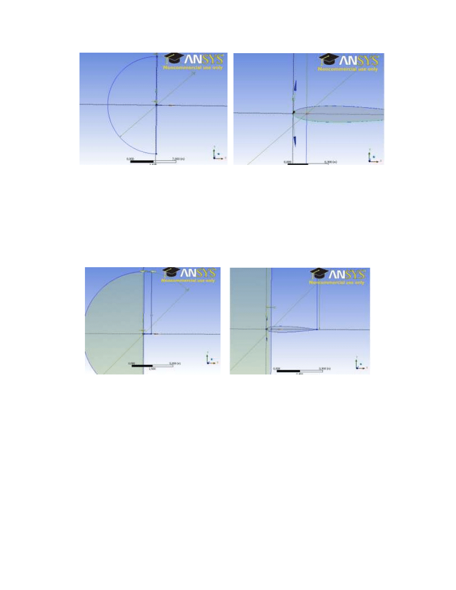
2
Fig. 1. Half of the cylinder (Sketching mode).
5. Make a surface using the prepared sketch. Go to Modeling mode, select
Concept/Surfaces from sketches. Change Add Material to Add frozen under
Operation (new fluid element will be made).
6. Add new Sketch in the XY-Plane. Go to the Sketching mode. Make a rectangular 0,9 x
7,5m. The end points of the bottom side of rectangular are : (0,1 0), (1 0). Use
Coincident in order to attach some lines with the other. Fig. 2 shows the rectangular in
the sketching mode.
Fig. 2. Rectangular placed next to half of the cylinder.
7. Add new Sketch in the XY-Plane. Make a rectangular 6 x 7,5m. The end points of the
bottom side of rectangular are : (1 0), (6 0). Use Coincident option to connect some lines
together.
8. Make the two surfaces. Switch to Modeling mode (Concept/Surfaces from sketches),
select both rectangles, Change Add Material to Add frozen under Operation.
9. Subtract the airfoil surface from fluid areas surrounding the body (half of circle and
rectangle). Create/Boolean/Subtract. Preserve Tool Bodies set to No. See fig. 3
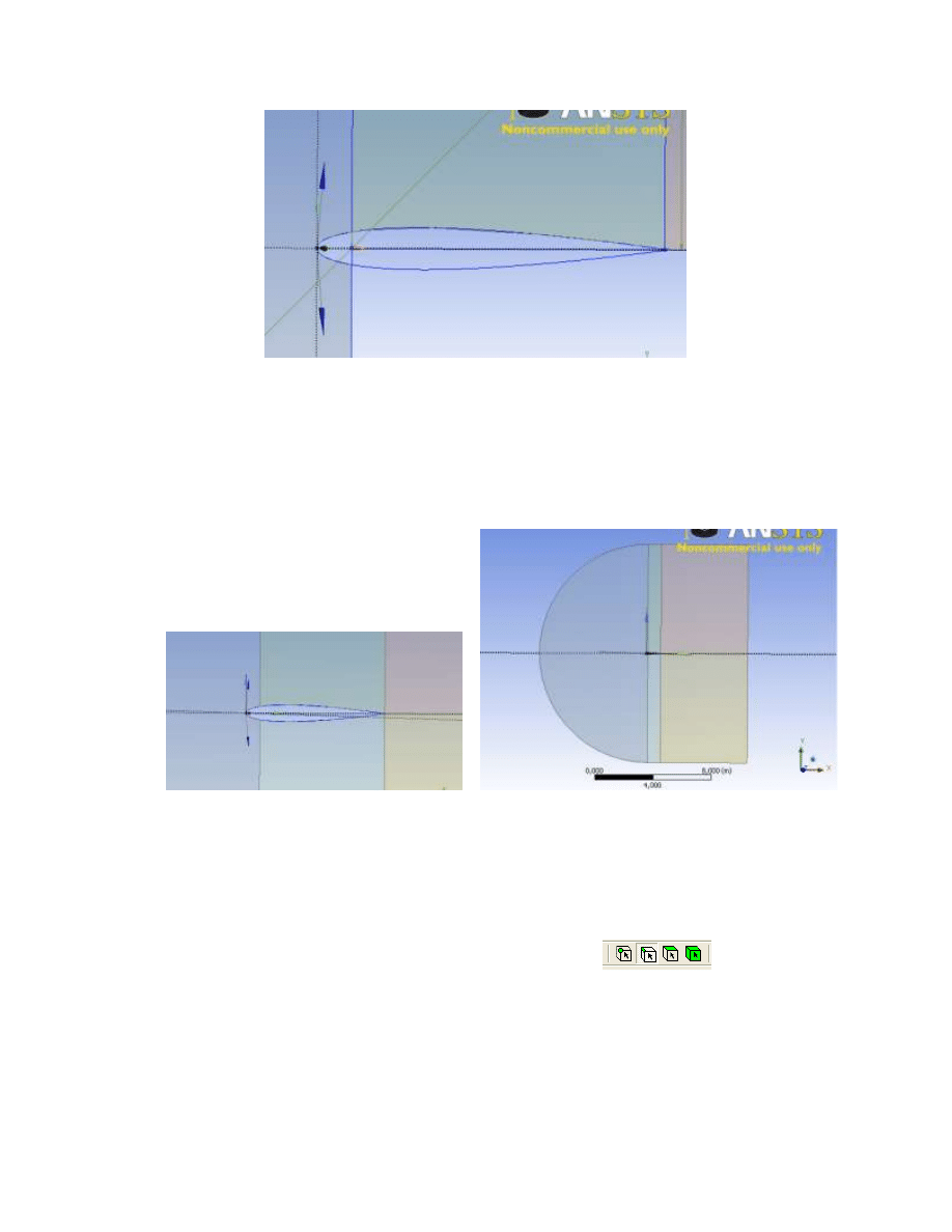
3
Fig. 3. Airfoil body subtracted from half of cylinder and rectangular.
10. Mirror the two rectangles (one with subtracted airfoil) in the zx-plane. (Create/Body
Operation/Mirror, select zx-plane)
11. Connect the five faces together to ensure that there are linked together (Tools/Joint). See
fig. 5
Fig. 4. The five faces surrounding the airfoil.
12. Make the fluid volume (surface). This will be done by making a one part from 5 surfaces
listed under Parts. First, deactivate the Line Body, right click and select Suppress (This
body will not be used for meshing). Select the remaining five bodies (use Ctrl or Shift
buttons to select multiple bodies), right click and select Form New Part.
13. Provide the names indicating the airfoil surface (wall) and boundary in the freestreem
(pressure far field). Select the line option in the top menu
, select the
curves corresponding to the airfoil, right click, select Named Selection and put the curves
under Geometry. Specify the name ‘wall_airfoil’ under Named Selection. In a similar
way select the curves at the boundaries of the computational domain, provide the name
‘pressure_far_field’. Save the project (Drive D, folder Student, make your own folder
there, if needed). Close Design Modeler (green project part).
4
Meshing
1. Add the Mesh button (drag and drop) in the Project Schematic (Workbench) and link it
to the present Geometry.
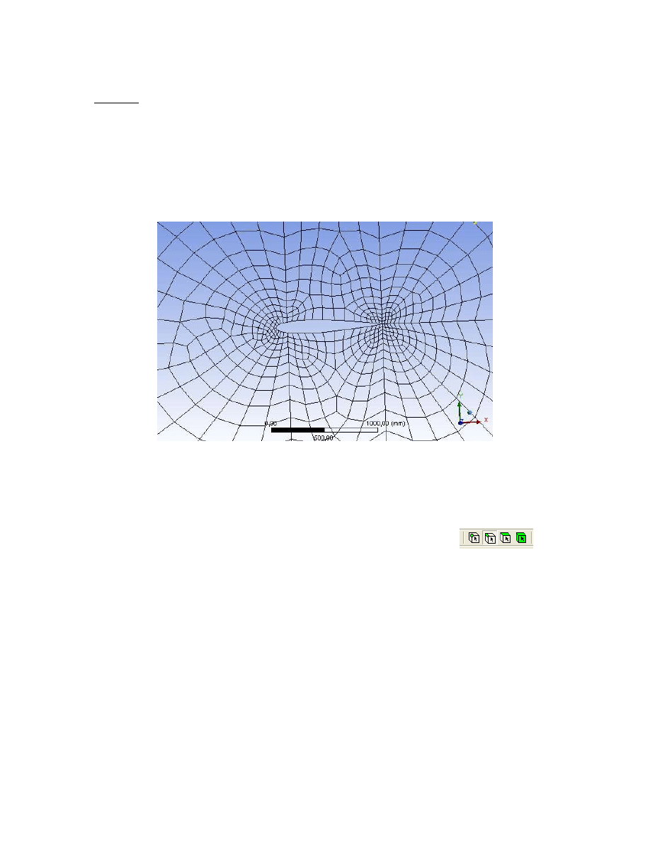
2. Click on the Mesh button. Change the settings under the Physics reference from
Mechanical to CFD, use Fluent as Solver Preference. Generate a preliminary
(unstructured) mesh (see fig. 5). The mesh is very coarse near to the surface and it cannot
be used for viscous flow simulations.
Fig. 5. Preliminary mesh generated over airfoil using the global mesh settings.
3. The block-structured grid can be generated. Note that each surface has to be mapped virtually
onto the rectangular. In order to do this one has to specify a proper number of elements on
selected edges.
- Specify about ~100 of nodes on edges perpendicular to surface, with bias factor ~4000.
The mesh has to be refined near to the wall. First, select line option
in the
top menu, next select the edge(s) from the screen, click on Mesh, right click, select
Sizing. Specify the element size under Type/Element Size or change to Number of
Divisions under Type and specify the number of elements.
- keep the same number of elements on edges corresponding to opposite sides of virtual
rectangular. Otherwise, the mapped scheme cannot be applied for making the bloc-
structured mesh.
- the boundary layer mesh (inflation) cannot be used now.
4. Right click on the Mesh, select Mapped Mesh Meshing. Add all faces under Geometry.
Select Quadrilaterals under Method. Click on Generate button. Fig. 6 shows the view of the
computational mesh.
5. Save the meshing project. Export the mesh to *.msh Fluent file. File\Export.
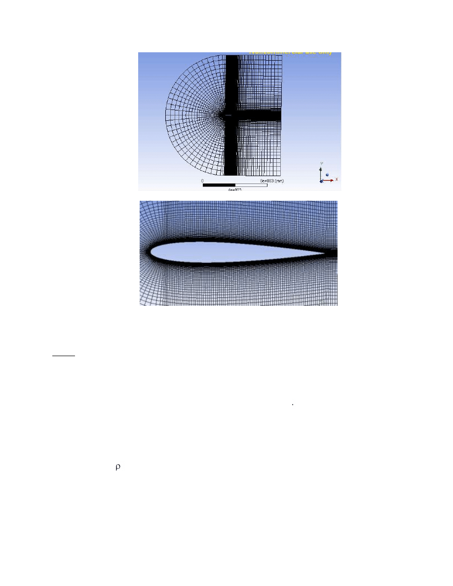
5
Fig. 6 Final block-structured mesh
Fluent
1. Read the mesh file. Check the scale. Keep the length in m. Rotate the mesh by 1.25 deg.
Mesh/Rotate/ set -1.25 deg.
2. Set-up the computations in Fluent. The inlet Mach number is 0.8, the Reynolds number
based on chord length of the airfoil and inlet velocity is 1.5 10
6
.
3. Select appropriate turbulence model and specify the boundary conditions on pressure far
field boundary.
4. Run the computations. The residuals should fall down below 10
-5
. The numerical scheme
should be set to second order upwind.
5. Verify the pressure, temperature and velocity fields. Verify the lift and drag coefficients
c
d
=F
d
/(0.5 u
2
A), (A is equal to 1) and compare them with literature data (activate the
freestrem conditions in Report/Reference values). Note that the forces have to be
computed with respect to direction of the incoming flow. This is why the mesh has been
rotated in the beginning by 1.25 deg. It means that the lift and drag coefficients can now
easily be obtained in Report/Forces/Direction vector by setting 1 and 0 factors under
Direction vector. x=1 y=0 for drag, x=0, y=1 for lift.
Wyszukiwarka
Podobne podstrony:
GPC SE~1 id 193962 Nieznany
Abolicja podatkowa id 50334 Nieznany (2)
4 LIDER MENEDZER id 37733 Nieznany (2)
katechezy MB id 233498 Nieznany
metro sciaga id 296943 Nieznany
perf id 354744 Nieznany
interbase id 92028 Nieznany
Mbaku id 289860 Nieznany
Probiotyki antybiotyki id 66316 Nieznany
miedziowanie cz 2 id 113259 Nieznany
LTC1729 id 273494 Nieznany
D11B7AOver0400 id 130434 Nieznany
analiza ryzyka bio id 61320 Nieznany
pedagogika ogolna id 353595 Nieznany
Misc3 id 302777 Nieznany
cw med 5 id 122239 Nieznany
więcej podobnych podstron