
Winkler, Arduino workshop, sensors, p.1
Envision Art 01: the responsive screen
Prof. Fabian Winkler
Spring 2007
Arduino Workshop
Arduino
see: http://www.arduino.cc
Arduino is an open-source physical computing platform based on a simple i/o board,
and a development environment for writing Arduino software. Arduino can be used to
develop interactive objects, taking inputs from a variety of switches or sensors, and
controlling a variety of lights, motors, and other outputs. Arduino projects can be
stand-alone, or they can communicate with software running on your computer (e.g.
Flash, Processing, MaxMSP). The open-source IDE can be downloaded for free.
•
Arduino is an open source project, owned by nobody and supported by many.
•
The Team is composed of Massimo Banzi, David Cuartielles, Tom Igoe, Gianluca
Martino, David Mellis and Nicholas Zambetti
•
Yaniv Steiner and Giorgio Olivero have been supporting the project and are
working at using it with the Instant Soup platform.
•
The Arduino platform includes the avr-gcc tool chain, uisp, and the Procyon
AVR-LIB by Pascal Stang.
•
The Arduino language syntax is based on Wiring by Hernando Barragan
Why using Arduino?
•
It is flexible, offers a variety of digital and analog inputs, SPI and serial interface
and digital and PWM outputs
•
It is easy to use, connects to computer via USB and communicates using standard
serial protocol, runs in standalone mode and as interface connected to
PC/Macintosh computers
•
It is inexpensive, around $30 per board and comes with free authoring software
•
It is an open-source project, software/hardware is extremely accessible and very
flexible to be customized and extended
•
Arduino is backed up by a growing online community, lots of source code is
already available and we can share and post our examples for others to use, too!
Winkler, Arduino workshop, sensors, p.2
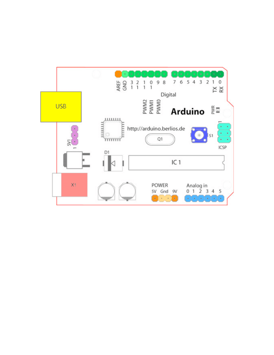
Introduction to the Arduino Board
(see: http://www.arduino.cc/en/Guide/Board)
Looking at the board from the top down, this is an outline of what you will see (parts of
the board you might interact with in the course of normal use are highlighted):
Starting clockwise from the top center:
•
Analog Reference pin (orange)
•
Digital Ground (light green)
•
Digital Pins 2-13 (green)
•
Digital Pins 0-1/Serial In/Out - TX/RX (dark green) - These pins cannot be used
for digital i/o (digitalRead and digitalWrite) if you are also using serial
communication (e.g. Serial.begin).
•
Reset Button - S1 (dark blue)
•
In-circuit Serial Programmer (blue-green)
•
Analog In Pins 0-5 (light blue)
•
Power and Ground Pins (power: orange, grounds: light orange)
•
External Power Supply In (9-12VDC) - X1 (pink)
•
Toggles External Power and USB Power (place jumper on two pins closest to
desired supply) - SV1 (purple)
•
USB (used for uploading sketches to the board and for serial communication
between the board and the computer; can be used to power the board) (yellow)
Winkler, Arduino workshop, sensors, p.3
Sensors
Sensors are electronic devices that measure a physical quality such as light or
temperature and convert it to a voltage. This process of changing one form of energy
into another is called transduction. Often, sensors are also referred to as transducers.
Sensors can be broadly classified in two categories: digital sensors and analog sensors.
A digital sensor's output can only be in one of two possible states. It is either ON (1)
often +5V, or OFF (0), 0V. Most digital sensors work with a threshold. Is the incoming
measurement below the threshold, the sensor will output one state, is it above the
threshold, the sensor will output the other state.
In contrast to a digital sensor, an analog sensor's output can assume any possible value
in a given range. Very often the output of an analog sensor is a variable resistance that
can be used to control a voltage. Rather than only being able to toggle between two
states ( cf. a digital sensor) the analog sensor can output an almost infinite range of
values.
In the following examples we will take a look at a couple of digital and analog sensors.
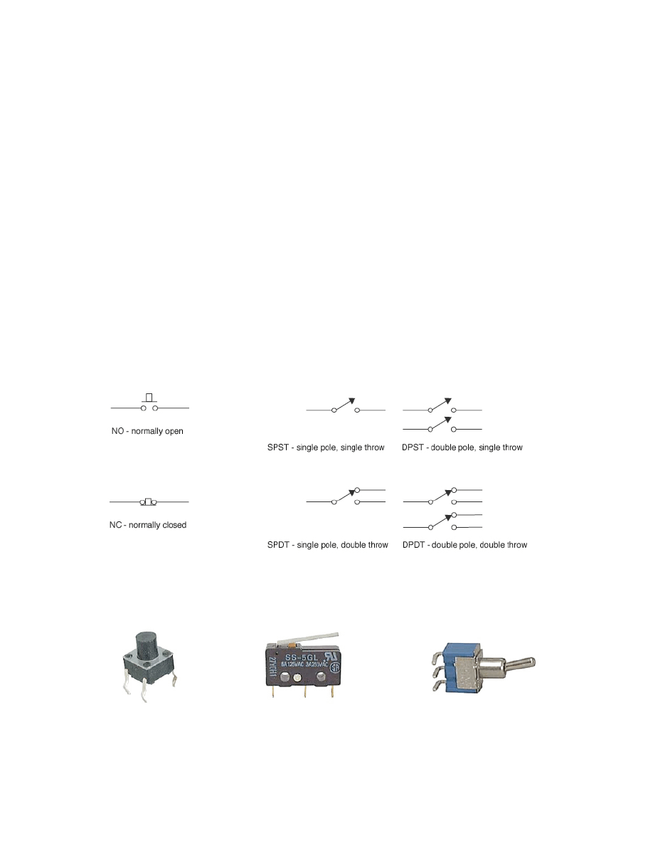
We will begin with the simplest digital sensor, the switch. When a switch is open, no
current flows. In contrast, when a switch is closed, current flows (i.e. closed = ON). A
switch that stays in the position it was put is called a latching switch. Switches can be
spring loaded (e.g. microswitches/snap action switches), in this case they are called
momentary. A simple switch can be Normally Open (NO) or Normally Closed (NC).
tactile switch/
subminiature switch/
miniature toggle switch
pushbutton switch
snap action switch
NO NC C
Winkler, Arduino workshop, sensors, p.4
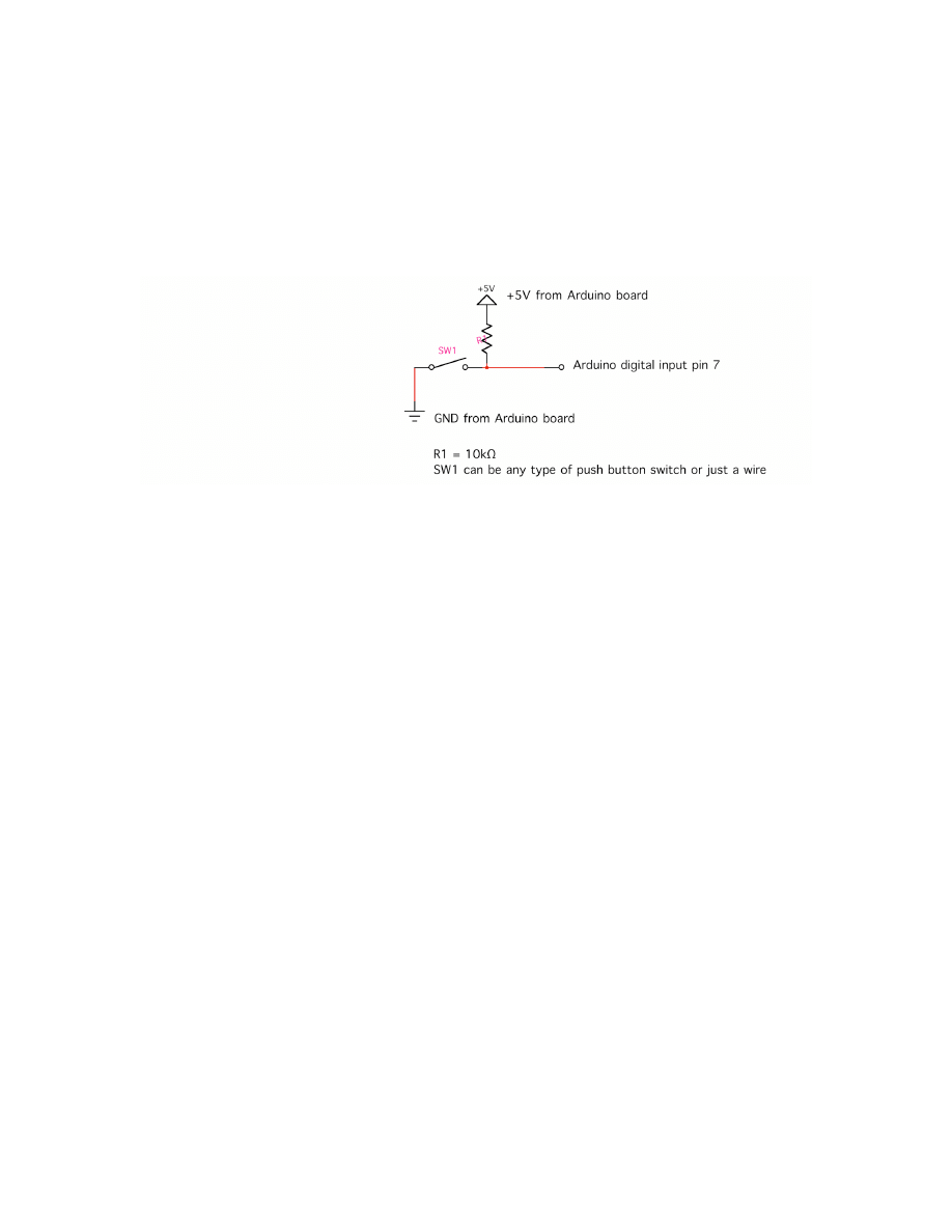
Connecting a Switch to the Arduino Board
This is probably the simplest possible example to get started with Arduino. It uses an
external switch and the Arduino board to turn ON or OFF the on-board LED (see:
http://www.arduino.cc/en/Tutorial/Pushbutton):
1. Connect a switch (you can replace the switch with a plain jumper wire) to the Arduino
board in the following way:
Why do we need the resistor R1? R1 guarantees that the Arduino’s digital input pin 7 is
connected to a constant voltage of +5V whenever the push button is not pressed. If the
push button is pressed, the signal on pin 7 drops to ground (GND), at the same time the
Arduino’s +5V power is connected to GND, we avoid a shorted circuit by limiting the
current that can flow from +5V to GND with a resistor (1 - 10 KΩ). Also, if there was no
connection from pin 7 to +5V at all, the input pin would be “floating” whenever the
pushbutton is not pressed. This means that it is connected neither to GND nor to +5V,
picking up electrostatic noise leading to a false triggering of the input.
2. Open the Arduino software and write the following code:
/* Basic Digital Read
* ------------------
*
* turns on and off a light emitting diode(LED) connected to digital
* pin 13 (onboard LED, when pressing a pushbutton attached to pin 7.
* It illustrates the concept of Active-Low, which consists in
* connecting buttons using a 1K to 10K pull-up resistor.
*
* Created 1 December 2005
* copyleft 2005 DojoDave <http://www.0j0.org>
* http://arduino.berlios.de
*
*/
int ledPin = 13; // choose the pin for the LED
int inPin = 7; // choose the input pin (for a pushbutton)

Winkler, Arduino workshop, sensors, p.5
int val = 0; // variable for reading the pin status
void setup() {
pinMode(ledPin, OUTPUT); // declare LED as output
pinMode(inPin, INPUT); // declare pushbutton as input
}
void loop(){
val = digitalRead(inPin); // read input value
if (val == HIGH) { // check if the input is HIGH
// i.e. button released
digitalWrite(ledPin, LOW); // turn LED OFF
} else {
digitalWrite(ledPin, HIGH); // turn LED ON
}
}
3. Download the code into the Arduino board:
a. Select the serial device of the Arduino board from the Tools | Serial Port menu.
On the Mac, this should be something with /dev/tty.usbserial in it.
b. Compile your code using the “Verify” button in the top left corner of the software
window.
c. Push the reset button on the board then immediately click the
Upload
button in
the environment (don't wait for the board to "come back to life" before pressing
the upload button). Wait a few seconds. If successful, the message "Done
uploading." will appear in the status bar.
d. You are ready to test your first Arduino sensor application.
(For more information on setting up the Arduino see:
http://www.arduino.cc/en/Guide/MacOSX, http://www.arduino.cc/en/Guide/Windows).
Serial Output
Eventually we would like the Arduino board to send sensor readings to a graphics
application on the PC. This can be accomplished by using a communication strategy
called “serial communication” to exchange the necessary data. In serial communication,
data is transmitted one bit at a time over a single path. In order for the Arduino board
and the host computer to understand each other, we need to work with a specific serial
data protocol that defines e.g. communication speed (baud rate) and how to begin/end
reading data. See chapter 7: “Communicating between Computers” in Dan O’Sullivan
Tom Igoe’s book “Physical Computing” for more information on serial communication.

Winkler, Arduino workshop, sensors, p.6
Let’s change the above program, so that it also sends a message to the host computer
via serial communication in addition to turning the LED on and off:
/* Serial Write Basic
* ------------------
*
* turns on and off a light emitting diode(LED) connected to digital
* pin 13. The LED will light up when pressing a button. At the same
* time, Arduino will send two different strings over the serial
* port depending if the button is pressed or released.
*
* Created 1 December 2005
* copyleft 2005 DojoDave <http://www.0j0.org>
* http://arduino.berlios.de
*
*/
int ledPin = 13; // select the pin for the LED
int buttonPin = 7; // select the pin for the button
int val = 0; // variable to store the data from the serial port
void setup() {
pinMode(ledPin,OUTPUT); // declare the LED's pin as output
pinMode(buttonPin, INPUT); // declare the button pin as input
Serial.begin(9600); // connect to the serial port
}
void loop () {
// read the button and store the value
val = digitalRead(buttonPin);
// if the button is at HIGH, turn the LED on, off otherwise
if (val == HIGH) {
Serial.print("HIGH");
digitalWrite(ledPin, HIGH);
} else {
Serial.print("LOW");
digitalWrite(ledPin, LOW);
}
}
Winkler, Arduino workshop, sensors, p.7
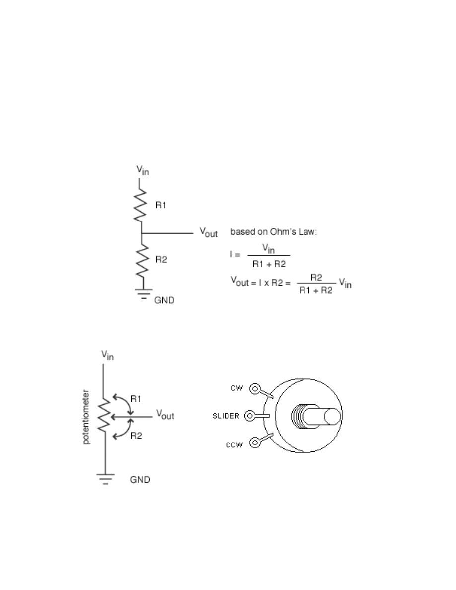
Analog Sensors
Analog sensors, such as a photocell often work like a variable resistor the resistance of
which is directly influenced by the condition it measures (in the case of the photocell it
is the amount of light). Often a voltage divider circuit is used to turn the sensor’s
changing resistance into a proportional change of voltage that can be understood better
by ICs/microcontrollers (such as the Arduino) that you connect the sensor to.
In the following circuit diagram, a potentiometer is used as a voltage divider, with its
slider dividing the overall voltage into two parts R1 and R2. We see that a voltage divider
produces a predictable fraction of the input voltage as the output voltage.
This general description of a voltage divider is related to the potentiometer as follows:
Winkler, Arduino workshop, sensors, p.8
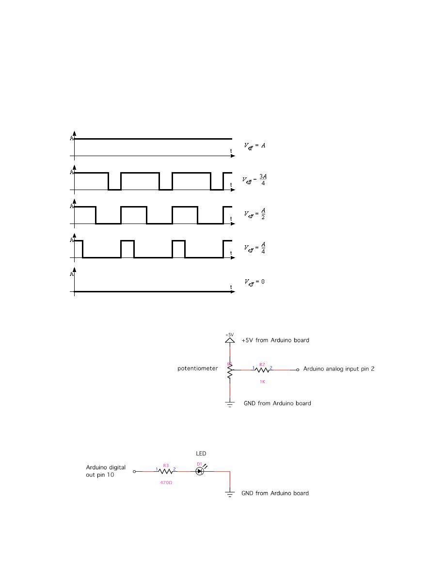
Connecting a Potentiometer to the Arduino Board
In this example we would like to connect a potentiometer to the Arduino and control the
brightness of an external LED by turning the potentiometer’s knob. The Arduino board
uses pulse width modulation (PWM) to dim the LED. In effect, the digital output is pulsed
rapidly (turning the LED ON and OFF many times per second) to create the impression of
the LED being evenly dimmed.
duty cycle 100%
duty cycle 75%
duty cycle 50%
duty cycle 25%
duty cycle 0%
1. Build the following two simple circuits and connect them to the Arduino board:

Winkler, Arduino workshop, sensors, p.9
2. Write the following code and upload it onto the board:
/* Analog Read Send
* ----------------
*
* turns on and off a light emitting diode(LED) connected to digital
* pin 13. The amount of time the LED will be on and off depends on
* the value obtained by analogRead(). In the easiest case we connect
* a potentiometer to analog pin 2. Sends the data back to a computer
* over the serial port.
*
* Created 24 January 2007
* copyleft 2007 Fabian Winkler
*
*/
int potPin = 2; // select the input pin for the potentiometer
int ledPin = 10; // select the pin for the LED
int val = 0; // variable to store the value coming
//from the sensor
int pwmVal = 0; // variable for PWM output
void setup() {
pinMode(ledPin, OUTPUT); // declare the ledPin as an OUTPUT
Serial.begin(9600); // use the serial port to send the
// values back to the computer
}
void loop() {
val = analogRead(potPin); // read the value from the sensor
Serial.println(val); // print the value to the serial port
pwmVal = val/4;
// PWM is 8bit (0-255), analog in is 10bit
// (0-1023), so we need to convert
analogWrite(ledPin, pwmVal);
}
Winkler, Arduino workshop, sensors, p.10
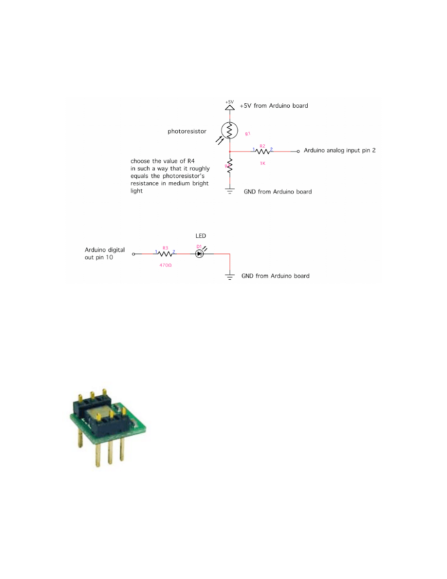
Connecting a Photocell to the Arduino Board
This example shows you how to read a photocell (photoresistor) with the Arduino. The
code is analog to the example above.
Sensors with PWM output
Some more advanced sensors, such as the MEMSIC2125 dual axis accelerometer sensor
use a different way to output sensor values, which is neither a straight ON or OFF signal,
nor is it a variable voltage range. The output of these sensors is pulse width modulated
(see page 8 above). The width (i.e. timing) of the pulses that the sensor sends out can
be easily measured with the Arduino board’s pulseIn function (see:
http://www.arduino.cc/en/Reference/PulseIn).
MEMSIC2125 dual axis accelerometer
Winkler, Arduino workshop, sensors, p.11
Appendix
Signal conditioning
What to do when the voltage range that a sensor provides and the range of an Arduino’s
input pin don’t match up? The following is a tutorial from Acroname Robotics and can
be found online at:
http://www.acroname.com/robotics/info/articles/interface/interface.html
Contents
•
Introduction
•
Dividing Voltages
•
Amplifying Voltages
•
Shifting Voltages
•
Combining Conversions
•
Conversion Impurities
•
Power Supply Ideas
•
Further Reading
Introduction
The interface of various sensors to a controller like the Arduino typically involves either
conditioning or converting voltage levels into the range the controller requires. Many
systems use A/D converters to make the sensor value relevant in a program or data
logging configuration. These converters have a fixed range of voltages they can convert
from with 0-5V being by far the most common.
Sensors often create voltages in different ranges than those required by the controllers
they are being interfaced to which requires the conversion of one voltage to another.
This conversion often breaks down into a combination one or more of three types,
amplification, dividing, and shifting.
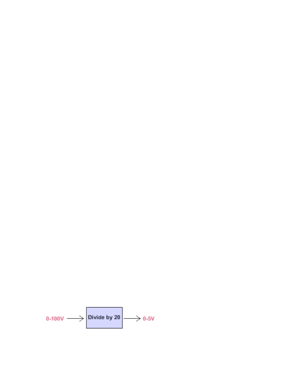
Dividing Voltages
Voltage dividing is probably the easiest transformation you can perform on sensor
outputs to alter the value being connected to a microcontroller or other circuit.
The mathematical equivalent of what you are trying to achieve when dividing voltages is
a simple division. For instance, say you have a sensor that outputs 0-100V and you
want to convert this to 0-5V for interface to the A/D input on your Arduino. The goal
would be to create a 20:1 ratio of voltage which means dividing the original sensor
output voltage by a factor of 20. So we need a small circuit that will accomplish the
following graphically:
Winkler, Arduino workshop, sensors, p.12
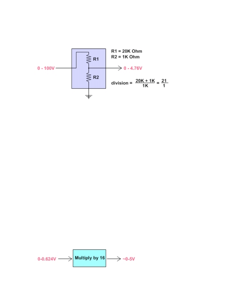
The easiest way to accomplish this division is using a few resistors to form a voltage
divider. The resistors are wired up in series to create intermediate voltages based with
the desired division. The above example could be accomplished as follows:
This voltage divider uses the input as the top of the resistor ladder and ground as the
bottom. The actual division is defined by the proportion of resistance between the two
resistors.
Notice the above circuit does not work out to an exact division by 20. This is because
the resistors used are commonly found resistor values. Precision resistors with exact
tolerances can be used but are often not needed since the original output of sensors
typically varies. Here the resulting output voltage is slightly below the maximum of 5V
but with a reasonable A/D converter like the 10-bit converters used in the Arduino
board would still offer plenty of dynamic range in the sensor readings.
Amplifying Voltages
Voltage amplification is required for a class of sensors that create small voltages. Often
sensors of this type are converting some sort of physical energy such as acceleration,
temperature, or other minimal physical force into a voltage. This conversion is often an
inefficient conversion and the measured energy is minimal which results in very small
voltages generated by the sensor. To make these small voltages meaningful, they must
be amplified to a usable level.
The equation for amplification is the exact opposite of dividing. You want to multiply
the output voltage from a sensor to gain the full range of your A/D input or other
interfaced circuit. Lets say you have an accelerometer which measures accelerations in
g (gravity) units. A sensor like this may have a response of 312mV/g which means the
sensor will generate 0.312V for each gravity unit of force it encounters. Now, say you
would like to measure up to 2 gravity units (2g) with your detector with the full range of
your 0-5V A/D converter. This means you need to multiply the output voltage of your
accelerometer by a factor of about 16 to get the desired range and sensitivity in your
measurements. So we want to accomplish the following graphically:
Winkler, Arduino workshop, sensors, p.13
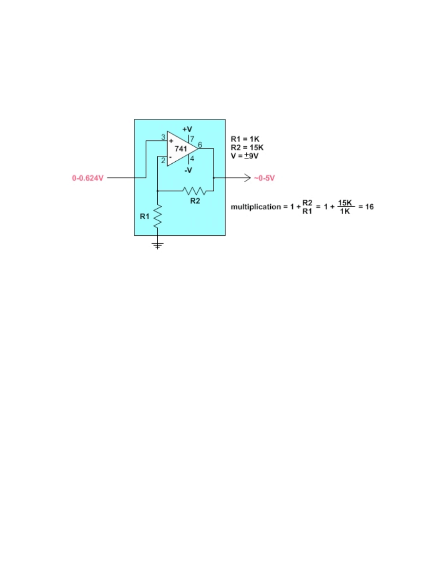
Probably the most common way to multiply a voltage is using an amplifier. Here, we will
use a common Operational Amplifier (Op Amp) to multiply the voltage. These Op Amp
circuits are extremely common in electronics and there are volumes devoted specifically
to the various characteristics and performance of each. We use one of the original
versions which is widely available and easy to interface called the 741. Here is one
circuit that will amplify the voltage by a factor of about 16:
There are some things to note about this circuit. Again, changing resistance values
gives a different voltage amplification (multiplication). The small numbers indicate the
pins of the 741 package that you would connect to for this circuit (it is an 8 pin chip).
Also, notice the additional power supply which is both positive and negative. This is
very common for Op Amp circuits. Since the Op Amp is powered by a plus/minus
voltage of 9V, the absolute output can at best be 9V. In practice, the output voltage will
probably be slightly less.
The gain for this amplifier may not be exactly linear, depending on the input and output
voltages. This can often be hidden in the noise of the sensor and accuracy of the A/D
conversion on the other end but it should be considered. The higher the gain of an
amplifier, the larger the margin of error and noise.
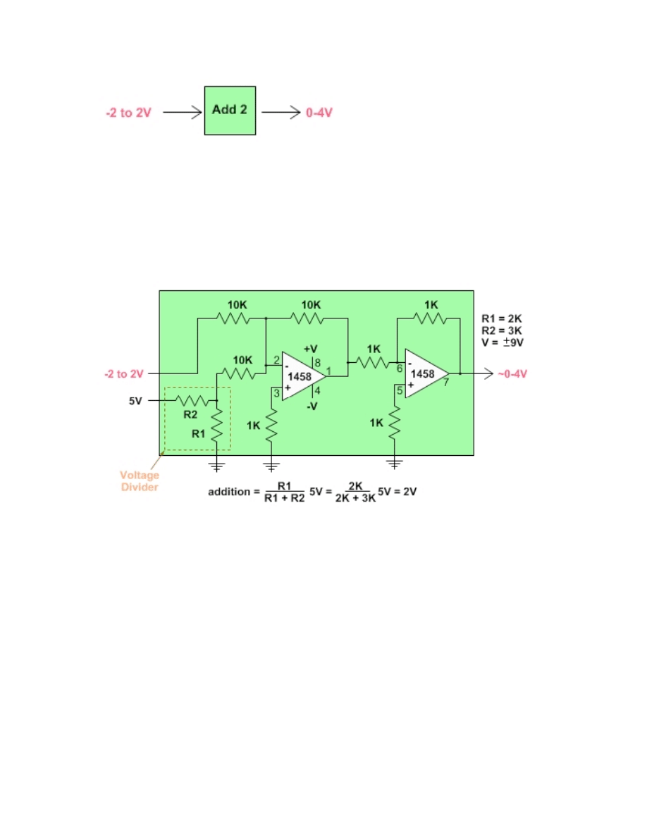
Shifting Voltages
Shifting voltages can be a requirement for sensor data that are generated symmetrically
about a common (often ground) voltage. A simple example of this would be a motor
acting as a generator where spinning in one direction creates a positive voltage and
spinning in the other direction creates a negative voltage. Since most common A/D
converters in microcontrollers deal with a 0-Vcc range for conversions, sensors that are
symmetric about the ground voltage reference need to be shifted into the 0-Vcc range.
The equation for shifting is then the addition or subtraction of an offset from the
original sensor's voltage. For example, if your sensor produces -2 to 2V, you would
want to add 2V to the output for reading with a common 0-5V A/D converter. This
addition would result in a final output of 0-4V which the A/D converter could then use.
This conversion looks like this graphically:
Winkler, Arduino workshop, sensors, p.14
This circuit is a two-stage summing amplifier using an Op-Amp chip (the 1458) that
houses two op-amps on a single chip. Notice there are some fixed values of resistors
that essentially create a voltage summing circuit. The input on one side is a resistor
network that creates a fixed voltage to sum with the input voltage. The variable resistor
values change this resistor network's set voltage. You could substitute a potentiometer
for R1 and R2 to make the addition variable, by twisting the potentiometer.
The addition circuit also requires a plus/minus 9V power supply for the op-amps. In
addition, a tap from the 5V supply used for the logic is used although this could be
done with the positive 9V side as well, provided the voltages are computed correctly.
Combining Conversions
So the above conversions define addition, subtraction, multiplication, and division of a
voltage. Each of these conversions can be thought of in isolation as shown above or
they can be combined to create composite conversions. We essentially have an algebra
of blocks we can use to achieve a wide variety of overall conversions.
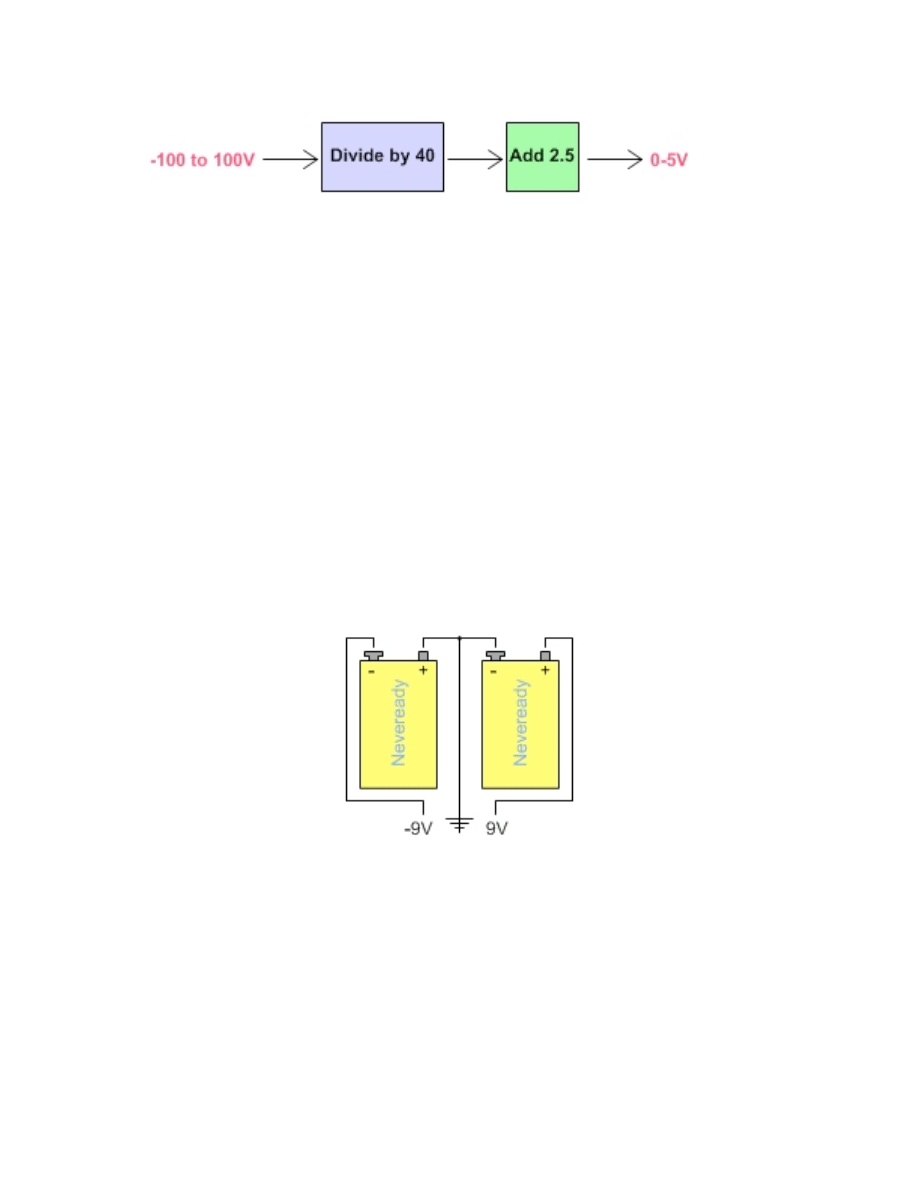
Say you have a sensor that creates -100 to 100V and you want to read the value with a
0-5V A/D converter. You would need to scale down the original voltage to -2.5 to 2.5V
first and then offset the result by adding 2.5V to get the result into the desired range of
0-5V for your A/D converter. You can chain together the conversions for such an effect
which would look like this graphically:
Winkler, Arduino workshop, sensors, p.15
Conversion Impurities
The above conversions all introduce impurities in the resulting signal in the form of
noise, non-linearity, and other corruptions of the original input voltage. Care must be
taken to minimize the number of stages and also to order them for reduced error.
Testing and careful thought can typically reduce these impurities to a minimum but they
cannot be disregarded.
There is a general rule of thumb with regard to these introduced impurities. The more
you are changing the original voltage, the more impurities you will introduce. For
instance, an amplification of 100x would be generally noisier than one of 2x.
Power Supply Ideas
Several of these circuits require a plus/minus 9V supply for the Op Amps. This can
readily be accomplished using two standard 9V batteries. More sophisticated options
include standard power supplies, charge pumps and inverters and several other options.
The 9V battery is cheap, simple and it works well. Op Amp circuits tend to be pretty
efficient so the batteries should last quite some time.
Circuit Diagram of +-9V Battery Supply
Further Reading
The subject of sensor interfaces is vast. This article attempts to give some basics that
are easy, practical, and quick to implement. Here are two great references to consider:
* The Art of Electronics, by Horowitz and Hill
* Op Amp IC Circuits, by Forrest M. Mims III
Wyszukiwarka
Podobne podstrony:
integracja sensoryczna5 id 2181 Nieznany
APS NCBIR (sensory) id 67332 Nieznany
4 Sensoryka id 37966 Nieznany
Ogrod sensoryczny id 333966 Nieznany
integracja sensoryczna5 id 2181 Nieznany
arduino mini user guide id 6826 Nieznany (2)
Arduino Lab 1 id 68202 Nieznany
f4 sensor properties rev1 id 16 Nieznany
arduino talk id 68271 Nieznany
Abolicja podatkowa id 50334 Nieznany (2)
4 LIDER MENEDZER id 37733 Nieznany (2)
katechezy MB id 233498 Nieznany
metro sciaga id 296943 Nieznany
perf id 354744 Nieznany
interbase id 92028 Nieznany
Mbaku id 289860 Nieznany
Probiotyki antybiotyki id 66316 Nieznany
miedziowanie cz 2 id 113259 Nieznany
więcej podobnych podstron