
DRAFT FOR DEVELOPMENT
DD ENV
1992-1-2:1996
Eurocode 2: Design of
concrete structures —
Part 1.2 General rules —
Structural fire design —
(together with United Kingdom
National Application Document)
ICS 91.040; 91.080.40
Licensed copy:Heriot Watt University, 20/04/2004, Uncontrolled Copy, © BSI

DD ENV 1992-1-2:1996
This Draft for Development,
having been prepared under
the direction of the Sector
Board for Building and Civil
Engineering, was published
under the authority of the
Standards Board and comes
into effect on
15 July 1996
© BSI 03-2000
The following BSI references
relate to the work on this Draft
for Development:
Committee reference B/525/2
ISBN 0 580 25809 2
Committees responsible for this
Draft for Development
The preparation of this Draft for Development was entrusted by Technical
Committee B/525, Building and civil engineering structures, to
Subcommittee B/525/2, Structural use of concrete, upon which the following
bodies were represented:
Association of Consulting Engineers
British Cement Association
British Precast Concrete Federation Ltd.
Department of the Environment (Property and Buildings Directorate)
Department of Transport (Highways Agency)
Federation of Civil Engineering Contractors
Institution of Civil Engineers
Institution of Structural Engineers
Steel Reinforcement Commission
Amendments issued since publication
Amd. No.
Date
Comments
Licensed copy:Heriot Watt University, 20/04/2004, Uncontrolled Copy, © BSI

DD ENV 1992-1-2:1996
© BSI 03-2000
i
Contents
Page
Committees responsible
Inside front cover
National foreword
ii
Foreword
2
Text of National Application Document
v
Text of ENV 1992-1-2
7
Licensed copy:Heriot Watt University, 20/04/2004, Uncontrolled Copy, © BSI

DD ENV 1992-1-2:1996
ii
© BSI 03-2000
National foreword
This Draft for Development was prepared by Subcommittee B/525/2 and is the
English language version of ENV 1992-1-2:1995 Eurocode 2: Design of concrete
structures — Part 1.2: General rules — Structural fire design,
as published by the
European Committee for Standardization (CEN). This Draft for Development
also includes the United Kingdom (UK) National Application Document (NAD)
to be used with the ENV in the design of buildings to be constructed in the UK.
ENV 1992-1-2 results from a programme of work sponsored by the European
commission to make available a common set of rules for the structural and
geotechnical design of building and civil engineering works.
This publication should not be regarded as a British Standard.
An ENV is made available for provisional application, but does not have the
status of a European Standard. The aim is to use the experience gained to modify
the ENV so that it can be adopted as a European Standard. The publication of this
ENV and its National Application Document should be considered to supersede
any reference to a British Standard in previous DD ENV Eurocodes concerning
the subject covered by these documents.
The values for certain parameters in the ENV Eurocodes may be set by individual
CEN Members so as to meet the requirements of national regulations. These
parameters are designated by|_|in the ENV.
During the ENV period of validity, reference should be made to the supporting
documents listed in the National Application Document (NAD).
The purpose of the NAD is to provide essential information, particularly in
relation to safety, to enable the ENV to be used for buildings constructed in the
UK and the NAD takes precedence over corresponding provisions in the ENV.
The Building Regulations 1991, Approved Document A 1992, draws attention to
the potential use of ENV Eurocodes as an alternative approach to Building
Regulation compliance. ENV 1992-1-2 is considered to offer such an alternative
approach, when used in conjunction with its NAD.
Users of this document are invited to comment on its technical content, ease of
use and any ambiguities or anomalies. These comments will be taken into account
when preparing the UK national response to CEN on the question of whether the
ENV can be converted to an EN.
Comments should be sent in writing to the Secretary of Subcommittee B/525/2,
BSI, 389 Chiswick High Road, London W4 4AL, quoting the document reference,
the relevant clause and, where possible, a proposed revision, by 31 October 1996.
Summary of pages
This document comprises a front cover, an inside front cover, pages i to x,
the ENV title page, pages 2 to 63 and a back cover.
This standard has been updated (see copyright date) and may have had
amendments incorporated. This will be indicated in the amendment table on the
inside front cover.
Licensed copy:Heriot Watt University, 20/04/2004, Uncontrolled Copy, © BSI

DD ENV 1992-1-2:1996
© BSI 03-2000
iii
National Application
Document
for use in the UK with
ENV 1992-1-2:1995
Licensed copy:Heriot Watt University, 20/04/2004, Uncontrolled Copy, © BSI

DD ENV 1992-1-2:1996
iv
© BSI 03-2000
Contents of
National Application Document
Page
Introduction
v
1
Scope
v
2
Partial factors, combination factors and other values
v
3
Tabulated data
v
4
Reference standards
x
5
Additional recommendations
x
Table 1 — Values to be used in referenced clauses instead of boxed values
v
Table N4.1 — Minimum dimensions and axis distances for reinforced
concrete columns; rectangular and circular section
v
Table N4.2 — Minimum wall thickness of non load-bearing
walls (partitions)
vi
Table N4.3 — Minimum dimensions and axis distances for
load-bearing reinforced concrete walls
vi
Table N4.4 — Minimum dimensions and axis distances for
reinforced and prestressed concrete tensile members
vi
Table N4.5 — Minimum dimensions and axis distances for simply
supported beams made with reinforced and prestressed concrete
vii
Table N4.6 — Minimum dimensions and axis distances for
continuous beams made with reinforced and prestressed concrete
vii
Table N4.7 — Reinforced and prestressed concrete continuous I
beams: increased beam width and web thickness for conditions
according to Table N4.6
viii
Table N4.8 — Minimum dimensions and axis distances for reinforced
and prestressed concrete simply supported one-way and two-way slabs
viii
Table N4.9 — Minimum dimensions and axis distances for reinforced
and prestressed concrete flat slabs
viii
Table N4.10 — Minimum dimensions and axis distance for two-way
spanning, simply supported ribbed slabs in reinforced or
prestressed concrete
ix
Table N4.11 — Minimum dimensions and axis distances for
two-way spanning ribbed slabs in reinforced or prestressed concrete
with at least one restrained edge
ix
Table 2 — Reference in EC2-1.2 to other codes and standards
x
Licensed copy:Heriot Watt University, 20/04/2004, Uncontrolled Copy, © BSI

DD ENV 1992-1-2:1996
© BSI 03-2000
v
Introduction
This National Application Document (NAD) has been prepared by Subcommittee B/525/2. It has been
developed from the following.
a) A textual examination of ENV 1992-1-2.
b) A parametric calibration against BS 8110, supporting standards and test data.
c) Trial calculations.
1 Scope
This NAD provides information to enable ENV 1992-1-2 (hereafter referred to as EC2-1.2) to be used for
the design of buildings to be constructed in the UK. It is assumed that it will be used in conjunction with
DD ENV 1992-1-1, the NAD of which refers to BSI publications for values of actions. Since publication of
ENV 1992-1-1 (hereafter referred to as EC2-1.1), ENVs for actions (Parts of Eurocode 1) have been
published. Where appropriate this NAD refers to them. It should be borne in mind that designs should be
consistent in their use of UK and CEN standards for all parameters.
2 Partial factors, combination factors and other values
a) The values for combination coefficients (Ó) should be those given in Table 1 of the NAD for EC2-1.1.
b) The values for partial factors for normal temperature design should be those given in
EC2-1.1 except where modified by the NAD for that code.
The values for partial factors for fire design should be those given in EC2-1.2. For thermal and
mechanical actions reference should be made to ENV 1991-2-2 (hereafter referred to as EC1-2.2) and
its NAD.
c) Other values should be those given in EC2-1.1, except where modified by the NAD for that code, and
in EC2-1.2 except for those given in Table 1 of this NAD.
Table 1 — Values to be used in referenced clauses instead of boxed values
3 Tabulated data
Tables 4.1 to 4.11 of EC2-1.2:1995 are replaced with Table N4.1 to Table N4.11 respectively as given below.
All the tables in 4.2 of EC2-1.2:1995 have been reproduced, regardless of whether changes have been made,
to avoid unnecessary cross referencing. Changes in values from those given in EC2-1.2 are shown in bold.
These changes largely reflect the current values in BS 8110.
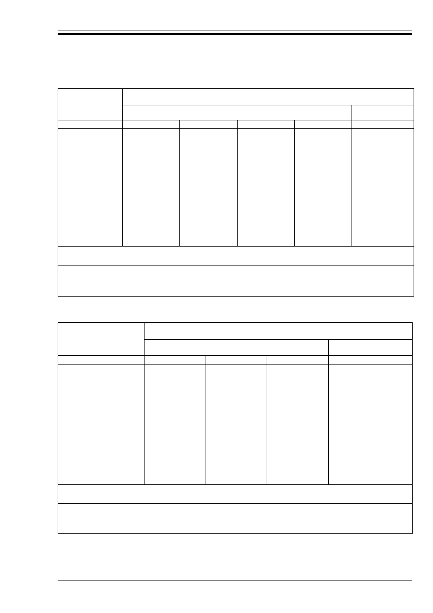
Table N4.1 — Minimum dimensions and axis distances for reinforced concrete
columns; rectangular and circular section
Reference in EC2-1.2
Definition
UK values
4.2.3
(4)
Limit to fire resistance for distribution bars along sides of columns 120 min.
4.2.7.4
(2)
Minimum top reinforcement over span in column strip
10 %
Standard fire resistance
Minimum dimensions
mm
Column width
b
min
/axis distance
a
Column exposed on more than one side
Exposed on one side
È
fi
= 0.2
È
fi
= 0.5
È
fi
= 0.7
È
fi
= 0.7
1
2
3
4
5
R 30
R 60
R 90
R 120
R 180
R 240
150/10
a
150/10
a
180/10
a
200/40
240/50
300/50
150/10
a
180/10
a
210/10
a
250/40
320/50
400/50
150/10
a
200/10
a
240/35
280/40
360/50
450/50
100/10
a
120/10
a
140/10
a
160/45
200/60
300/60
a
Normally the cover required by ENV 1992-1-1 will control.
Licensed copy:Heriot Watt University, 20/04/2004, Uncontrolled Copy, © BSI

DD ENV 1992-1-2:1996
vi
© BSI 03-2000
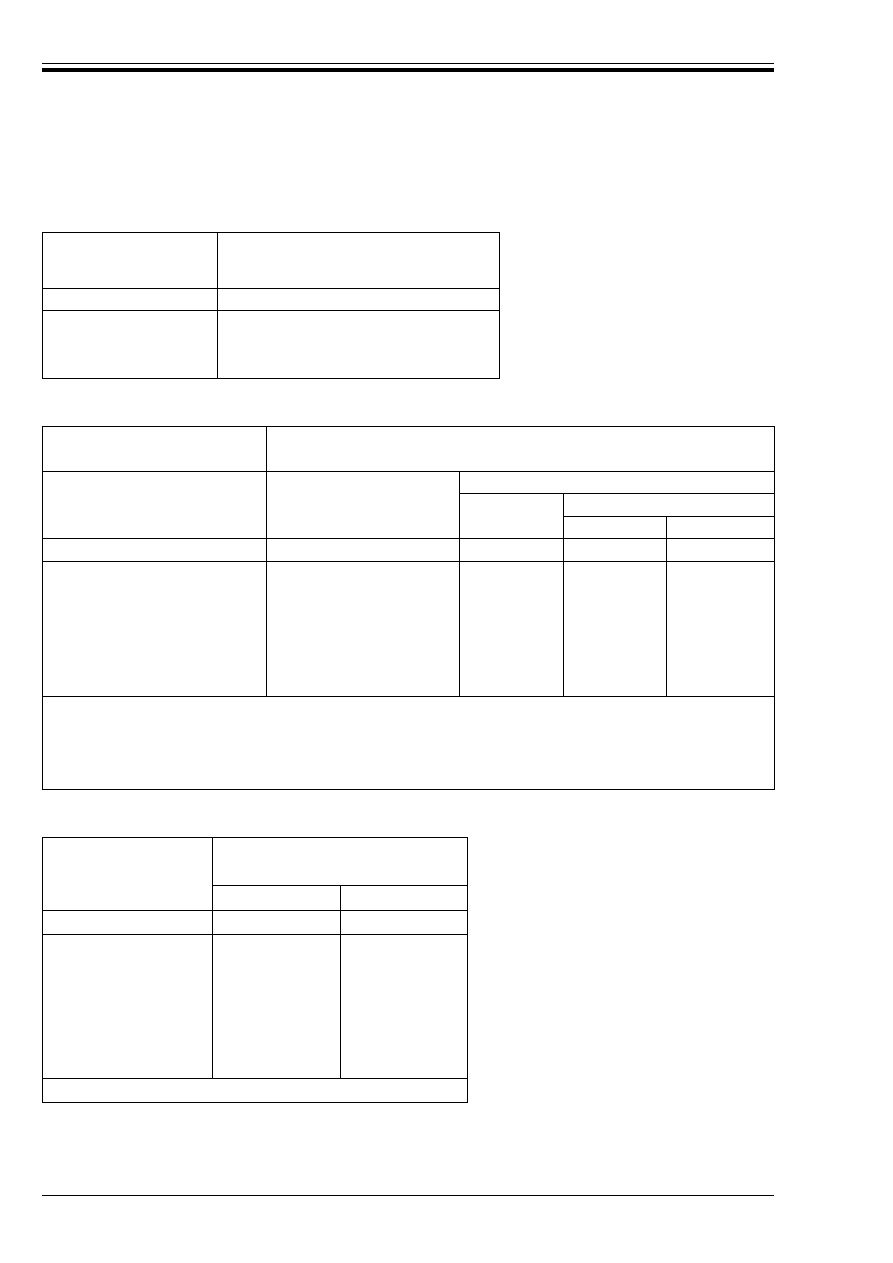
Table N4.2 — Minimum wall thickness
of non load-bearing walls (partitions)
Table N4.3 — Minimum dimensions and axis distances for load-bearing
reinforced concrete walls
Table N4.4 — Minimum dimensions and axis
distances for reinforced and prestressed
concrete tensile members
Standard fire resistance
Minimum wall thickness
mm
1
2
EI 30
EI 60
EI 90
EI 120
EI 180
EI 240
60
80
100
120
150
175
Standard fire
resistance
Minimum dimensions
mm
Wall thickness/axis distance for
È
f
= 0.35
È
f
= 0.7
Wall exposed on one
side
Wall exposed on two
sides
Wall exposed on one
side
Wall exposed on two
sides
1
2
3
4
5
REI 30
REI 60
REI 90
REI 120
REI 180
REI 240
100/10
a
110/10
a
120/20
a
150/25
180/35
230/45
120/10
a
120/10
a
140/10
a
160/25
200/35
250/45
120/10
a
130/10
a
140/25
160/35
210/45
270/55
120/10
a
140/10
a
170/25
220/35
250/45
300/55
a
Normally the cover required by ENV 1992-1-1 will control.
Standard fire
resistance
Minimum dimensions
mm
Possible combinations of member width
b
min
/axis
distance
a
1
2
3
R 30
R 60
R 90
R 120
R 180
R 240
80/25
120/40
150/55
200/65
240/80
280/90
200/10
a
300/25
400/45
500/45
600/60
700/70
NOTE For prestressed members the increase of axis distance according
to 4.2.2(4) should be noted.
a
Normally the cover required by ENV 1992-1-1 will control.
Licensed copy:Heriot Watt University, 20/04/2004, Uncontrolled Copy, © BSI
DD ENV 1992-1-2:1996
© BSI 03-2000
vii
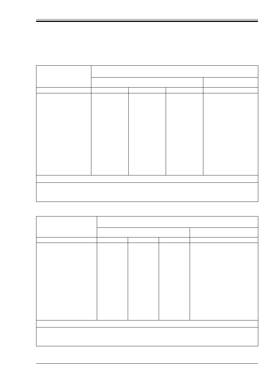
Table N4.5 — Minimum dimensions and axis distances for simply supported beams
made with reinforced and prestressed concrete
Table N4.6 — Minimum dimensions and axis distances for continuous beams
made with reinforced and prestressed concrete
Standard fire
resistance
Minimum dimensions
mm
Possible combinations of
a and b
min
where a is the average axis
distance and
b
min
is the width of beam
Web thickness
b
w
1
2
3
4
5
6
R 30
b
min
80
120
160
200
80
a
25
15
a
10
a
10
a
R 60
b
min
120
160
200
300
100
a
40
35
30
25
R 90
b
min
150
200
250
400
100
a
55
45
40
35
R 120
b
min
200
240
300
500
120
a
65
55
50
45
R 180
b
min
240
300
400
600
140
a
80
70
65
60
R 240
b
min
280
350
500
500
160
a
90
80
75
70
a
sd
= a + 10 mm
(see note 2.)
NOTE 1 For prestressed beams the increase of axis distance according to 4.2.2(4) of this Part 1-2 should be noted.
NOTE 2 a
sd
is the axis distance to the side of beam for the corner bars (tendon or wire) of beams with only one layer of
reinforcement. For values of b
min
greater than that given in column 4 no increase of a is required.
a
Normally the cover required by ENV 1992-1-1 will control.
Standard fire resistance
Minimum dimensions
mm
Possible combinations of
a and b
min
where a is the average
axis distance and
b
min
is the width of beam
Web thickness
b
w
1
2
3
4
5
R 30
b
min
80
160
200
80
a
12
a
12
a
12
a
R 60
b
min
120
200
300
100
a
25
12
a
12
a
R 90
b
min
150
250
400
100
a
35
25
25
R 120
b
min
180
300
450
120
a 55
45
35
R 180
b
min
225
350
550
140
a 70
60
50
R 240
b
min
275
450
650
160
a 80
70
60
a
sd
= a + 10 mm
(see note 2.)
NOTE 1 For prestressed beams the increase of axis distance according to 4.2.2(4) should be noted.
NOTE 2 a
sd
is the axis distance to the side of beam for the corner bars (tendon or wire) of beams with only one layer of
reinforcement. For values of b
min
greater than that given in column 3 no increase of a is required.
a
Normally the cover required by ENV 1992-1-1 will control.
Licensed copy:Heriot Watt University, 20/04/2004, Uncontrolled Copy, © BSI
DD ENV 1992-1-2:1996
viii
© BSI 03-2000
Table N4.7 — Reinforced and prestressed concrete
continuous I beams: increased beam width and web
thickness for conditions according to
Table N4.6
Table N4.8 — Minimum dimensions and axis distances for reinforced and
prestressed concrete simply supported one-way and two-way slabs
Table N4.9 — Minimum dimensions and axis distances
for reinforced and prestressed concrete flat slabs
Standard fire resistance
Minimum beam width
b
min
and web
thickness
b
w
mm
1
2
R 120
220
R 180
380
R 240
480
Standard fire resistance
Minimum dimensions
mm
Slab thickness
h
s
mm
Average axis-distance
a
One way
Two way:
l
y
/l
x
u 1.5
1.5
u l
y
/l
x
u 2
1
2
3
4
5
REI 30
60
10
a
10
a
10
a
REI 60
80
20
10
a
15
a
REI 90
100
30
15
a
20
REI 120
120
40
20
25
REI 180
150
55
30
40
REI 240
175
65
40
50
NOTE 1 l
x
and l
y
are the spans of a two-way slab (two directions at right angles) where l
y
is the longer span
NOTE 2 The minimum cover of any bar should not be less than half of required average axis distance, a
m’
defined in 4.2.2.
NOTE 3 For prestressed slabs the increase of axis distance according to 4.2.2(4) should be noted.
NOTE 4 The axis distance, a, in columns 4 and 5 for two way slabs relate to slabs supported at all four edges. Otherwise, they
should be treated as one-way spanning slab.
a
Normally the cover required by ENV 1992-1-1 will control.
Standard fire resistance
Minimum dimensions
mm
Slab thickness
h
s
Axis-distance
a
1
2
3
REI 30
75
10
a
REI 60
95
15
a
REI 90
110
25
REI 120
125
35
REI 180
150
45
REI 240
170
50
a
Normally the cover required by ENV 1992-1-1 will control.
Licensed copy:Heriot Watt University, 20/04/2004, Uncontrolled Copy, © BSI
DD ENV 1992-1-2:1996
© BSI 03-2000
ix
Table N4.10 — Minimum dimensions and axis distance for two-way spanning, simply
supported ribbed slabs in reinforced or prestressed concrete
Table N4.11 — Minimum dimensions and axis distances for two way spanning ribbed
slabs in reinforced or prestressed concrete with at least one restrained edge
Standard fire resistance
Minimum dimensions
mm
Possible combinations of width of
ribs
b
min
and axis distance a
Slab thickness
h
s
and axis
distance
a, in span
1
2
3
4
5
REI 30
b
min
W 80
h
s
80
a
15
a
a
10
a
REI 60
b
min
100
120
W 200
h
s
80
a
35
25
15
a
a
10
a
REI 90
b
min
120
160
W 250
h
s
100
a
45
40
30
a
15
a
REI 120
b
min
140
190
W 300
h
s
120
a
60
55
40
a
20
REI 180
b
min
170
260
W 410
h
s
150
a
75
75
60
a
30
REI 240
b
min
200
350
W 500
h
s
175
a
90
75
70
a
40
a
sd
= a + 10 mm
NOTE 1 For prestressed ribbed slabs, the axis-distance a should be increased in accordance with 4.2.2(4)
NOTE 2 a
sd
denotes the distance measured between the axis of the reinforcement and the lateral surface of the
rib exposed to fire.
a
Normally the cover required by ENV 1992-1-1 will control.
Standard fire resistance
Minimum dimensions
mm
Possible combinations of width of ribs
b
min
and
axis distance
a
Slab thickness
h
s
and axis distance
a, in span
1
2
3
4
5
REI 30
b
min
W 80
h
s
80
a
10
a
a
10
a
REI 60
b
min
100
120
W 200
h
s
80
a
25
15
a
10
a
a
10
a
REI 90
b
min
120
160
W 250
h
s
100
a
35
25
15
a
a
15
a
REI 120
b
min
140
190
W 300
h
s
120
a
45
40
30
a
20
REI 180
b
min
175
300
W 400
h
s
150
a
60
50
40
a
30
REI 240
b
min
200
400
W 500
h
s
175
a
70
60
50
a
40
a
sd
= a + 10 mm
NOTE 1 For prestressed ribbed slabs, the axis-distance a should be increased in accordance with 4.2.2(4).
NOTE 2 a
sd
denotes the distance measured between the axis of the reinforcement and the lateral surface of the
rib exposed to fire.
a
Normally the cover required by ENV 1992-1-1 will control.
Licensed copy:Heriot Watt University, 20/04/2004, Uncontrolled Copy, © BSI

DD ENV 1992-1-2:1996
x
© BSI 03-2000
4 Reference standards
Supporting standards including materials specifications and standards for construction are listed in
Table 2 of this NAD.
Table 2 — Reference in EC2 Part 1.2 to other codes and standards
5 Additional recommendations
5.1 Chapter 4. Structural fire design
a) Clause 4.2.2(4)
Current British practice assumes a less conservative increase in axis distance, a, from that given in
this clause. The second sentence onwards of this clause may be replaced with the following:
If no special check according to (4) is made in prestressed tensile members and beams the required axis
distance, a, should be increased by:
10 mm for prestressing bars, corresponding to Û
cr
= 400 °C;
15 mm for prestressing wires and strands, corresponding to Û
cr
= 350 °C.
If no special check according to (4) is made in prestressed simply supported slabs (including simply
supported ribbed slabs) the required axis distance, a, may be increased by 5 mm for prestressing bars,
wires and strands.
If no special check according to (4) is made in prestressed continuous slabs (including continuous ribbed
slabs) the required axis distance, a, should be increased by:
5 mm for prestressing bars;
10 mm for prestressing wires and strands.
b) Clause 4.2.2(14)
Current British practice assumes a less conservative increase in axis distance, a, from that given in
this clause. The value of %a
p
in equation (4.6) may be assumed as follows:
c) Clause 4.2.7.1(4) — addition
The effective thickness, h
e
, of hollow concrete slabs should be obtained by considering the total solid
part of the cross-section area as follows:
h
e
= h
1
. M
0.7
(4.12A)
where
Reference in EC2-1.2
Document
referred to
Subject area
Status
Various
ENV 1992-1-1
Design of concrete structures. General rules
and rules for buildings
Published 1991
Various
ENV 1991-2-1
Thermal and mechanical actions
Published 1995
1.1
(1)P 2.4.3(4)
ENV 1991-2-2
Design for accidental situation of fire exposure Published 1995
1.3
(1)
ISO 834
Standards for fire tests
Published 1975
1.4.12
ENV 1991-1
Fundamental combination of actions
Published 1994
4.2.4.2
(2)
ENV 1992-1-6
Minimum thickness of plain concrete walls
Published 1994
%a
p
= 5 mm for prestressing bars;
= 15 mm for prestressing wires and strands.
h
1
is the total thickness of concrete slab (See Figure 4.7 of EC2-1.2);
M
is the proportion of concrete cross section area to the total cross section area of
concrete slab including voids.
Licensed copy:Heriot Watt University, 20/04/2004, Uncontrolled Copy, © BSI

EUROPEAN PRESTANDARD
PRÉNORME EUROPÉENNE
EUROPÄISCHE VORNORM
ENV 1992-1-2:1995
November 1995
ICS 91.040.00; 91.080.40
Descriptors: Buildings, concrete structure, design, computation, fire resistance
English version
Eurocode 2: Design of concrete structures —
Part 1-2: General rules — Structural fire design
Eurocode 2: Calcul des structures en béton —
Partie 1-2: Règles générales — Calcul du
comportement au feu
Eurocode 2: Planung von Stahlbeton- und
Spannbetontragwerken — Teil 1-2: Allgemeine
Regeln — Tragwerksbemessung für den
Brandfall
This European Prestandard (ENV) was approved by CEN on 1994-01-14 as a
prospective standard for provisional application. The period of validity of this
ENV is limited initially to three years. After two years the members of CEN
will be requested to submit their comments, particularly on the question
whether the ENV can be converted into an European Standard (EN).
CEN members are required to announce the existence of this ENV in the same
way as for an EN and to make the ENV available promptly at national level in
an appropriate form. It is permissible to keep conflicting national standards in
force (in parallel to the ENV) until the final decision about the possible
conversion of the ENV into an EN is reached.
CEN members are the national standards bodies of Austria, Belgium,
Denmark, Finland, France, Germany, Greece, Iceland, Ireland, Italy,
Luxembourg, Netherlands, Norway, Portugal, Spain, Sweden, Switzerland and
United Kingdom.
CEN
European Committee for Standardization
Comité Européen de Normalisation
Europäisches Komitee für Normung
Central Secretariat: rue de Stassart 36, B-1050 Brussels
© 1995 All rights of reproduction and communication in any form and by any means reserved in all
countries to CEN and its members
Ref. No. ENV 1992-1-2:1995 E
Licensed copy:Heriot Watt University, 20/04/2004, Uncontrolled Copy, © BSI

ENV 1992-1-2:1995
© BSI 03-2000
2
Foreword
Objectives of the Eurocodes
(1) The “Structural Eurocodes” comprise a group of
standards for the structural and geotechnical design
of buildings and civil engineering works.
(2) They cover execution and control only to the
extent that is necessary to indicate the quality of the
construction products, and the standard of the
workmanship needed to comply with the
assumptions of the design rules.
(3) Until the necessary set of harmonized technical
specifications for products and for the methods of
testing their performance are available, some of the
Structural Eurocodes cover some of these aspects in
informative Annexes.
Background of the Eurocode program
(4) The Commission of the European Communities
(CEC) initiated the work of establishing a set of
harmonized technical rules for the design of
building and civil engineering works which would
initially serve as an alternative to the different rules
in force in the various Member States and would
ultimately replace them. These technical rules
became known as the “Structural Eurocodes”.
(5) In 1990, after consulting their respective
Member States, the CEC transferred the work of
further development, issue and updating of the
Structural Eurocodes to CEN, and the EFTA
Secretariat agreed to support the CEN work.
(6) CEN Technical Committee CEN/TC250 is
responsible for all Structural Eurocodes.
Eurocode program
(7) Work is in hand on the following Structural
Eurocodes, each generally consisting of a number of
parts:
EN 1991, Eurocode 1: Basis of design and actions
on structures.
EN 1992, Eurocode 2: Design of concrete
structures.
EN 1993, Eurocode 3: Design of steel structures.
EN 1994, Eurocode 4: Design of composite steel
and concrete structures.
EN 1995, Eurocode 5: Design of timber
structures.
EN 1996, Eurocode 6: Design of masonry
structures.
EN 1997, Eurocode 7: Geotechnical design.
EN 1998, Eurocode 8: Design provisions for
earthquake resistance of structures.
EN 1999, Eurocode 9: Design of aluminium alloy
structures.
(8) Separate subcommittees have been formed by
CEN/TC250 for the various Eurocodes listed above.
(9) This Part 1-2 of Eurocode 2 is being published as
a European Prestandard (ENV) with an initial life of
three years.
(10) This Prestandard is intended for experimental
application and for the submission of comments.
(11) After approximately two years CEN members
will be invited to submit formal comments to be
taken into account in determining future actions.
(12) Meanwhile feedback and comments on this
Prestandard should be sent to the Secretariat of
CEN/TC250/SC2 at the following address:
Deutsches Institut für Normung e.V. (DIN)
Burggrafenstrasse 6
D-10787 Berlin
Phone:(+49) 30 2601 2501
Fax:(+49) 30 2601 1231
or to your national standards organisation
National Application Documents (NAD’S)
(13) In view of the responsibilities of authorities in
member countries for safety, health and other
matters covered by the essential requirements of
the Construction Products Directive (CPD), certain
safety elements in this ENV have been assigned
indicative values which are identified by|_|(“boxed
values”). The authorities in each member country
are expected to assign definitive values to these
safety elements.
(14) Some of the supporting European or
International Standards may not be available by
the time this Prestandard is issued. It is therefore
anticipated that a National Application Document
(NAD) giving definitive values for safety elements,
referencing compatible supporting standards and
providing national guidance on the application of
this Prestandard, will be issued by each member
country or its Standards Organisation.
(15) It is intended that this Prestandard is used in
conjunction with the NAD valid in the country
where the building or civil engineering works is
located.
Matters specific to this prestandard
(16) The scope of Eurocode 2 is defined in 1.1.1 of
ENV 1992-1-1 and the scope of this Part of
Eurocode 2 is defined in 1.1. Additional Parts of
Eurocode 2 which are planned are indicated in 1.1.3
of ENV 1992-1-1; these will cover additional
technologies or applications, and will complement
and supplement this Part.
Licensed copy:Heriot Watt University, 20/04/2004, Uncontrolled Copy, © BSI

ENV 1992-1-2:1995
© BSI 03-2000
3
(17) In using this Prestandard in practice,
particular regard should be paid to the underlying
assumptions and conditions given in 1.3 of
ENV 1992-1-1.
(18) The provisions of this Prestandard are based
substantially on recent CEB and FIP documents.
(19) This Part 1-2 of Eurocode 2 complements
ENV 1992-1-1 for the particular aspects of
structural fire design of concrete structures. The
provisions in this Part 1-2 have to be considered
additionally to those in other Parts of ENV 1992.
(20) The framework and structure of this Part 1-2 do
not correspond to ENV 1992-1-1.
(21) This Part 1-2 contains five sections and four
informative Annexes. These Annexes have been
introduced by moving some of the more detailed
Application Rules, which are needed in particular
cases, out of the main part of the text to aid its
clarity.
(22) Required functions and levels of performance
are generally specified by the National
Authorities — mostly in terms of standard fire
resistance rating. Where fire safety engineering for
assessing passive and active measures is accepted,
requirements by authorities will be less prescriptive
and may allow for alternative strategies.
Licensed copy:Heriot Watt University, 20/04/2004, Uncontrolled Copy, © BSI

ENV 1992-1-2:1995
4
© BSI 03-2000
Contents
Page
Foreword
2
1
General
7
1.1
Scope
7
1.2
Distinction between principles
and application rules
7
1.3
Normative References
7
1.4
Definitions
7
1.5
Symbols
10
1.6
Units
10
2
Basic principles
11
2.1
Performance requirements
11
2.2
Actions
11
2.3
Design values of material properties
11
2.4
Verification methods
12
2.4.1 General
12
2.4.2 Global structural analysis
12
2.4.3 Analysis of parts of the structure
12
2.4.4 Member analysis
13
2.4.5 Testing
13
3
Material properties
14
3.1
General
14
3.2
Concrete
14
3.3
Steel
14
4
Structural fire design
17
4.1
General
17
4.2
Tabulated data
17
4.2.1 Scope
17
4.2.2 General design rules
18
4.2.3 Columns
20
4.2.4 Walls
21
4.2.5 Tensile members
22
4.2.6 Beams
23
4.2.7 Slabs
27
4.3
Simplified calculation method
31
4.3.1 General
31
4.3.2 Temperature profiles
32
4.3.3 Reduced cross section
32
4.4
General calculation methods
35
4.4.1 General
35
4.4.2 Thermal response
35
4.4.3 Mechanical response
35
4.4.4 Validation of general calculation method 36
4.5
Shear and torsion
36
Page
4.6
Anchorage
36
5
Protective layers
37
Annex A (informative) Additional
information on material properties
38
Annex B (informative) Temperature
profiles and reduced cross section
54
Annex C (informative) Simplified method
of calculation for beams and slabs
58
Annex D (informative) A procedure for
assessing the structural response of
reinforced concrete elements under fire
59
Figure 2.1 — Variation of ½
fi
as a function
of ß = Q
k1
/G
k
for different values of Ó
1,1
13
Figure 3.1 — Coefficient k
c
(G) allowing
for decrease of compressive strength (f
ck
)
of silicious concrete at elevated temperature
15
Figure 3.2 — Coefficient k
s
(G) allowing for
decrease of characteristic strength (f
yk
) of
reinforcing steels at elevated
temperature
16
Figure 3.3 — Coefficient k
p
(G) allowing
for decrease of characteristic strength (f
pk
)
of prestressing steels at elevated
temperature
16
Figure 4.1 — Sections through
structural members, showing nominal
axis distance a, and nominal concrete
cover c to reinforcement
19
Figure 4.2 — Dimensions used to
calculate average axis distance a
m
19
Figure 4.3 — Exposure of built-in columns
21
Figure 4.4 — Definition of dimensions
for different types of beam section
23
Figure 4.5 —
I
-shaped beam with increasing
web width b
w
satisfying the requirements
of an imaginary cross-section
24
Figure 4.6 — Envelope of resisting bending
moments over supports in fire conditions
25
Figure 4.7 — Concrete slab with floor finishes
27
Figure 4.8 — Slab systems for which minimum
reinforcement areas according to 4.2.7.3 (3)
should be provided
29
Figure 4.9 — Reductions of strength and
cross-sections found by means of
equivalent walls (wall1 and wall2) exposed
to fire on both sides
33
Figure 4.10 — Divisions of a wall, exposed
on both sides, into zones for use in
calculation of strength reduction
and a
z
values
34
Licensed copy:Heriot Watt University, 20/04/2004, Uncontrolled Copy, © BSI

ENV 1992-1-2:1995
© BSI 03-2000
5
Page
Figure A.1 — Coefficient k
ct
(G) allowing
for decrease of tensile strength, (f
ctk
) of
concrete at elevated temperature
38
Figure A.2 — Model for compression
stress-strain relationships of siliceous
and calcareous concrete at elevated
temperatures
39
Figure A.3 — Parameters for stress-strain
relationships of concrete at elevated
temperatures, according to Figure A.2
and Table A.1
40
Figure A.4 — Stress-strain relationships
of siliceous concrete under uniaxial
compression at elevated temperatures
41
Figure A.5 — Model for stress-strain
relationships of reinforcing and prestressing
steels at elevated temperatures (notations
for prestressing steels “p” instead of “s”)
42
Figure A.6 — Stress-strain relationships of
hot-rolled reinforcing steels at elevated
temperatures, according to Figure A.5
and Table A.3
45
Figure A.7 — Parameters for stress-strain
relationships of hot-rolled reinforcing
steels at elevated temperatures, according
to Figure A.5 and Table A.3
45
Figure A.8 — Stress-strain relationships
for cold-worked reinforcing steels at
elevated temperatures, according to
Figure A.5 and Table A.4
46
Figure A.9 — Parameters for stress-strain
relationships of cold-worked reinforcing
steels at elevated temperatures,
according to Figure A.5 and Table A.4
47
Figure A.10 — Stress-strain relationships
for quenched and tempered prestressing
steels (bars) at elevated temperatures,
according to Figure A.5 and Table A.5
47
Figure A.11 — Parameters for
stress-strain relationships of quenched
and tempered prestressing steels (bars) at
elevated temperatures, according to Figure A.5;
and Table A.5
48
Figure A.12 — Stress-strain relationships
for cold-worked prestressing steels (wires
and strands) at elevated temperatures,
according to Figure A.5 and Table A.6
48
Figure A.13 — Parameters for stress-strain
relationships of cold-worked prestressing
steels (wires and strands) at elevated
temperatures, according to Figure A.5
and Table A.6
49
Page
Figure A.14 — Thermal elongation of concrete
50
Figure A.15 — Specific heat of concrete
51
Figure A.16 — Thermal conductivity of concrete 51
Figure A.17 — Thermal elongation of steel
53
Figure A.18 — Relationship between Ö
c,fi
and h (or b) for risk of explosive spalling
for normal weight concrete members
54
Figure B.1 — Temperature profiles for beams
55
Figure B.2 — Temperature profiles for slabs
56
Figure B.3 — Reduction in cross section and
concrete strength assuming a standard fire
57
Figure C.1 — Positioning the free bending
moment diagram M
Sd,fi
to establish equilibrium 59
Figure D.1 — Temperature profiles in concrete
elements. G
m
is the average temperature
along a horizontal section y-y
60
Figure D.2 — Layers of thermo-elements
assumed free to move axially
60
Figure D.3 — Hypothetical and equalising
forces
61
Figure D.4 — Final internal self-equilibrating
stresses
62
Figure D.5 — Equivalent temperature
values G
eff
for typical reinforced concrete
sections exposed to a standard fire
63
Table 4.1 — Minimum dimensions and
axis distances for reinforced concrete
columns; rectangular and circular section
21
Table 4.2 — Minimum wall thickness of
non load-bearing walls (partitions)
22
Table 4.3 — Minimum dimensions and
axis distances for load-bearing reinforced
concrete walls
22
Table 4.4 — Minimum dimensions and axis
distances for reinforced and prestressed
concrete tensile members
23
Table 4.5 — Minimum dimensions and axis
distances for simply supported beams
made with reinforced and prestressed concrete 26
Table 4.6 — Minimum dimensions and axis
distances for continuous beams made with
reinforced and prestressed concrete
26
Table 4.7 — Reinforced and prestressed
concrete continuous
I
-beams; increased
beam width and web thickness for
conditions according to 4.2.6.3 (6)
27
Table 4.8 — Minimum dimensions and axis
distances for reinforced and prestressed
concrete simply supported one-way
and two-way slabs
28
Licensed copy:Heriot Watt University, 20/04/2004, Uncontrolled Copy, © BSI

ENV 1992-1-2:1995
6
© BSI 03-2000
Page
Table 4.9 — Minimum dimensions and
axis distances for reinforced and
prestressed concrete flat slabs
29
Table 4.10 — Minimum dimensions and
axis distance for two-way spanning, simply
supported ribbed slabs in reinforced or
prestressed concrete
30
Table 4.11 — Minimum dimensions and
axis distances for two-way spanning ribbed
slabs in reinforced or prestressed concrete
with at least one restrained edge
31
Table A.1 — Values for the main parameters
of the stress-strain relationships in
compression of siliceous and calcareous
concrete at elevated temperatures
(range I in Figure A.2)
39
Table A.2 — Recommended values
for º
c1
(G) and º
cu
(G) and admissible range
of º
c1
(G)
41
Table A.3 — Values for the parameters
of the stress-strain relationship of hot
rolled reinforcing steel
43
Table A.4 — Values for the parameters
of the stress-strain relationship of cold
worked reinforcing steel
43
Table A.5 — Values for the parameters
of the stress-strain relationship of
quenched and tempered prestressing steel
44
Table A.6 — Values for the parameters
of the stress-strain relationship of cold
worked prestressing steel
44
Licensed copy:Heriot Watt University, 20/04/2004, Uncontrolled Copy, © BSI

ENV 1992-1-2:1995
© BSI 03-2000
7
1 General
1.1 Scope
(1)P ENV 1992-1-2 deals with the design of concrete structures for the accidental situation of fire exposure
and shall be used in conjunction with ENV 1992-1-1 and ENV 1991-2-2. It provides additions to and
identifies differences from the design of structures at normal temperatures.
(2)P Part 1-2 applies only to passive methods of fire protection. Active methods are not included.
(3)P Part 1-2 applies to structures which for reasons of general fire safety, are required to fulfil the
following criteria when exposed to fire:
— avoid premature collapse of the structure (load-bearing function)
— limit fire spread (flames, hot gases, excessive heat) beyond designated areas (separation function)
(4)P Part 1-2 gives Principles and Application Rules (see 1.2 in ENV 1992-1-1) in respect to the design of
structures to fulfil the criteria given in (3)P (e.g. in terms of required standard fire resistance).
(5)P Part 1-2 applies to those structures or parts of structures which are within the scope of Part 1-1, 1-3
to 1-6. However, it does not cover:
— structures with prestressing by external tendons
— shell structures.
(6) For structures using unbonded tendons reference should be made to 4.1(6) and 4.2.2(6).
1.2 Distinction between principles and application rules
(1) Depending on the character of the individual clauses, distinction is made in this Part between principles
and application rules.
(2) The principles comprise:
— general statements and definitions for which there is no alternative, as well as
— requirements and analytical models for which no alternative is permitted unless specifically stated.
(3) The principles are identified by the letter P following the paragraph number.
(4) The application rules are generally recognized rules which follow the principles and satisfy their
requirements.
(5) It is permissible to use alternative rules different from the application rules given in this Eurocode,
provided it is shown that the alternative rules accord with the relevant principles and have at least the
same reliability.
(6) In this Part the application rules are identified by a number in brackets eg. as this clause.
1.3 Normative references
(1) European standards for fire tests are under preparation. In National Application Documents reference
may be made to national or International Standards. For structural members ISO 834 is generally used.
1.4 Definitions
1.4.1
critical temperature of reinforcement
the temperature at which failure is expected to occur in reinforcement at a given load level
1.4.2
design fire
a specified fire development assumed for design purposes
1.4.3
effects of actions E
(as described in ENV 1992-1-1, 2.2.2.5)
the effects of actions (E) are responses (for example internal forces and moments, stresses, strains) of the
structure to the actions
Licensed copy:Heriot Watt University, 20/04/2004, Uncontrolled Copy, © BSI

ENV 1992-1-2:1995
8
© BSI 03-2000
1.4.4
fire compartment
a space within a building extending over one or several floors which is enclosed by separating members
such, that fire spread beyond the compartment is prevented during the relevant fire exposure
1.4.5
fire resistance
the ability of a structure or part of it to fulfil its required functions (load-bearing and/or separating
function) for a specified fire exposure, for a specified period of time
1.4.6
global structural analysis
(for fire)
the analysis of the entire structure, when either the entire structure or only parts of it are exposed to fire.
Indirect fire actions are considered throughout the structure
1.4.7
indirect fire actions
thermal expansions or thermal deformations causing forces and moments
1.4.8
integrity criterion “E”
a criterion by which the ability of a separating member to prevent passage of flames and hot gases is
assessed
1.4.9
load-bearing criterion “R”
a criterion by which the ability of a structure or a member to sustain specified actions during the relevant
fire, is assessed
1.4.10
load-bearing function
the ability of a structure or member to sustain specified actions during the relevant fire
1.4.11
member analysis
(for fire)
the thermal and mechanical analysis of a structural member exposed to fire in which the member is
considered as isolated with appropriate support and boundary conditions. Indirect fire actions are not
considered, apart from those resulting from thermal gradients
1.4.12
normal temperature design
ultimate limit state design for ambient temperatures according to ENV 1992-1-1 for the fundamental
combination of actions (see ENV 1991-1)
1.4.13
protected members
members for which measures are taken to reduce the temperature rise in the member due to fire
1.4.14
separating function
the ability of a separating member to prevent fire spread by passage of flames or hot gases (integrity) or
ignition beyond the exposed surface (thermal insulation) during the relevant fire
1.4.15
separating members
structural and non-structural members (walls or floors) forming the enclosure of a fire compartment
Licensed copy:Heriot Watt University, 20/04/2004, Uncontrolled Copy, © BSI

ENV 1992-1-2:1995
© BSI 03-2000
9
1.4.16
standard fire resistance
the ability of a structure or part of it (usually only members) to fulfil required functions (load-bearing
function and/or separating function) for exposure to heating according to the standard temperature-time
curve, for a stated period of time
1.4.17
structural members
the load-bearing members of a structure including bracings
1.4.18
sub-assembly analysis
(for fire)
the structural analysis of parts of the structure exposed to fire in which the respective part of the structure
is considered as isolated with appropriate support and boundary conditions. Indirect fire actions within the
sub-assembly are considered, but time-dependent interaction with other parts of the structure is not
considered
NOTE 1 Where the effects of indirect fire actions within the sub-assembly are negligible, sub-assembly analysis is equivalent to
member analysis.
NOTE 2 Where the effects of indirect fire actions between sub-assemblies are negligible, sub-assembly analysis is equivalent to
global structural analysis.
1.4.19
support and boundary conditions
description of restraints at supports and boundaries for structural modelling
1.4.20
temperature analysis
the procedure to determine the temperature development in members on the basis of thermal actions and
the thermal material properties of the members and of the protective layers, where relevant
1.4.21
temperature-time curves
gas temperatures in the environment of member surfaces as a function of time. They may be either
— Nominal: Conventional curves, adopted for classification or verification of fire resistance, e.g. the
standard temperature-time curve.
— Parametric: Determined on the basis of fire models and the specific physical parameters defining the
conditions in the fire compartment.
1.4.22
thermal actions
actions on the structure described by the net heat flux to the members
1.4.23
thermal insulation criterion “I”
a criterion by which the ability of a separating member to prevent excessive transmission of heat is
assessed
Licensed copy:Heriot Watt University, 20/04/2004, Uncontrolled Copy, © BSI

ENV 1992-1-2:1995
10
© BSI 03-2000
1.5 Symbols
The following symbols supplement those given in ENV 1992-1-1:
1.6 Units
(1) Temperature G in degrees Celsius (°C)
Temperature difference in kelvins (K)
Specific heat c in joule per kilogramme per kelvin (J/kgK)
Coefficient of thermal conductivity Æ in watts per metre per kelvin (W/mK)
E
d,fi
design effect of actions in the fire situation
E
d
design effect of actions for normal temperature design
R
d,fi
design load bearing capacity (resistance) in the fire situation R
d,fi
(t) at a given time t.
R 30 or R 60,... a member meeting the load-bearing criterion for 30, or 60... minutes in standard fire
exposure
E 30 or E 60,... a member meeting the integrity criterion for 30, or 60... minutes in standard fire
exposure
I 30 or I 60,... a member meeting the thermal insulation criterion for 30, or 60... minutes in standard
fire exposure
X
k
characteristic value of a strength or deformation property for normal temperature design
X
d,fi
design strength or deformation property in the fire situation
a
axis distance of the steel from the nearest exposed surface
c
specific heat (characteristic value) [J/kgK]
f
ck
(G) characteristic value of compressive strength of concrete at temperature G for a specified strain
f
pk
(G) characteristic value of strength of prestressing steel at temperature G for a specified strain
f
sk
(G) characteristic strength of reinforcing steel at temperature G for a specified strain
k
(G) = X
k
,(G)/X
k
reduction factor to describe a strength or deformation property at temperature G
t
time of fire exposure (min)
Y
M,fi
partial safety factor for a material in fire design
½
fi
= E
d,fi
/E
d
ratio of design effect of actions in the fire situation to that in normal design
º
s,fi
strain of the reinforcing or prestressing steel at temperature G.
Æ
thermal conductivity (characteristic value) [W/mK]
È
fi
= E
d,fi
/R
d,fi
(0) ratio of design effect of actions in the fire situation to the design resistance of the
structural element at time t = 0
Ö
c,fi
compressive stress of concrete in fire situation
Ö
s,fi
steel stress in fire situation
G
temperature [°C]
G
cr
critical temperature [°C]
Licensed copy:Heriot Watt University, 20/04/2004, Uncontrolled Copy, © BSI

ENV 1992-1-2:1995
© BSI 03-2000
11
2 Basic principles
2.1 Performance requirements
(1)P Where structures are required to have mechanical resistance under fire conditions, they shall be
designed and constructed in such a way that they maintain their load bearing function during the relevant
fire exposure — Criterion “R”.
(2)P Where compartmentation is required, the members forming the compartment, including joints, shall
be designed and constructed in such a way that they maintain their separating function during the relevant
fire exposure, i.e.
— no integrity failure due to cracks, holes or other openings, which are large enough to cause fire
penetration by hot gases or flame — Criterion “E”
— no insulation failure due to temperatures of the non-exposed surface exceeding ignition temperatures
— Criterion “I”.
(3) Criterion “I” may be assumed to be met where the average temperature rise over the whole of the
non-exposed surface during the standard fire exposure does not exceed 140K and the maximum
temperature rise of that surface does not exceed 180K.
(4)P Members shall comply with criteria R, E and I as follows:
separating only: E and I
loadbearing only: R
separating and loadbearing: R, E and I
(5) When using general calculation methods (see 4.4) the deformation criteria should be used where
separating members or protective measures are affected by the deformation of the load bearing structure.
Reference should be made to the relevant product specifications.
2.2 Actions
(1)P Thermal and mechanical actions shall be obtained from ENV 1991-2-2.
(2) Where rules given in this Part 1-2 are only valid for the standard fire exposure, this is identified in the
relevant clauses.
2.3 Design values of material properties
(1)P Design values of thermal and mechanical properties (X
d,fi
) are defined as follows:
— thermal properties for thermal analysis
if an increase of the property is favourable for safety
if an increase of the property is unfavourable for safety
— strength and deformation properties for structural analysis
where
X
k
(G) is the characteristic value of a material property in fire design, generally dependent on the
material temperature
X
k
is the characteristic value of a strength or deformation property (e.g. f
ck
and f
yk
) for normal
temperature design to ENV 1992-1-1
k
(G) = X
k
(G)/X
k
is the reduction factor for a strength or deformation property dependent on the material
temperature — see 3.2 and 3.3
Y
M,fi
is the partial safety factor for material property in fire design
(2) For thermal and mechanical properties of concrete and steel reinforcement the partial safety factor for
fire design should be taken as
X
d,fi
= X
k
(G)/Y
M,fi
(2.1)
X
d,fi
= X
k
(G) Y
M,fi
(2.2)
X
d,fi
= k(G) X
k
/Y
M,fi
(2.3)
Licensed copy:Heriot Watt University, 20/04/2004, Uncontrolled Copy, © BSI

ENV 1992-1-2:1995
12
© BSI 03-2000
Y
M,fi
=|1,0|
2.4 Verification methods
2.4.1 General
(1)P The fire resistance of a concrete structure may be determined by any of the methods given
in 2.4.2 to 2.4.5.
(2) Tabulated data given in 4.2 are based on the standard temperature-time curve. The simplified and
general calculation methods may also be used with parametrical temperature-time relationship,
see ENV 1991-2-2.
2.4.2 Global structural analysis
(1)P For the global structural analysis, it shall be verified that
where
E
d,fi
(t) is the design effect of actions in the fire situation, determined from the general rule given in
ENV 1991-2-2, including indirect fire actions
R
d,fi
(t) is the corresponding design resistance at elevated temperatures
t
is the relevant duration of fire exposure
(2)P The structural model adopted for design to this ENV 1992-1-2 shall reflect the expected performance
of the structure in fire exposure.
(3) The global structural analysis should take into account the relevant failure mode in fire exposure, the
temperature-dependent material properties including stiffness, and effects of thermal expansions and
deformations (indirect fire actions).
(4) General calculation methods given in 4.4 are suitable for global structural analysis. They are based on
models which determine the temperature development within the structure and the mechanical behaviour
of the structure.
2.4.3 Analysis of parts of the structure
(1) As an alternative to the global structural analysis of the entire structure for various fire situations, a
structural analysis of parts of the structure (sub-assemblies) may be performed, where the sub-assemblies
are exposed to fire and analyzed in accordance with 2.4.2
(2) Sub-assemblies should be specified on the basis of the potential thermal expansions and deformations
such, that their interaction with other parts of the structure can be approximated by time-independent
support and boundary conditions during fire exposure.
(3) Effects of (permanent and variable) actions at supports and boundaries may be assumed to correspond
to those in ENV 1992-1-1.
(4) As an approximation to performing a global structural analysis for t = 0, effects of (permanent and
variable) actions at supports and boundaries may be obtained from the normal temperature design by
using
where
Values of Ó
1,i
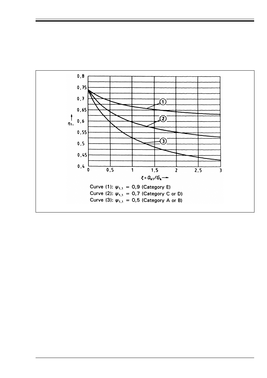
are given in ENV 1991-1. Equation (2.6) is graphically represented presented in Figure 2.1.
(5) As a simplification ½
fi
=|0,6|may be used, except for load category E as given in ENV 1991-2-1 (areas
susceptible to accumulation of goods, including access areas) for which a value of|0,7|should be used.
E
d,fi
(t) u R
d,fi
(t)
(2.4)
E
d,fi
= ½
fi
.E
d
(2.5)
E
d
is the design effect of actions from ultimate limit state design to ENV 1992-1-1 using the
fundamental combination
½
fi
is a reduction factor, depending on ß = Q
k1
/G
k
, which is the ratio between the main variable and
permanent actions applied to the structure, see ENV 1991-2-2:
½
fi
= ([1,0] + Ó
1,1
,ß)/(Y
G
+ Y
Q
.ß)
(2.6)
Licensed copy:Heriot Watt University, 20/04/2004, Uncontrolled Copy, © BSI
ENV 1992-1-2:1995
© BSI 03-2000
13
(6) Simplified and general methods given in 4.3 and 4.4 respectively are suitable for analysis of parts of the
structure.
2.4.4 Member analysis
(1) The support and boundary conditions of members corresponding to those in ENV 1992-1-1 may be used.
Where different conditions apply, they are identified in the relevant clauses.
(2) 2.4.3 (4) also applies to member analysis.
(3) The effects of thermal expansion need not, in general, be taken into account for member analysis.
(4) For verifying standard fire resistance requirements, member analysis is sufficient.
(5) Tabulated data, simplified or general methods given in 4.2, 4.3 and 4.4 respectively are suitable for
verifying members under fire conditions.
The tabulated data method consists of simple checks of dimensions of cross-sections and of axis distances
of the reinforcement. In some cases simple checks of the load level and additional detailing rules are also
required. When the actual steel stress and temperature are known more accurately, the values in the tables
may be modified.
2.4.5 Testing
(1) As an alternative to the use of calculation methods, fire design may be based on the results of tests.
(2) Combinations of testing and calculations may also be used.
Figure 2.1 — Variation of ½
fi
as a function of ß = Q
k1
/G
k
for different values of Ó
1,1
Licensed copy:Heriot Watt University, 20/04/2004, Uncontrolled Copy, © BSI

ENV 1992-1-2:1995
14
© BSI 03-2000
3 Material properties
3.1 General
(1)P In fire conditions the temperature dependent properties shall be taken into account.
(2) The material properties at 20 °C should be assessed according to ENV 1992-1-1.
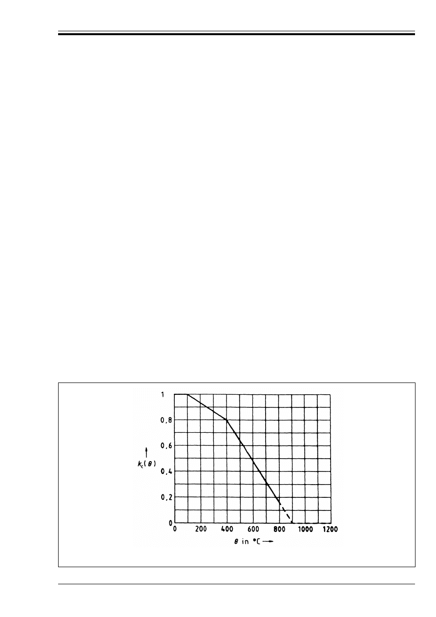
(3) Values for the reduction of the characteristic compressive strength of concrete, and of the characteristic
strength of reinforcing and prestressing steels are given in this section. They may be used with the
simplified calculation methods. These values may also be used for the evaluation of the critical temperature
of reinforcement when adapting tabulated data for critical temperatures other than 500 °C (see 4.2.2).
(4) Additional information on thermo-mechanical properties for general calculation methods is given in
Informative Annex A. Reference may also be made to appropriate documents.
(5) The material models given in 3.2 and 3.3 below should only be applied for heating rates similar to those
appearing under standard fire exposure until the time of the maximum temperature.
(6) Alternative formulations of material laws (e.g. for parametric fires) may be applied, provided solutions
are within the range of appropriate experimental evidence.
(7) The standard fire conditions are defined between 20 °C and 1 200 °C, the properties are also defined
between the same limits.
The values at the higher temperatures shown dashed in Figure 3.1, Figure 3.2 and Figure 3.3 are given as
indication only.
3.2 Concrete
(1) The reduction of the characteristic compressive strength of concrete as a function of the temperature G
is allowed for by the coefficient k
c
(G) for which:
(2) In the absence of more accurate information the following k
c
(G) values, applicable to concretes with
siliceous aggregates, should be used (see Figure 3.1).
They may be considered as conservative values for other types of concrete.
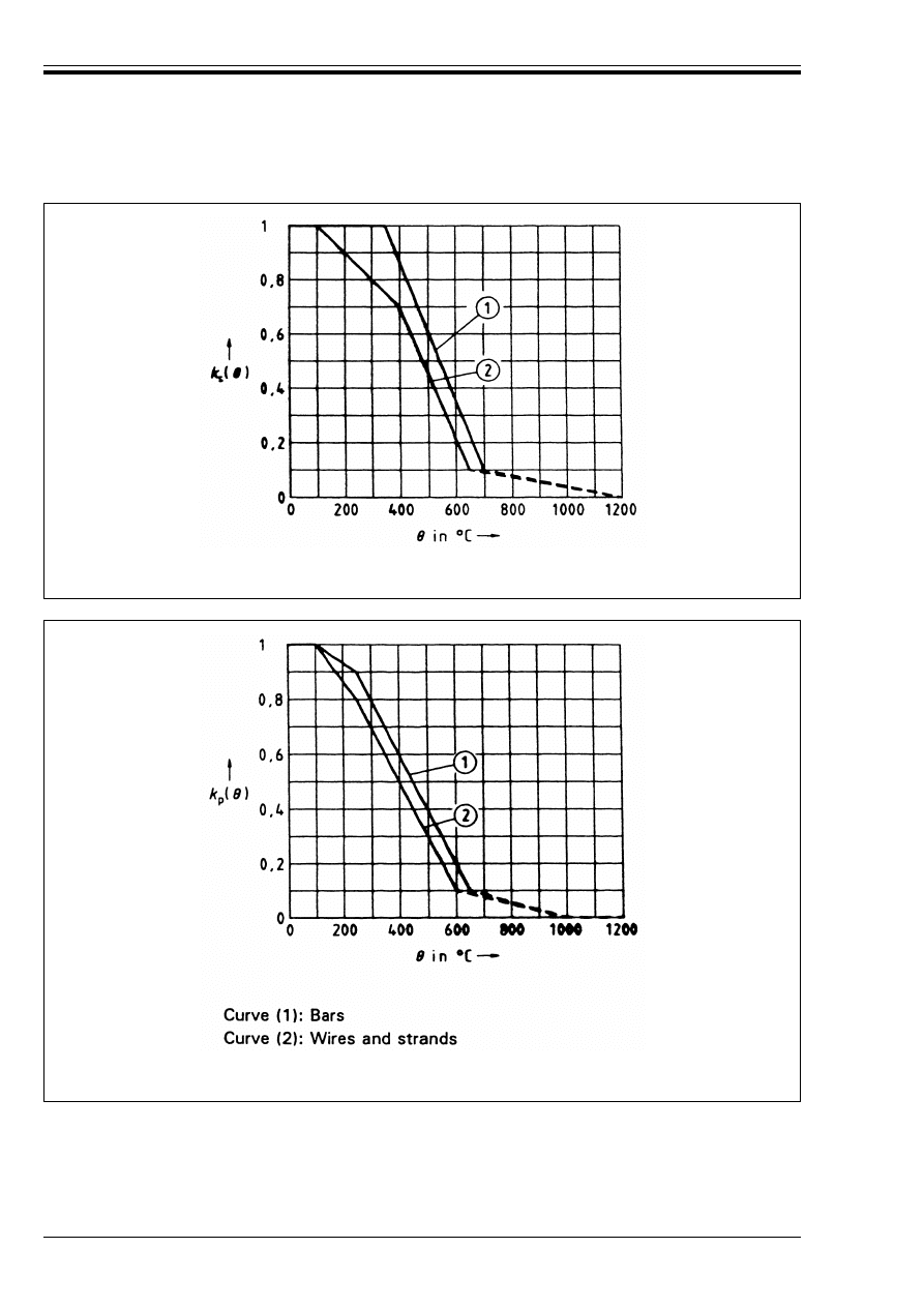
3.3 Steel
(1) The reduction of the characteristic strength of a reinforcing steel as a function of the temperature G is
allowed for by the coefficient k
s
(G) for which:
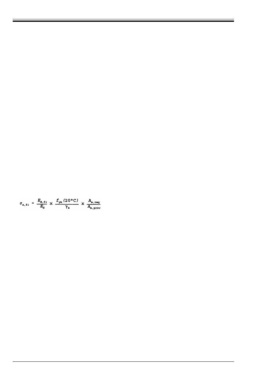
(2) The reduction of the characteristic strength of a prestressing steel as a function of the temperature G
is allowed for by the coefficient k
p
(G) for which:
(3) Where k
s
(G) and k
p
(G) are taken from documented data they should be derived from tests performed
under constant stress and variable temperature (transient tests).
(4)In the absence of more accurate information the following k
s
(G) values should be used for reinforcement
(see Figure 3.2).
f
ck
(G) = k
c
(G) f
ck
(20 °C)
(3.1)
k
c
(G) = 1,0
for 20 °C u G u 100 °C
k
c
(G) = (1 600 – G)/1 500
for 100 °C u G u 400 °C
k
c
(G) = (900 – G)/625
for 400 °C u G u 900 °C
k
c
(G) = 0
for 900 °C u G u 1 200 °C
f
sk
(G) = k
s
(G)f
yk
(20 °C)
(3.2)
f
pk
(G) = k
p
(G)f
pk
(20 °C)
(3.3)
Licensed copy:Heriot Watt University, 20/04/2004, Uncontrolled Copy, © BSI
ENV 1992-1-2:1995
© BSI 03-2000
15
For tension reinforcement in beams and slabs where º
s,fi
W 2 %, the strength reduction may be used as given
below (see Figure 3.2, Curve 1). This corresponds to the values given in the tables in 4.2.
For compression reinforcement in columns and compressive zones of beams and slabs the strength
reduction at 0,2 % proof strain should be used as given below (see Figure 3.2, Curve 2). This also applies
for tension reinforcement where º
s,fi
< 2 % when using the simplified or general calculation methods.
(5) In the absence of more accurate information the following k
p
(G) values should be used for prestressing
steel (see Figure 3.3).
For prestressing steel bars:
For prestressing steel wires and strands:
k
s
(G) = 1,0
for 20 °C u G u 350 °C
k
s
(G) = (6 650 – 9G)/3 500
for 350 °C u G u 700 °C
k
s
(G) = (1 200 – G)/5 000
for 700 °C u G u 1 200 °C
k
s
(G) = 1,0
for 20 °C u G u 100 °C
k
s
(G) = (1 100 – G)/1 000
for 100 °C u G u 400 °C
k
s
(G) = (8 300 – 12 G)/5 000
for 400 °C u G u 650 °C
k
s
(G) = (1 200 – G)/5 500
for 650 °C u G u 1 200 °C
k
p
(G) = 1,0
for 20 °C u G u 100 °C
k
p
(G) = (1 600 – G)/1 500
for 100 °C u G u 250 °C
k
p
(G) = (700 – G)/500
for 250 °C u G u 650 °C
k
p
(G) = (1 000 – G)/3 500
for 650 °C u G u 1 000 °C
k
p
(G) = 0
for 1 000 °C u G u 1 200 °C
k
p
(G) = 1,0
for 20 °C u G u 100 °C
k
p
(G) = (850 – G)/750
for 100 °C u G u 250 °C
k
p
(G) = (650 – G)/500
for 250 °C u G u 600 °C
k
p
(G) = (1 000 – G)/4 000
for 600 °C u G u 1 000 °C
k
p
(G) = 0
for 1 000 °C u G u 1 200 °C
Figure 3.1 — Coefficient k
c
(G) allowing for decrease of compressive strength (f
ck
) of
silicious concrete at elevated temperature
Licensed copy:Heriot Watt University, 20/04/2004, Uncontrolled Copy, © BSI
ENV 1992-1-2:1995
16
© BSI 03-2000
Figure 3.2 — Coefficient k
s
(G) allowing for decrease of characteristic strength (f
yk
) of reinforcing
steels at elevated temperature
Figure 3.3 — Coefficient k
p
(G) allowing for decrease of characteristic strength (f
pk
) of
prestressing steels at elevated temperature
Licensed copy:Heriot Watt University, 20/04/2004, Uncontrolled Copy, © BSI

ENV 1992-1-2:1995
© BSI 03-2000
17
4 Structural fire design
4.1 General
(1)P This section deals with the following design procedures as indicated in 2.4.1
— detailing according to recognized design solutions (tabulated data), see 4.2
— simplified calculation methods for specific types of members, see 4.3
— general calculation methods for simulating the behaviour of structural members, sub-assemblies or
the entire structure, see 4.4.
(2)P Where necessary, explosive spalling shall be avoided by appropriate measures.
(3) In the absence of more accurate data, the risk of explosive spalling can be assessed on the safe side by
using Figure A.18. For more accurate assessments, moisture content, type of aggregate, tightness of
concrete and heating rate should be considered.
(4) As a rule a check of explosive spalling is not required for members designed to exposure class 1 of
Table 4.1 of ENV 1992-1-1.
(5) Where local experience indicates increased susceptibility of lightweight concrete to explosive spalling
relevant documents should be used to determine member size.
(6) For prestressed members with unbonded tendons the danger of progressive collapse should be
considered which may occur with excessive steel elongation due to heating (see appropriate documents).
Special precautions should be taken to protect the anchorages.
4.2 Tabulated data
4.2.1 Scope
(1) In absence of more precise methods for structural fire design (i.e. general calculation method, simplified
calculation method), reference should be made to the tabulated data given in this section.
The following rules refer to member analysis according to 2.4.4. The tables apply for the standard fire
exposure as defined in 1.3 above.
(2) The tables have been developed on an empirical basis confirmed by experience and theoretical
evaluation of tests.
Therefore, this data is derived from approximate conservative assumptions for the more common
structural elements. More specific tabulated data can be found in the product standards for some particular
types of concrete products.
(3) The values given in the tables apply to normal weight concrete-made with siliceous aggregates
(see ENV 1992-1-1, 3.1.2.1).
If calcareous aggregates are used in beams and slabs either the minimum dimension of the cross-section or
the minimum value of the axis distance, a, of reinforcement may be reduced by|10 %|.
For lightweight aggregate concrete with an oven dry density of up to|1 200|kg/m
3
the reduction may
be |20 %|, except for non-load bearing walls (see 4.2.4.1). For densities between|1 200|kg/m
3
and |2 000|kg/m
3
linear interpolation is permitted [see also 4.1(5)].
(4) The tabulated data takes into account requirements to prevent explosive spalling for all exposure
classes in Table 4.1 of ENV 1992-1-1 [see 4.1 (2)P to (4)] and no further check is required.
(5) Unless stated otherwise when using tabulated data no further checks are required concerning shear and
torsion capacity (4.5) and anchorage details (4.6).
(6) When using tabulated data, protective layers may be taken into account (see Section 5).
Licensed copy:Heriot Watt University, 20/04/2004, Uncontrolled Copy, © BSI
ENV 1992-1-2:1995
18
© BSI 03-2000
4.2.2 General design rules
(1) Requirements for separating function (Criterion E and I, see 1.3) may be considered satisfied where the
minimum thickness of walls or slabs accords with Table 4.2.
(2) For loadbearing function (Criterion R), the minimum requirements concerning section sizes and heat
protection (axis distance) of steel have been set up in the tables so that
where:
E
d,fi
is the design effect of actions in the fire situation.
R
d,fi
is the design load-bearing capacity (resistance) in the fire situation.
(3) In order to ensure the necessary steel protection (covers, axis distance) in tensile zones of simple
supported members, the Table 4.4, Table 4.5 and Table 4.8, Column 3 (one way), are based on a critical
steel temperature of G
cr
= 500 °C. G
cr
is the critical temperature of reinforcement at which yielding becomes
imminent under the actual steel stress Ö
s,fi
. This assumption corresponds approximately to E
d,fi
= 0,7E
d
and Y
s
= 1,15 [see Equation (4.2)] where E
d
denotes the design effect of actions according to ENV 1992-1-1.
(4) For prestressing tendons the critical temperature for bars is assumed to be 400 °C and for strands and
wires to be 350 °C. If no special check according to (5) is made in prestressed tensile members, beams and
slabs the required axis distance, a, should be increased by
10 mm for prestressing bars, corresponding to G
cr
= 400 °C
15 mm for prestressing wires and strands, corresponding to G
cr
= 350 °C.
(5) For tensile and simply supported bending members, except for those with unbonded tendons,
modification of the required axis distance a, given in the Table 4.4, Table 4.5 and Table 4.8, Column 3, for
critical temperatures of reinforcement other than 500 °C may be carried out as follows:
a) evaluate the steel stress Ö
s,fi
for the actions in a fire situation (E
d,fi
) using Equation (4.2).
where:
b) evaluate the critical temperature of reinforcement G
cr
, corresponding to the reduction
factor k
s
(G) = Ö
s,fi
/f
yk
(20 °C) using Figure 3.2 (Curve 1) for reinforcement or k
p
(G) = Ö
p,fi
/f
pk
(20 °C)
using Figure 3.3 for prestressing steel.
c) adjust the minimum axis distance given in the Tables, for the new critical temperature, G
cr
, using the
approximate Equation (4.3) where %a is the change in axis distance in millimetres:
(6) The above approximation is valid for 350 °C < G
cr
< 700 °C. For prestressing steel, Equation (4.2) may
be applied analogously.
For unbonded tendons critical temperatures greater than 350 °C should only be used where more accurate
methods are used to determine the effects of deflections.
(7) For tensile members or beams where the design requires G
cr
to be below 400 °C the cross sectional
dimensions should be increased by increasing the minimum width of the tensile member or beam according
to Equation (4.4).
E
d,fi
/R
d,fi
u 1,0
(4.1)
(4.2)
Y
s
is the partial safety factor for reinforcing steel;
Y
s
= 1,15 (see 2.3.3.2 of ENV 1992-1-1)
A
s,req
is the area of reinforcement required for ultimate limit
state according to ENV 1992-1-1
A
s,prov
is the area of reinforcement provided
E
d,fi
/E
d
may be assessed using 2.4.3 (4) and (5).
%a = 0,1 (500 – G
cr
) (mm)
(4.3)
b
mod
W b
min
+ 0,8 (400 – G
cr
) (mm)
(4.4)
Licensed copy:Heriot Watt University, 20/04/2004, Uncontrolled Copy, © BSI
ENV 1992-1-2:1995
© BSI 03-2000
19
where b
min
is the minimum dimension b given in the Tables, related to the required standard fire
resistance.
An alternative to increasing the width according to Equation (4.4) may be to adjust the axis distance of the
reinforcement in order to obtain the temperature required for the actual stress. This requires using a more
accurate method such as that given in Annex B.
(8) Values given in the Tables provide minimum dimensions for fire resistance in addition to the detailing
rules required by ENV 1992-1-1. Some values of the axis distance of the steel, used in the Tables are less
than that required by ENV 1992-1-1 and should be considered for interpolation only.
(9) Linear interpolation between the values given in the Tables is allowed.
(10) In situations for which the Tables do not apply, reference should be made to appropriate documents.
(11) Symbols used in the tables are defined in Figure 4.1.
(12) The nominal values of axis distance a to a steel bar, wire or tendon, should not be less than the
minimum values given in the Tables below.
(13) When reinforcement is arranged in several layers similar to Figure 4.2, and where it consists of either
reinforcing or prestressing steel with the same characteristic strength f
yk
and f
pk
respectively, the average
axis distance a
m
should not be less than the axis distance a given in the Tables. The average axis distance
may be determined by Equation (4.5).
where:
A
si
is the cross sectional area of steel bar (tendon, wire) “i”
a
i
is the axis distance of steel bar (tendon, wire) “i” from the nearest exposed surface.
When reinforcement consists of steels with different characteristic strength A
si
should be replaced
by A
si
f
yki
(or A
si
f
pki
) in Equation (4.5).
Figure 4.1 — Sections through structural members, showing nominal axis distance
a,
and nominal concrete cover
c to reinforcement
(4.5)
Figure 4.2 — Dimensions used to calculate average axis distance a
m
Licensed copy:Heriot Watt University, 20/04/2004, Uncontrolled Copy, © BSI

ENV 1992-1-2:1995
20
© BSI 03-2000
(14) Where reinforcing and prestressing steel is used simultaneously (e.g. in a partially prestressed
member), the axis distances of the prestressing steel should be introduced in Equation (4.5) as a nominal
value given by:
where:
(15) The minimum axis distance for any individual bar should not be less than that required for R 30 and
not less than half the average axis distance [see Equation (4.5)].
(16) In tensile members, beams and slabs with concrete covers c W|50|mm to the main longitudinal
reinforcement, surface reinforcement should be provided in order to prevent the fall off of the concrete
unless it can be justified, generally by tests, that falling off does not occur within the period of fire
resistance. Where necessary, for the cover to surface reinforcement reference should be made to
ENV 1992-1-1, 4.1.3.3 (6) and (7).
4.2.3 Columns
(1) Fire resistance of reinforced concrete columns may be satisfied by the use of Table 4.1 and the following
rules.
(2) In Table 4.1 a load level in the fire situation È
fi
has been introduced accounting for load combinations
and the design column resistance to compression and, possibly, bending, including second order effects.
The effective length l
o
, is assumed to be equal to the actual column length l
col
(notation as in
ENV 1992-1-1, 4.3.5).
È
fi
may be taken as|0,7|in all cases. However, a more accurate value may be obtained using Equation (4.7):
where:
½
fi
= E
d,fi
/E
d
[see 2.4.3 (4)];
R
d,fi
(0) denotes the design resistance calculated according to ENV 1992-1-1 with l
o
= l
col
, Y
M
= 1 and t = 0
(3) For concrete made with calcareous or lightweight aggregate, no reduction of the minimum column
width b [see 4.2.1 (3)] given in Table 4.1 is permitted.
(4) In columns where A
s
W|0,02|A
c
, distribution of the bars along the sides of the cross-section is required
for a fire resistance higher than|90|minutes. However, this rule does not apply to lapping zones.
(5) The dimension b in Table 4.1 for columns exposed to fire on one side only (Column 5), applies to columns
which lie flush with wall of the same standard fire resistance or to protruding columns if that part of the
cross-section embedded in the wall is able to carry the whole load. Any opening in the wall should not be
nearer to the column than the minimum dimension b given in Table 4.1, Column 5 for the standard fire
resistance required (see Figure 4.3). Otherwise it should be treated as a column exposed to fire on more
than one side.
a
i,nom
= a
i
– %a
p
(4.6)
a
i
is the actual axis distance of the tendon considered
%a
p
is an allowance for the different critical temperatures of reinforcing and prestressing steel.
%a
p
may be assumed as follows:
%a
p
= 10 mm for prestressing bars
= 15 mm for prestressing wires and strands
È
fi
= E
d,fi
/R
d,fi
(0) = ½
fi
E
d
/R
d,fi
(0)
(4.7)
Licensed copy:Heriot Watt University, 20/04/2004, Uncontrolled Copy, © BSI
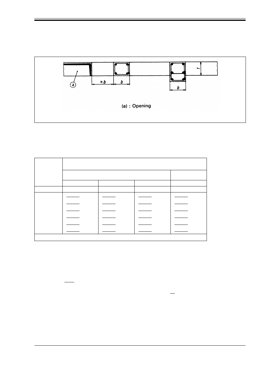
ENV 1992-1-2:1995
© BSI 03-2000
21
(6) Where the actual width or diameter b of column is at least 1,2 times the minimum value b
min
given
in Table 4.1 the axis distance a may be reduced to a value not less than the nominal cover required by
ENV 1992-1-1. Linear interpolation of the axis distance may be used for values b/b
min
between 1 and 1,2.
For such situation 4.2.3 (4) does not apply.
Table 4.1 — Minimum dimensions and axis distances for reinforced
concrete columns; rectangular and circular section
4.2.4 Walls
4.2.4.1
Non load-bearing walls (partitions)
(1) Where the fire resistance of a partition is only required to meet the thermal insulation criterion I and
integrity criterion E, the minimum wall thickness should not be less than that given in Table 4.2 below.
Requirements of axis distance may be disregarded.
(2) If calcareous or lightweight aggregates are used the minimum wall thickness given in Table 4.2 may
be reduced by|10 %|.
(3) To avoid excessive thermal deformation and subsequent failure of integrity between wall and slab, the
ratio of clear height of wall l
w
to wall thickness t should not exceed|40|.
NOTE t × b is the load bearing part of the cross section
Figure 4.3 — Exposure of built-in columns
Standard fire
resistance
Minimum dimensions (mm)
Column width
b
min
/axis distance
a
Column exposed on more than one side
Exposed on one
side
È
fi
= 0,2
È
fi
= 0,5
È
fi
= 0,7
È
fi
= 0,7
1
2
3
4
5
R 30
|150/10|
a
|150/10|
a
|150/10|
a
|100/10|
a
R 60
|150/10|
a
|180/10|
a
|200/10|
a
|120/10|
a
R 90
|180/10|
a
|210/10|
a
|240/35|
|140/10|
a
R 120
|200/40|
|250/40|
|280/40|
|160/45|
R 180
|240/50|
|320/50|
|360/50|
|200/60|
R 240
|300/50|
|400/50|
|450/50|
|300/60|
a
Normally the cover required by ENV 1992-1-1 will control.
Licensed copy:Heriot Watt University, 20/04/2004, Uncontrolled Copy, © BSI

ENV 1992-1-2:1995
22
© BSI 03-2000
Table 4.2 — Minimum wall thickness of non
load-bearing walls (partitions)
4.2.4.2
Load-bearing solid walls
(1) Adequate fire resistance of load-bearing reinforced concrete walls may be assumed if the data given
in Table 4.3 and the following rules are applied.
(2) For plain concrete walls (see ENV 1992-1-6) the minimum wall thickness values given in Table 4.3
may be used.
(3) 4.2.3 (2), (3) and (6) also apply for load-bearing solid walls.
Table 4.3 — Minimum dimensions and axis distances for load-bearing
reinforced concrete walls
4.2.5 Tensile members
(1) Fire resistance of reinforced or prestressed concrete tensile members may be assumed adequate if the
data given in Table 4.4 and the following rules are applied.
(2) Where excessive elongation of a tensile member affects the load bearing capacity of the structure it may
be necessary to reduce the steel temperature in the tensile member to 400 °C. In such situations the axis
distances in Table 4.4 should be increased by 10 mm. For the assessment of the reduced elongation
reference is made to appropriate documents.
(3) The cross-section of tensile members should not be less than 2b
min
2
, where b
min
is the minimum member
width given in Table 4.4.
Standard fire resistance
Minimum wall thickness (mm)
1
2
EI 30
|60|
EI 60
|80|
EI 90
|100|
EI 120
|120|
EI 180
|150|
EI 240
|175|
Standard fire
resistance
Minimum dimensions (mm)
Wall thickness/axis distance for
È
f
= 0,35
È
f
= 0,7
wall exposed on one
side
wall exposed on two
sides
wall exposed on one
side
wall exposed on two
sides
1
2
3
4
5
REI
30
|100/10|
a
|120/10|
a
|120/10|
a
|120/10|
a
REI
60
|110/10|
a
|120/10|
a
|130/10|
a
|140/10|
a
REI
90
|120/20|
a
|140/10|
a
|140/25|
|170/25|
REI 120
|150/25|
|160/25|
|160/35|
|220/35|
REI 180
|180/45|
|200/45|
|210/55|
|300/55|
REI 240
|230/60|
|250/60|
|270/70|
|360/70|
a
Normally the cover required by ENV 1992-1-1 will control.
Licensed copy:Heriot Watt University, 20/04/2004, Uncontrolled Copy, © BSI
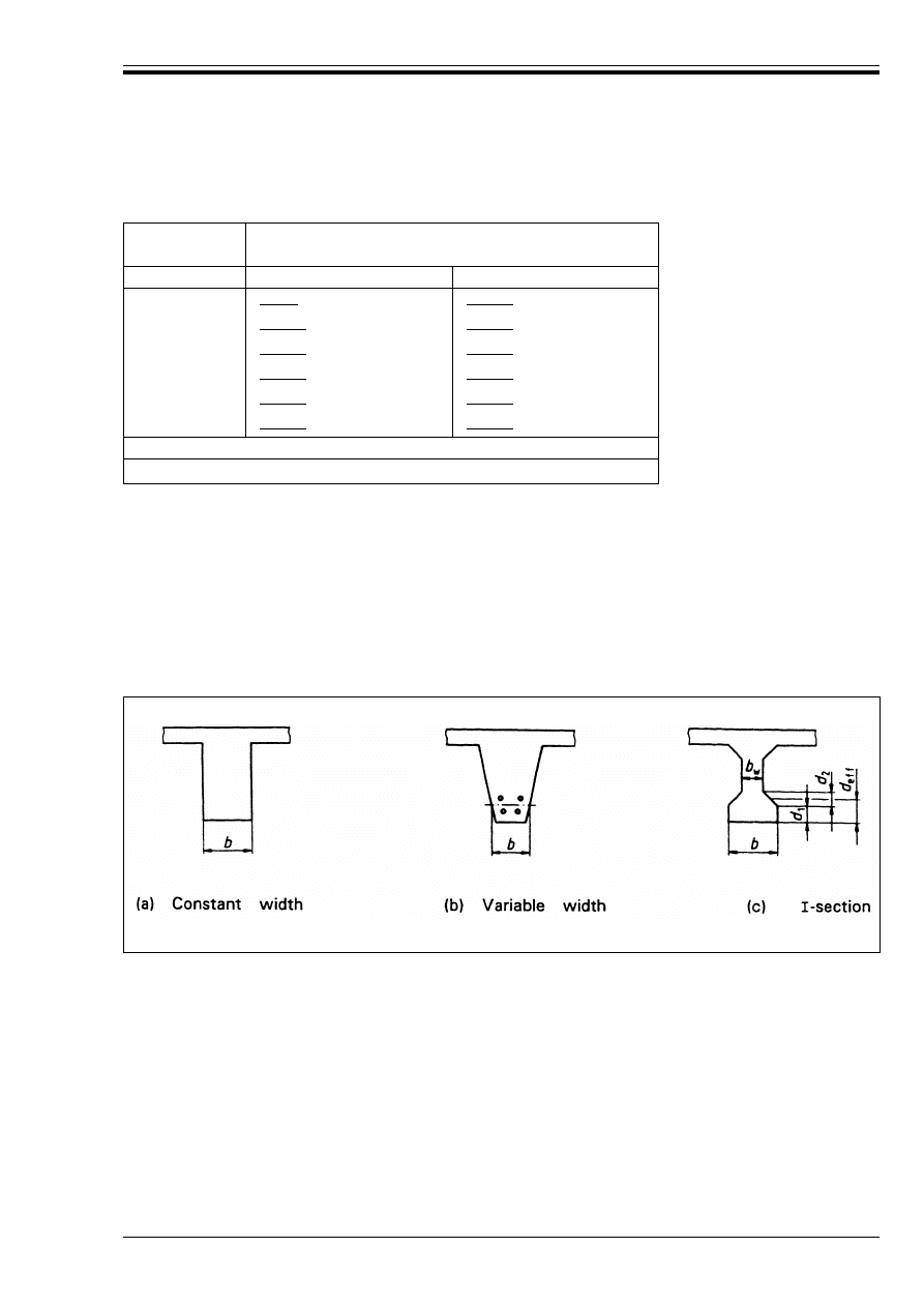
ENV 1992-1-2:1995
© BSI 03-2000
23
Table 4.4 — Minimum dimensions and axis distances for
reinforced and prestressed concrete tensile members
4.2.6 Beams
4.2.6.1
General
(1) Adequate fire resistance of reinforced and prestressed concrete beams may be assumed if the data
given in Table 4.5 to Table 4.7 together with the following rules are used.
(2) The Tables apply to beams which can be exposed to fire on three sides, i.e. the upper side is insulated
by slabs or other elements which continue their insulating function during the whole fire resistance period.
For beams, exposed to fire on all sides, 4.2.6.4 applies.
(3) Values in the Tables are valid for the cross-sections shown in Figure 4.4. Rules (5) to (8) ensure adequate
cross-sectional dimensions to protect the reinforcement.
(4) For beams with varying width [Figure 4.4 (b)] the minimum value b relates to the centroid of the tensile
reinforcement.
(5) The effective height d
eff
of the bottom flange of
I
-shaped beams with varying webs [Figure 4.4 (c)] should
not be less than:
where b
min
is the minimum value of beam width according to Table 4.5
This rule does not apply if an imaginary cross section [(a) in Figure 4.5] which fulfils the minimum
requirements with regard to fire resistance and which includes the whole reinforcement can be drawn
inside the actual cross section.
Standard fire
resistance
Minimum dimensions (mm)
Possible combinations of member width
b
min
/axis distance
a
1
2
3
R 30
|80/25|
|200/10|
a
R 60
|120/40|
|300/25|
R 90
|150/55|
|400/45|
R 120
|200/65|
|500/45|
R 180
|240/80|
|600/60|
R 240
|280/90|
|700/70|
For prestressed members the increase of axis distance according to 4.2.2(4) should be noted.
a
Normally the cover required by ENV 1992-1-1 will control.
Figure 4.4 — Definition of dimensions for different types of beam section
d
eff
= d
1
+ 0,5 d
2
W b
min
(4.8)
Licensed copy:Heriot Watt University, 20/04/2004, Uncontrolled Copy, © BSI
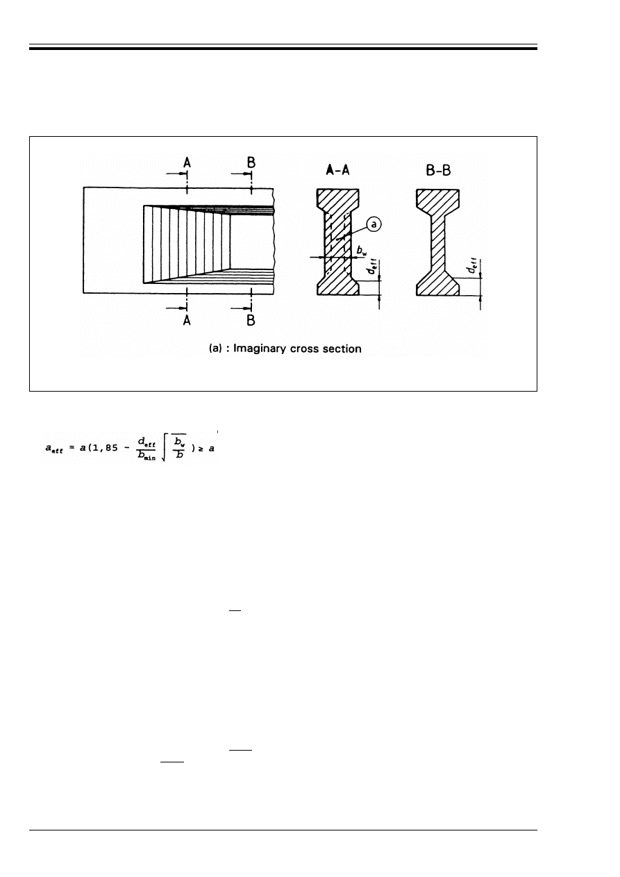
ENV 1992-1-2:1995
24
© BSI 03-2000
(6) Where the actual width of the bottom flange b exceeds the limit 1,4 b
w
, [b
w
denotes the actual width of
web, see Figure 4.4 (c)], the axis distance to the reinforcing or prestressing steel should be increased to:
where:
d
eff
is given by Equation (4.8)
b
min
is the minimum beam width given in Table 4.5.
(7) For flanges with b > 3,5 b
w
[see (6) above for definitions] 4.2.6.4 applies.
(8) Holes through the webs of beams do not affect the fire resistance provided that the remaining
cross-sectional area of the member in the tensile zone is not less than A
c
= 2b
2
min
where b
min
is given
by Table 4.5 below.
(9) Higher temperature concentrations occur at the bottom corners of beams. For this reason the axis
distance a
sd
to the side of beam for corner bar (tendon or wire) in the bottom of beams with only one layer
of reinforcement, should be increased by|10| mm for widths of beam up to that given in Column 4 of
Table 4.5 for simply supported beams, and Column 3 of Table 4.6 for continuous beams, for the relevant
standard fire resistance.
4.2.6.2
Simply supported beams
(1) Table 4.5 provides minimum values of axis distance to the soffit and sides of simply supported beams
together with minimum values of the width of beam, for standard fire resistances of R 30 to R 240.
4.2.6.3
Continuous beams
(1) Table 4.6 provides minimum values of axis distance to the soffit and sides of continuous beams together
with minimum values of the width of beam, for standard fire resistance of R 30 to R 240.
(2) Table 4.6 and the following rules apply for beams where the moment redistribution according to
ENV-1992-1-1, 2.5.3.4.2 does not exceed|15 %|. In the absence of a more rigorous calculation and where
the redistribution exceeds|15 %|, or the detailing rules of this Part 1-2 are not followed, each span of a
continuous beam should be assessed using Table 4.5 for simple supported beams.
Figure 4.5 —
I
-shaped beam with increasing web width b
w
satisfying the
requirements of an imaginary cross-section
(4.9)
Licensed copy:Heriot Watt University, 20/04/2004, Uncontrolled Copy, © BSI
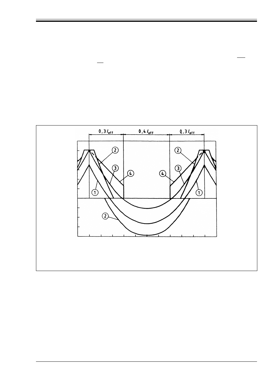
ENV 1992-1-2:1995
© BSI 03-2000
25
(3) The area of top reinforcement over each intermediate support for standard fire resistance of|R90|and
above, for up to a distance of|0,3|/
eff
(as defined in ENV 1992-1-1, 2.5.2.2.2) from the centre line of support
should not be less than (see Figure 4.6):
where:
x
is the distance from the section considered to the centre line of the support (x u 0,3/
eff
)
A
s,req
(0) is the area of top reinforcement required over the support, according to ENV 1992-1-1
A
s,req
(x) is the minimum area of top reinforcement required in the section considered but not less than
A
s
(x) required by ENV 1992-1-1.
Where l
eff
varies in the adjacent spans it should be taken as the greater value.
A
s,req
(x) = A
s,req
(0) × (1 – 2,5x/l
eff
)
(4.10)
Explanation:
(1) Diagram of bending moments for the actions in a fire situation at t = 0
(2) Envelope line of acting bending moments to be resisted by tensile reinforcement according to ENV 1992-1-1
(3) Diagram of bending moments in fire conditions
(4) Envelope line of resisting bending moments according to Equation (4.10)
Figure 4.6 — Envelope of resisting bending moments over supports in fire conditions
Licensed copy:Heriot Watt University, 20/04/2004, Uncontrolled Copy, © BSI
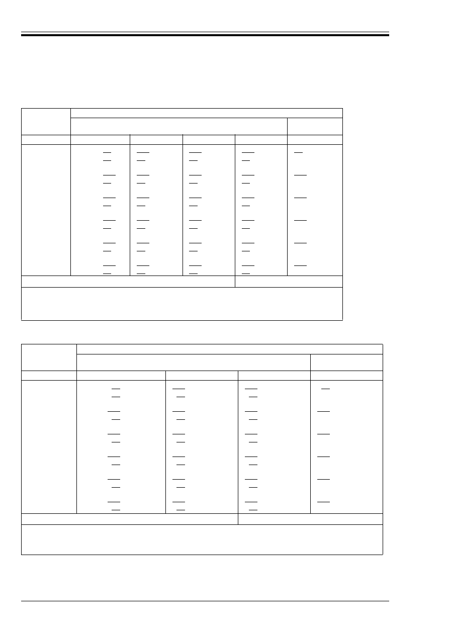
ENV 1992-1-2:1995
26
© BSI 03-2000
Table 4.5 — Minimum dimensions and axis distances for simply supported
beams made with reinforced and prestressed concrete
Table 4.6 — Minimum dimensions and axis distances for continuous beams
made with reinforced and prestressed concrete
(4) Table 4.6 applies to continuous beams using unbonded tendons only, where additional bonded top
reinforcement over intermediate supports is provided to ensure static equilibrium under fire conditions.
Standard fire
resistance
Minimum dimensions (mm)
Possible combinations of
a and b
min
where a is the average axis
distance and
b
min
is the width of beam
Web thickness
b
w
1
2
3
4
5
6
R 30
b
min
= |80|
|120|
|160|
|200|
|80|
a
=
|25|
|15|
a
|10|
a
|10|
a
R 60
b
min
= |120|
|160|
|200|
|300|
|100|
a
=
|40|
|35|
|30|
|25|
R 90
b
min
= |150|
|200|
|250|
|400|
|100|
a
=
|55|
|45|
|40|
|35|
R 120
b
min
= |200|
|240|
|300|
|500|
|120|
a
=
|65|
|55|
|50|
|45|
R 180
b
min
= |240|
|300|
|400|
|600|
|140|
a
=
|80|
|70|
|65|
|60|
R 240
b
min
= |280|
|350|
|500|
|500|
|160|
a
=
|90|
|80|
|75|
|70|
a
sd
= a + 10 mm
(see note below)
For prestressed beams the increase of axis distance according to 4.2.2(4) should be noted.
a
sd
is the axis distance to the side of beam for the corner bars (tendon or wire) of beams with only one layer of
reinforcement. For values of b
min
greater than that given in Column 4 no increase of a is required.
a
Normally the cover required by ENV 1992-1-1 will control.
Standard fire
resistance
Minimum dimensions (mm)
Possible combinations of
a and b
min
where a is the average axis distance
and
b
min
is the width of beam
Web thickness b
w
1
2
3
4
5
R 30
b
min
= |80|
|160|
|200|
|80|
a
=
|12|
a
|12|
a
|12|
a
R 60
b
min
= |120|
|200|
|300|
|100|
a
=
|25|
|12|
a
|12|
a
R 90
b
min
= |150|
|250|
|400|
|100|
a
=
|35|
|25|
|25|
R 120
b
min
= |220|
|300|
|500|
|120|
a
=
|45|
|35|
|35|
R 180
b
min
= |380|
|400|
|600|
|140|
a
=
|60|
|60|
|50|
R 240
b
min
= |480|
|500|
|700|
|160|
a
=
|70|
|70|
|60|
a
sd
= a + 10 mm (see note below)
For prestressed beams the increase of axis distance according to 4.2.2(4) should be noted.
a
sd
is the axis distance to the side of beam for the corner bars (tendon or wire) of beams with only one layer of reinforcement.
For values of b
min
greater than that given in Column 3 no increase of a is required.
a
Normally the cover required by ENV 1992-1-1 will control.
Licensed copy:Heriot Watt University, 20/04/2004, Uncontrolled Copy, © BSI
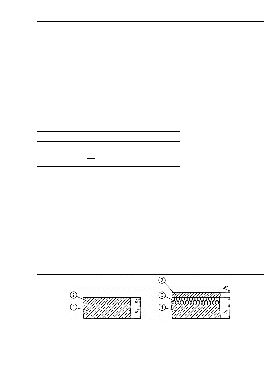
ENV 1992-1-2:1995
© BSI 03-2000
27
(5) The web thickness of
I
-shaped continuous beams b
w
[see Figure 4.4 (c)] should not be less than the
minimum value b
min
in Table 4.6, Columns 2 to 4, for a distance of 2h from an intermediate support unless
it can be shown that explosive spalling will not occur using Figure A.18.
(6) In order to prevent a concrete compression or shear failure of a continuous beam at the first
intermediate support, the beam width and web thickness should be increased for standard fire
resistances |R 120 – R 240|in accordance with Table 4.7, if both the following conditions exist:
a) no bending resistance is provided at the end support, either by the joint or beam (for the purposes
of this clause ENV 1992-1-1, 5.4.2.1.2 (1) does provide moment resistance when incorporated in a
joint which can transfer moment), and
b) V
sd
> 2/3 V
Rd2
at the first intermediate support, where V
Rd2
is the design shear resistance of the
compression struts according to ENV 1992-1-1, 4.3.2.
Table 4.7 — Reinforced and prestressed concrete
continuous
I
-beams; increased beam width and web
thickness for conditions according to 4.2.6.3 (6)
4.2.6.4
Beams exposed on all sides
(1) Table 4.5, Table 4.6 and Table 4.7 apply: however
— the height of the beam should not be less than the minimum width required for the respective fire
resistance period,
— the cross-sectional area of the beam should not be less than
Where b
min
is given by Table 4.5 to Table 4.7.
4.2.7 Slabs
4.2.7.1
General
(1) Fire resistance of reinforced and prestressed concrete slabs may be considered adequate if the values
in Table 4.8 and together with the following rules are applied.
(2) The minimum slab thickness h
s
given in Table 4.8 ensures adequate separating function (Criterion E
and I). Floor-finishes will contribute to the separating function in proportion to their thickness
(see Figure 4.7). If loadbearing function (Criterion R) is required only the necessary slab thickness assumed
for design to ENV 1992-1-1 may be taken.
(3) The rules given in 4.2.7.2 and 4.2.7.3 also apply for the flanges of T- or TT-shaped beams.
Standard fire
resistance
Minimum beam width
b
min
(mm) and web
thickness
b
w
(mm)
1
2
R 120
|220|
R 180
|380|
R 240
|480|
A
c
= 2b
2
min
(4.11)
Explanation:
(1) Concrete slab
(2) Flooring (non-combustible)
(3) Sound insulation (possibly combustible)
h
1
+ h
2
= h
s
as given in
Table 4.8
Figure 4.7 — Concrete slab with floor finishes
Licensed copy:Heriot Watt University, 20/04/2004, Uncontrolled Copy, © BSI
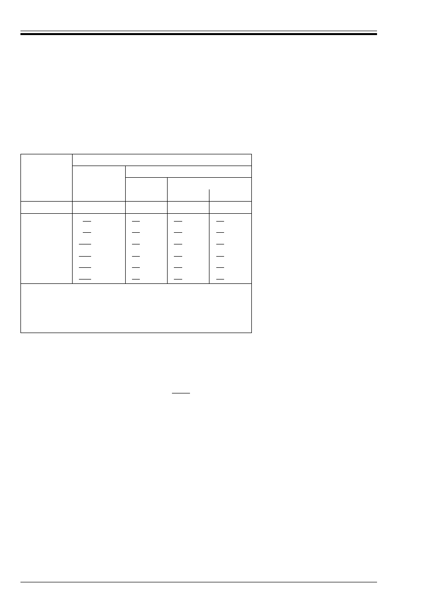
ENV 1992-1-2:1995
28
© BSI 03-2000
4.2.7.2
Simply supported slabs
(1) Table 4.8 provides minimum values of axis distance to the soffit of simply supported slabs for standard
fire resistances of R 30 to R 240.
(2) In two-way spanning slabs, a denotes the axis distance of the reinforcement in the lower layer.
Table 4.8 — Minimum dimensions and axis distances for
reinforced and prestressed concrete simply supported
one-way and two-way slabs
4.2.7.3
Continuous slabs
(1) The values given in Table 4.8 (Columns 2 and 4) also apply to one-way or two-way continuous slabs.
(2) The rules in 4.2.6.3 (2) and (3) for continuous beams also apply to continuous slabs. If these rules are
not followed each span of a continuous slab should be assessed as a simply supported slab using Table 4.8
(Columns 2, 3, 4 or 5 respectively).
(3) A minimum negative reinforcement A
s
W|0,005|A
c
over intermediate support should be provided if the
following conditions apply:
a) normal ductility steel is used (see ENV 1992-1-1, 3.2.4.2)
b) in two-span continuous slabs, no restraint to bending at end supports is provided by design provisions
according to ENV 1992-1-1 and/or by adequate detailing [see, for example, ENV 1992-1-1, 5.4.3.2.2 (2)].
c) no possibility is given to redistribute load-effects transverse to the span direction, such, for example,
intermediate walls or other supports in span direction, not taken into account in the design
(see Figure 4.8).
Standard fire
resistance
Minimum dimensions (mm)
slab thickness
h
s
(mm)
axis-distance
a
one way
two way:
l
y
/l
x
u 1,5
1,5 <
l
y
/l
x
u 2
1
2
3
4
5
REI 30
|60|
|10|
a
|10|
a
|10|
a
REI 60
|80|
|20|
|10|
a
|15|
a
REI 90
|100|
|30|
|15|
a
|20|
REI 120
|120|
|40|
|20|
|25|
REI 180
|150|
|55|
|30|
|40|
REI 240
|175|
|65|
|40|
|50|
l
x
and l
y
are the spans of a two-way slab (two directions at right angles) where l
y
is
the longer span.
For prestressed slabs the increase of axis distance according to 4.2.2(4) should be
noted.
The axis distance a in Column 4 and 5 for two way slabs relate to slabs supported
at all four edges. Otherwise, they should be treated as one-way spanning slab.
a
Normally the cover required by ENV 1992-1-1 will control.
Licensed copy:Heriot Watt University, 20/04/2004, Uncontrolled Copy, © BSI
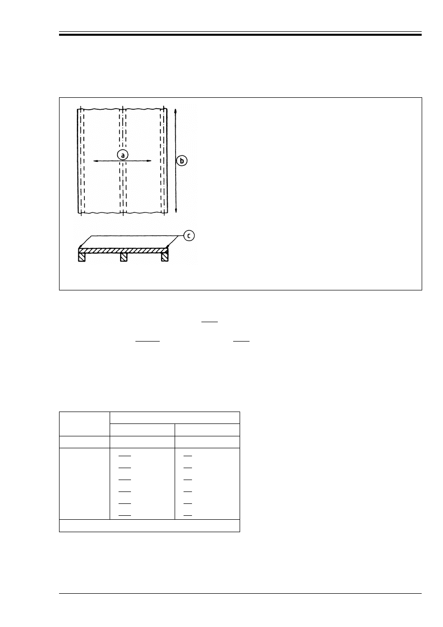
ENV 1992-1-2:1995
© BSI 03-2000
29
4.2.7.4
Flat slabs
(1) The following rules apply to flat slabs where the moment redistribution according to
ENV 1992-1-1, 2.5.3.5.4 does not exceed|15 %|. Otherwise axis distances should be taken as for
one-way slab (Column 3 in Table 4.8) and the minimum thickness from Table 4.9.
(2) For fire ratings of|REI 90|and above, at least|20 %|of the total top reinforcement in each direction
over intermediate supports, required by ENV 1992-1-1, should be continuous over the full span. This
reinforcement should be placed in the column strip.
(3) Minimum slab-thicknesses should not be reduced (e.g. by taking floor finishes into account).
(4) The axis distance a denotes the axis distance of the reinforcement in the lower layer.
Table 4.9 — Minimum dimensions and axis
distances for reinforced and prestressed
concrete flat slabs
4.2.7.5
Ribbed slabs
(1) For the assessment of the fire resistance of one-way reinforced and prestressed ribbed
slabs, 4.2.6.2, 4.2.6.3 and 4.2.7.3, Table 4.8, Columns 2 and 5, apply.
(2) For two-way reinforced and prestressed ribbed slabs, adequate fire resistance may be assumed if the
values in Table 4.10 and Table 4.11, together with the following rules, are applied.
Explanation:
(a) Span direction of slab
(b) Large extent of system without cross walls
(c) No rotational restraint provided
Figure 4.8 — Slab systems for which minimum reinforcement areas
according to 4.2.7.3 (3) should be provided
Standard fire
resistance
Minimum dimensions (mm)
slab-thickness
h
s
axis-distance
a
1
2
3
REI 30
|150|
|10|
a
REI 60
|200|
|15|
a
REI 90
|200|
|25|
REI 120
|200|
|35|
REI 180
|200|
|45|
REI 240
|200|
|50|
a
Normally the cover required by ENV 1992-1-1 will control.
Licensed copy:Heriot Watt University, 20/04/2004, Uncontrolled Copy, © BSI
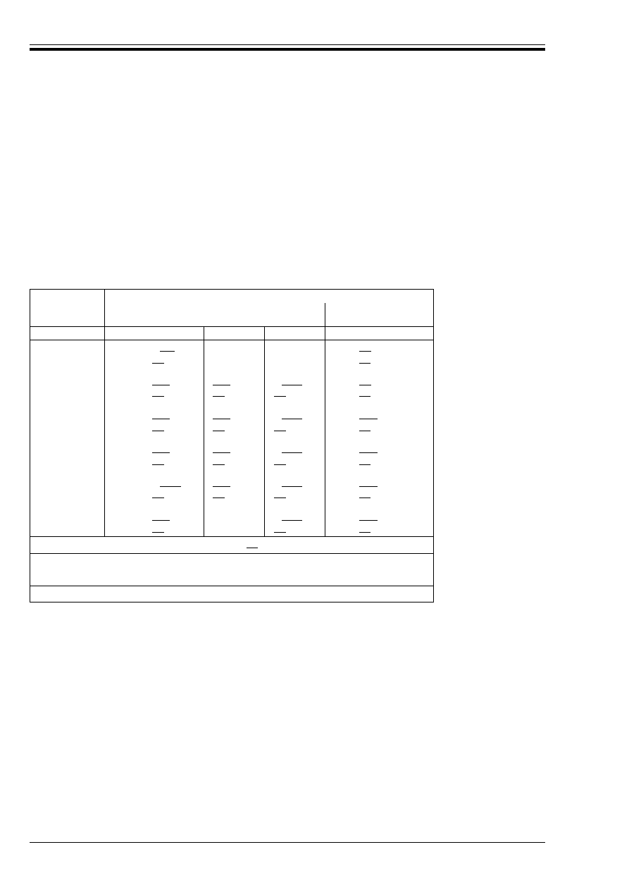
ENV 1992-1-2:1995
30
© BSI 03-2000
(3) The values in Table 4.10 and Table 4.11 are valid for ribbed slabs subjected to uniformly distributed
loading.
(4) For ribbed slabs with reinforcement placed in several layers, 4.2.6.1 (4) applies.
(5) In continuous ribbed slabs, the top reinforcement should be placed in the upper half of the flange.
(6) Table 4.10 is valid for simply supported, two-way spanning ribbed slabs. It is also valid for two-way
spanning ribbed slabs with at least one restrained edge and standard fire resistances lower than REI 180
where the detailing of the upper reinforcement does not meet the requirements in 4.2.6.3 (3).
Table 4.11 is valid for two-way spanning ribbed slabs with at least one restrained edge. For the detailing
of the upper reinforcement, 4.2.6.3 (3) applies for all standard fire resistances.
Table 4.10 — Minimum dimensions and axis distance for two-way
spanning, simply supported ribbed slabs in reinforced or prestressed
concrete
Standard Fire
Resistance
Minimum dimensions (mm)
Possible combinations of width of ribs
b
min
and
axis distance
a
slab thickness
h
s
and
axis distance
a in span
1
2
3
4
5
REI 30
b
min
= |W 80|
h
s
= |80|
a
=
|15|
a
a
= |10|
a
REI 60
b
min
= |100|
|120|
|W 200|
h
s
= |80|
a
=
|35|
|25|
|15|
a
a
= |10|
a
REI 90
b
min
= |120|
|160|
|W 250|
h
s
= |100|
a
=
|45|
|40|
|30|
a
= |15|
a
REI 120
b
min
= |160|
|190|
|W 300|
h
s
= |120|
a
=
|60|
|55|
|40|
a
= |20|
REI 180
b
min
= |W 220|
|260|
|W 410|
h
s
= |150|
a
=
|75|
|70|
|60|
a
= |30|
REI 240
b
min
= |280|
|W 500|
h
s
= |175|
a
=
|90|
|70|
a
= |40|
a
sd
= a +|10|
For prestressed ribbed slabs, the axis-distance a should be increased in accordance with 4.2.2(4).
a
sd
denotes the distance measured between the axis of the reinforcement lateral surface of the rib
exposed to fire.
a
Normally the cover required by ENV 1992-1-1 will control.
Licensed copy:Heriot Watt University, 20/04/2004, Uncontrolled Copy, © BSI
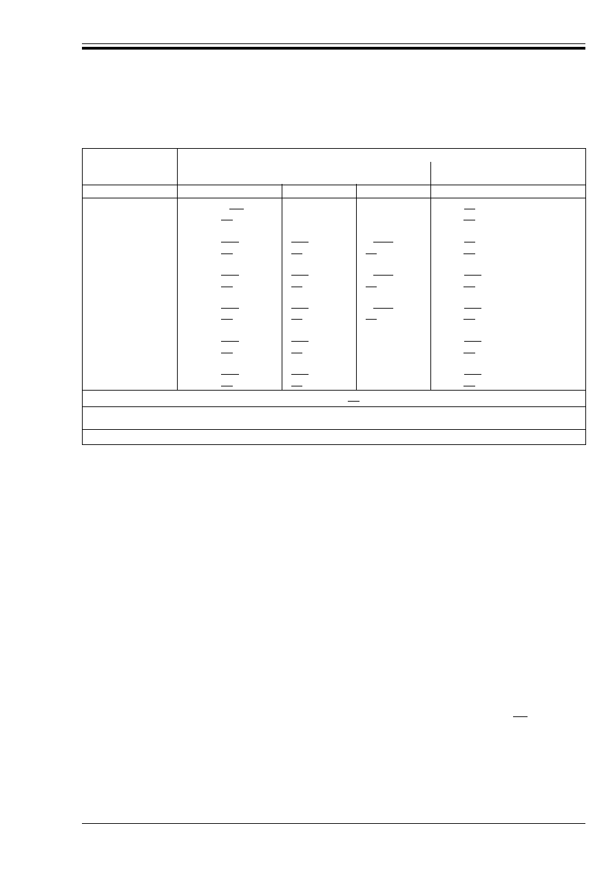
ENV 1992-1-2:1995
© BSI 03-2000
31
Table 4.11 — Minimum dimensions and axis distances for two-way spanning ribbed slabs in
reinforced or prestressed concrete with at least one restrained edge
4.3 Simplified calculation method
4.3.1 General
(1)P The simplified calculation method described below determines the ultimate load bearing capacity of a
heated cross section.
(2)P The method is applicable to structures subjected to a standard fire exposure until the time of
maximum gas-temperature.
(3)P The procedure is also applicable for the calculation of the ultimate resistance at a specified time for
any other fire exposure, if the temperature profiles corresponding to that exposure are known or calculated,
and correct data for material properties corresponding to it are used. However, this Part 1-2 only provides
temperature profiles and material data for the standard fire exposure up to the time of maximum gas
temperature.
(4) The procedure is to first determine the temperature profile of the cross section, reduce the concrete cross
section, the strength and the short term modulus of elasticity of concrete and reinforcement and then
calculate the ultimate load bearing capacity of the construction with the reduced cross section in
accordance with the rules of ENV 1992-1-1, and to compare the capacity with the relevant combination of
actions, see 2.4.2.
(5) Structural members should be detailed so that spalling, anchorage failure and lack of rotational
capacity will have a lower probability of occurrence than failure caused by bending moments, shear or axial
loads.
(6) The reduction factor µ given in ENV 1992-1-1, 4.2.1.3.3 (11) and (12) is assumed to be|1,0|in fire
design. Thus the design compressive strength of concrete in fire design is
Standard Fire
Resistance
Minimum dimensions (mm)
possible combinations of width of ribs
b
min
and axis
distance
a
slab thickness
h
s
and axis distance
a
in span
1
2
3
4
5
REI 30
b
min
= |W 80|
h
s
= |80|
a
=
|10|
a
a
= |10|
a
REI 60
b
min
= |100|
|120|
|W 200|
h
s
= |80|
a
=
|25|
|15|
a
|10|
a
a
= |10|
a
REI 90
b
min
= |120|
|160|
|W 250|
h
s
= |100|
a
=
|35|
|25|
|15|
a
a
= |15|
a
REI 120
b
min
= |160|
|190|
|W 300|
h
s
= |120|
a
=
|45|
|40|
|30|
a
= |20|
REI 180
b
min
= |310|
|600|
h
s
= |150|
a
=
|60|
|50|
a
= |30|
REI 240
b
min
= |450|
|700|
h
s
= |175|
a
=
|70|
|60|
a
= |40|
a
sd
= a +|10|
For prestressed ribbed slabs, the axis-distance a should be increased in accordance with 4.2.2(4).
a
sd
denotes the distance measured between the axis of the reinforcement lateral surface of the rib exposed to fire.
a
Normally the cover required by ENV 1992-1-1 will control.
f
cd
(G) = k
c
(G) f
ck
(20 °C).
(4.12)
Licensed copy:Heriot Watt University, 20/04/2004, Uncontrolled Copy, © BSI

ENV 1992-1-2:1995
32
© BSI 03-2000
4.3.2 Temperature profiles
(1) Temperatures in a concrete structure exposed to a fire may be determined from tests or by calculation.
The temperature profiles given in Annex B may be used where more accurate information is not available.
(2) The temperature profiles given in Annex B are acceptable for determining the temperatures in
cross-sections with silicious aggregate and exposed to a standard fire up to the time of maximum gas
temperature. The profiles are conservative for most other aggregates, but not in general for other than the
standard fire exposure.
4.3.3 Reduced cross section
(1) It is assumed that the isotherms in the compression zone of a rectangular cross section are parallel with
the sides.
(2) The fire damaged cross-section is represented by a reduced cross-section by ignoring a damaged zone of
thickness a
z
at the fire exposed surfaces, as shown in Figure 4.9.
(3) For a rectangular shape exposed to fire on one face only the width is assumed to be w, see Figure 4.9 c)
and the flange of Figure 4.9 f). Where two opposite faces are exposed to fire the width is assumed to be 2w
[see Figure 4.9 a), Figure 4.9 b), Figure 4.9 d), Figure 4.9 e) and the web of Figure 4.9 f)]. For any
rectangular part of a member an equivalent wall of thickness 2w is considered for which the thickness a
z
is calculated. For example the slab in Figure 4.9 c) is related to the equivalent wall in Figure 4.9 d), and
the flange of Figure 4.9 f) is also related to the equivalent wall in Figure 4.9 d), but the web of Figure 4.9 f)
is related to the equivalent wall of Figure 4.9 a).
(4) For the bottom and ends of rectangular members exposed to fire, where the width is less than the height,
the value of a
z
is assumed to be the same as that calculated for the sides [see Figure 4.9 b), Figure 4.9 e)
and Figure 4.9 f)].
(5) The compressive strength and the modulus of elasticity of the reduced concrete cross section are
assumed to be constant and equal to that calculated for the point M. M corresponds to any point in the
middle plane of the equivalent wall.
The thickness a
z
of the damaged zone and the reduced properties of the concrete should be determined
separately for each rectangular part of a cross section. This means that a
z
may be different for the flange
of a T shaped, cross section, from that of the web of the same cross section [see Figure 4.9 f)].
Licensed copy:Heriot Watt University, 20/04/2004, Uncontrolled Copy, © BSI
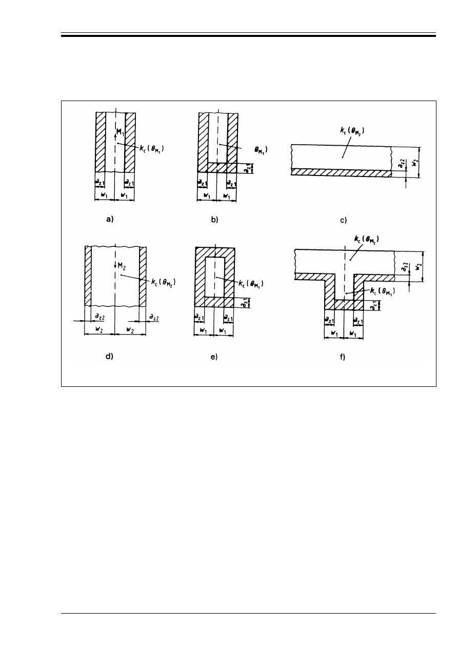
ENV 1992-1-2:1995
© BSI 03-2000
33
(6) The reduced compressive strength f
cd
(G
M
) at the point M in a member exposed to fire on both sides is
where G
M
is the temperature at the point M.
The reduced short term modulus of elasticity at this point is
The short term value of modulus of elasticity does not take account of the effect of creep or transient strain
(that part of the thermal expansion resisted by compressive stresses). Where second order effects for
columns and walls need to be considered the method given in ENV 1992-1-1 should be used with this value
of the modulus of elasticity and the reduced cross section of this clause. (The value of E
cd
(G
M
) cannot be
derived from Annex A where creep and transient strain are included in the data).
(7) The damaged zone a
z
is estimated for an equivalent wall exposed on both sides as follows:
a) The half thickness of the wall w is divided into n parallel zones of equal thickness, where n W 3
(see Figure 4.10).
b) The temperature is calculated for the middle of each zone.
c) The corresponding reductions k
c
(G
i
) of the compressive strength of the concrete are determined.
Figure 4.9 — Reductions of strength and cross-sections found by means of
equivalent walls (wall1 and wall2) exposed to fire on both sides
f
cd
(G
M
) = k
c
(G
M
) f
ck
(20 °C)
(4.13)
E
cd
(G
M
) = (k
c
(G
M
))
2
E
ck
(20 °C).
(4.14)
Licensed copy:Heriot Watt University, 20/04/2004, Uncontrolled Copy, © BSI

ENV 1992-1-2:1995
34
© BSI 03-2000
The reduced compressive strength and the damaged zone z may be estimated by means of Annex B for
a standard fire exposure until the time of maximum gas temperature or by means of the following
procedure.
d) The mean reduction coefficient incorporating a factor (1 – 0,2/n) which allows for the variation in
temperature within each zone, may be calculated using Equation (4.15):
e) The width of damaged zone for beams, slabs and members subjected to in-plane shear may be
calculated using Equation (4.16):
where k
c
(G
m
) denotes the reduction coefficient for concrete at point M.
For columns, walls and other constructions where second order effects may be calculated using
Equation (4.17):
(8) The reinforcement is taken into account with reduced strength and modulus of elasticity according to
the temperature of each bar, even if it is placed outside the reduced cross section, see Annex B.
(9) For compression bars a strain of 0,2 % with the corresponding stress reductions should be applied. For
bars in tension an increased stress as an effect of a larger strain may be taken into account. The reduction
of the modulus of elasticity of a bar may be assessed as equal to the reduction of the 0,2 % stress of the bar.
(10) Beams and slabs might become over-reinforced. For the analysis of this, the short term value of ¼
cu,max
may be assessed as
within the limits of the reduced cross section.
(11) In situations where a larger strain than 0,2 % is assumed for the reinforcement, it should be verified
that this larger strain occurs at the ultimate limit state under fire conditions.
Figure 4.10 — Divisions of a wall, exposed on both sides, into zones for use in calculation of
strength reduction and a
z
values
(4.15)
(4.16)
(4.17)
¼
cu,max
= 0,0035/k
c
(G
M
)
(4.18)
Licensed copy:Heriot Watt University, 20/04/2004, Uncontrolled Copy, © BSI

ENV 1992-1-2:1995
© BSI 03-2000
35
4.4 General calculation methods
4.4.1 General
(1)P General calculation methods may be used for individual members, for sub-assemblies or for entire
structures and for any type of cross-section.
(2)P General calculation methods shall provide a realistic analysis of structures exposed to fire. They shall
be based on fundamental physical behaviour leading to a reliable approximation of the expected behaviour
of the relevant structural component under fire conditions.
(3)P General calculation methods may include separate sub-models for the determination of:
a) the development and distribution of the temperature within structural members (thermal response
model);
b) the mechanical behaviour of the structure or of any part of it (mechanical response model).
(4)P Any potential failure mode not covered by the general calculation method shall be excluded by
appropriate detailing (e.g. insufficient rotational capacity, spalling, local buckling of compressed
reinforcement, shear and bond failure, damage to anchorage devices).
(5)P General calculation method may be used in association with any heating curve, provided that the
material properties are known for the relevant temperature range.
4.4.2 Thermal response
(1)P General calculation methods for thermal response shall be based on the acknowledged principles and
assumptions of the theory of heat transfer.
(2)P The thermal response model shall consider:
a) the thermal actions evaluated according to ENV 1991-2-2;
b) the temperature dependant thermal properties of the materials as specified in relevant documents
(see Annex A);
c) the contribution of protective layers, if any.
(3) The influence of moisture content and of migration of the moisture within concrete or protective layers
if any, may conservatively be neglected.
(4) The temperature profile in a reinforced concrete element may be assessed apart from the presence of
reinforcement.
(5) The effects of non-uniform thermal exposure and of heat transfer to adjacent building components may
be included where appropriate.
4.4.3 Mechanical response
(1)P General calculation methods for mechanical response shall be based on the acknowledged principles
and assumptions of the theory of structural mechanics, taking into account the changes of mechanical
properties with temperature.
(2)P The deformations at ultimate limit state implied by the calculation methods shall be limited as
necessary to ensure that compatibility is maintained between all parts of the structure.
(3)P Where relevant, the mechanical response of the model shall also take account of geometrical
non-linear effects.
(4)P The effects of thermally induced strains and stresses both due to temperature rise and due to
temperature differentials, shall be considered.
(5) The total strain º may be assumed to be:
where
º
th
is the thermal strain,
º
load
is the instantaneous stress-dependent strain
º
creep
is the creep strain and
º
tr
is the transient strain
º = º
th
+ º
load
+ º
creep
+ º
tr
(4.15)
Licensed copy:Heriot Watt University, 20/04/2004, Uncontrolled Copy, © BSI

ENV 1992-1-2:1995
36
© BSI 03-2000
During fire exposure the creep strain may be disregarded; its contribution may only be significant for
calculation of deflections after a fire.
(6) For practical calculations, deformations and indirect actions in hyperstatic structures during fire may
be assessed by means of imposed strains (mean axis elongation and curvature) estimated on the basis of
appropriate documents (see for example Annex D).
(7) The load bearing capacity of individual members, sub-assemblies or entire structures exposed to fire
may be assessed by plastic methods of analysis (ref. ENV 1992-1-1, 2.5.3).
(8) The plastic rotation capacity of reinforced concrete sections should be estimated in account of the
increased ultimate strains º
cu
and º
su
in hot condition. º
cu
will also be affected by the confinement
reinforcement provided.
(9) The compressed zone of a section, especially if directly exposed to fire (e.g. negative bending in
continuous beams), should be checked and detailed with particular regard to spalling or falling-off of
concrete cover.
(10) In the analysis of individual members or sub-assemblies the boundary conditions should be checked
and detailed in order to avoid failure due to the loss of adequate support to the members.
4.4.4 Validation of general calculation methods
(1)P The validity of the general calculation methods shall be verified by the following procedures:
a) justification of the design assumptions shall be made on basis of relevant test results.
b) sensitivity analysis of the effect of the critical parameters shall be performed.
4.5 Shear and torsion
(1) The shear and torsion capacity may be calculated according to the methods given in ENV 1992-1-1 using
reduced material properties and reduced prestress for each part of the section.
(2) When using the simplified calculation method of 4.3, ENV 1992-1-1 may be applied directly to the
reduced cross section.
(3) When using the simplified calculation method of 4.3, if no shear reinforcement is provided or the shear
capacity relies mainly on the reduced tensile strength of the concrete, the actual shear behaviour of the
concrete at elevated temperatures must be considered.
In the absence of more accurate information concerning the reduction of the tensile strength of concrete,
the values of k
ct
(G) given in Figure A.1 may be applied.
(4) When using the simplified calculation method of 4.3, for elements in which the shear capacity is
dependent on the tensile strength, special consideration should be given where tensile stresses are caused
by non-linear temperature distributions (e.g. voided slabs, thick beams, etc). A reduction in shear strength
should be taken equivalent to these tensile stresses.
4.6 Anchorage
(1) Where necessary for fire purposes the anchorage capacity may be calculated according to
ENV 1992-1-1 using reduced temperature related material properties [see 3.1 (4)].
Licensed copy:Heriot Watt University, 20/04/2004, Uncontrolled Copy, © BSI

ENV 1992-1-2:1995
© BSI 03-2000
37
5 Protective layers
(1)P Required fire resistance can be obtained by the application of protective layers.
(2) The properties and performance of the insulation material to be used for protective layers should be
assessed using appropriate test procedure.
(3) The test procedure should confirm that the material remains coherent and cohesive for all foreseen
temperatures and deformations. It should provide information concerning
— temperature at the relevant depths of the concrete cross-section related to the fire duration, protective
material and layer thickness, or
— where possible equivalent concrete thickness, related to the fire duration, or
— thermal material properties related to the temperature.
A further alternative is to provide a thermal analyses in accordance with the general calculation method
given in 4.4.
Licensed copy:Heriot Watt University, 20/04/2004, Uncontrolled Copy, © BSI
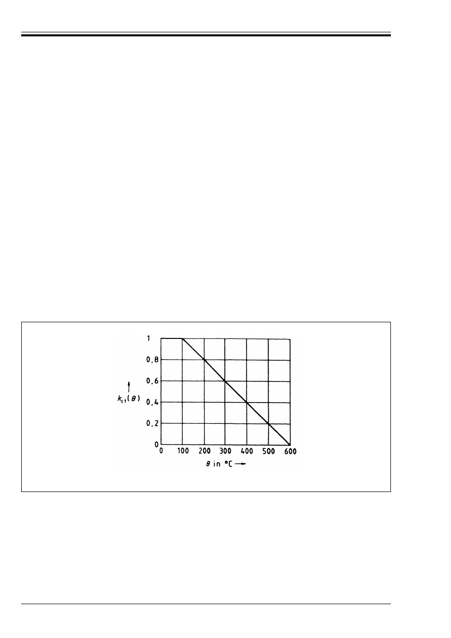
ENV 1992-1-2:1995
38
© BSI 03-2000
Annex A (informative)
Additional information on material properties
A.1 Strength and deformation properties of concrete
(1) The strength and deformation properties of uniaxial stressed concrete at elevated temperatures are
characterized by a set of stress-strain relationships with a shape as specified in Figure A.2.
(2) For a given concrete temperature, the stress-strain curves are defined by two parameters:
— the compressive strength f
c
(G)
— the strain º
c1
(G) corresponding to f
c
(G).
(3) Values for each of these parameters are given in Table A.1 as a function of the concrete temperatures.
For intermediate values of the temperature, linear interpolation is permitted.
(4) A graphical display of the two parameters of Table A.1 is given as a function of the concrete
temperatures in Figure A.3. Further illustration of the stress-strain relationships at various temperatures
is given in Figure A.4.
(5) The values given in Table A.1 are recommended values. Due to various ways of testing specimens, º
c1
(G)
shows considerable scatter, which is presented in Table A.2. Recommended values for º
cu
(G) defining the
range of the descending branch are also presented.
(6) The stress-s train relationships include in an approximate way the effect of high temperature creep.
(7) In case of natural fire simulation, particularly when considering the decreasing temperature branch,
the material model given here has to be modified.
(8) In all situations the ultimate tensile strength of concrete may be assumed to be zero, which is on the
safe side. If it is necessary to take account of the tensile strength, when using the simplified or general
method of calculation, Figure A.1 may be used.
Figure A.1 — Coefficient k
ct
(G) allowing for decrease of tensile strength, (f
ctk
) of
concrete at elevated temperature
Licensed copy:Heriot Watt University, 20/04/2004, Uncontrolled Copy, © BSI
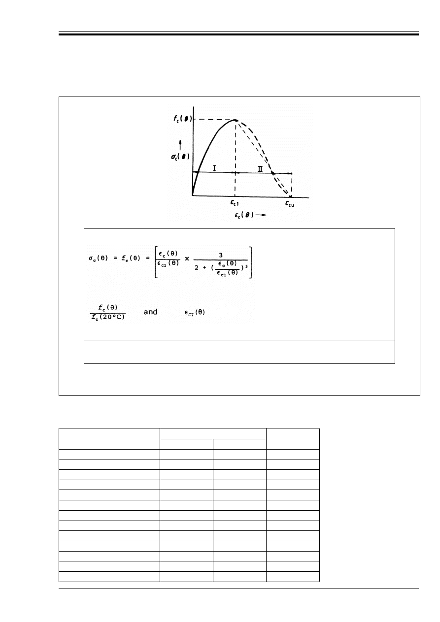
ENV 1992-1-2:1995
© BSI 03-2000
39
Table A.1 — Values for the main parameters of the stress-strain
relationships in compression of siliceous and calcareous concrete
at elevated temperatures (range I in
Figure A.2)
Range I
to be chosen according to the values of Table A.1
Range II: For numerical purposes a descending branch should be adopted.
Linear and non linear models are permitted.
Figure A.2 — Model for compression stress-strain relationships of siliceous and
calcareous concrete at elevated temperatures
Concrete Temperature
(°C)
f
c
(G)/f
c
(20 °C)
º
c1
(G) × 10
–3
siliceous
calcareous
20
1,00
1,00
2,5
100
0,95
0,97
3,5
200
0,90
0,94
4,5
300
0,85
0,91
6,0
400
0,75
0,85
7,5
500
0,60
0,74
9,5
600
0,45
0,60
12,5
700
0,30
0,43
14,0
800
0,15
0,27
14,5
900
0,08
0,15
15,0
1 000
0,04
0,06
15,0
1 100
0,01
0,02
15,0
1 200
0,00
0,00
—
Licensed copy:Heriot Watt University, 20/04/2004, Uncontrolled Copy, © BSI
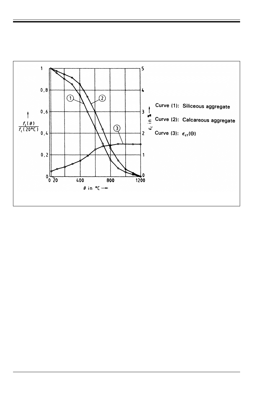
ENV 1992-1-2:1995
40
© BSI 03-2000
Figure A.3 — Parameters for stress-strain relationships of concrete at elevated
temperatures, according to
Figure A.2 and Table A.1
Licensed copy:Heriot Watt University, 20/04/2004, Uncontrolled Copy, © BSI
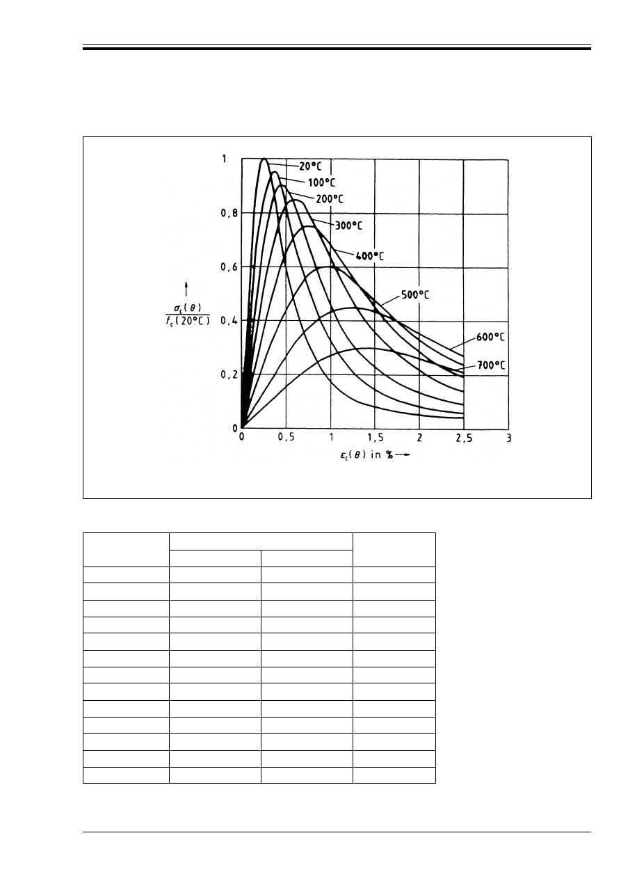
ENV 1992-1-2:1995
© BSI 03-2000
41
Table A.2 — Recommended values for º
c1
(G) and º
cu
(G) and
admissible range of º
c1
(G)
Figure A.4 — Stress-strain relationships of siliceous concrete under uniaxial
compression at elevated temperatures
Concrete
Temperature
(°C)
º
c1
(G) × 10
–3
º
cu
(G) × 10
–3
Recommended
Range
Recommended
20
2,5
2,5
20,0
100
2,5 – 4,0
3,5
22,5
200
3,0 – 5,5
4,5
25,0
300
4,0 – 7,0
6,0
27,5
400
4,5 – 10,0
7,5
30,0
500
5,5 – 15
9,5
32,5
600
6,5 – 25
12,5
35,0
700
7,5 – 25
14,0
37,5
800
8,5 – 25
14,5
40,0
900
10 – 25
15,0
42,5
1 000
10 – 25
15,0
45,0
1 100
10 – 25
15,0
47,5
1 200
—
—
—
Licensed copy:Heriot Watt University, 20/04/2004, Uncontrolled Copy, © BSI
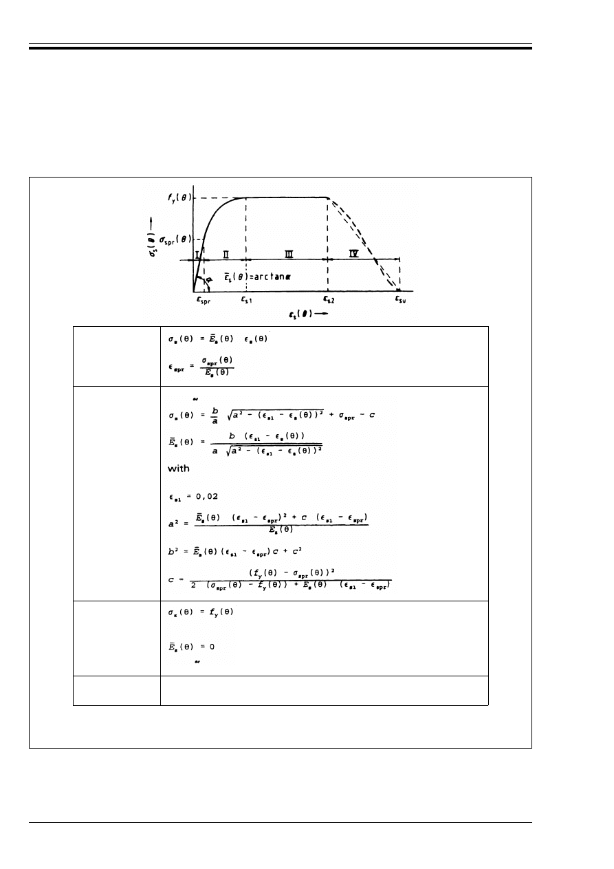
ENV 1992-1-2:1995
42
© BSI 03-2000
A.2 Strength and deformation properties of steel
(1) The strength and deformation properties of steel at elevated temperatures are characterized by a set of
stress-strain relationships with a linear elliptical shape as specified in Figure A.5.
Range I elastic
Range II
non-linear
Range III plastic
Range IV
For numerical purposes a descending branch should be adopted.
Linear and non-linear models are permitted.
Figure A.5 — Model for stress-strain relationships of reinforcing and prestressing steels
at elevated temperatures (notations for prestressing steels “p” instead of “s”)
Licensed copy:Heriot Watt University, 20/04/2004, Uncontrolled Copy, © BSI
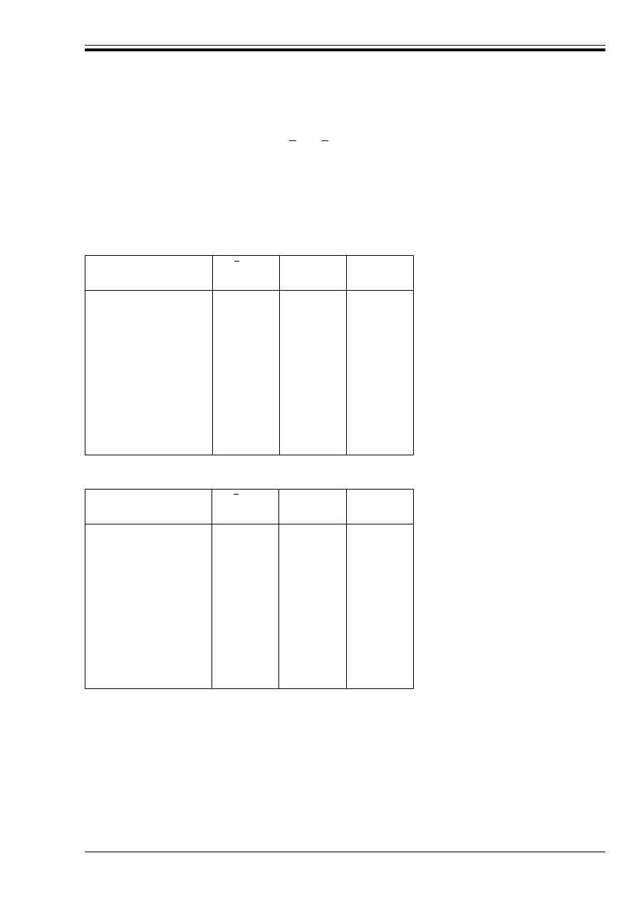
ENV 1992-1-2:1995
© BSI 03-2000
43
(2) For a given steel temperature, the stress-strain curves of Figure A.5 are defined by three parameters:
— the slope of the linear elastic range
for reinforcement and prestressing steels
respectively,
— the proportional limit Ö
spr
(G), Ö
ppr
(G) respectively and
— the maximum stress level f
y
(G), f
py
(G) respectively.
Values for each of the above parameters are given as a function of the steel temperature for various types
of reinforcing and prestressing steels in Table A.3 – Table A.6.
Table A.3 — Values for the parameters of the
stress-strain relationship of hot rolled reinforcing steel
Table A.4 — Values for the parameters of the stress-strain
relationship of cold worked reinforcing steel
Steel Temperature
(°C)
20
100
200
300
400
500
600
700
800
900
1 000
1 100
1 200
1,00
1,00
0,87
0,72
0,56
0,40
0,24
0,08
0,06
0,05
0,03
0,02
0,00
1,00
0,96
0,92
0,81
0,63
0,44
0,26
0,08
0,06
0,05
0,03
0,02
0,00
1,00
1,00
1,00
1,00
0,94
0,67
0,40
0,12
0,11
0,08
0,05
0,03
0,00
Steel Temperature
(°C)
20
100
200
300
400
500
600
700
800
900
1 000
1 100
1 200
1,00
1,00
0,90
0,80
0,70
0,60
0,31
0,13
0,09
0,07
0,04
0,02
0,00
1,00
1,00
0,81
0,61
0,42
0,36
0,18
0,07
0,05
0,04
0,02
0,01
0,00
1,00
1,00
1,00
1,00
1,00
0,78
0,47
0,23
0,11
0,06
0,04
0,02
0,00
E
s
G
( )
,
E
p
G
( )
E
s
G
( )
E
s
20
°
C
(
)
-----------------------
Ö
spr
G
( )
f
0,2
20
°
C
(
)
-------------------------
f
y
G
( )
f
0,2
20
°
C
(
)
-------------------------
E
s
G
( )
E
s
20
°
C
(
)
-----------------------
Ö
spr
G
( )
f
0,2
20
°
C
(
)
-------------------------
f
y
G
( )
f
0,2
20
°
C
(
)
-------------------------
Licensed copy:Heriot Watt University, 20/04/2004, Uncontrolled Copy, © BSI

ENV 1992-1-2:1995
44
© BSI 03-2000
Table A.5 — Values for the parameters of the stress-strain
relationship of quenched and tempered prestressing steel
Table A.6 — Values for the parameters of the stress-strain
relationship of cold worked prestressing steel
(3) A graphical display of the parameters of Table A.3 – Table A.6 is given in Figure A.7, Figure A.9,
Figure A.11 and Figure A.13. Further illustration of the stress-strain relationships at various
temperatures is given in Figure A.6, Figure A.8, Figure A.10 and Figure A.12.
Steel Temperature
(°C)
20
100
200
300
400
500
600
700
800
900
1 000
1 100
1 200
1,00
0,76
0,61
0,52
0,41
0,20
0,15
0,10
0,06
0,03
0,00
0.00
0,00
1,00
0,77
0,62
0,58
0,52
0,14
0,11
0,09
0,06
0,03
0,00
0,00
0,00
1,00
0,98
0,92
0,86
0,69
0,26
0,21
0,15
0,09
0,04
0,00
0,00
0,00
Steel Temperature
(°C)
20
100
200
300
400
500
600
700
800
900
1 000
1 100
1 200
1,00
0,98
0,95
0,88
0,81
0,54
0,41
0,10
0,07
0,03
0,00
0,00
0,00
1,00
0,68
0,51
0,32
0,13
0,07
0,05
0,03
0,02
0,01
0,00
0,00
0,00
1,00
0,99
0,87
0,72
0,46
0,22
0,10
0,08
0,05
0,03
0,00
0,00
0,00
E
p
G
( )
E
p
20
°
C
(
)
------------------------
Ö
ppr
G
( )
f
p0,2
20
°
C
(
)
---------------------------
f
py
G
( )
f
p0,2
20
°
C
(
)
---------------------------
E
p
G
( )
E
p
20
°
C
(
)
------------------------
Ö
ppr
G
( )
f
p0,2
20
°
C
(
)
---------------------------
f
py
G
( )
f
p0,2
20
°
C
(
)
---------------------------
Licensed copy:Heriot Watt University, 20/04/2004, Uncontrolled Copy, © BSI
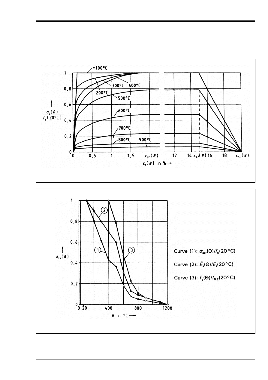
ENV 1992-1-2:1995
© BSI 03-2000
45
Figure A.6 — Stress-strain relationships of hot-rolled reinforcing steels at elevated
temperatures, according to
Figure A.5 and Table A.3
Figure A.7 — Parameters for stress-strain relationships of hot-rolled reinforcing steels at
elevated temperatures, according to
Figure A.5 and Table A.3
Licensed copy:Heriot Watt University, 20/04/2004, Uncontrolled Copy, © BSI
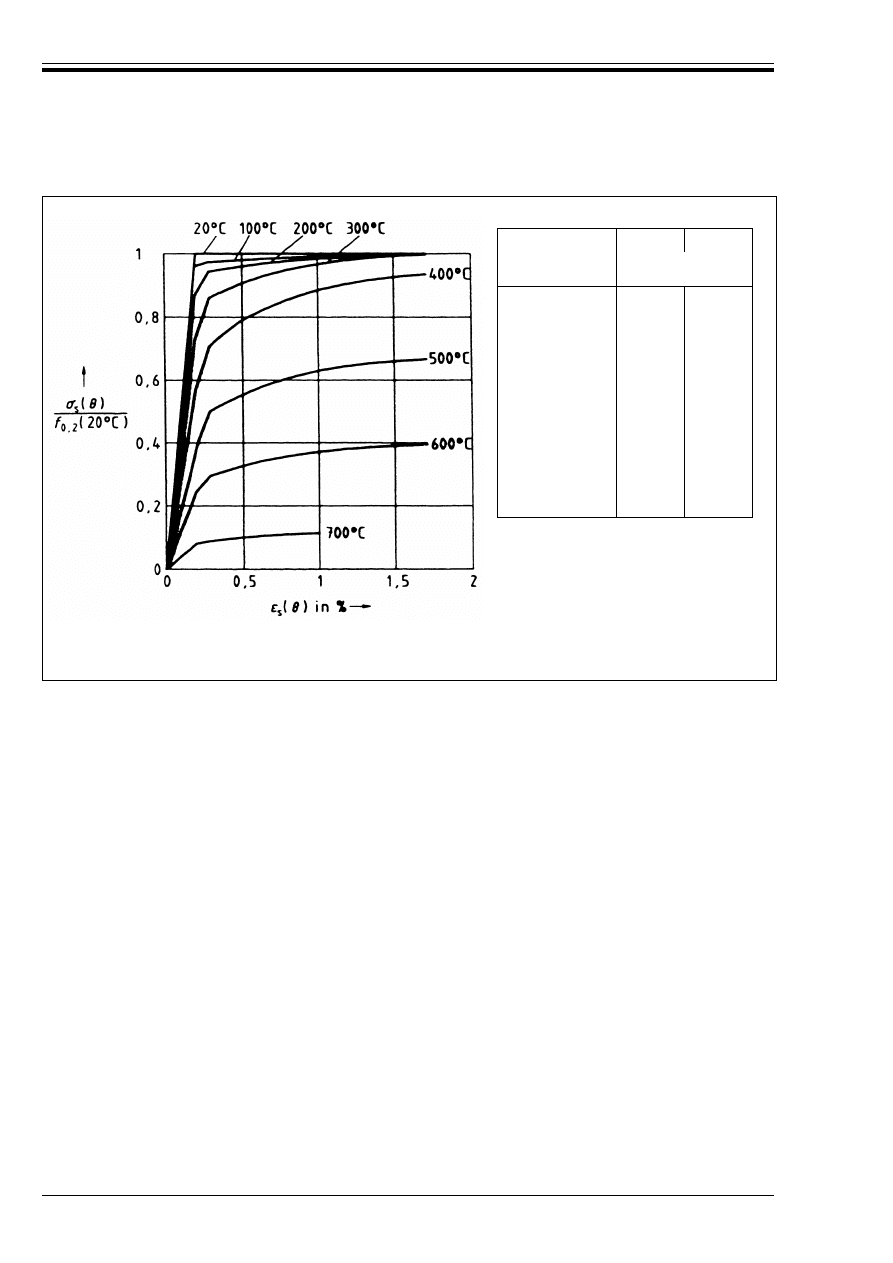
ENV 1992-1-2:1995
46
© BSI 03-2000
Steel
Temperature
(°C)
º
p2
(G)
º
pu
(G)
Recommended
values
(%)
20
100
200
300
400
500
600
700
800
900
1 000
1 100
1 200
5
5
5
5,5
6
6,5
7
7,5
8
8,5
9
9,5
10
10
10
10
10,5
11
11,5
12
12,5
13
13,5
14
14,5
15
Figure A.8 — Stress-strain relationships for cold-worked reinforcing steels at elevated
temperatures, according to
Figure A.5 and Table A.4
Licensed copy:Heriot Watt University, 20/04/2004, Uncontrolled Copy, © BSI
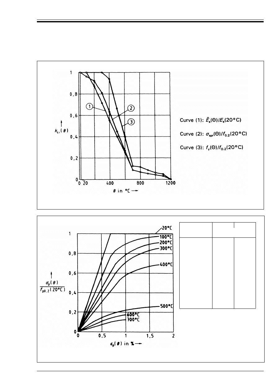
ENV 1992-1-2:1995
© BSI 03-2000
47
Figure A.9 — Parameters for stress-strain relationships of cold-worked reinforcing
steels at elevated temperatures, according to
Figure A.5 and Table A.4
Steel
Temperature
(°C)
º
p2
(G)
º
pu
(G)
Recommended
values
(%)
20
100
200
300
400
500
600
700
800
900
1 000
1 100
1 200
5
5
5
5
6
6,5
7
7,5
8
8,5
9
9,5
10
10
10
10
10,5
11
11,5
12
12,5
13
13,5
14
14,5
15
Figure A.10 — Stress-strain relationships for quenched and tempered
prestressing steels (bars) at elevated temperatures, according to
Figure A.5 and Table A.5
Licensed copy:Heriot Watt University, 20/04/2004, Uncontrolled Copy, © BSI
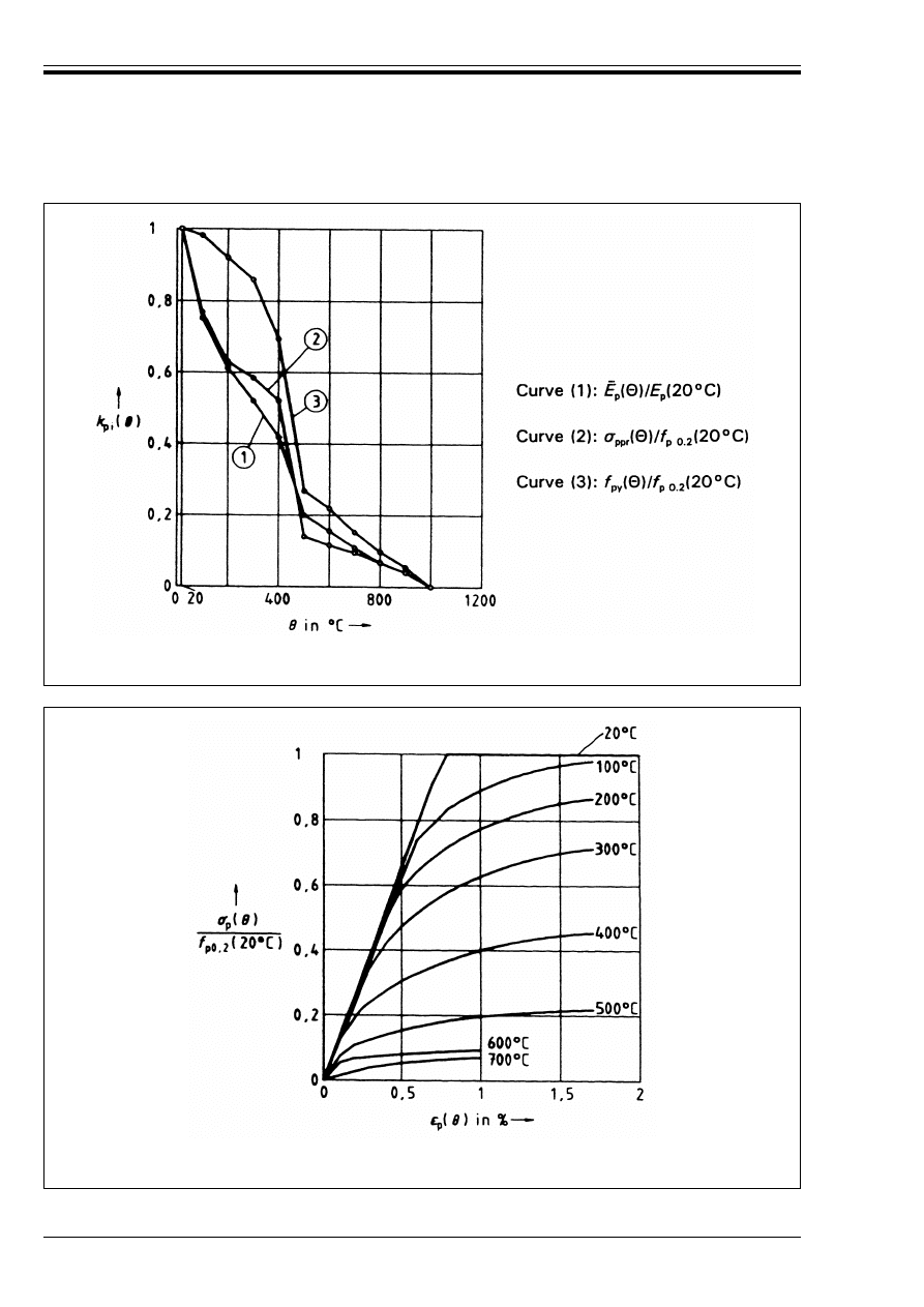
ENV 1992-1-2:1995
48
© BSI 03-2000
Figure A.11 — Parameters for stress-strain relationships of quenched and tempered
prestressing steels (bars) at elevated temperatures, according to
Figure A.5 and Table A.5
Figure A.12 — Stress-strain relationships for cold-worked prestressing steels (wires
and strands) at elevated temperatures, according to
Figure A.5 and Table A.6
Licensed copy:Heriot Watt University, 20/04/2004, Uncontrolled Copy, © BSI
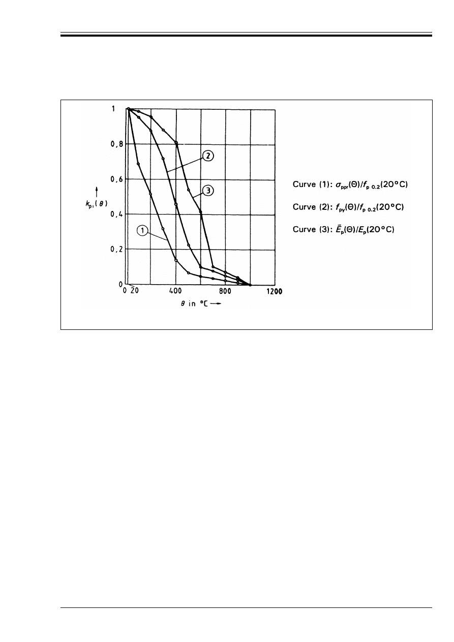
ENV 1992-1-2:1995
© BSI 03-2000
49
(4) The stress-strain relationships include in an approximate way the effect of high temperature creep.
As creep effects are not explicitly considered, this material model has only been checked for heating rates
similar to those appearing under standard fire conditions. For heating rates outside the above range, the
reliability of the strength and deformation properties used for steel must be demonstrated explicitly.
(5) In case of natural fire simulation, particularly when considering the decreasing temperature branch,
the stress-strain relationships given here may be used as a sufficiently precise approximation in case of
hot-rolled steels. At the present time, verified formulations of properties for the decreasing branch are not
available for other types of steel.
(6) The stress-strain relationships may be applied for steel in tension as well as in compression.
A.3 Thermal properties
A.3.1
Concrete (siliceous, calcareous and lightweight aggregates)
(1) The thermal elongation %l/l of concrete may be adopted according to Equations (A.1) – (A.5).
Figure A.13 — Parameters for stress-strain relationships of cold-worked prestressing steels
(wires and strands) at elevated temperatures, according to
Figure A.5 and Table A.6
siliceous aggregates:
for 20 °C < G u 700 °C
(%l/l)
c
= (– 1,8 × 10
–4
) + (9 × 10
– 6
G) + (2,3 × 10
–11
G
3
)
(A.1)
for 700 °C < G u 1 200 °C
(%l/l)
c
= 14 × 10
–3
(A.2)
calcareous aggregates:
for 20 °C < G u 805 °C
(%l/l)
c
= (– 1,2 × 10
–4
) + (6 × 10
–6
G) + (1,4 × 10
–11
G
3
)
(A.3)
for 805 °C < G u 1 200°
(%l/l)
c
= 12 × 10
–3
(A.4)
lightweight aggregates:
for 20 °C < G u 1200 °C
(%l/l)
c
= 8 × 10
– 3
(G – 20)
(A.5)
Licensed copy:Heriot Watt University, 20/04/2004, Uncontrolled Copy, © BSI
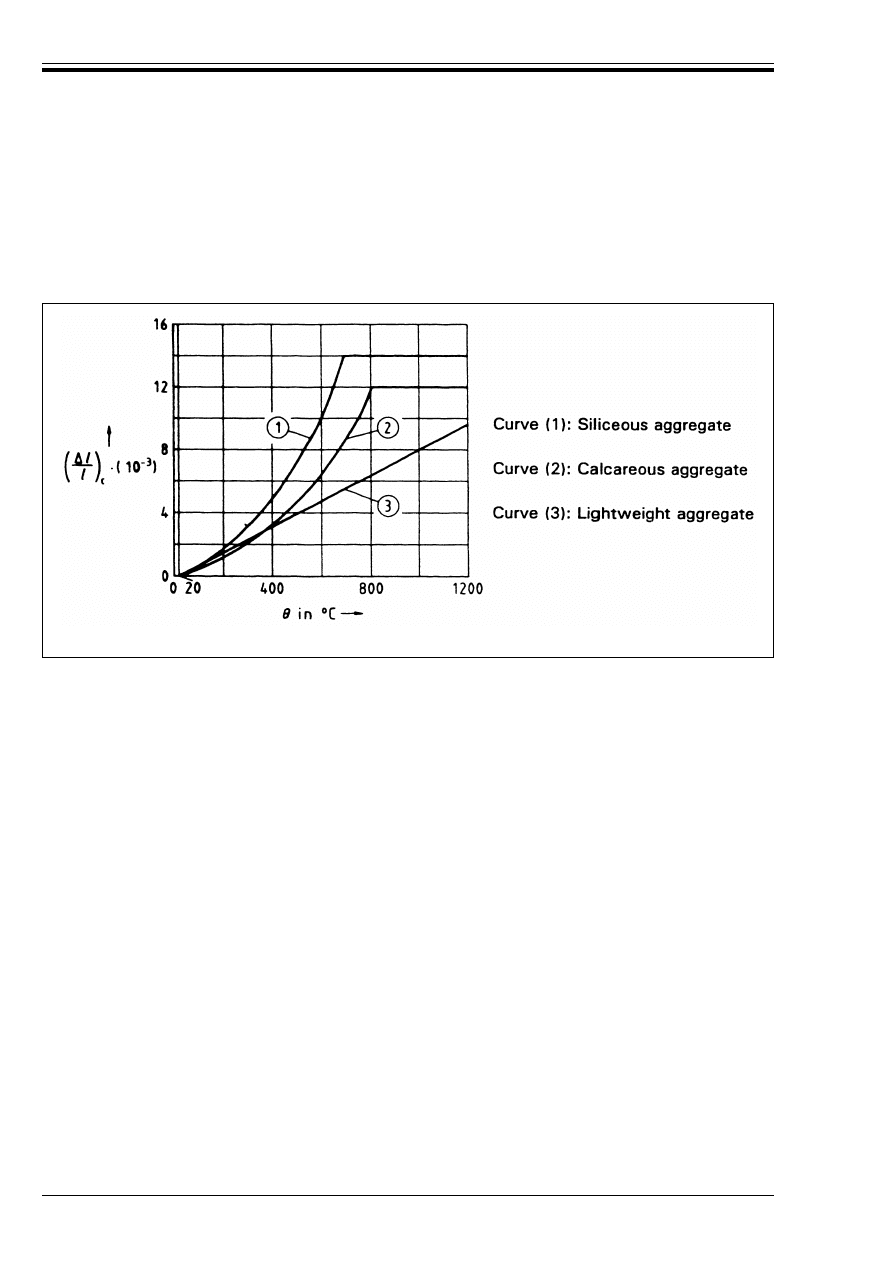
ENV 1992-1-2:1995
50
© BSI 03-2000
where:
l
c
is the length at room temperature
%l
c
is the temperature induced elongation
G is the concrete temperature (°C)
The above equations are presented graphically in Figure A.14 below.
If only an approximate answer is required (simple calculation, estimation) the coefficient of thermal
elongation may be used and considered as independent of the concrete temperature:
(%l/l)
c
= 18 × 10
–3
G for concrete with siliceous aggregates
(%l/l)
c
= 12 × 10
–3
G for concrete with calcareous aggregates
(%l/l)
c
= 8 × 10
–3
G for concrete with lightweight aggregates.
(2) The specific heat c
c
of concrete may be adopted according to Equations (A.6) and (A.7)
(see Figure A.15):
In case the moisture content is not considered on the level of the heat and mass balance, the function given
for the specific heat of concrete with siliceous or calcareous aggregates may be completed by a peak value
situated between 100 °C and 200 °C such as
c
c,peak
= 1 875 J/kgK for a humidity of 2 % of concrete weight
c
c,peak
= 2 750 J/kgK for a humidity of 4 % of concrete weight.
If only an approximate answer is required (simple calculation, estimation), the specific heat may be
considered as independent of the concrete temperature c
c
= 1 000 J/kgK for concrete with siliceous or
calcareous aggregates.
Figure A.14 — Thermal elongation of concrete
Concrete with siliceous or calcareous aggregates:
for 20 °C < G u 1 200 °C
c
c
= 900 + 80 G/120 – 4(G/120)
2
(J/kgK)
(A.6)
Concrete with lightweight aggregates:
for 20 °C < G u 1 200 °C
c
c
= 840 (J/kgK)
(A.7)
Licensed copy:Heriot Watt University, 20/04/2004, Uncontrolled Copy, © BSI
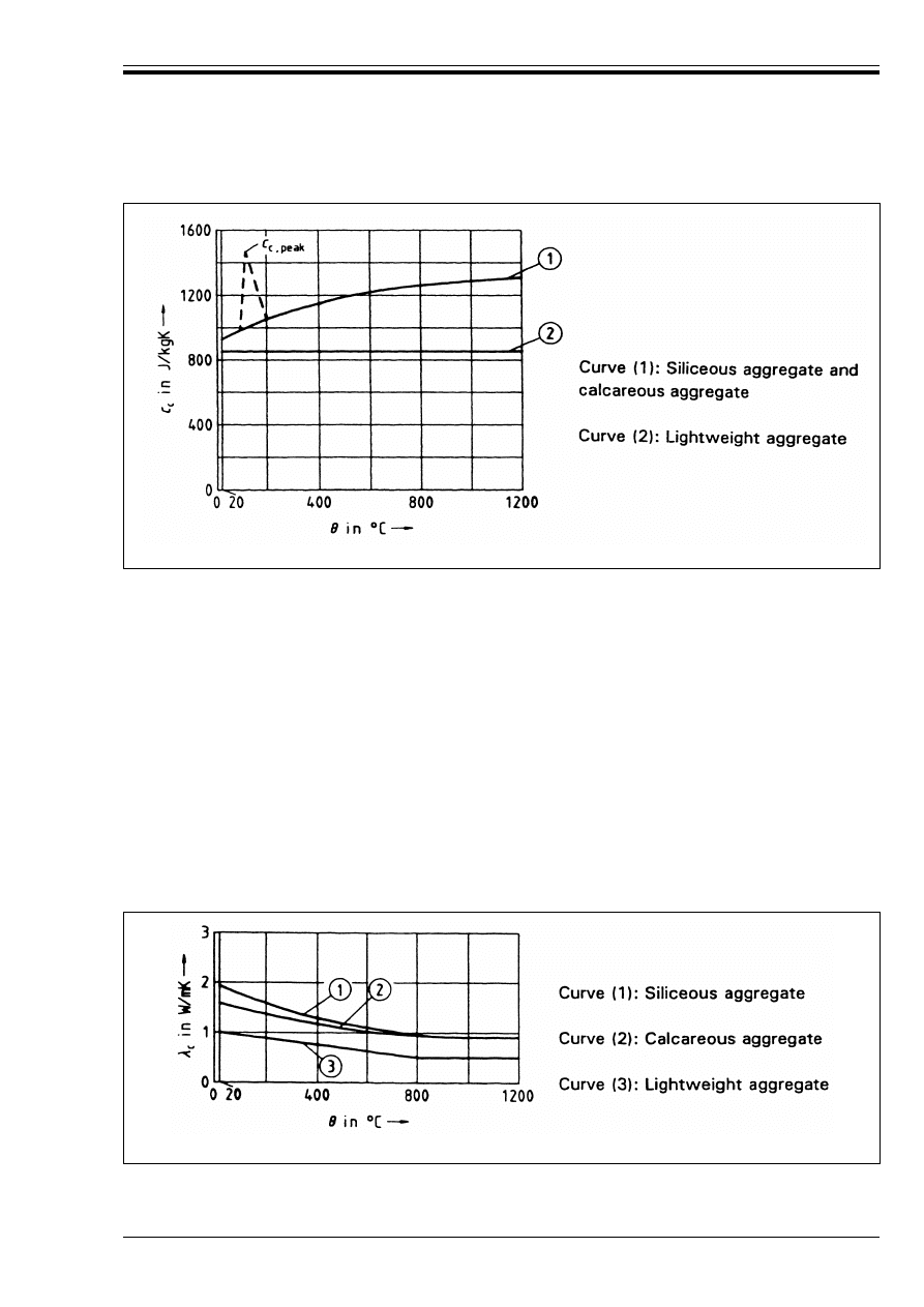
ENV 1992-1-2:1995
© BSI 03-2000
51
(3) The thermal conductivity Æ
c
of concrete may be calculated according to Equations (A.8) to (A.11):
The above Equations are presented graphically in Figure A.16.
Figure A.15 — Specific heat of concrete
Concrete with siliceous aggregates:
for 20 °C < G u 1 200 °C
Æ
c
= 2 – 0,24 G/120 + 0,012(G/120)
2
(W/Mk)
(A.8)
Concrete with calcareous aggregates:
for 20 °C < G
c
u 1 200 °C
2
c
= 1,6 – 0,16 G/120 + 0,008(G/120)
2
(W/Mk)
(A.9)
Concrete with lightweight aggregates:
for 20 °C < G u 800 °C
2
c
= 1,0 – G/1 600 (W/Mk)
(A.10)
for 800 °C < G u 1 200°
2
c
= 0,5 (W/Mk)
(A.11)
Figure A.16 — Thermal conductivity of concrete
Licensed copy:Heriot Watt University, 20/04/2004, Uncontrolled Copy, © BSI

ENV 1992-1-2:1995
52
© BSI 03-2000
If only an approximate answer is required (simple calculation, estimation), the thermal conductivity may
be considered as independent of the concrete temperature:
Æ
c
= 1,60 W/Mk for concrete with siliceous aggregates
Æ
c
= 1,30 W/Mk for concrete with calcareous aggregates
Æ
c
= 0,80 W/Mk for concrete with lightweight aggregates
(4) The density Ô
c
of unreinforced concrete may be considered as independent of the concrete temperature
and may be evaluated according to ENV 1992-1-2.
For thermal response models the value Ô
c
= 2 300 kg/m
3
may be adopted for normal dense concrete
(siliceous or calcareous).
The density may also be reduced by 100 kg/m
3
after having reached 100 °C, due to the evaporation of free
water.
(5) The moisture content of concrete may be taken equal to the equilibrium moisture content. If these data
are not available, moisture content may be considered u 2 % of the concrete weight.
A high moisture content delays the heating up of concrete, but increases the risk of spalling.
(6) If only an approximate answer is required (simple calculation, estimation), the thermal diffusivity of
concrete a
c
(m
2
/s) may be used.
It may be considered as independent of the concrete temperature:
a
c
= 0,69 × 10
– 6
m
2
/s for concrete with siliceous aggregates
a
c
= 0,56 × 10
– 6
m
2
/s for concrete with calcareous aggregates
dependent on the density for lightweight concrete.
A.3.2
Steel (reinforcing and prestressing)
(1) The thermal elongation %l/l of steel may be adopted according to Equations (A.11) – (A.15).
where:
l
s
, l
p
is the length at room temperature
%l
s
, %l
p
is the temperature induced elongation (see Figure A.17)
G is the steel temperature (°C)
reinforcing steel:
for 20 °C < G u 750 °C
(%l/l)
s
= (– 2,416 × 10
–4
) + (1,2 × 10
–5
G) + (0,4 × 10
–8
G
2
)
(A.12)
for 750 °C < G u 860 °C
(%l/l)
s
= 11 × 10
–3
(A.13)
for G W 860 °C
(%l/l)
s
= (– 6,2 × 10
–3
) + (2 × 10
–5
G)
(A.14)
prestressing steel:
for 20 °C < G u 1 200 °C
(%l/l)
p
= (– 2,016 × 10
–4
) + 10
–5
G + (0,4 × 10
–8
G
2
)
(A.15)
Licensed copy:Heriot Watt University, 20/04/2004, Uncontrolled Copy, © BSI
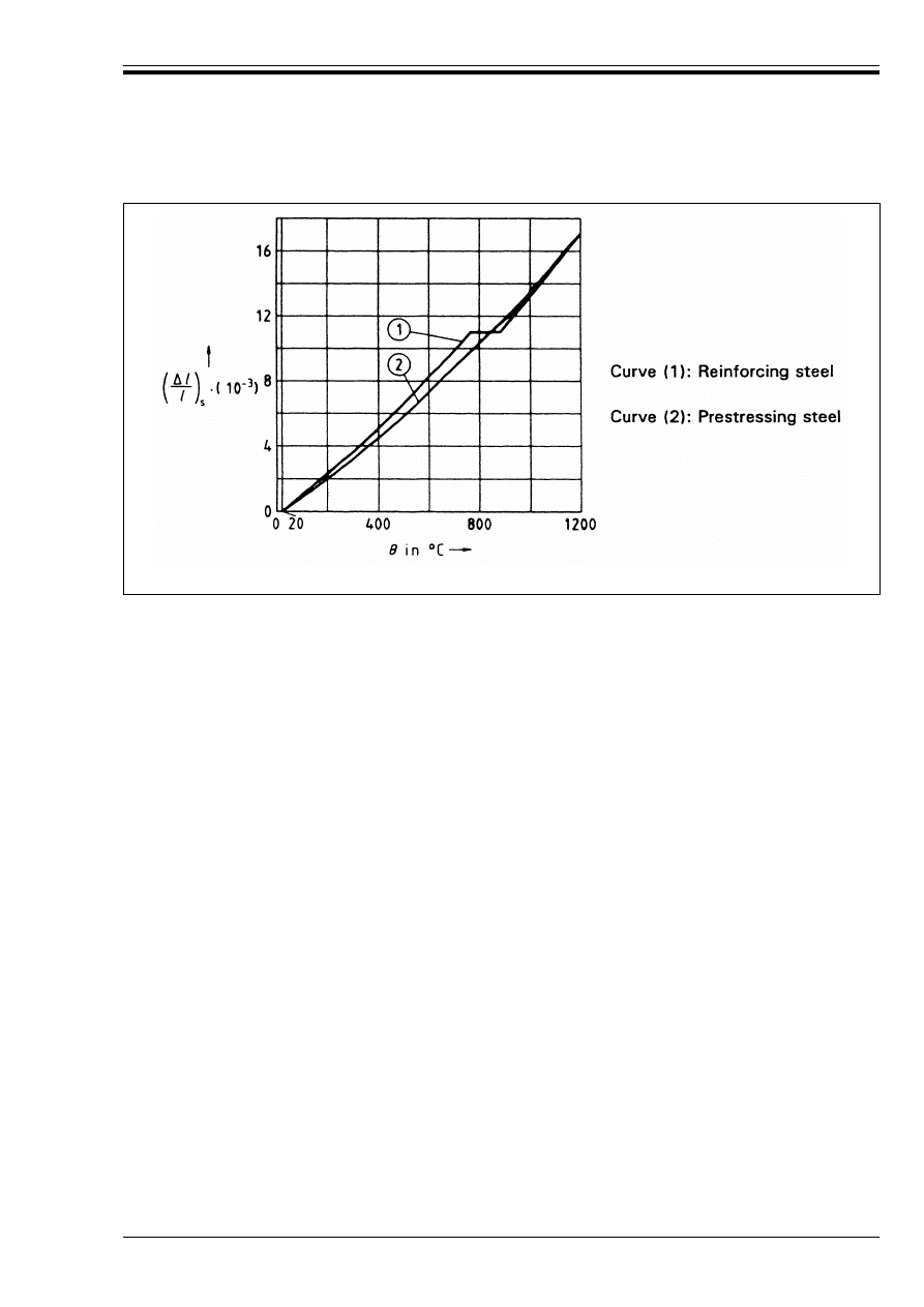
ENV 1992-1-2:1995
© BSI 03-2000
53
If only an approximate answer is required (simple calculation, estimation), the coefficient of thermal
elongation may be used and considered as independent of the steel temperature:
(%l/l)
s
= 14 × 10
–6
G for reinforcing steels
(%l/l)
p
= 12 × 10
–6
G for prestressing steels
(2) The density Ô
s
of reinforcing and prestressing steel should be considered as independent from the steel
temperature:
Ô
s
= 7 850 kg/m
3
(3) Normally in both reinforced and prestressed concrete members, the thermal properties Æ
s
, c
s
, and a
s
, of
steel may be ignored since the influence of the reinforcement on the temperature rise of the cross-section
is of little importance.
A.4 Spalling
(1) Normally explosive spalling is unlikely to occur where the smaller of the cross section dimensions h or
b
in the compressive zones of beams, slabs, walls and columns satisfy the conditions given in Figure A.18.
The compressive stress Ö
c,fi
may be calculated for the combination of actions in the fire situation using the
cross section required by ENV 1992-1-1.
Figure A.17 — Thermal elongation of steel
Licensed copy:Heriot Watt University, 20/04/2004, Uncontrolled Copy, © BSI
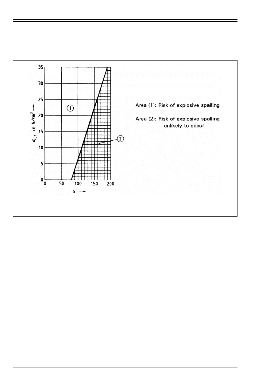
ENV 1992-1-2:1995
54
© BSI 03-2000
Annex B (informative)
Temperature profiles and reduced cross section
B.1 Temperature profiles
(1) Figure B.1 and Figure B.2 provide temperature profiles for beams and slabs. These are conservative
values and are intended for use in determining the temperature of reinforcing bars and prestressing
tendons.
B.2 Cross section and concrete strength
(1) Figure B.3 provides curves which give values of the reduction in concrete compressive strength and
cross section with respect to the thickness of section.
(2) The thickness of section w is assessed as follows:
— For slabs: w = h
— For beams: w =
" b
w
— For columns or walls exposed on one side only: w = width of wall or column
— For columns or walls exposed on two sides: w =
" × width of wall or column
— For columns exposed on four sides: w =
" × the smaller section dimension
(3) The reduction in cross section a
z
is described in 4.3.3, see Figure 4.9.
(4) The reduction in strength k
c
(G
M
) is defined in 3.2.
NOTE a (in mm) is taken as the lesser of h and b.
Figure A.18 — Relationship between Ö
c,fi
and
h (or b) for risk of explosive spalling
for normal weight concrete members
Licensed copy:Heriot Watt University, 20/04/2004, Uncontrolled Copy, © BSI
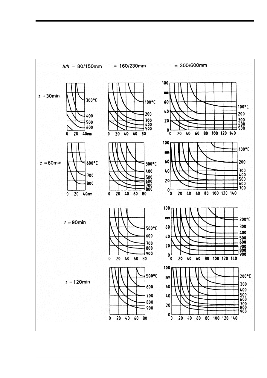
ENV 1992-1-2:1995
© BSI 03-2000
55
Figure B.1 — Temperature profiles for beams
Licensed copy:Heriot Watt University, 20/04/2004, Uncontrolled Copy, © BSI
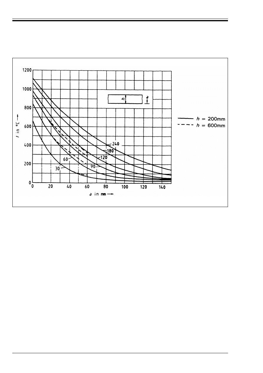
ENV 1992-1-2:1995
56
© BSI 03-2000
Figure B.2 — Temperature profiles for slabs
Licensed copy:Heriot Watt University, 20/04/2004, Uncontrolled Copy, © BSI
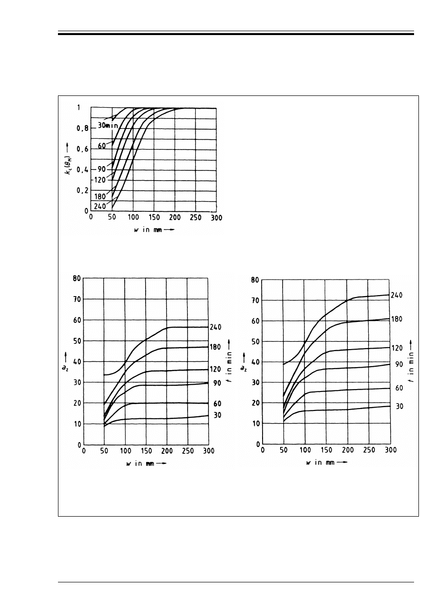
ENV 1992-1-2:1995
© BSI 03-2000
57
w
is assessed as:
* The thickness of a slab,
* The thickness of a one sided exposed wall or
column,
* Half the thickness of the web of a beam,
* Half the thickness of a two sided exposed wall or
column or
* Half the smallest dimension of a four sided exposed
column.
a) Reduction of compression strength for a reduced
cross-section using siliceous aggregate concrete.
b) Reduction in cross-section a
z
of a beam or slab
using siliceous aggregate concrete.
c) Reduction in cross section a
z
of a column or wall
using siliceous aggregate concrete.
NOTE The values for siliceous aggregate concrete are conservative for most other aggregate concretes.
Figure B.3 — Reduction in cross section and concrete strength assuming a standard fire
Licensed copy:Heriot Watt University, 20/04/2004, Uncontrolled Copy, © BSI

ENV 1992-1-2:1995
58
© BSI 03-2000
Annex C (informative)
Simplified method of calculation for beams and slabs
C.1 General
(1) This simplified method of calculation provides an extension to the use of the tabular method for beams
exposed on three sides and slabs, Table 4.4 to Table 4.8. It determines the affect on bending resistance for
situations where the axis distance, a, to bottom reinforcement is less than that required by the tables.
The minimum cross-section dimensions (b, b
w
, h
s
) given in Table 4.4 to Table 4.7 should not be reduced.
This method uses strength reduction factors based on Curve 1 of Figure 3.2 for reinforcing steels
and Figure 3.3 for prestressing steels.
(2) This simplified method may be used to justify reducing the axis distance a. Otherwise the rules given
in 4.2.6.1 to 4.2.6.3 should be followed. This method is not valid for continuous beams where, in the areas
of negative moment, the width b or b
w
is less than 200 mm and the height h
s
is less than 2b, where b is the
value given in Column 3 of Table 4.4.
C.2 Simply supported beams and slabs
(1) It should be verified that
(2) The loading under fire conditions F
d,fi
(kN) may be determined using Equation (2.5).
(3) The maximum fire design moment M
Sd,fi
for predominantly uniformly distributed load may be calculated
using Equation (C.2).
where l
eff
is the effective length of beam or slab.
(4) The moment of resistance M
Rd,fi
for design for the fire situation may be calculated using Equation (C.3).
where:
Y
s
is the partial material factor for steel used in ENV 1992-1-1, (normally taken to be 1,15)
Y
s,fi
is the partial material factor for steel under fire conditions (normally taken to be 1,0)
k
s
(G) is the strength reduction factor of the steel for the given temperature G under the required fire
resistance. G may be taken from Figure B.1 and Figure B.2 for the chosen axis distance
M
Sd
is the applied moment for cold design to ENV 1992-1-1
A
s,prov
is the area of tensile steel provided
A
s,req
is the area of tensile steel required for cold design by ENV 1992-1-1
A
s,prov
/A
s,req
should not be taken as greater than 1,3.
C.3 Continuous beams and slabs
(1) Static equilibrium of flexural moments and shear forces should be ensured for the full length of
continuous beams and slabs under the design fire conditions.
(2) In order to satisfy equilibrium of fire design, moment redistribution from the span to the supports is
permitted where sufficient area of reinforcement is provided over the supports to take the design fire
loading. This reinforcement should extend a sufficient distance into the span to ensure a safe bending
moment envelope.
(3) The moment of resistance M
RdSpan,fi
of the section at the position of maximum sagging moment should
be calculated for fire conditions in accordance with C.2 (4). The maximum free bending moment for applied
loads in the fire situation (F
d,fi
l
eff
/8 for uniformly distributed load) should be fitted to this moment of
resistance M
RdSpan,fi
such that the support moments M
Rd1,fi
and M
Rd2,fi
provide equilibrium as shown
in Figure C.1. This may be carried out by choosing the moment to be supported at one end as equal to or
less than the moment of resistance at that support [calculated using Equation (C.4)], and then calculating
the moment required at the other support.
M
sd,fi
u M
Rd,fi
(C.1)
M
Sd,fi
= F
d,fi
l
eff
/8
(C.2)
M
Rd,fi
= (Y
s
/Y
s,fi
) × k
s
(G) × M
Sd
(A
s,prov
/A
s,req
)
(C.3)
Licensed copy:Heriot Watt University, 20/04/2004, Uncontrolled Copy, © BSI
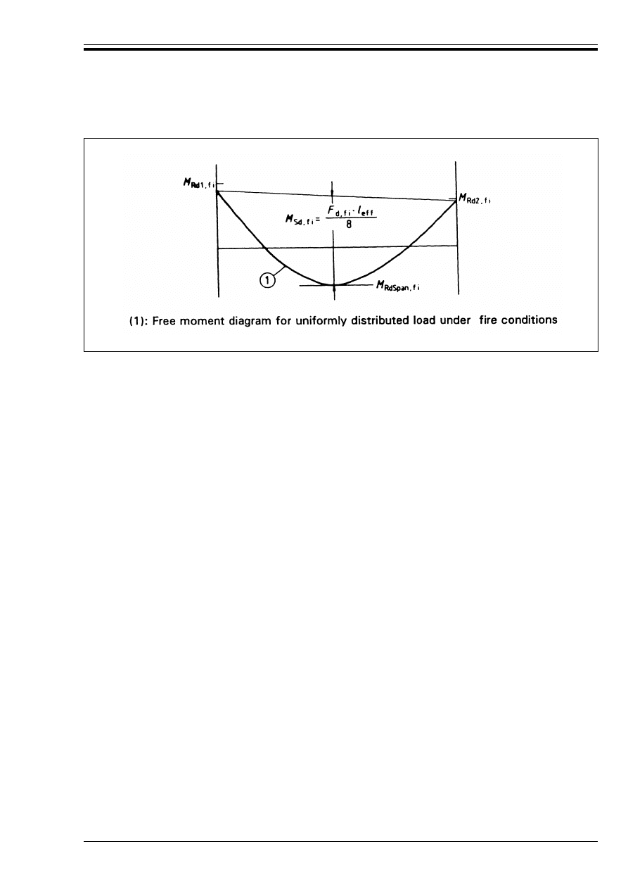
ENV 1992-1-2:1995
© BSI 03-2000
59
(4) In the absence of more rigorous calculations, the moment of resistance at supports for design for the fire
situation may be calculated using Equation (C.4).
where
Y
s
, M
Sd
, Y
s
, Y
s,fi
, A
s,prov
and A
s,req
are defined in C.2
a
is the required average axis distance given in Table 4.5 for beams and Table 4.8, Column 3 for slabs,
d
is the effective depth of section
A
s,prov
/A
s,req
should not be taken as greater than 1,3.
(5) Equation (C.4) is valid where the temperature of the top steel over the supports does not exceed 350 °C
for reinforcing bars nor 100 °C for prestressing tendons.
For higher temperatures M
Rd,fi
should be reduced by k
s
(G) according to Figure 3.2, curve 1, for reinforcing
bars, and by k
p
(G) according to Figure 3.3 for prestressing tendons.
(6) The curtailment length l
bnet,fi
required under fire conditions should be checked. This may be calculated
using Equation (C.5).
where l
bnet
is given in ENV 1992-1-1, Equation (5.4).
The length of bar provided should extend beyond the support to the relevant contra-flexure point as
calculated in C.3 (3) plus a distance equal to l
b net,fi
.
Annex D (informative)
A procedure for assessing the structural response of reinforced concrete
elements under fire
D.1 General
(1) This step by step procedure describes a method for assessing the structural response of reinforced
concrete structures composed of typical elements (beams, columns, slabs and walls) under fire condition,
by means of simple methods of statics.
(2) The effective thermal strain profiles and the consequent behaviour under fire may be estimated with
good approximation, in spite of the uncertainties and the inaccuracy of the physical model used.
D.2 Rules for application
(1) For appropriately chosen durations of the given fire, or corresponding steps of %G (eg. 50 °C or
even 100 °C), the development of surface temperatures on the exposed surfaces and the “temperatures
profiles” of the concrete elements should be determined (see Figure D.1).
Figure C.1 — Positioning the free bending moment diagram
M
Sd,fi
to establish equilibrium
M
Rd,fi
= (Y
s
/Y
s,fi
) M
Sd
(A
s,prov
/A
s,req
) (d – a)/d
(C.4)
l
bnet,fi
= (Y
s
/Y
s,fi
) (Y
c,fi
/Y
c
) l
bnet
(C.5)
Licensed copy:Heriot Watt University, 20/04/2004, Uncontrolled Copy, © BSI
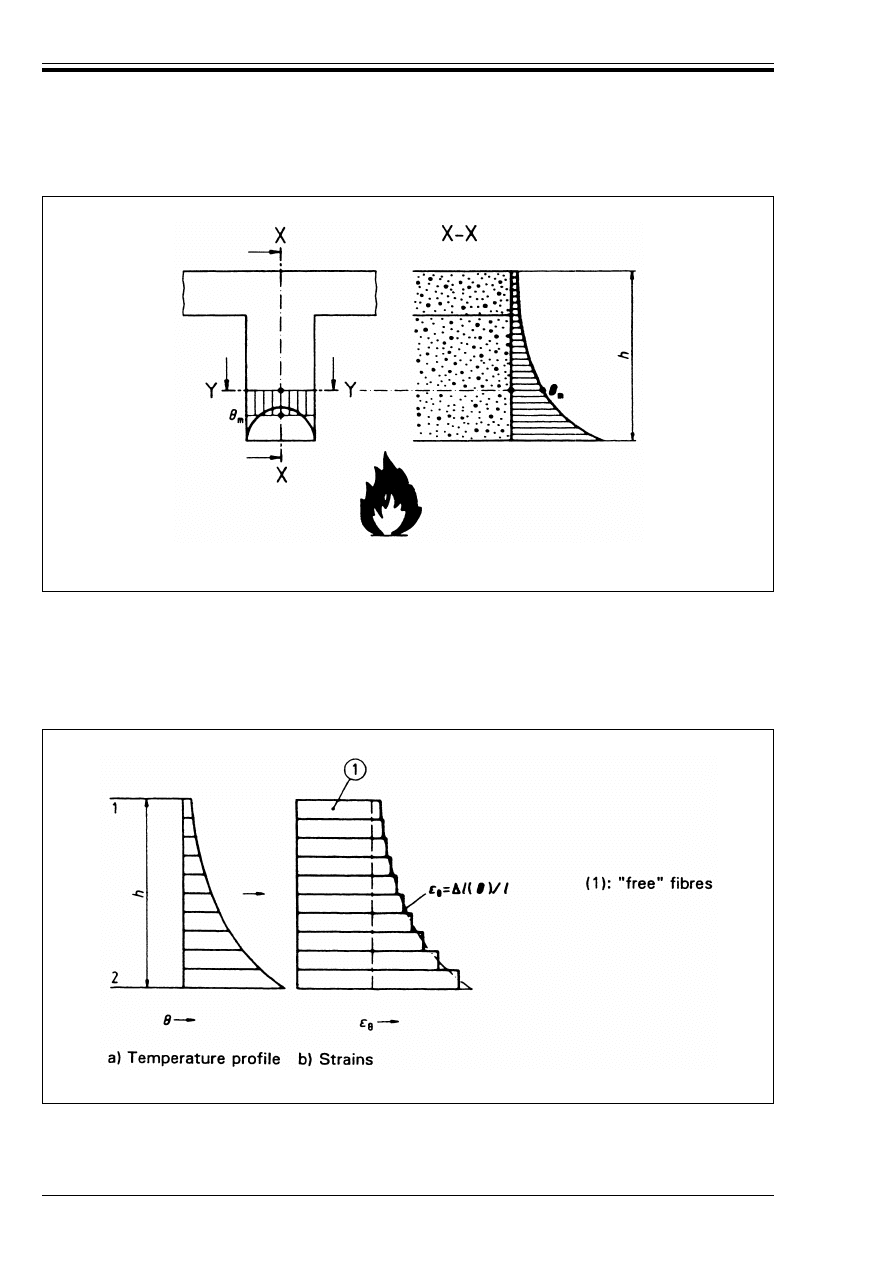
ENV 1992-1-2:1995
60
© BSI 03-2000
(2) For each temperature level, determine the modified elastic modulus E
c
(G
m
) and elongation (%/(G
m
/l)
c
of
concrete (see Annex A).
(3) Assume that the structural element is composed of independent longitudinal fibres (layers), known as
thermo-elements, which are free to move axially. Under fire conditions the temperature profiles induce
thermal elongations which are not distributed linearly, so that sections do not remain plane
(see Figure D.2).
Figure D.1 — Temperature profiles in concrete elements. G
m
is the average
temperature along a horizontal section y-y
Figure D.2 — Layers of thermo-elements assumed free to move axially
Licensed copy:Heriot Watt University, 20/04/2004, Uncontrolled Copy, © BSI
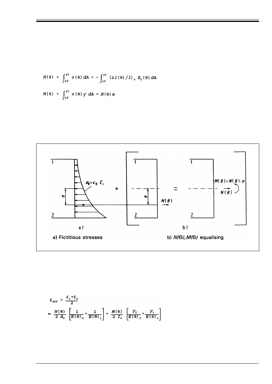
ENV 1992-1-2:1995
© BSI 03-2000
61
(4) The equivalent action effects N(G) and M(G) are then determined by applying a hypothetical stress Ö(G)
to each layer, sufficient to cause an equal and opposite strain to its thermal strain. The forces from each
layer are summed over the height of the section to give N(G), e and hence M(G) (see Figure D.3).
where:
E
c
(G) and (%l(G)/l)
c
are defined in D.2 (see also Annex A),
h
is the height of the cross section,
y
is the distance of a thermo-element from the element axis and
y
1
, and y
2
are the distances of the upper and lower thermo-elements from the member axis.
(5) The residual internal stresses are found by combining the hypothetical stresses Ö(G) and the stresses
due to N(G) and M(G), as shown in Figure D.4.
(6) The effective imposed strains are equal to the sum of the thermal strains of the thermo-elements
(see Figure D.2) and the mechanical strains due to the final internal stresses (see Figure D.4).
Hence:
a) The mean axial strain imposed on the cross-section is given by the expression:
(D.1)
(D.2)
Figure D.3 — Hypothetical and equalising forces
(D.3)
Licensed copy:Heriot Watt University, 20/04/2004, Uncontrolled Copy, © BSI
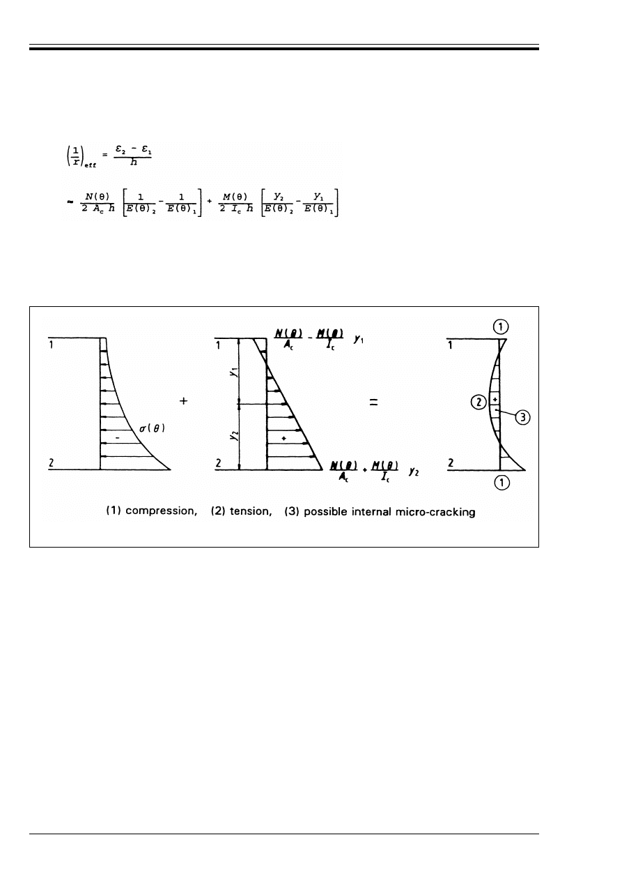
ENV 1992-1-2:1995
62
© BSI 03-2000
b) The curvature, i.e. the mean strain gradient imposed on the cross-section is given by the expression:
where:
A
c
is the area of the cross-section,
l
c
is the moment of inertia of the cross-section, subscripts 1 and 2 refer respectively to the upper and
lower fibre of the cross-section.
(7) If the member is axially unrestrained (i.e. free to expand) the mean axial strain imposed on the
cross-section [Equation (D.3)] will result in an overall axial deformation.
If the member is free to rotate the mean strain gradient imposed on the cross-section [Equation (D.4)]
will result in an overall curvature of the section.
The resulting axial elongations, rotations and deflections of such unrestrained building elements do not
produce any further external forces.
(8) In the general case of statically indeterminate structural elements or sub-assemblies, the mean strains
and curvatures developed under elevated temperatures, lead to a modification of axial deformations,
deflections and rotations, as well as to redistribution of action-effects.
The relevant analysis can be carried out by means of conventional methods of statics, based on
moment/curvature and axial-force/elongation diagrams of selected cross-sections for a given temperature
profile. Such diagrams provide all the necessary values of (variable) stiffness for every situation and
corresponding level of action-effects.
(9) It is also possible to evaluate the safety margin (against flexural or shear failure) and the ductility at
critical sections of structural elements. In order to do this, the properties of concrete, steel and their bond
characteristics should be modified to take account of the corresponding internal temperature levels.
D.3 Possible further simplifications
(1) In order to overcome the laborious procedure of setting up thermo-elements and calculating the internal
stresses, practical diagrams may be used to obtain an approximate estimation of the effective thermal
deformations (mean elongation and curvature) assuming sections remain plane under fire conditions.
(D.4)
Figure D.4 — Final internal self-equilibrating stresses
Licensed copy:Heriot Watt University, 20/04/2004, Uncontrolled Copy, © BSI
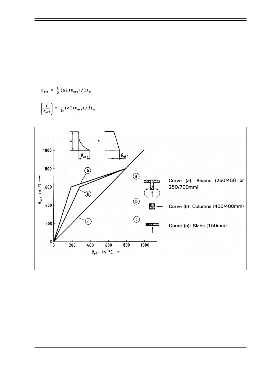
ENV 1992-1-2:1995
© BSI 03-2000
63
(2) For certain shapes and dimensions of typical cross-sections, practical diagrams may be prepared using
an equivalent linear temperature distribution G
eff
at the exposed faces of the considered cross-section,
instead of the actual temperature distribution G
act
. An example of such a practical diagram is given
in Figure D.5. This is only valid for cross-sections similar to those shown. Using such diagrams, the
redistribution of action-effects and the modification of deformations of reinforced concrete elements during
fire may be analyzed using normal loads with effective imposed deformations.
(D.5)
(D.6)
Figure D.5 — Equivalent temperature values G
eff
for typical reinforced concrete
sections exposed to a standard fire
Licensed copy:Heriot Watt University, 20/04/2004, Uncontrolled Copy, © BSI

DD ENV
1992-1-2:1996
BSI
389 Chiswick High Road
London
W4 4AL
BSI — British Standards Institution
BSI is the independent national body responsible for preparing
British Standards. It presents the UK view on standards in Europe and at the
international level. It is incorporated by Royal Charter.
Revisions
British Standards are updated by amendment or revision. Users of
British Standards should make sure that they possess the latest amendments or
editions.
It is the constant aim of BSI to improve the quality of our products and services.
We would be grateful if anyone finding an inaccuracy or ambiguity while using
this British Standard would inform the Secretary of the technical committee
responsible, the identity of which can be found on the inside front cover.
Tel: 020 8996 9000. Fax: 020 8996 7400.
BSI offers members an individual updating service called PLUS which ensures
that subscribers automatically receive the latest editions of standards.
Buying standards
Orders for all BSI, international and foreign standards publications should be
addressed to Customer Services. Tel: 020 8996 9001. Fax: 020 8996 7001.
In response to orders for international standards, it is BSI policy to supply the
BSI implementation of those that have been published as British Standards,
unless otherwise requested.
Information on standards
BSI provides a wide range of information on national, European and
international standards through its Library and its Technical Help to Exporters
Service. Various BSI electronic information services are also available which give
details on all its products and services. Contact the Information Centre.
Tel: 020 8996 7111. Fax: 020 8996 7048.
Subscribing members of BSI are kept up to date with standards developments
and receive substantial discounts on the purchase price of standards. For details
of these and other benefits contact Membership Administration.
Tel: 020 8996 7002. Fax: 020 8996 7001.
Copyright
Copyright subsists in all BSI publications. BSI also holds the copyright, in the
UK, of the publications of the international standardization bodies. Except as
permitted under the Copyright, Designs and Patents Act 1988 no extract may be
reproduced, stored in a retrieval system or transmitted in any form or by any
means – electronic, photocopying, recording or otherwise – without prior written
permission from BSI.
This does not preclude the free use, in the course of implementing the standard,
of necessary details such as symbols, and size, type or grade designations. If these
details are to be used for any other purpose than implementation then the prior
written permission of BSI must be obtained.
If permission is granted, the terms may include royalty payments or a licensing
agreement. Details and advice can be obtained from the Copyright Manager.
Tel: 020 8996 7070.
Licensed copy:Heriot Watt University, 20/04/2004, Uncontrolled Copy, © BSI
Document Outline
Wyszukiwarka
Podobne podstrony:
Eurocode 2 Design of concrete structures Part 2
Eurocode 2 Design of concrete structures part4
Eurocode 2 Design of concrete structures Part 1 3
Eurocode 2 Design of concrete structures part4
Eurocode 2 Design of concrete structures Part 2
Eurocode 2 Part 3 2006 UK NA Design of concrete structures Liquid retaining and containing struc
Eurocode 2 Part 1 1 2004 NA UK Design of concrete structures General rules and rules for buildin
Eurocode 2 Part 3 2006 Design of concrete structures Liquid retaining and containing structures
Eurocode 2 Part 2 2004 UK NA Design of concrete structures Concrete bridges Design and detailin
Eurocode 2Design of concrete structures Part 1 1
Eurocode 5 EN 1995 1 1 Design Of Timber Structures Part 1 1 General Rules
Eurocode 5 EN 1995 1 1 Design Of Timber Structures Part 1 1 General Rules
Eurocode 6 Part 1 2 1996 2005 Design of Masonry Structures General Rules Structural Fire Design
Eurocode 6 Part 2 1996 2006 Design of Masonry Structures Design Considerations, Selection of Mat
Eurocode 3 Part 1 7 2009 Design of Steel Structures Plated Structures Subject to Out of Plane Loa
więcej podobnych podstron