
Junos for Security Platforms
1
Lab 2
Firewall User Authorization & Screen Options
Overview
In first part of this lab, you will implement firewall user authentication. You will enable FTP access
between networks and secure the access with authentication. You will test and monitor the effects of
firewall user authentication. The configuration tasks performed within this lab and subsequent labs
will build upon one another. The second part of this lab you will implement the Junos operating
system SCREEN options. You will set up various SCREENs to protect your assigned device from
suspicious or malicious traffic entering your device from the untrust zone.
All devices are connected to a common management network which facilitates access to the CLI.
These exercises assume you already have some basic understanding of the JUNOS CLI interfaces
and you have attended the IJS and JRE training.
Note that your lab login (password given to you separately) grants you all permissions needed to
complete this lab; however, some restrictions have been made to prevent loss of connectivity to the
devices. Please be careful, and have fun!
By completing this lab, you will perform the following tasks:
Define clients within an access profile.
Create a default client group and associate clients with the group.
Configure firewall user authentication parameters.
Add and alter security policies that have an extended permit action specifying firewall user
authentication.
Define various SCREEN options (called ids-options).
Associate the SCREEN with a security zone.
Monitor the effects of your configuration
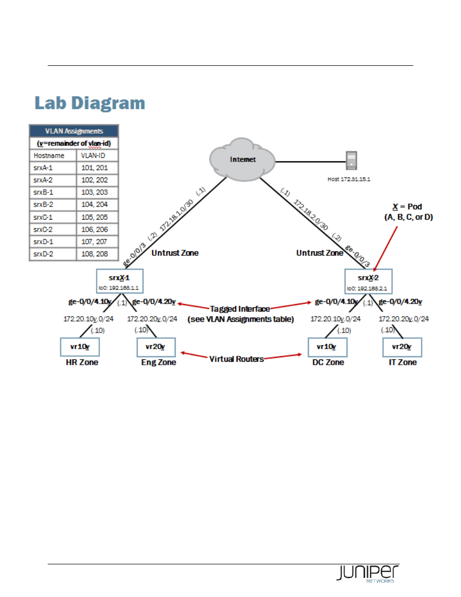
Please refer to the next page lab diagram to perform this exercise:
Junos for Security Platforms
2
Lab Diagram

Junos for Security Platforms
3
Key Commands
Key operational mode commands used in this lab include the following:
show security firewall-authentication users
show log messages
show security screen statistics
Part 1:
Configuring Firewall User Authentication
In this lab part, you will define clients within an access profile, create a default client group and
associate clients with the group, and configure firewall user authentication parameters.
Step 1.1
Restore your POD’s devices to the state they should be after finished LAB 1. Remember that these
devices are used by multiple students every day in various virtual training activities and always
before a new lab session resetted to a default state. To get started from point where you finished the
last lab you need to load a saved configuration file using the command
load override
/var/home/instructor/JSEC_Virtual/lab2_start. Do not forget to commit your
configuration after successful load operation.
[edit]
lab@host1-d# load override /var/home/instructor/JSEC_Virtual/lab2_start
load complete
[edit]
lab@host1-d# commit
commit complete
Step 1.2
Enter configuration mode and navigate to the [edit access] hierarchy.
lab@host1-d> configure
Entering configuration mode
[edit]
lab@host1-d# edit access
[edit access]
lab@host1-d#

Junos for Security Platforms
4
Step 1.3
Create an access profile named ftp-users. Configure two clients named walter and nancy
with passwords of walter123 and nancy123, respectively.
[edit access]
lab@host1-d# edit profile ftp-users
[edit access profile ftp-users]
lab@host1-d# set client walter firewall-user password walter123
[edit access profile ftp-users]
lab@host1-d# set client nancy firewall-user password nancy123
Step 1.4
Associate all clients in the ftp-users profile with a client group named ftp-group.
[edit access]
lab@host1-d# set profile ftp-users session-options client-group ftp-group
[edit access]
lab@host1-d# show
profile ftp-users {
client nancy {
firewall-user {
password "$9$BT.RSevMXbs4IEgJGUHkp0ORyl"; ## SECRET-DATA
}
}
client walter {
firewall-user {
password "$9$O1G0RrvW87bs4xNs4JZq.uOBRylM8X"; ## SECRET-DATA
}
}
session-options {
client-group ftp-group;
}
}
Question: What method of associating clients with client groups requires the least amount
of keystrokes for this scenario?
Answer: You can specify client groups individually with each client. However when all
clients within an access profile have the same requirements, the most efficient method
would be to assign a default client group as shown in the example.

Junos for Security Platforms
5
Step 1.5
Associate the ftp-users profile with pass-through firewall user authentication.
[edit access]
lab@host1-d# edit firewall-authentication
[edit access firewall-authentication]
lab@host1-d# set pass-through default-profile ftp-users
Step 1.6
Change the current FTP policy, which rejects outgoing FTP from zones hr and dc to zone untrust. Instead
of rejecting the traffic you must now permit FTP in that policy .
Navigate to [edit security policies from-zone hr to-zone untrust] hierarchy and
change the policy deny-ftp-hr to permit FTP traffic.
[edit access firewall-authentication]
lab@host1-d# top edit security policies from-zone hr to-zone untrust
[edit security policies from-zone hr to-zone untrust]
lab@host1-d# show
policy deny-ftp-hr {
match {
source-address any;
destination-address any;
application junos-ftp;
}
then {
reject;
}
}
policy internet-hr {
match {
source-address vr107;
destination-address any;
application any;
}
then {
permit;
}
}
[edit security policies from-zone hr to-zone untrust]
lab@host1-d# set policy deny-ftp-hr then permit
Step 1.7
Now add FTP into the internal-apps application set to allow FTP inbound from zone untrust to zones
hr and dc respectively in your POD’s devices.

Junos for Security Platforms
6
[edit security policies from-zone hr to-zone untrust]
lab@host1-d# top edit applications application-set internal-apps
[edit applications application-set internal-apps]
lab@host1-d# set application junos-ftp
[edit applications application-set internal-apps]
lab@host1-d# show
application hr-gizmo;
application junos-telnet;
application junos-ping;
application junos-ftp;
Step 1.8
Last thing you need to do now is to add the firewall authentication snippet on your policy allowing FTP
from zone untrust to zone hr and dc respectively.
[edit applications application-set internal-apps]
lab@host1-d# top edit security policies from-zone untrust to-zone hr policy dc-to-
hr
[edit security policies from-zone untrust to-zone hr policy dc-to-hr]
lab@host1-d# set then permit firewall-authentication pass-through client-match
ftp-group
[edit security policies from-zone untrust to-zone hr policy dc-to-hr]
lab@host1-d# commit and-quit
commit complete
Exiting configuration mode
lab@host1-d>
Step 1.9
Repeat steps 1.1 - 1.8 in your POD’s second device.

Junos for Security Platforms
7
Part 2:
Verifying and Monitoring Firewall User Authentication
I In this lab part, you will verify the results of your configuration through testing. You will also monitor
firewall user authentication using traceoptions and operational mode commands.
Step 2.1
Open a separate Telnet session to the virtual router attached to your team device. You need to open a
new ssh session to the Jump Server and from there establish a telnet session to the virtual device.
Observe that you have only very limited access to the virtual device and should follow the lab
instructions as written very strictly.
Use the login credentials from the table here below.
Virtual Router Login Details
Student Device
User Name
Password
srxA-1
a1
lab123
srxA-2
a2
lab123
srxB-1
b1
lab123
srxB-2
b2
lab123
srxC-1
c1
lab123
srxC-2
c2
lab123
srxD-1
d1
lab123
srxD-2
d2
lab123
[timo@js2 ~]$ telnet 10.210.14.139
Trying 10.210.14.139...
Connected to j2350.lab2.cavellgroup.com (10.210.14.139).
Escape character is '^]'.
vr-device (ttyp0)
login: d1
Password:
--- JUNOS 9.2R1.10 built 2008-08-07 06:45:07 UTC
NOTE: This router is divided into many virtual routers used by different teams.
Please only configure your own virtual router.
You must use 'configure private' to configure this router.
d1@vr-device>
Step 2.2
Initiate an FTP session between the virtual router associated with the
hr zone and the virtual router
associated with the
dc zone. Note that the ftp command is hidden and does not auto-complete.
Remember to source the command from the appropriate routing-instance. When prompted for
firewall user authentication, use the credentials you created for the user nancy.

Junos for Security Platforms
8
d1@vr-device> ftp 172.20.108.10 routing-instance vr107
Connected to 172.20.108.10.
220 vr-device FTP server (Version 6.00LS) ready.
Name (172.20.108.10:d1): nancy
331 Password required for nancy.
Password:
530 Login incorrect.
ftp: Login failed.
ftp> bye
d1@vr-device>
Question: Was the authentication successful? What behavior did you observe?
Answer: Although the FTP session failed, authentication was indeed successful. In the
Junos OS, for FTP sessions, the observed behavior is expected. For FTP traffic only, the
session needs to be re-initiated after performing firewall authentication.
Step 2.3
Return to the session opened to your assigned device and issue the
show security firewall-
authentication users command.
lab@host2-d> show security firewall-authentication users
Firewall authentication data:
Total users in table: 1
Id Source Ip Src zone Dst zone Profile Age Status User
1 172.20.107.10 untrust dc ftp-user 1 Success nancy
Question: What does the output for this command indicate?
Answer: The output indicates that nancy successfully authenticated. If you do not see
the user nancy in the output, check your configuration.
Step 2.4
Return to the session opened to the vr-device and attempt the FTP session again. Log in to the FTP
server using your assigned username and password for the vr-device.

Junos for Security Platforms
9
d1@vr-device> ftp 172.20.108.10 routing-instance vr107
Connected to 172.20.108.10.
220 vr-device FTP server (Version 6.00LS) ready.
Name (172.20.108.10:d1): d1
331 Password required for d1.
Password:
230 User d1 logged in.
Remote system type is UNIX.
Using binary mode to transfer files.
ftp> bye
d1@vr-device>
____________________________ Note __________________________
To manage to log in via the FTP you have to make sure you log in with your valid
user ID not too long after you have made the firewall authentication. Remember
the successful authentication allows now FTP from the authenticated IP address.
Should your FTP login fail repeat the authentication with user nancy and then try
again.
__________________________________________________________________
Question: Were you able to successfully establish an FTP session?
Answer: As shown in the output, you should now be able to successfully establish the
FTP session.
Step 2.5
Exit your current FTP sessions if not already finished.
Return to the session opened on your assigned student device and clear the entries in the firewall
authentication users table, if any exist.
lab@host2-d> show security firewall-authentication users
Firewall authentication data:
Total users in table: 1
Id Source Ip Src zone Dst zone Profile Age Status User
1 172.20.107.10 untrust dc ftp-user 3 Success nancy
lab@host2-d> clear security firewall-authentication users
lab@host2-d> show security firewall-authentication users
Firewall authentication data:
Total users in table: 0

Junos for Security Platforms
10
Step 2.6
Return to the session opened to the vr-device and attempt another FTP session between the
hr and
dc security zones. When you are prompted for the firewall authentication, use a username of john
and a password of doe.
d1@vr-device> ftp 172.20.108.10 routing-instance vr107
Connected to 172.20.108.10.
220 Firewall User Authentication Ready
Name (172.20.108.10:d1): john
331 Password Required
Password:
421 Service not available, remote server has closed connection.
ftp: Login failed.
ftp: No control connection for command.
ftp> bye
Step 2.7
Return to your device and issue the show security firewall-authentication users
command.
lab@host2-d> show security firewall-authentication users
Firewall authentication data:
Total users in table: 1
Id Source Ip Src zone Dst zone Profile Age Status User
2 172.20.107.10 untrust dc ftp-user 3 Failed john
Question: Are any failed authentication attempts listed in the outputs?
Answer: The outputs may vary, but provided the remote team within your pod attempted
an FTP session with the username john, at least one failed attempt should be listed.
Step 2.8
View the firewall user authentication entries in your data plane log by issuing the
show log
messages | match RT_AUTH command.
lab@host2-d> show log messages | match RT_AUTH
Feb 13 09:57:43 host2-d RT_AUTH: FWAUTH_FTP_USER_AUTH_ACCEPTED: User nancy of
group ftp-group at 172.20.107.10 is accepted.
Feb 13 10:18:57 host2-d RT_AUTH: FWAUTH_FTP_USER_AUTH_FAIL: User john at
172.20.107.10 is rejected.

Junos for Security Platforms
11
Question: What additional information can you derive from the data plane security log?
Answer: The security log shows the authentication attempts were made using FTP as
well as the source address, username, and firewall authentication action.

Junos for Security Platforms
12
Part 3:
Configuring SCREEN Protection
In this lab part, you will configure SCREEN protection.
Step 3.1
Enter configuration mode and navigate to the [edit security screen] hierarchy.
lab@host1-d> configure
Entering configuration mode
[edit]
lab@host1-d# edit security screen
[edit security screen]
lab@host1-d#
Step 3.2
Create a SCREEN that blocks ICMP packets larger than 1024 bytes. Name the SCREEN
internet-protect.
[edit security screen]
lab@host1-d# set ids-option internet-protect icmp large
Step 3.3
Within the same SCREEN option, configure the SCREEN to block ICMP fragments.
[edit security screen]
lab@host1-d# set ids-option internet-protect icmp fragment
Question: Can you recall a common type of attack blocked by this SCREEN from the
class discussion?
Answer: Enabling protection from ICMP packets larger than 1024 bytes and from
fragmented ICMP packets provides protection from ICMP Ping of Death attacks. An ICMP
Ping of Death attack occurs when ping packets are sent to a host in excess of the
maximum IP packet size of 65,535 bytes. These packets are typically fragmented.

Junos for Security Platforms
13
Step 3.4
Add protection from packets that are using the IP Record Route option to the internet-protect
SCREEN.
[edit security screen]
lab@host1-d# set ids-option internet-protect ip record-route-option
Step 3.5
Add additional protection that limits the number of sessions to the same destination IP address to a
maximum of one session. Activate the configuration changes by issuing the
commit command.
[edit security screen]
lab@host1-d# set ids-option internet-protect limit-session destination-ip-based 1
[edit security screen]
lab@host1-d# show
ids-option internet-protect {
icmp {
fragment;
large;
}
ip {
record-route-option;
}
limit-session {
destination-ip-based 1;
}
}
[edit security screen]
lab@host1-d# commit and-quit
commit complete
Exiting configuration mode
lab@host1-d>

Junos for Security Platforms
14
Part 4:
Verifying SCREEN Protection
In this lab part, you will verify the results of your SCREEN configuration.
Step 4.1
Open a separate Telnet session to the virtual router attached to your team device. You need to open a
new ssh session to the Jump Server and from there establish a telnet session to the virtual device.
Observe that you have only very limited access to the virtual device and should follow the lab
instructions as written very strictly.
Use the login credentials from the table here below.
Virtual Router Login Details
Student Device
User Name
Password
srxA-1
a1
lab123
srxA-2
a2
lab123
srxB-1
b1
lab123
srxB-2
b2
lab123
srxC-1
c1
lab123
srxC-2
c2
lab123
srxD-1
d1
lab123
srxD-2
d2
lab123
[timo@js2 ~]$ telnet 10.210.14.139
Trying 10.210.14.139...
Connected to j2350.lab2.cavellgroup.com (10.210.14.139).
Escape character is '^]'.
vr-device (ttyp0)
login: d1
Password:
--- JUNOS 9.2R1.10 built 2008-08-07 06:45:07 UTC
NOTE: This router is divided into many virtual routers used by different teams.
Please only configure your own virtual router.
You must use 'configure private' to configure this router.
d1@vr-device>
Step 4.2
Initiate a ping between the virtual router in the hr zone and the virtual router in the dc zone.

Junos for Security Platforms
15
d1@vr-device> ping 172.20.108.10 routing-instance vr107 count 5
PING 172.20.108.10 (172.20.108.10): 56 data bytes
--- 172.20.108.10 ping statistics ---
5 packets transmitted, 0 packets received, 100% packet loss
Question: Was the ping successful? If not, why?
Answer: According to the output it was not. Reason for this is, even though junos-ping
is allowed in the internal-apps group, there is a firewall authentication rule in place in
the policy permitting traffic from zone
untrust to zone hr and dc respectively.
Step 4.3
Return to the session to your SRX device and deactivate the configuration section where the firewall
authentication takes place. Do this in both of your POD’s devices.
[edit]
lab@host1-d# edit security policies from-zone untrust to-zone hr policy dc-to-hr
[edit security policies from-zone untrust to-zone hr policy dc-to-hr]
lab@host1-d# show
match {
source-address vr108;
destination-address vr107;
application internal-apps;
}
then {
permit {
firewall-authentication {
pass-through {
client-match ftp-group;
}
}
}
}
[edit security policies from-zone untrust to-zone hr policy dc-to-hr]
lab@host1-d# deactivate then permit firewall-authentication
[edit security policies from-zone untrust to-zone hr policy dc-to-hr]
lab@host1-d# show
match {
source-address vr108;
destination-address vr107;
application internal-apps;
}
then {
permit {
inactive: firewall-authentication {

Junos for Security Platforms
16
pass-through {
client-match ftp-group;
}
}
}
}
[edit security policies from-zone untrust to-zone hr policy dc-to-hr]
lab@host1-d# commit and-quit
commit complete
Exiting configuration mode
lab@host1-d>
Step 4.4
Initiate a ping between the virtual router in the hr zone and the virtual router in the dc zone.
d1@vr-device> ping 172.20.107.10 routing-instance vr108 count 5
PING 172.20.107.10 (172.20.107.10): 56 data bytes
64 bytes from 172.20.107.10: icmp_seq=0 ttl=61 time=5.060 ms
64 bytes from 172.20.107.10: icmp_seq=1 ttl=61 time=4.342 ms
64 bytes from 172.20.107.10: icmp_seq=2 ttl=61 time=11.105 ms
64 bytes from 172.20.107.10: icmp_seq=3 ttl=61 time=4.648 ms
64 bytes from 172.20.107.10: icmp_seq=4 ttl=61 time=9.365 ms
--- 172.20.107.10 ping statistics ---
5 packets transmitted, 5 packets received, 0% packet loss
round-trip min/avg/max/stddev = 4.342/6.904/11.105/2.784 ms
Question: Was the ping successful? What size does an ICMP echo request packet use by
request?
Answer: The ping should succeed as shown in the output. An ICMP echo request
consists of a data size of 56 bytes, plus an ICMP header size of 8 bytes. The output does
not show the additional Ethernet overhead of 20 bytes.
Step 4.4
Issue the same ping request again, but this time specify a size of 1100 bytes. This size is larger than
1024 bytes and should trigger the ICMP large SCREEN option, provided the remote team properly
configured it on their device.
d1@vr-device> ping 172.20.107.10 routing-instance vr108 count 5 size 1100
PING 172.20.107.10 (172.20.107.10): 1100 data bytes
1108 bytes from 172.20.107.10: icmp_seq=0 ttl=61 time=4.362 ms
1108 bytes from 172.20.107.10: icmp_seq=1 ttl=61 time=4.341 ms
1108 bytes from 172.20.107.10: icmp_seq=2 ttl=61 time=5.404 ms

Junos for Security Platforms
17
1108 bytes from 172.20.107.10: icmp_seq=3 ttl=61 time=4.534 ms
1108 bytes from 172.20.107.10: icmp_seq=4 ttl=61 time=4.335 ms
--- 172.20.107.10 ping statistics ---
5 packets transmitted, 5 packets received, 0% packet loss
round-trip min/avg/max/stddev = 4.335/4.595/5.404/0.411 ms
Question: What is the result of the ping operation with a specified size of 1100 bytes? Are
the results expected?
Answer: The output indicates the ping was successful and something is amiss regarding
the SCREEN options configuration. The results are expected. Although the configuration
contains the appropriate SCREEN options, the SCREEN options have not yet been
applied to a security zone.
Step 4.5
Return to the session opened to your assigned device. Apply the internet-protect SCREEN
option to the
untrust security zone. Commit your configuration and exit configuration mode.
Do not forget to configure this on both of your POD’s devices!
lab@host1-d> configure
Entering configuration mode
[edit]
lab@host1-d# edit security zones security-zone untrust
[edit security zones security-zone untrust]
lab@host1-d# set screen internet-protect
[edit security zones security-zone untrust]
lab@host1-d# show
address-book {
address vr108 172.20.108.0/24;
address vr208 172.20.208.0/24;
address host2-d 172.18.2.0/30;
address internet-host 172.31.15.1/32;
}
screen internet-protect;
interfaces {
ge-0/0/3.0;
}
[edit security zones security-zone untrust]
lab@host1-d# commit and-quit
commit complete
Exiting configuration mode

Junos for Security Platforms
18
Step 4.6
Return to the session opened on the vr-device and repeat the ping command between the virtual
routers associated with the hr and dc security zones. Once again, specify a size of 1100 bytes.
d1@vr-device> ping 172.20.107.10 routing-instance vr108 count 5 size 1100
PING 172.20.107.10 (172.20.107.10): 1100 data bytes
--- 172.20.107.10 ping statistics ---
5 packets transmitted, 0 packets received, 100% packet loss
Question: What is the result of the ping operation with a specified size of 1100 bytes? Are
the results expected?
Answer: The output indicates the ping was not successful. This behavior is expected and
demonstrates the ICMP large SCREEN option is working as designed.
Step 4.7
Determine the physical maximum transmission unit (MTU) of your virtual router’s interface
(associated with the hr or dc zone) that connects to your assigned device by issuing the
show
interfaces ge-0/0/1 media | match mtu command.
d1@vr-device> show interfaces ge-0/0/1 media | match mtu
Link-level type: Ethernet, MTU: 1518, Speed: 1000mbps, MAC-REWRITE Error: None,
Question: What is the physical MTU size of the interface?
Answer: The output indicates the physical MTU is 1518 bytes.
Step 4.8
Issue another ping between the virtual routers associated with the hr and dc security zones. This
time specify a size of 2000 bytes, ensuring ICMP packet fragmentation occurs. Do not forget to
source the ping from the proper routing-instance!
d1@vr-device> ping 172.20.107.10 routing-instance vr108 count 5 size 2000
PING 172.20.107.10 (172.20.107.10): 2000 data bytes
--- 172.20.107.10 ping statistics ---
5 packets transmitted, 0 packets received, 100% packet loss

Junos for Security Platforms
19
Question: What is the result of the ping specifying a size of 2000 bytes? Are the results
expected?
Answer: The output indicates the ping was not successful. This behavior is expected and
demonstrates the ICMP fragment SCREEN option is working as designed.
Step 4.9
Issue another ping between the virtual routers associated with the hr and dc security zones. This
time specify the
record-route option.
d1@vr-device> ping 172.20.107.10 routing-instance vr108 count 5 record-route
PING 172.20.107.10 (172.20.107.10): 56 data bytes
--- 172.20.107.10 ping statistics ---
5 packets transmitted, 0 packets received, 100% packet loss
Question: What is the result of the ping specifying the record-route option? Are the
results expected?
Answer: The output indicates the ping was not successful. This behavior is expected and
demonstrates the ICMP record route SCREEN option is working as designed.
Step 4.10
Within your current vr-device Telnet session, open a new Telnet session to the remote virtual router
associated with the
hr or dc security zone. Use the same login credentials as used for your current
vr-device Telnet session.
d1@vr-device> telnet 172.20.107.10 routing-instance vr108
Trying 172.20.107.10...
Connected to 172.20.107.10.
Escape character is '^]'.
vr-device (ttyp2)
login: d1
Password:
--- JUNOS 9.2R1.10 built 2008-08-07 06:45:07 UTC
NOTE: This router is divided into many virtual routers used by different teams.
Please only configure your own virtual router.

Junos for Security Platforms
20
You must use 'configure private' to configure this router.
d1@vr-device>
Step 4.11
Open a new, separate Telnet session to the vr-device and from there open another telnet session to the
remote virtual router associated with the
hr or dc security zone.
d1@vr-device> telnet 172.20.107.10 routing-instance vr108
Trying 172.20.107.10...
telnet: connect to address 172.20.107.10: Operation timed out
telnet: Unable to connect to remote host
d1@vr-device>
Question: Did the second Telnet session between the remote virtual routers successfully
establish? Is the result expected?
Answer: As indicated in the output, the Telnet session is unable to establish. This result is
expected and demonstrates the destination-based session limit is in effect.
____________________________ Note __________________________
Leave both Telnet sessions opened to the vr-device for the time being. You
return to these sessions in the next part of the lab.
__________________________________________________________________

Junos for Security Platforms
21
Part 5:
Monitoring SCREEN Protection
In this lab part, you will monitor the effects of SCREEN protection. You must coordinate some of the
monitoring efforts with both SRXs in your pod.
Step 5.1
Return to the terminal session opened to your assigned device. Issue the
show security screen
statistics zone untrust command and review the output..
lab@host1-d> show security screen statistics zone untrust
Screen statistics:
IDS attack type Statistics
ICMP flood 0
UDP flood 0
TCP winnuke 0
TCP port scan 0
ICMP address sweep 0
IP tear drop 0
TCP SYN flood 0
IP spoofing 0
ICMP ping of death 0
IP source route option 0
TCP land attack 0
TCP SYN fragment 0
TCP no flag 0
IP unknown protocol 0
IP bad options 0
IP record route option 5
IP timestamp option 0
IP security option 0
IP loose source route option 0
IP strict source route option 0
IP stream option 0
ICMP fragment 5
ICMP large packet 10
TCP SYN FIN 0
TCP FIN no ACK 0
Source session limit 0
TCP SYN-ACK-ACK proxy 0
IP block fragment 0
Destination session limit 9
lab@host1-d>

Junos for Security Platforms
22
Question: Do any of the listed counters show a non-zero value?
Answer: Although the counters might vary, the IP record route option, ICMP
fragment option, ICMP large packet option and the destination session
limit counter should all have non-zero counters.
Step 5.2
View the SCREEN option entries in your log by issuing the
show log messages | match
RT_SCREEN command.
lab@host1-d> show log messages | match RT_SCREEN
Feb 13 12:15:14 host1-d RT_IDS: RT_SCREEN_ICMP: Large ICMP packet! source:
172.20.108.10, destination: 172.20.107.10, zone name: untrust, interface name: ge-
0/0/3.0
Feb 13 12:19:54 host1-d RT_IDS: RT_SCREEN_ICMP: Large ICMP packet! source:
172.20.108.10, destination: 172.20.107.10, zone name: untrust, interface name: ge-
0/0/3.0
Feb 13 12:19:54 host1-d RT_IDS: RT_SCREEN_ICMP: ICMP fragment! source:
172.20.108.10, destination: 172.20.107.10, zone name: untrust, interface name: ge-
0/0/3.0
Feb 13 12:19:55 host1-d RT_IDS: RT_SCREEN_ICMP: Large ICMP packet! source:
172.20.108.10, destination: 172.20.107.10, zone name: untrust, interface name: ge-
0/0/3.0
Feb 13 12:19:55 host1-d RT_IDS: RT_SCREEN_ICMP: ICMP fragment! source:
172.20.108.10, destination: 172.20.107.10, zone name: untrust, interface name: ge-
0/0/3.0
Feb 13 12:19:56 host1-d RT_IDS: RT_SCREEN_ICMP: Large ICMP packet! source:
172.20.108.10, destination: 172.20.107.10, zone name: untrust, interface name: ge-
0/0/3.0
Feb 13 12:19:56 host1-d RT_IDS: RT_SCREEN_ICMP: ICMP fragment! source:
172.20.108.10, destination: 172.20.107.10, zone name: untrust, interface name: ge-
0/0/3.0
Feb 13 12:19:57 host1-d RT_IDS: RT_SCREEN_ICMP: Large ICMP packet! source:
172.20.108.10, destination: 172.20.107.10, zone name: untrust, interface name: ge-
0/0/3.0
Feb 13 12:19:57 host1-d RT_IDS: RT_SCREEN_ICMP: ICMP fragment! source:
172.20.108.10, destination: 172.20.107.10, zone name: untrust, interface name: ge-
0/0/3.0
Feb 13 12:19:58 host1-d RT_IDS: RT_SCREEN_ICMP: Large ICMP packet! source:
172.20.108.10, destination: 172.20.107.10, zone name: untrust, interface name: ge-
0/0/3.0
Feb 13 12:19:58 host1-d RT_IDS: RT_SCREEN_ICMP: ICMP fragment! source:
172.20.108.10, destination: 172.20.107.10, zone name: untrust, interface name: ge-
0/0/3.0
Feb 13 12:22:12 host1-d RT_IDS: RT_SCREEN_IP: Record Route IP option! source:
172.20.108.10, destination: 172.20.107.10, protocol-id: 1, zone name: untrust,
interface name: ge-0/0/3.0
Feb 13 12:25:30 host1-d RT_IDS: RT_SCREEN_SESSION_LIMIT: Dst IP session limit!
destination: 172.20.107.10, zone name: untrust, interface name: ge-0/0/3.0

Junos for Security Platforms
23
Feb 13 12:25:33 host1-d RT_IDS: RT_SCREEN_SESSION_LIMIT: Dst IP session limit!
destination: 172.20.107.10, zone name: untrust, interface name: ge-0/0/3.0
Feb 13 12:25:36 host1-d RT_IDS: RT_SCREEN_SESSION_LIMIT: Dst IP session limit!
destination: 172.20.107.10, zone name: untrust, interface name: ge-0/0/3.0
Feb 13 12:26:04 host1-d RT_IDS: RT_SCREEN_SESSION_LIMIT: Dst IP session limit!
destination: 172.20.107.10, zone name: untrust, interface name: ge-0/0/3.0
Feb 13 12:26:28 host1-d RT_IDS: RT_SCREEN_SESSION_LIMIT: Dst IP session limit!
destination: 172.20.107.10, zone name: untrust, interface name: ge-0/0/3.0
Feb 13 12:35:13 host1-d mgd[3885]: UI_CMDLINE_READ_LINE: User 'lab', command
'show log messages | match RT_SCREEN '
Question: Have SCREEN option violations logged to your security log?
Answer: The answer should be yes. If you do not see any violations logged, check with
the remote team in your pod to ensure they have completed Part 2 of the lab.
Step 5.3
Enter configuration mode and deactivate the SCREEN option internet-protect from the [edit
security zone security-zone untrust] configuration hierarchy. Commit the configuration
and return to operational mode.
lab@host1-d> configure
Entering configuration mode
[edit]
lab@host1-d# edit security zones security-zone untrust
[edit security zones security-zone untrust]
lab@host1-d# show
address-book {
address vr108 172.20.108.0/24;
address vr208 172.20.208.0/24;
address host2-d 172.18.2.0/30;
address internet-host 172.31.15.1/32;
}
screen internet-protect;
interfaces {
ge-0/0/3.0;
}
[edit security zones security-zone untrust]
lab@host1-d# deactivate screen
[edit security zones security-zone untrust]
lab@host1-d# show
address-book {
address vr108 172.20.108.0/24;
address vr208 172.20.208.0/24;
address host2-d 172.18.2.0/30;

Junos for Security Platforms
24
address internet-host 172.31.15.1/32;
}
inactive: screen internet-protect;
interfaces {
ge-0/0/3.0;
}
[edit security zones security-zone untrust]
lab@host1-d# commit and-quit
commit complete
Exiting configuration mode
lab@host1-d>
Step 5.4
Return to the sessions opened to the vr-device and attempt to open two Telnet sessions between the
virtual routers associated with the hr and dc zones again. You must re-establish sessions if any of
your sessions timed out.
Reestablish now those two Telent sessions of which only the first one was successful in your
previous attempt.
First Telnet session:
d1@vr-device> telnet 172.20.107.10 routing-instance vr108
Trying 172.20.107.10...
Connected to 172.20.107.10.
Escape character is '^]'.
vr-device (ttyp2)
login: d1
Password:
--- JUNOS 9.2R1.10 built 2008-08-07 06:45:07 UTC
NOTE: This router is divided into many virtual routers used by different teams.
Please only configure your own virtual router.
You must use 'configure private' to configure this router.
d1@vr-device>
Second Telnet session:
d1@vr-device> telnet 172.20.107.10 routing-instance vr108
Trying 172.20.107.10...
Connected to 172.20.107.10.
Escape character is '^]'.
vr-device (ttyp4)

Junos for Security Platforms
25
login: d1
Password:
--- JUNOS 9.2R1.10 built 2008-08-07 06:45:07 UTC
NOTE: This router is divided into many virtual routers used by different teams.
Please only configure your own virtual router.
You must use 'configure private' to configure this router.
d1@vr-device>
Question: Can you establish two Telnet sessions between the remote virtual routers?
Answer: The answer should be yes. Now that the SCREEN is no longer in place, no
session limits should be in place.
Step 5.5
Exit the both Telnet sessions.
Attempt to ping between the remote virtual routers associated with the hr and dc zones. Specify a
size of 2000 bytes.
d1@vr-device> ping 172.20.107.10 routing-instance vr108 count 5 size 2000
PING 172.20.107.10 (172.20.107.10): 2000 data bytes
2008 bytes from 172.20.107.10: icmp_seq=0 ttl=61 time=94.734 ms
2008 bytes from 172.20.107.10: icmp_seq=1 ttl=61 time=86.596 ms
2008 bytes from 172.20.107.10: icmp_seq=2 ttl=61 time=87.444 ms
2008 bytes from 172.20.107.10: icmp_seq=3 ttl=61 time=88.633 ms
2008 bytes from 172.20.107.10: icmp_seq=4 ttl=61 time=88.673 ms
--- 172.20.107.10 ping statistics ---
5 packets transmitted, 5 packets received, 0% packet loss
round-trip min/avg/max/stddev = 86.596/89.216/94.734/2.867 ms
Question: Can you ping with a size of 2000 bytes between the remote virtual routers?
Answer: The answer should be yes. Now that the internet-protect SCREEN is no
longer in place, no limits should be in place on large or fragmented ICMP packets.
You have completed Lab 2 !
Wyszukiwarka
Podobne podstrony:
W5 screening szczepu
HONDA 2006 2007 Ridgeline Tonneau cover User's Information
BESM d20 Optional Rules
Call option
I9M1S1 Nawrot Gudanowicz lab2
IWP JP2 Lab2 Struktury
fizyka screeny, screeny quiz kociemb
Lab2 OZE id 259328 Nieznany
cas test platform user manual
O'Reilly How To Build A FreeBSD STABLE Firewall With IPFILTER From The O'Reilly Anthology
iR Shell 3 9 User Guide
CARPROG Opel ECU programmer user manual
Przenikanie firewalli w tunelach kryptograficznych
lrm sprawozdanie kck lab2
LAB 4 Lab2 WprowadzenieMATLAB 2 Nieznany
lab2(v2), Semestr III, Technologie wytwarzania
Zadanie nr 3 screeny gotowe
więcej podobnych podstron