
© National Instruments
| 4-1
4
Developing Modular Applications
This lesson describes how to develop modular applications. The power of LabVIEW lies in the
hierarchical nature of the VI. After you create a VI, you can use it on the block diagram of another
VI. There is no limit on the number of layers in the hierarchy. Using modular programming helps
you manage changes and debug the block diagram quickly.
Topics
A. Understanding Modularity
B. Building the Icon and Connector Pane
C. Using SubVIs
Lesson 4
Developing Modular Applications
4-2
| ni.com
A. Understanding Modularity
Modularity defines the degree to which a program is composed of discrete modules such that a
change to one module has minimal impact on other modules. Modules in LabVIEW are called
subVIs.
A VI within another VI is called a subVI. A subVI corresponds to a subroutine in text-based
programming languages. When you double-click a subVI, a front panel and block diagram appear,
rather than a dialog box in which you can configure options. The front panel includes controls and
indicators. The block diagram includes wires, front panel icons, functions, possibly subVIs, and
other LabVIEW objects that also might look familiar.
The upper right corner of the front panel window and block diagram window displays the icon for
the VI. This icon is the same as the icon that appears when you place the VI on the block diagram.
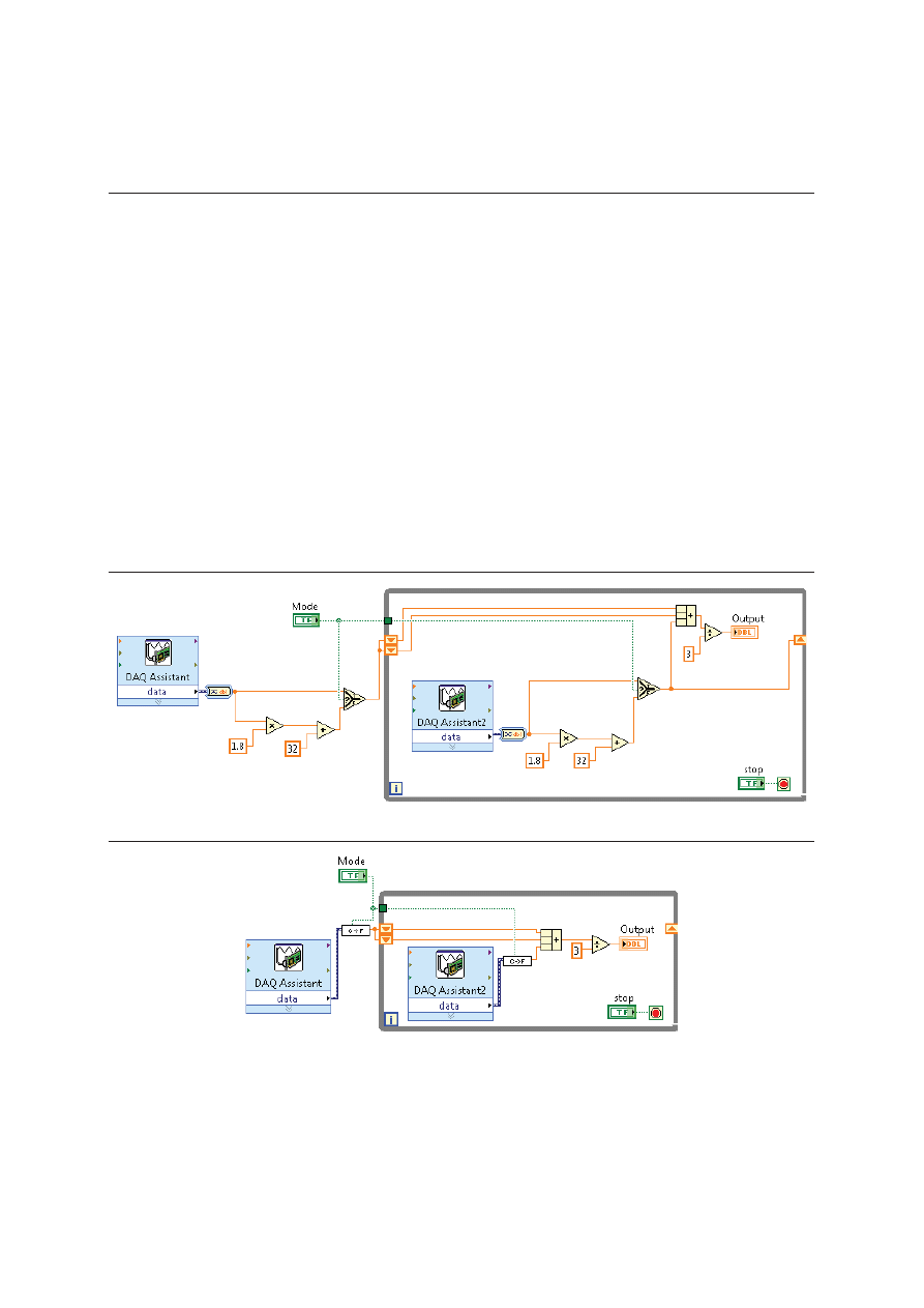
As you create VIs, you might find that you perform a certain operation frequently. Consider using
subVIs or loops to perform that operation repetitively. For example, the following block diagram
contains two identical operations.
Figure 4-1. Block Diagram with Two Identical Operations
Figure 4-2. Block Diagram with SubVIs for Identical Operations
The example calls the Temperature VI as a subVI twice on its block diagram and functions the
same as the previous block diagram. You also can reuse the subVI in other VIs.
LabVIEW Core 1 Course Manual
© National Instruments
| 4-3
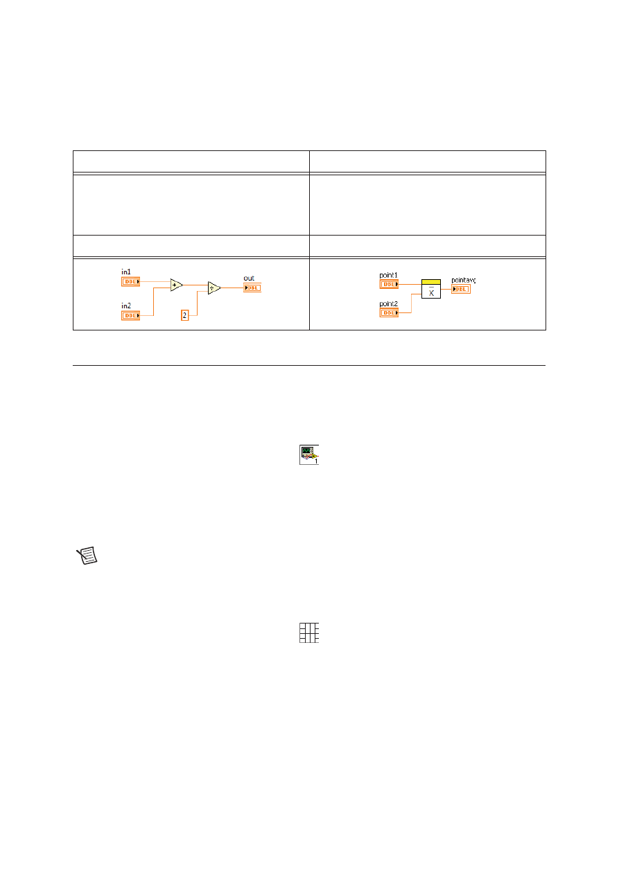
The following pseudo-code and block diagrams demonstrate the analogy between subVIs and
subroutines.
B. Building the Icon and Connector Pane
After you build a VI front panel and block diagram, build the icon and the connector pane so you
can use the VI as a subVI. The icon and connector pane correspond to the function prototype in
text-based programming languages. Every VI displays an icon in the upper right corner of the front
panel and block diagram windows.
A VI icon is a graphical representation of a VI. It can contain text, images, or a combination of
both. If you use a VI as a subVI, the icon identifies the subVI on the block diagram of the VI. If
you add the VI to a palette, the VI icon also appears on the Functions palette. You can double-click
the icon in the front panel window or block diagram window to customize or edit it.
Note
Customizing the icon is recommended, but optional. Using the default LabVIEW
icon does not affect functionality.
You also need to build a connector pane to use the VI as a subVI.
The connector pane is a set of terminals that correspond to the controls and indicators of that VI,
similar to the parameter list of a function call in text-based programming languages. The connector
pane defines the inputs and outputs you can wire to the VI so you can use it as a subVI. A connector
pane receives data at its input terminals and passes the data to the block diagram code through the
front panel controls and receives the results at its output terminals from the front panel indicators.
Function Code
Calling Program Code
function average (in1, in2, out)
{
out = (in1 + in2)/2.0;
}
main
{
average (point1, point2, pointavg)
}
SubVI Block Diagram
Calling VI Block Diagram

Lesson 4
Developing Modular Applications
4-4
| ni.com
Creating an Icon
Icons are graphical representations of VIs.
Every VI displays an icon in the upper right corner of the front panel and block diagram windows.
The default VI icon contains a number that indicates how many new VIs, up to nine VIs, you have
opened since launching LabVIEW. To disable this numbering, select Tools»Options»Front Panel
and remove the checkmark from the Use numbers in icons of new VIs (1 through 9) checkbox.
An icon can contain text or images. If you use a VI as a subVI, the icon identifies the subVI on the
block diagram of the VI. If you add the VI to a palette, the VI icon also appears on the Functions
palette.
Use the Icon Editor dialog box to edit a VI icon. Double-click the icon in the upper right corner
of the front panel or block diagram window to display the Icon Editor dialog box.
Create an icon to represent a VI or custom control graphically. Use the Icon Editor dialog box to
create or edit icons.
You can use banners to identify related VIs. National Instruments recommends creating and saving
a banner as a template. You then can use this template for a related VI icon and modify the body
of the VI icon to provide information about the specific VI.
Saving a Banner as a Template
Complete the following steps to save a banner as an icon template for a VI.
1. Double-click the icon in the upper right corner of the front panel window or block diagram
window, or right-click the icon and select Edit Icon from the shortcut menu, to display the Icon
Editor dialog box.
2. Press the <Ctrl-A> keys to select all user layers of the icon, and press the <Delete> key to delete
the selection. The default icon is a single user layer called VI Icon.
3. On the Templates page, select the
_blank.png
icon template from the VI»Frameworks
category. You can browse templates by category or by keyword.
4. Use the Fill tool on the right side of the Icon Editor dialog box to fill the banner of the icon
with a color.
5. Use the Text tool to enter text in the banner of the icon. While the text is active, you can move
the text by pressing the arrow keys.
6. Select File»Save As»Template to display the Save Icon As dialog box and save the icon as a
template for later use. LabVIEW saves icon templates as 256-color
.png
files.

LabVIEW Core 1 Course Manual
© National Instruments
| 4-5
Creating a VI Icon from a Template
Complete the following steps to create a VI icon that uses the template you created.
1. Press the <Ctrl-A> keys to select all user layers of the icon, and press the <Delete> key to delete
the selection.
2. On the Templates page, select the template you created. You can browse templates by category
or by keyword.
3. On the Icon Text page, enter up to four lines of icon text for the body of the icon. You can
configure the font, alignment, size, and color of the text. If you place a checkmark in the Center
text vertically checkbox, the Icon Editor dialog box centers the icon text vertically within the
body of the icon.
4. On the Glyphs page, drag and drop glyphs onto the Preview area.
Press the <F> key or the <R> key to flip a glyph horizontally or rotate a glyph clockwise,
respectively, as you move the glyph. You also can double-click a glyph to place the glyph in
the top-left corner of the icon. You can browse glyphs by category or by keyword.
5. Use the Move tool to move any glyph. Each glyph is on a separate layer and therefore moves
separately. Notice that the rest of the icon becomes dimmed when you select a glyph so you can
identify which selection you are moving.
6. Use the editing tools on the right side of the Icon Editor dialog box to edit the icon further if
necessary.
The Icon Editor dialog box creates a new user layer for each non-consecutive use of the editing
tools. Select Layers»Create New Layer to create a new user layer during consecutive uses of
the editing tools.
Note
You cannot modify the icon template or icon text with the editing tools on the
right side of the Icon Editor dialog box. Use the Templates page and the Icon Text page
to modify the icon template and icon text, respectively.
7. (Optional) Select Layers»Show Layers Page to display the Layers page. Use this page to
configure the name, opacity, visibility, and order of the layers of the icon.
8. Click the OK button to save the icon information with the VI and close the Icon Editor dialog
box.
You also can drag a graphic from anywhere in the file system and drop it in the upper right
corner of the front panel window to use the graphic as a VI icon. You can drag and drop
.png
,
.bmp
, or
.jpg
files.
Note
If you modify an icon by dragging and dropping a graphic from the file system,
LabVIEW creates a user layer called VI Icon for the graphic and deletes any other
existing icon information from the Icon Editor dialog box.
Lesson 4
Developing Modular Applications
4-6
| ni.com
Setting up the Connector Pane
Define connections by assigning a front panel control or indicator to each of the connector pane
terminals. The connector pane is located to the left of the VI icon in the upper right corner of the
front panel window. When you open LabVIEW, you see a default connector pattern.
Each rectangle on the connector pane represents a terminal. Use the rectangles to assign inputs and
outputs. The default connector pane pattern is 4 × 2 × 2 × 4. You can select a different pattern by
right-clicking the connector pane and selecting Patterns from the shortcut menu. If you anticipate
changes to the VI that would require a new input or output, keep the default connector pane pattern
to leave extra terminals unassigned.
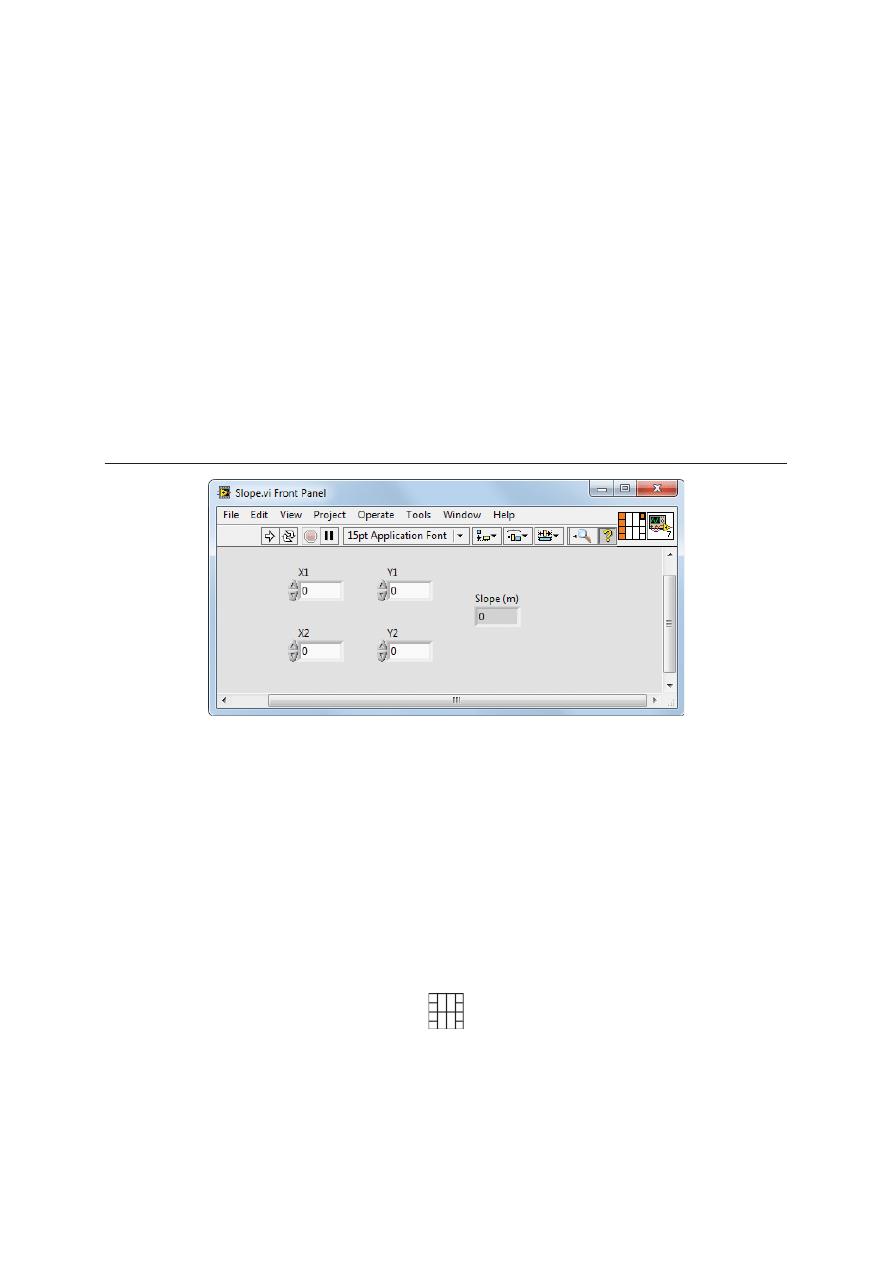
The front panel in Figure 4-3 has four controls and one indicator, so LabVIEW displays four input
terminals and one output terminal on the connector pane.
Figure 4-3. Slope VI Front Panel
Selecting and Modifying Terminal Patterns
Select a different terminal pattern for a VI by right-clicking the connector pane and selecting
Patterns from the shortcut menu. For example, you can select a connector pane pattern with extra
terminals. You can leave the extra terminals unconnected until you need them. This flexibility
enables you to make changes with minimal effect on the hierarchy of the VIs.
You also can have more front panel controls or indicators than terminals. You can assign up to 28
terminals to a connector pane.
The most commonly used pattern is shown below. This pattern is used as a standard to assist in
simplifying wiring.
LabVIEW Core 1 Course Manual
© National Instruments
| 4-7
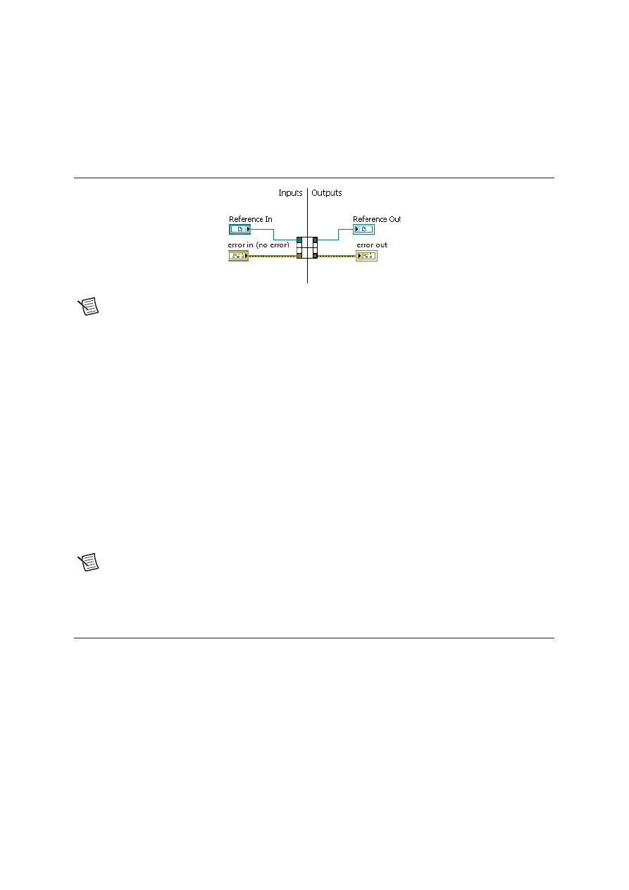
Figure 4-4 shows an example of the standard layout used for terminal patterns. The top inputs and
outputs are commonly used for passing references and the bottom inputs and outputs are used for
error handling.
Figure 4-4. Example Terminal Pattern Layout
Note
Avoid using connector panes with more than 16 terminals. Although connector
pane patterns with more terminals might seem useful, they are very difficult to wire.
If you need to pass more data, use clusters.
Assigning Terminals to Controls and Indicators
After you select a pattern to use for the connector pane, you can assign a front panel control or
indicator to each of the connector pane terminals. When you assign controls and indicators to the
connector pane, place inputs on the left and outputs on the right to prevent complicated or
confusing wiring patterns.
To assign a terminal to a front panel control or indicator, click a terminal of the connector pane,
then click the front panel control or indicator you want to assign to that terminal. Click an open
space on the front panel window. The terminal changes to the data type color of the control to
indicate that you connected the terminal.
You also can select the control or indicator first and then select the terminal.
Note
Although you use the Wiring tool to assign terminals on the connector pane to
front panel controls and indicators, no wires are drawn between the connector pane and
these controls and indicators.
C. Using SubVIs
To place a subVI on the block diagram, click the Select a VI button on the Functions palette.
Navigate to the VI you want to use as a subVI and double-click to place it on the block diagram.
You also can place an open VI on the block diagram of another open VI. Use the Positioning tool
to click the icon in the upper right corner of the front panel or block diagram of the VI you want to
use as a subVI and drag the icon to the block diagram of the other VI.

Lesson 4
Developing Modular Applications
4-8
| ni.com
Opening and Editing SubVIs
To display the front panel of a subVI from the calling VI, use the Operating or Positioning tool to
double-click the subVI on the block diagram. To display the block diagram of a subVI from the
calling VI, press the <Ctrl> key and use the Operating or Positioning tool to double-click the subVI
on the block diagram.
You can edit a subVI by using the Operating or Positioning tool to double-click the subVI on the
block diagram. When you save the subVI, the changes affect all calls to the subVI, not just the
current instance.
Setting Required, Recommended, and Optional Inputs and
Outputs
In the Context Help window, the labels of required terminals appear bold, recommended terminals
appear as plain text, and optional terminals appear dimmed. The labels of optional terminals do not
appear if you click the Hide Optional Terminals and Full Path button in the Context Help
window.
You can designate which inputs and outputs are required, recommended, and optional to prevent
users from forgetting to wire subVI terminals.
Right-click a terminal on the connector pane and select This Connection Is from the shortcut
menu. A checkmark indicates the terminal setting. Select Required, Recommended, or Optional.
You also can select Tools»Options»Front Panel and place a checkmark in the Connector pane
terminals default to required checkbox. This option sets terminals on the connector pane to
required instead of recommended. This applies to connections made using the wiring tool and to
subVIs created using Create SubVI.
Note
You can select Dynamic Dispatch Input (Required) or Dynamic Dispatch
Output (Recommended) for dynamic dispatch member VIs.
For terminal inputs, required means that the block diagram on which you placed the subVI will be
broken if you do not wire the required inputs. Required is not available for terminal outputs. For
terminal inputs and outputs, recommended or optional means that the block diagram on which you
placed the subVI can execute if you do not wire the recommended or optional terminals. If you do
not wire the terminals, the VI does not generate any warnings.
Inputs and outputs of VIs in
vi.lib
are already marked as Required, Recommended, or
Optional. LabVIEW sets inputs and outputs of VIs you create to Recommended by default. Set a
terminal setting to required only if the VI must have the input or output to run properly.
LabVIEW Core 1 Course Manual
© National Instruments
| 4-9
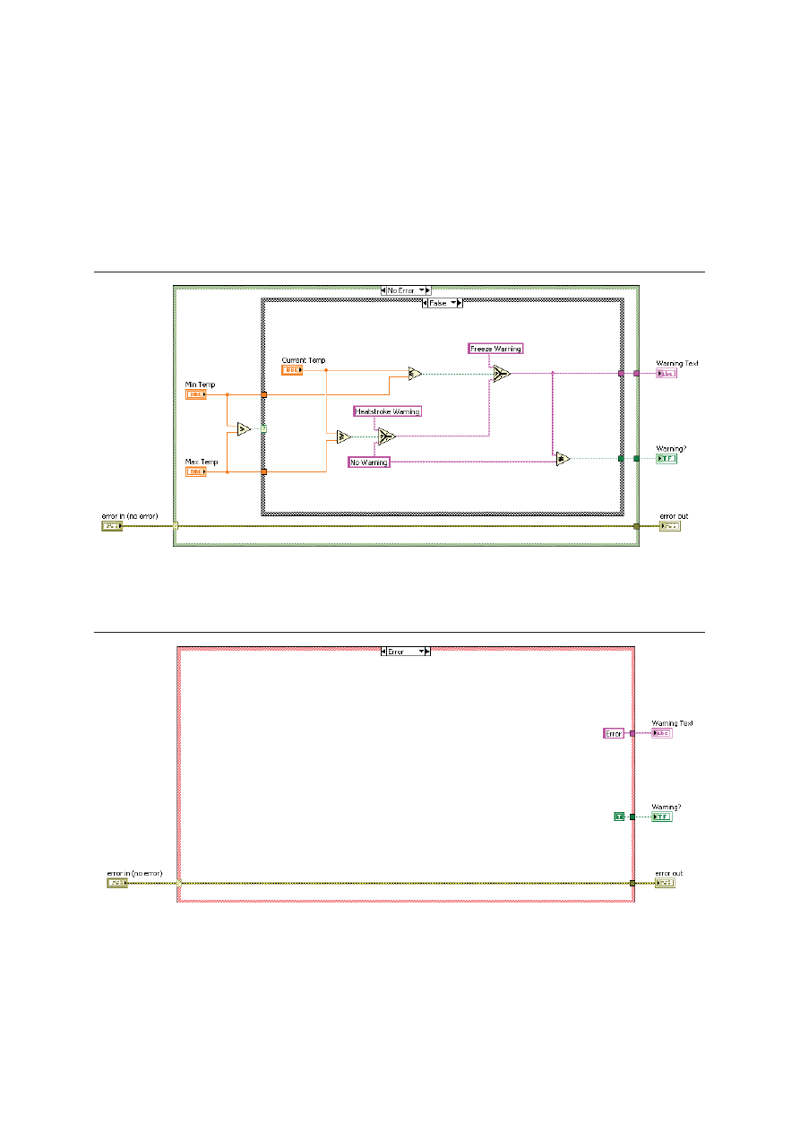
Handling Errors in SubVIs
You pass errors in and out of a subVI using error clusters. Using a Case structure, you handle errors
passed into the subVI with a No Error case and Error case.
The No Error case, as shown in Figure 4-5, contains the code for the normal operation of the subVI.
Figure 4-5. No Error Case of Sample SubVI
The Error case, as shown in Figure 4-6, typically passes the error from the error in cluster control
to the error out cluster indicator and contains any code necessary to handle the error.
Figure 4-6. Error Case of Sample SubVI
Lesson 4
Developing Modular Applications
4-10
| ni.com
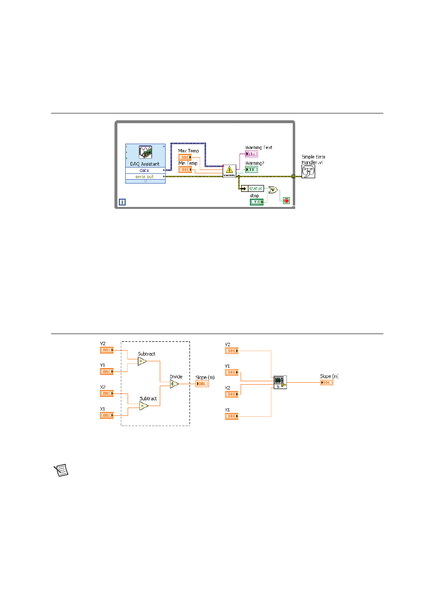
Avoid using the Simple Error Handler VI and General Error Handler VI inside subVIs. If
necessary, use these VIs in the calling VI, as shown in Figure 4-7.
Figure 4-7. Block Diagram of Calling VI
Creating a SubVI from an Existing VI
You can simplify the block diagram of a VI by converting sections of the block diagram into
subVIs. Convert a section of a VI into a subVI by using the Positioning tool to select the section of
the block diagram you want to reuse and selecting Edit»Create SubVI. An icon for the new subVI
replaces the selected section of the block diagram. LabVIEW creates controls and indicators for
the new subVI, automatically configures the connector pane based on the number of control and
indicator terminals you selected, and wires the subVI to the existing wires.
Figure 4-8 shows how to convert a selection into a subVI.
Figure 4-8. Creating a New SubVI
The new subVI uses a default pattern for the connector pane and a default icon. Double-click the
subVI to edit the connector pane and icon, and to save the subVI.
Note
Do not select more than 28 objects to create a subVI because 28 is the maximum
number of connections on a connector pane. If your front panel contains more than
28 controls and indicators that you want to use programmatically, group some of them
into a cluster and assign the cluster to a terminal on the connector pane.
Wyszukiwarka
Podobne podstrony:
Cw 6 Tworzenie aplikacji modułowych Zadania domowe
Cw 6 Tworzenie aplikacji modułowych Instrukcja
Cw 6 Tworzenie aplikacji modułowych Zadania domowe
Cw 6 Tworzenie aplikacji modułowych Instrukcja
Cw 3 Wyszukiwanie błędów w VI Materiały dodatkowe
materiały dodatkowe sedymentologia ćw II0001
Cw 5 Struktury Danych Materiały dodatkowe
Cw 4 Implementacja VI Materiały dodatkowe
Tworzenie się wzorców ruchowych - referat, STUDIA - Kierunek Transport, STOPIEŃ I, MATERIAŁY DODATKO
materiały dodatkowe cw 3 i 4a
Cw 2 Nawigacja w LabVIEW Materiały dodatkowe
Materialy dodatkowe cw 3 i 4 id Nieznany
Cw 7 Obsługa zdarzeń Materiały dodatkowe
materiały dodatkowe sedymentologia ćw II0001
Cw 5 Struktury Danych Materiały dodatkowe
więcej podobnych podstron