Appendix 7: Choosing Pipe in a Closed Diversion System
Once you have determined the water source inlet and measured the static head (vertical
change in elevation) from the water source inlet to the turbine, measure the lineal distance
for the path that the pipe for the diversion system will follow. You now want to select the
optimal pipe diameter for your diversion system. The larger the pipe diameter, the less the
friction loss will be. However, larger diameter pipes also cost more. You need to meet the
hydro turbine’s dynamic pressure and flow volume requirements. Beyond that, the optimal
pipe diameter is the one that gives you the best cost-benefit ratio – the least cost per PSI of
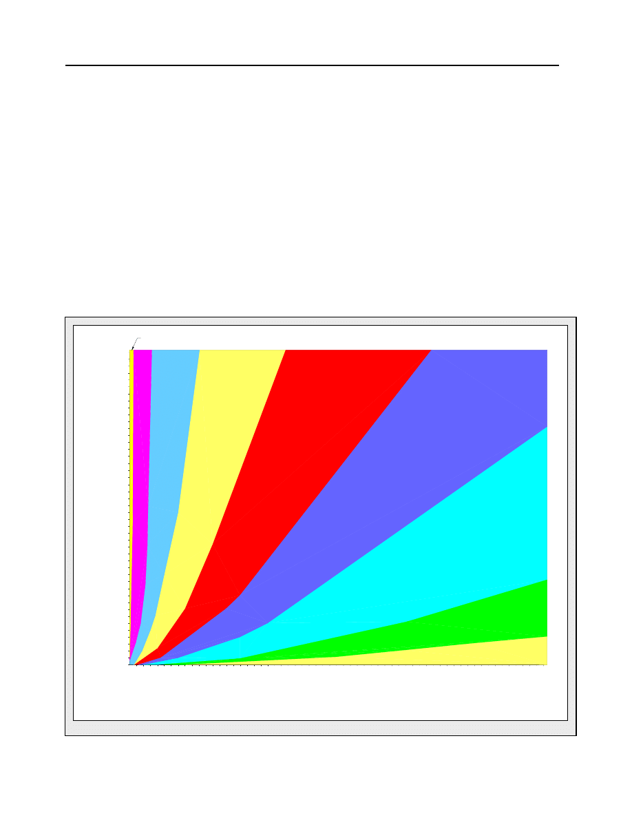
dynamic pressure. In the graph below we have provided a simple means of determining
which pipe diameter to use, based on static head and flow information.
This graph is based on the assumption that your pipeline will have no turns or fittings with a
radius greater than 22 degrees, and that it’s overall length is under 500ft. If you do have
additional friction losses from these elements, you will need to size your pipeline larger than
what we have recommended here. In this case, we strongly recommend you contact our
engineering staff to help you in designing and planning your system. Keep in mind that your
flow must be adequate to keep the pipeline full even at low water levels to maintain a closed
system and prevent cavitation and turbulence caused by air drawn into the system intake.
5
10
15
20
30
60
50
40
70
80
90
150
125
175
200
225
50
100
150
200
250
300
350
400
450
500
550
600
650
700
750
800
850
900
950
1000
11
00
1200
1300
1400
1500
H
ead
(f
ee
t)
Flow (Gallons/minute)
4in pipe
We recommend
5in diameter pipe
3i
n
pi
pe
2i
n
pi
pe
1in pipe
We recommend
8in diameter pipe
10in pipe
use a diversion channel
We recommend
6in diameter pipe
Appendix 8: Other Pipeline Friction Losses
Another major cause of head loss is in any fittings you might use. Avoid sharp
corners in planning your pipeline, because sharp corners will cause turbulence and
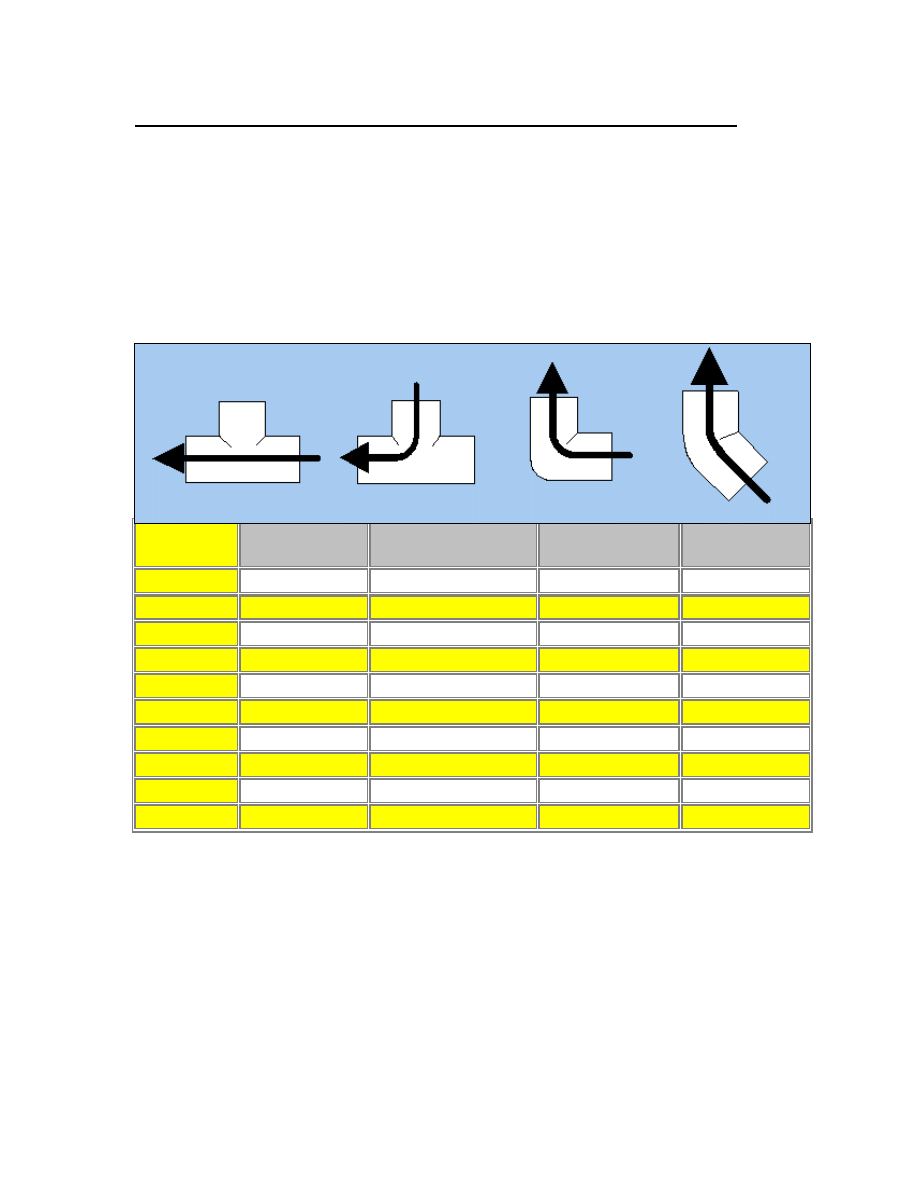
hence increase friction. The table below lists friction losses associated with various
common plumbing fittings. It shows how many feet of pipeline length the fitting is
equivalent to, in terms of friction loss. For example: A ‘T’ in a 4-inch pipeline
represents 22ft of head lost – OUCH! Your goal in planning your pipeline is to keep
it as straight as possible. Bends and curves should be less than 22 degrees. This is
best accomplished with smooth, flexible hose sections making gradual curves where
necessary, or by carefully heating and bending straight pipe sections to your needs.
Pipe
Diameter
Tee-Run
Tee-Branch
90° Ell
45° Ell
½
1.0 feet
4.0 feet
1.5 feet
0.8 feet
¾
1.4 feet
5.0 feet
2.0 feet
1.0 feet
1
1.7 feet
6.0 feet
2.3 feet
1.4 feet
1¼
2.3 feet
7.0 feet
4.0 feet
1.8 feet
1½
2.7 feet
8.0 feet
4.0 feet
2.0 feet
2
4.3 feet
12.0 feet
6.0 feet
2.5 feet
2½
5.1 feet
15.0 feet
8.0 feet
3.0 feet
3
6.3 feet
16.0 feet
8.0 feet
4.0 feet
3½
7.3 feet
19.0 feet
10.0 feet
4.5 feet
4
8.3 feet
22.0 feet
12.0 feet
5.0 feet
Some other sources of potential head loss to be aware of:
· Trash-rack/screen – clogged or poorly designed
· Pipe inlet – clogged inlet or inlet not properly submerged
· Valves – use gate, butterfly, or ball valves only in hydro systems as they
allow unobstructed flow when open
· Size transitions in pipeline diameter, both increase or decrease
· Poorly sealed joints which allow air to be sucked into the pipeline
Wyszukiwarka
Podobne podstrony:
pipe expansion id 121780 Nieznany
Pipe Box
PiPE
pytania pipe 11
Pipe Dimensions Weights Chart
Pass the Peace Pipe
Plastic Pipe
pipe
2002 04 19 Pipe Exp[1]
Copper Pipe
Pipe Clamp Blocks
SABIC Pipe backgrounder Polish, Materiały studia, materiały polimerowe
pipe expansion id 121780 Nieznany
Copper Pipe
więcej podobnych podstron