6 December, 2001
g.hall@ic.ac.uk
www.hep.ph.ic.ac.uk/~hallg/
1
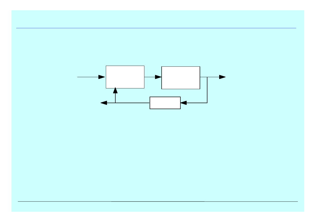
Phase Locked Loops - PLL
•frequency selective feedback system
wide use in FM detectors, stereo demodulators, tone decoders, frequency
synthesisers, frequency synchronisation,…
•Voltage Controlled Oscillator
in feedback loop
reference oscillation, with frequency dependent on DC voltage
•Phase detector
compares periodic input signal with output of VCO and adjusts in response
•Low pass filter
generates correction voltage from phase detector output
Phase
detector
Low pass
filter
Low pass
filter
Low pass
filter
VCO
Voltage
out
Frequency
out
Signal
input
6 December, 2001
g.hall@ic.ac.uk
www.hep.ph.ic.ac.uk/~hallg/
2
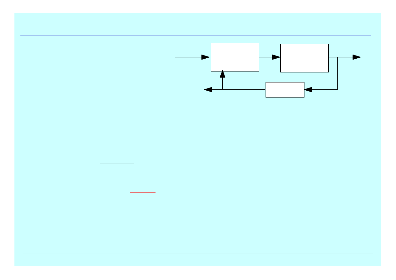
PLL operation
•No signal present
error voltage = 0
VCO "free runs" at f
0
•Apply periodic signal at f
s
f
s
≈
f
0
phase comparison with VCO generates error voltage...
...which forces VCO to synchronise with f
s
PLL "locks" onto input frequency
VCO frequency identical to input frequency, but with phase difference
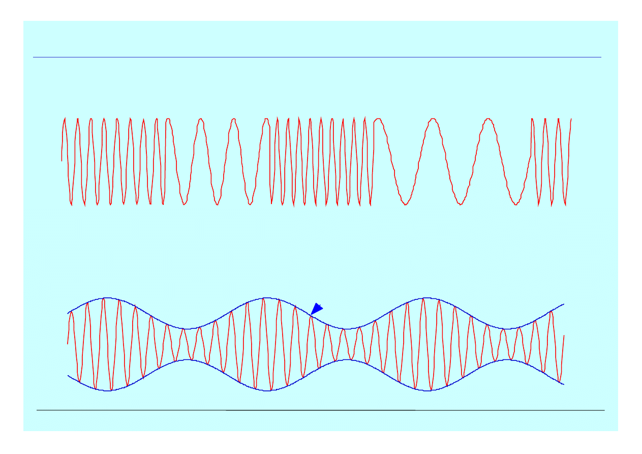
•If input frequency varies slowly, PLL will remain locked
will track input frequency
eg input clock with jitter (phase noise), PLL will "clean up" clock
FM radio: audio signal much lower frequency than carrier
voltage output will follow audio
Phase
detector
Low pass
filter
Low pass
filter
Low pass
filter
VCO
Voltage
out
Frequency
out
Signal
input
6 December, 2001
g.hall@ic.ac.uk
www.hep.ph.ic.ac.uk/~hallg/
3
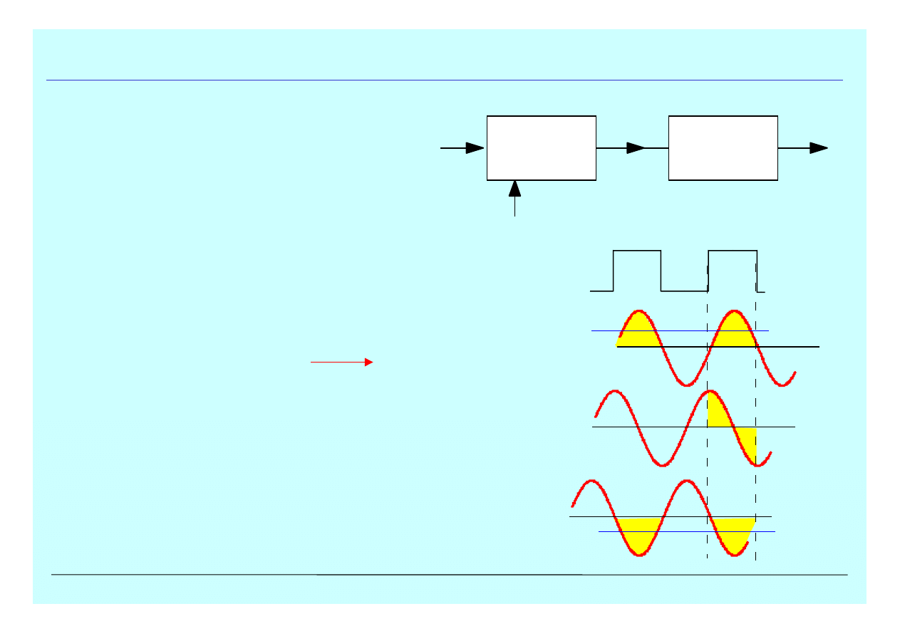
Phase sensitive detection
•Mix input and reference signals
V ~ sin
ω
0
t.sin
ω
s
t
produces two components
f ~ 2f
0
f =
∆
f ie low frequency
•pass though low pass filter
τ
>> 1/f
produces error voltage
•actual method different
V
error
= Acos
φ
cos
φ
dependence not ideal for
real applications
Phase
detector
Low pass
filter
Low pass
filter
f
s
f
o
f
o
+f
s
f
o
-f
s
0
V
S
∆ φ
=0
∆ φ
=
π
/2
∆ φ
=
π
error voltage > 0
error voltage = 0
error voltage < 0
VCO output
6 December, 2001
g.hall@ic.ac.uk
www.hep.ph.ic.ac.uk/~hallg/
4
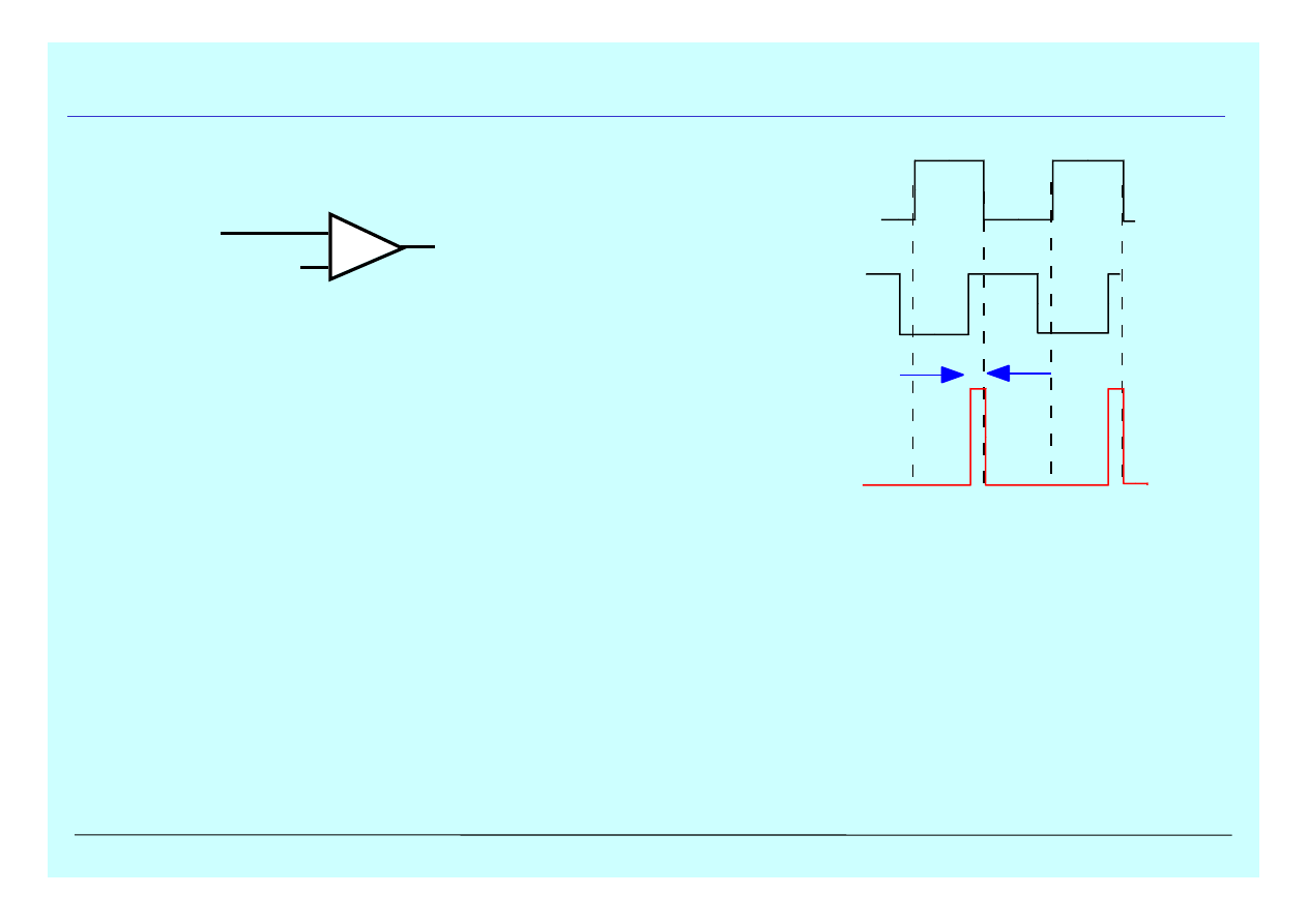
Improved phase detector
•Transform sine wave to square wave
V
ref
= (v
max
- v
min
)/2
or input may already be pulsed
VCO output
signal after
comparator
product
0
V
S
∆ φ
+
-
vout
v
Vref
6 December, 2001
g.hall@ic.ac.uk
www.hep.ph.ic.ac.uk/~hallg/
5
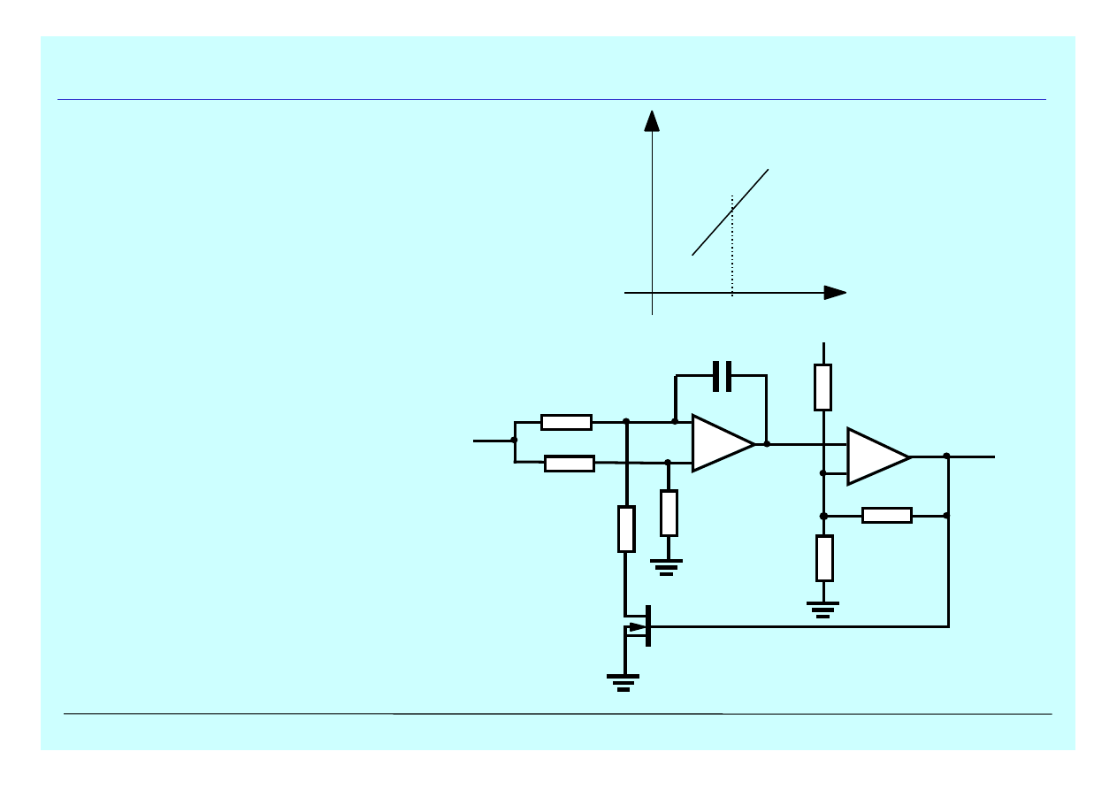
Voltage Controlled Oscillator VCO
-
+
R1
R1
R1
R
2R
+
-
vout
R
+VS
V
in
R
C
•ideal VCO behaviour
•moderate frequency example
nMOS = switch
f
V
f
0

6 December, 2001
g.hall@ic.ac.uk
www.hep.ph.ic.ac.uk/~hallg/
6
PLL operation
•For phase locking, require f
s
≈
f
0
=> sensitive to finite range of frequencies
•Capture range
frequency range over which PLL can lock on signal
•Lock range
frequency range over which PLL can track input variation
•Role of low pass filter - decreasing bandwidth (increasing
τ
)
slows capture process, increases time to lock
decreases capture range
once locked, greater immunity to high frequency interference
transient response to sudden changes in frequency within capture range becomes
underdamped
6 December, 2001
g.hall@ic.ac.uk
www.hep.ph.ic.ac.uk/~hallg/
7
PLL applications (i)
•FM demodulation
PLL tracks variation in frequency
also used in Frequency-shift keying - where mark/space ratio changes, not f
•AM detection
if input is sinusoidal, then PLL can demodulate signal from carrier
carrier wave
signal wave
6 December, 2001
g.hall@ic.ac.uk
www.hep.ph.ic.ac.uk/~hallg/
8
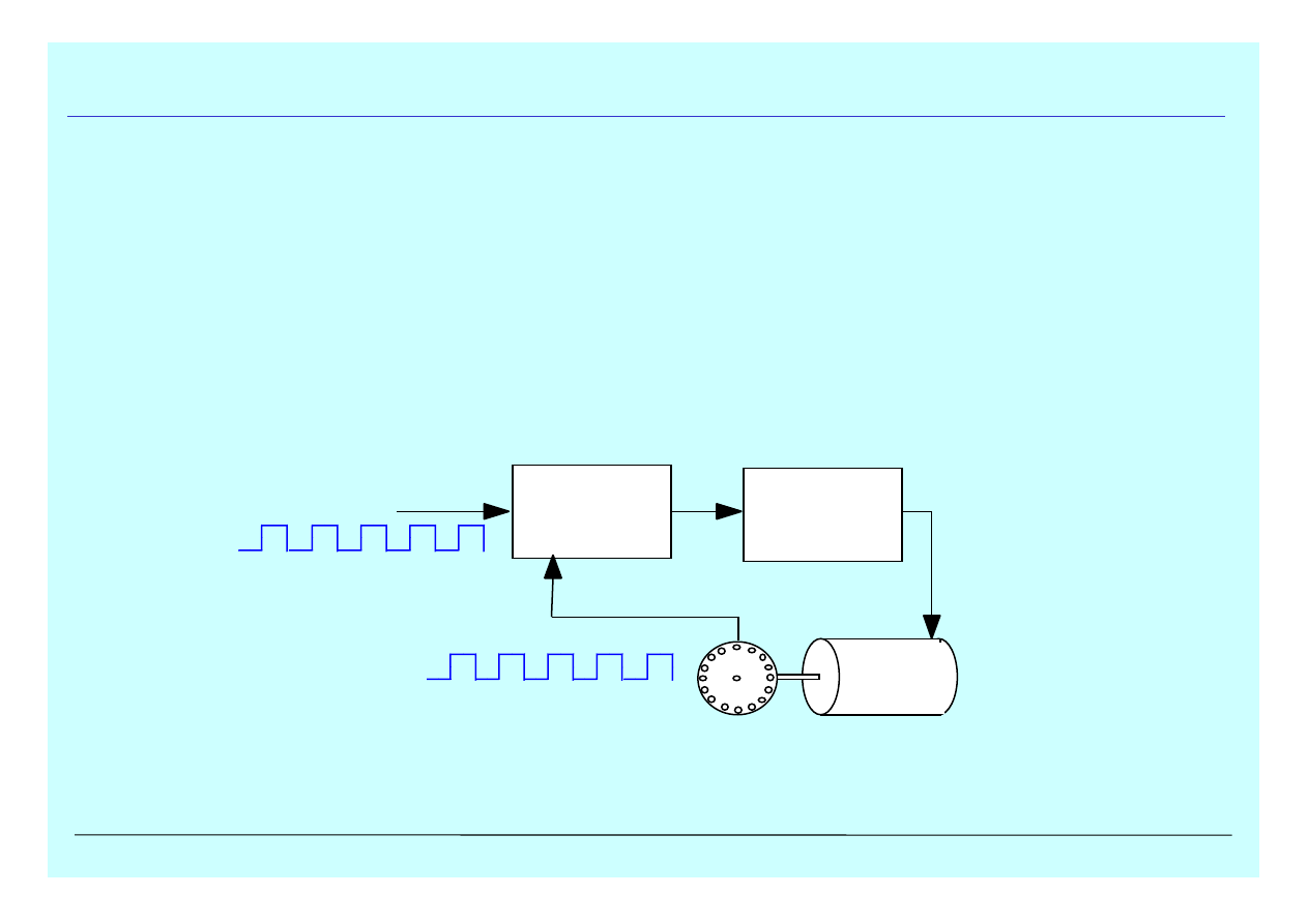
•Frequency synchronisation and signal conditioning
a poor oscillator can be locked to good reference signal - eg colour TV
remove out-of-range interference, ie phase jitter
•Synchronisation for control
eg motor speed - required for many applications
eg CD player
PLL applications (ii)
Phase
detector
Low pass
filter
Low pass
filter
Low pass
filter
error
voltage
encoder
reference
frequency
motor
feedback
frequency

6 December, 2001
g.hall@ic.ac.uk
www.hep.ph.ic.ac.uk/~hallg/
9
•Frequency synthesis
multiply reference frequency by N, by dividing output in feedback loop
•Frequency translation
by adjusting response to out of phase signal at input, can offset by small
∆
f
•Tone or carrier detection
simply detect if a given frequency is present with magnitude above threshold
useful eg in stereo decoders, modem
PLL applications (iii)
Wyszukiwarka
Podobne podstrony:
kompozytorklasowek gwo pl application pdfQuestions y=1339356508
Applications and opportunities for ultrasound assisted extraction in the food industry — A review
Lab12 Applications
Baxter Vaccine Patent Application
Applications of polyphase filters for bandpass sigma delta analog to digital conversion
Magnetic Treatment of Water and its application to agriculture
2 Application of Distributed Loads
2004 Applications of RT to translation
61 881 892 Evaluation of PVD Coatings for Industrial Applications
Consular Electronic Application Center Print Application
Cerwin Vega Stealth 8 application
application of solid state fermentation to food industry a review
Electron ionization time of flight mass spectrometry historical review and current applications
[2006] Application of Magnetic Energy Recovery Switch (MERS) to Improve Output Power of Wind Turbine
Formal Letter letter of application (course)
Zied H A A modular IGBT converter system for high frequency induction heating applications
applicationsofal00broorich bw
Mechanical Pumps Centrifugal Pumps Design & Application
l200 application note
więcej podobnych podstron