
1
Part I
Getting Started
with AutoCAD
®
Mechanical 6
Part I provides information for getting started with your AutoCAD Mechanical 6 software.
It includes an overview of the product capabilities and functionality, and information
about the migration of files from previous releases.
In addition, Part I provides a guide to both the print and online documentation that you
received with your AutoCAD Mechanical software. Information about training courseware
and Internet resources are also included.

2
|

3
In This Chapter
1
Where to Start
This chapter provides information to get you started
using the AutoCAD
®
Mechanical 6 software. It describes
the basic concepts for modeling with the software, and
the migration of files from previous releases.
An overview of the printed and online documentation
is included, along with resources for product learning,
training, and support. Read this section so that any time
you need product information, you will know where to
locate it.
■
The AutoCAD Mechanical 6
software package
■
Modeling concepts
■
Where to go first
■
Migration Assistance
■
AutoCAD Mechanical Today
■
Product documentation
■
Internet resources
■
Typographical conventions

4
|
Chapter 1
Where to Start
About AutoCAD Mechanical
AutoCAD Mechanical is a 2D mechanical design solution built for designers
and detailers who require high-quality drafted output with minimal effort.
Built on the AutoCAD 2002 software platform, the AutoCAD Mechanical 6
design software package includes:
■
AutoCAD Mechanical 6 with the power pack (2D Parts and Calculations)
■
AutoCAD 2002
The AutoCAD Mechanical software provides 2D mechanical engineering and
design tools, including:
■
Improved design and detailing tools, including cams, springs, holes, and
notes for holes and standard parts.
■
Improved workflow and compliance with company standards.
■
Intelligent production drawing and detailing.
■
Assembly tools for managing detailed 2D drawings and assemblies.
■
Standards based design and content, with more than half a million
reusable 2D standard parts, features, holes and structural steel shapes.
■
Machinery systems generators that speed up systems creation and reduce
errors.
■
Engineering calculations that provide greater accuracy.
■
Collaboration tools, including support for Autodesk Streamline.
■
Built-in IGES translator.
Modeling with AutoCAD Mechanical 6
AutoCAD Mechanical 6 software contains over half a million standard parts
with data that can be quickly incorporated into any design. These include
common parts such as predrawn screws, nuts, washers, pins, rivets, bushings,
rings, seals, bearings, and keys. AutoCAD Mechanical also includes 8000
predrawn standard features including center holes, undercuts, keyways, and
thread ends.
Object Oriented Construction
AutoCAD Mechanical 6 extends drawing objects to include contours,
centerlines, symbols, shafts, screws, and bearings. It is not necessary to
manually change individual elements of drawing objects in AutoCAD
Mechanical 6.
Modeling with AutoCAD Mechanical 6
|
5
AutoCAD Mechanical 6 automatically changes all the elements of an object
when an edit occurs. For example, if the nominal diameter of a screw
connection is changed, all elements of the screw connection (such as edges
and hatches) are recognized and changed automatically.
The use of intelligent objects in AutoCAD Mechanical 6, such as screw
connections, is an object-oriented approach to construction. This approach
makes it faster and easier to create mechanical designs, provides large
productivity gains during changes, and reduces the chance of costly errors.
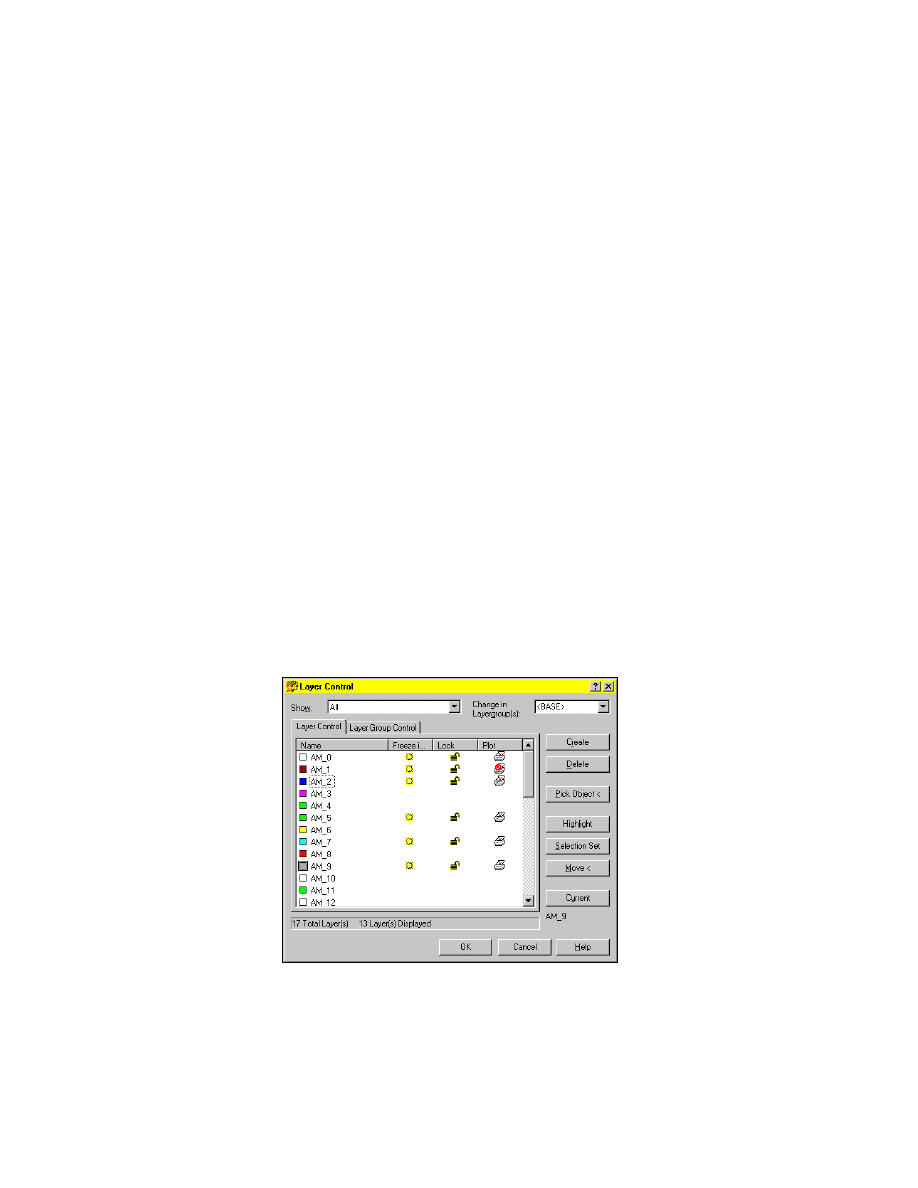
Layer and Layer Groups
The layer system in AutoAD Mechanical is made up of working layers,
standard parts layers, and special layers. All layers perform specific tasks and
are recognized by AutoCAD Mechanical commands. For instance, contour
lines, construction lines, centerlines, dimension lines, and corss-hatching
lines are placed on separate layers. AutoCAD Mechanical creates layers in the
drawing when they are needed and allocates the object to the appropriate
layer.
■
Working Layers consist of the base layers and standard part layers. Working
layers are repeated in each layer group.
■
Special Layers are used for drawing borders, part references, construction
lines, and viewports. Special layers are created once for the whole drawing.
Special layers make a drawing more clear and speed up plotting.
■
Layer Groups are used to organize associated or related elements to a
drawing. A working layer and standard parts layer is created for every layer
group. You can create any number of layer groups.

6
|
Chapter 1
Where to Start
Linetypes, Lineweight, and Color
The attributes of lineweights, linetypes and colors in predefined layers are
defined by the standard set in the drawing configuration.
The AutoCAD Mechanical layer management system automatically
configures almost all drawing elements. Since the object attributes of almost
all drawing elements are configured with the ByLayer method, centerlines,
construction lines, hidden edges, and so on, are controlled automatically.
Dimension Styles
AutoCAD Mechanical 6 contains several dimension styles, which are applied
automatically depending on the function using the dimension style feature,
and the current standard selected.
Text Styles and Text Fonts
There are four text style formats available which have different text heights,
and alignments. AutoCAD Mechanical 6 offers font databases with a vast
number of special characters, such as the diameter symbol.
Scale Factors
The scale of dimensions, symbols, or hatches vary depending on the base scale
factor, the scale of the drawing border, or the scale area that is set in the drawing.
The base scale factor can be set in the Mechanical Options dialog box, or by
inserting a predefined drawing border for a new drawing. If you combine
several drawing borders to a file, each of the drawings can have a different
plot scale.
In model space it is easy to create multiple scale areas with different scale
factors. Each scale area controls the scale of text, dimensions, and symbol
properties regardless of the base scale factor of the drawing.
You can create viewports and assign layout attributes including scale factor
from the layout tab. It is also possible to create new viewports based on
existing scale areas in model space.
Rescaling Objects
If you determine that the format or the scale factor for a drawing border has
to be changed, AutoCAD Mechanical 6 rescales all affected drawing objects.
All texts, dimensions, and symbols, are automatically resized according to
the new scale factor.

Starting AutoCAD Mechanical
|
7
Starting AutoCAD Mechanical
You can start AutoCAD Mechanical by using one of the following procedures:
■
Click Start on the task bar, and then choose Programs. Select AutoCAD
Mechanical 6 or AutoCAD Mechanical 6 Power Pack.
■
On the desktop double-click an AutoCAD Mechanical icon:
Where to Go First
The information in this section helps you locate the documentation that is
most helpful for your level of experience.
See “Printed and Online Manuals” on page 11 for a description of the printed
and online documentation components and their locations.
New AutoCAD User
If you are new to AutoCAD 2002:
■
See the AutoCAD 2002 User's Guide, which explains concepts and provides
procedures for completing common drafting tasks. The glossary helps you
understand AutoCAD 2002 terminology.
■
Quick Reference Card: An at-a-glance reference to AutoCAD toolbars and
accelerator keys. The card is located at the back of the printed User’s Guide,
but is not available online.
Once you are familiar with AutoCAD 2002, follow the suggestions in the next
section for learning AutoCAD Mechanical 6.
New AutoCAD Mechanical 6 User
If you are familiar with AutoCAD, but you are new to AutoCAD Mechanical:
■
Read chapter 2, “Features and Commands” on page 17. This is an
overview of AutoCAD Mechanical basics and the user interface.
■
Complete the AutoCAD Mechanical tutorials in this manual. The tutorials
are also offered in PDF format on the product CD and on the Web.
■
Refer to the Glossary in the Help to familiarize yourself with AutoCAD
Mechanical terminology.
■
Choose AutoCAD Mechanical on the Help menu for information about
commands, procedures, and concepts. The Help in AutoCAD Mechanical
is specific to AutoCAD Mechanical with the power pack.
8
|
Chapter 1
Where to Start
Upgrading User
If you are upgrading from a previous release of AutoCAD Mechanical, see
chapter 3, “New and Revised Commands” on page 37 for all of the revised
and new features in this release.
Compatibility
If you are saving a file in AutoCAD Mechanical 6 format, the drawing is not
compatible with drawings saved in AutoCAD Mechanical 2000i format.
However, it is possible to save AutoCAD Mechanical 6 files in AutoCAD
Mechanical 2000i format with the revised Save As command.
Accessing AutoCAD Mechanical Commands
AutoCAD Mechanical provides several methods to access commands and
manage your design process.
The following are samples of the access methods available to you:
Context Menu
In the graphics area, right-click and choose Power Edit.
Toolbutton
Power Edit
Desktop Menu
Modify ➤ Power Commands➤ Power Edit
Command
AMPOWEREDIT
The step-by-step procedures in the tutorials indicate the command name in
the opening procedural text. The appropriate toolbutton is displayed in the
margin next to the preferred access method. In the tutorials, the context
menu method is used when the menus are sensitive to what you are doing.
The Browser method is used when you can save time and steps. You can use
any of the alternate methods as well.
Here is an example of how methods are used in the tutorials:
1
Use
AMPOWEREDIT
to edit a feature.
Context Menu
In the graphics area, right-click and choose Power Edit.
NOTE
To find the location of a particular toolbutton, refer to Appendix A.

Migration Assistance
|
9
Migration Assistance
The Migration Assistance in AutoCAD Mechanical 6 helps to migrate Genius
14 parts lists, layers, and symbols to use with AutoCAD Mechanical 6.
The File Migration Tool (FMT) is a component of AutoCAD Mechanical 6
Migration Assistance, an independent Visual Basic (not VBA) application
located on your product CD. The FMT migrates multiple files from previous
releases of AutoCAD Mechanical to the current format. You can install
AutoCAD Mechanical 6 Migration Assistance during or after the installation
of your Autodesk mechanical product.
To install the Migration Assistance from your product CD
1
Hold down the
SHIFT
key while you insert the product CD into the CD-ROM
drive. This prevents Setup from starting automatically.
2
In the file tree of the CD-ROM drive, navigate to the Migrate folder and
double-click setup.exe.
3
Respond to the directions in the AutoCAD Mechanical 6 Migration
Assistance installation dialog boxes.
For more information about the Migration Assistance, refer to the AutoCAD
Mechanical 6 and Mechanical Desktop 6 Installation Guide on your product CD.

10
|
Chapter 1
Where to Start
AutoCAD Mechanical Today
The first time you open the AutoCAD Mechanical program, the Today
window is displayed on top of the program interface along with instructions
about how to use it. The Today feature is a powerful tool that makes it easy
to manage drawings, communicate to design teams, and link directly to
design information.
In the Today window, you can expand the following options for access to the
services you require.
My Workplace
Connect directly to files on your computer and your local
network.
My Drawings
Open existing drawings, create new ones, or access
symbol libraries.
Bulletin
Board
Post your own Web page with links to block libraries, CAD
standards, or other folders and directories on your
company intranet. CAD managers can use the Bulletin
Board to communicate with their design teams. An HTML
bulletin board template is provided.
The Web
Connect directly to the Internet.
Autodesk
Point A
Link directly to design information and tools such as
www.Buzzsaw.com on the Web. Use the units converter,
link to Autodesk Web sites, and much more.
Login and create your free account. Customize the
information in Autodesk Point A for your specific needs.
You can close the Today Window and use the File menu to create new
drawings or open existing drawings.
If you prefer not to see the Today Window when you start AutoCAD Mechanical,
you can turn it off in Assist ➤ AutoCAD Options ➤ System ➤ Startup.

Printed and Online Manuals
|
11
Printed and Online Manuals
The documentation provided with your purchase of AutoCAD Mechanical 6
software includes:
■
AutoCAD Mechanical 6 User’s Guide in print and on the product CD-ROM
■
AutoCAD User’s Guide in HTML format in the AutoCAD
product Help.
■
AutoCAD Mechanical 6 and Mechanical Desktop 6 Installation Guide in PDF
format on the product CD.
The AutoCAD Mechanical 6 manuals are also available in PDF format on the
AutoCAD Mechanical Web page at http://www.autodesk.com/autocadmech ➤
Product Information ➤ Documentation.
AutoCAD Mechanical Printed Manual
The printed AutoCAD Mechanical 6 User’s Guide is divided into two parts.
Part I
An introduction to the product and information you need
to get started using the software.
Part II
A set of tutorials to expand your skills in using AutoCAD
Mechanical.
What’s New In the Tutorials
This release of AutoCAD Mechanical 6 has many features that will help you
create drawings faster and more intuitively. In addition, you will find:
■
New toolbuttons providing access to more commands
■
Shortcut menus, accessible in the graphics area as you work on your
drawing.
■
Redesigned command prompts and user interfaces that provide more
information, and make it easier to choose from command options.
Use the following chapter descriptions as a guide to new features.
Chapter 4
Working with Templates: Improved Mechanical Options
dialog box and AutoCAD Mechanical Today window.
Chapter 5
Working with Layers and Layer Groups: New Visibility
Enhancement dialog box.
Chapter 6
Designing Levers: New Power Dimensioning dialog box.
Chapter 7
Working with Model Space and Layouts: Improved Detail
dialog box.

12
|
Chapter 1
Where to Start
Chapter 8
Dimensioning: Improved Power Dimensioning dialog
box.
Chapter 9
Working with 2D Hide and 2D Steel Shapes: new 2D Hide
feature, and insert and modify steel shapes.
Chapter 10
Working with Standard Parts: screw assembly templates.
Chapter 11
Working with a Bill of Material and a Parts List: improved
part reference behavior
Chapter 12
Creating Shafts with Standard Parts: start a new drawing
and use a predefined template with AutoCAD Today.
Chapter 13
Calculating Shafts: improved shaft calculation routine
and new strength calculation routine.
Chapter 14
Calculating Moments of Inertia and Deflection Lines:
improved material selection dialog
Chapter 15
Calculating Chains: improved methods to create and
calculate chains or belts.
Chapter 16
Calculating Springs: improved spring calculation routine.
Chapter 17
Calculating Screw Connections: new screw calculation
routine.
Chapter 18
Calculating Stress Using FEA: improved command line
prompts for the FEA routine.
Chapter 19
Designing and Calculating Cams: improved cam design
and calculation routine.
AutoCAD Printed Manual
The AutoCAD User’s Guide contains comprehensive information and
instructions for using AutoCAD. This manual is available in HTML format in
the AutoCAD Help, and in PDF format on the product CD.
Online Installation Guide
The AutoCAD Mechanical 6 and Mechanical Desktop 6 Installation Guide is
available on the product CD. It provides the following information:
Introduction
What’s in the software.
Chapter 1
System requirements and recommendations for installing
and running the software.

Printed and Online Manuals
|
13
Chapter 2
Procedures to install, upgrade, authorize, and maintain
the software for a single user, and information you need
to know before you begin your installation.
Chapter 3
Information for network administrators. Instructions for
installing and configuring for a network environment.
Chapter 4
Technical information about environment variables and
performance enhancements to optimize performance of
the software.
Chapter 5
Information about cabling and option settings, plus other
information necessary to link and configure plotters and
printers with AutoCAD Mechanical/Mechanical Desktop.
Chapter 6
Instructions to uninstall the software, maintain your hard
disk, and recover data in case of a system failure.
AutoCAD 2002 Documentation
You should be familiar with AutoCAD before you use AutoCAD Mechanical.
The complete set of AutoCAD 2002 documentation is available in the
AutoCAD Help. It includes:
■
User's Guide*
■
Command Reference*
■
Customization Guide*
■
ActiveX
®
and VBA Developer's Guide*
■
ActiveX
®
and VBA Reference
■
AutoLISP
®
Reference
■
Visual LISP
TM
Developer's Guide*
■
Visual LISP
TM
Tutorial*
■
DXF
TM
Reference
■
Driver Peripheral Guide
■
Connectivity Automation Reference
■
Network Administrator’s Guide
AutoCAD 2002 manuals marked with an asterisk can be ordered in print from
your local reseller.
If you currently own a valid license for an Autodesk product and require
replacement media or documentation, please call the Customer Service
Center at 1-800-538-6401 to order.

14
|
Chapter 1
Where to Start
AutoCAD Mechanical Help
The Help in AutoCAD Mechanical provides information about AutoCAD
Mechanical with the power pack.
The Help is formatted for easy navigation, and includes:
■
Content organized by the major functional areas of AutoCAD Mechanical,
with How To, Reference, and Learn About pages for each functional area
■
Specific information about each of the features in the program
■
Concepts and procedures for the new features in this release
■
A keyword index and search function
■
Printable Command Reference
■
Guides to system variables and accelerator keys
■
Access to Support Assistance with integrated links to solutions
For access to Help, you can choose from the following methods:
■
From the Help menu, select Mechanical Help Topics.
■
Select the Help button in the standard toolbar.
■
Press F1. This opens the topic for an active button or command.
■
Click the Help button within a dialog box.
Product Support Assistance in Help
When you need product support, refer to Support Assistance in the Help
menu. Support Assistance ensures quick access to technical support
information through an easy-to-use issue/solution format with self-help
tools and a knowledge base.
Product Support Assistance provides information about support options
available from resellers, Autodesk System Centers (ASCs), user groups in your
area, and those available directly from the Autodesk Web pages, including
the Autodesk Product Support Index.
Updating the Support Assistance Knowledge
Base
You can update your Support Assistance knowledge base with the latest
support information about AutoCAD Mechanical by using the
Documentation Update utility in the Support Assistance Welcome.

Learning and Training Resources
|
15
To update your Support Assistance Knowledge Base
1
From the Help menu, choose Support Assistance, then choose Download.
2
Follow the prompts to update your knowledge base.
Learning and Training Resources
Many sources for learning and training are listed on the AutoCAD Mechanical
Learning and Training Web page. From the AutoCAD Mechanical Web site at
http://www.autodesk.com/autocadmech, navigate to Services and Support. You
can link directly to many resources, including: for
■
Training Centers, for a list of official Autodesk Training Centers
■
Training Courseware, for AOTC courseware.
■
A list of Autodesk authorized resellers and trainers
Autodesk Official Training Courseware (AOTC) is the Autodesk-endorsed
courseware for instructor-led training. To register for a training course,
contact an Authorized Autodesk Training Center, Authorized Autodesk
Reseller, or Autodesk System Center.
Internet Resources
Links to Autodesk service and support resources, including product support,
training, learning opportunities, the Autodesk Online Store, and authorized
resellers, are available from the AutoCAD Mechanical Web site at
http://www.autodesk.com/autocadmech ➤ Services and Support.
16
|
Chapter 1
Where to Start
Typographical Conventions
These conventions help you to recognize specific elements that appear
throughout the text in this manual. These specific elements are set in
typefaces that are different from the body text typeface. The following
conventions are used throughout the AutoCAD Mechanical User’s Guide.
Typographical conventions
Text element
Example
Commands
AutoCAD system variables
AutoCAD named-objects, such as linetypes and styles
ADCENTER, DBCONNECT, SAVE
DIMBLK, DWGNAME, LTSCALE
DASHDOT, STANDARD
Prompts
Bom table [Delete/Main/Edit] <Edit>:
Instructions after prompt sequences
File names and file name extensions
Folder or directory names
Select objects:
Select the object you want to copy
acad.exe, Readme
file,
.dwg
file extension
Sample
folder,
c:\ACADM2000i\support
Text you enter
At the Command prompt, enter shape.
Keys you press on the keyboard
CTRL, F10, ESC, ENTER
Keys you press simultaneously on the keyboard
CTRL + C

17
In This Chapter
2
Features and Commands
This chapter provides information on the key areas of
2D mechanical design functionality in AutoCAD
®
Mechanical 6.
A summary of commands with their toolbuttons and
functions is also provided.
■
The AutoCAD Mechanical 6
functionality
■
Command summary

18
|
Chapter 2
Features and Commands
AutoCAD Mechanical 6
Functionality Overview
AutoCAD Mechanical 6 extends the basic drawing, dimensioning and
documentation functionality of AutoCAD 2002. It provides features for
getting the most out of the intelligent standard parts in your drawing, as well
as engineering features for optimizing your design.
2D Standard Parts
To generate an object from scratch, use the parametrically generated,
intelligent geometry listed below:
■
Standard Parts contain more than 800.000 intelligent standard parts
including screws, nuts, washers, pins, rivets, bushings, rings, seals,
bearings, and others.
■
Standard Features contain 8,000 intelligent standard features including
slots, centerholes, undercuts, keyways, and thread ends.
■
Standard Holes contain over 20,000 intelligent standard holes including
through holes, blind holes, counterbores, countersinks, and others.
■
Standard Structural Steel Shapes contain over 44,000 intelligent standard
structural steel shapes.
Standard Part Tools
Almost more important than the standard parts are the tools designed for
them. After all, how often does a design call for a screw without an
accompanying hole? In AutoCAD Mechanical 6 these tools include:
■
A Screw Connection for inserting complete fastener assemblies.
■
Change Representation functionality changes the representation of your
standard parts (symbolic, simplified, standard).
■
The Power View function for deriving associative orthographic views, for
example, a side view of a standard part from a front view or vice versa.
Key Features in AutoCAD Mechanical 6
AutoCAD Mechanical 6 extends the basic drawing, dimensioning and
documentation functionality of AutoCAD
®
2002. It provides features for
getting the most out of the intelligent standard parts in your drawings, and
engineering features for optimizing your designs.
The following are some of the key features and functionality for mechanical
design in AutoCAD Mechanical 6:
2D Standard Parts
To generate an object from scratch, use the parametrically generated,
intelligent geometry listed below:
■
Standard Parts contain more than 800,000 intelligent standard parts
including screws, nuts, washers, pins, rivets, bushings, rings, seals,
bearings, and others.
■
Standard Features contain 8,000 intelligent standard features including
slots, centerholes, undercuts, keyways, and thread ends.
■
Standard Holes contain over 20,000 intelligent standard holes including
through holes, blind holes, counterbores, countersinks, and others.
■
Standard Structural Steel Shapes contain over 44,000 intelligent standard
structural steel shapes.
Standard Parts Tools
Almost more important than the standard parts are the tools designed for
them. After all, how often does a design call for a screw without an
accompanying hole? In AutoCAD Mechanical 6 these tools include:
■
A Screw Connection for inserting complete fastener assemblies.
■
Change Representation functionality changes the representation of your
standard parts (symbolic, simplified, standard).
■
The Power View function for deriving associative orthographic views, for
example, a side view of a standard part from a front view or vice versa.

Key Features in AutoCAD Mechanical 6
|
19
Design Productivity
Features designed to increase productivity and reduce the number of steps
needed to complete mechanical designs include:
■
Design and detailing tools, including cam and spring design and analysis,
hole charts, and notes for holes and standard parts.
■
Improved workflow and compliance with company standards, including
enhancements to BOMs, grouping of a Parts list, automatic scaling of
Mechanical symbols, layer group support within the AutoCAD Design
Center, and enhancements.
■
An intelligent, customizable layer management system that puts objects on
the appropriate layers automatically. The existing layer groups enable
separate handling of parts (as well as the appropriate hidden edges,
hatches, dimensions, and so on).
■
Power commands which provide a single command to edit, copy (with the
objects intelligence), update, or recall a previous command.
■
Double-click editing where you can double-click any entity in AutoCAD
Mechanical 6 and the appropriate function needed to edit that entity is
invoked.
■
Simple commands for creating geometry typically found in mechanical
drawings such as centerlines and centerline crosses, symmetrical lines, section
lines, break lines, and others.
■
Leveraging legacy data, with a built-in IGES translator and Save as previ-
ous release support.
Production Drawing Creation Tools
AutoCAD Mechanical 6 offers tools that automate the creation of typical
objects found in drawings and can reduce the time needed to complete
production drawing. These features include:
■
Balloons and bills of material including support of multiple parts lists per
drawing as well as features such as summation and position lists and mask
editor.
■
A feature for creating detailed views at user-specified scale and location.
■
Functionality for creating standard sized drawing borders and title blocks in
your drawing.
■
A command for creating hole charts and charts of (X,Y) coordinates.
■
Language conversion features for converting the text on a drawing into one
of 17 different languages.

20
|
Chapter 2
Features and Commands
Dimensioning and Annotation Productivity Tools
Features designed to make you more productive in dimensioning and
annotating your mechanical designs include
■
Power Dimension commands provide a single command to create or edit
any type of angular, linear, radial, or diameter dimension including
adding fits or tolerances according to any standard.
■
Automatic dimension commands add either ordinate, baseline, chain, or
shaft dimensions to 2D geometry automatically.
■
A feature for quick creation of leader notes.
■
Functionality for creating surface texture symbols, geometric dimensioning
and tolerances, targets, weld symbols, and other symbols commonly found
in mechanical drawings.
2D Assembly Design Tools
Functionality aimed at helping you manage detailed component drawings
from a 2D assembly include
■
A 2D Hide command for performing 2D hidden line calculations based on
foreground and background objects.
■
Auto Detailing functionality for creating and managing detailed drawings
of individual components from an assembly drawing.
Machinery Systems Generator
Machines that have movement require systems to transfer power and
motion. AutoCAD Mechanical 6 offers the following tools to help you save
time and reduce errors when designing these types of systems:
■
Shaft Generator creates shafts with commonly found features including
centerholes, chamfers, cones, fillets, grooves, profiles, threads, undercuts,
and wrench fittings. In addition, standard parts such as bearings, gears,
retaining rings and seals, that are commonly found in shafts are also
available.
■
Spring Generator calculates, selects and inserts compression, extension
and/or torsion springs, and Belleville spring washers in a design. The
representation type of the spring can be controlled by the user and a spec
form can be created to incorporate into the drawing.
■
Belt and Chain Generator create sprockets and pulleys, calculate optimal
lengths for chains and belts, and insert chain or belt elements in your
design.

Key Features in AutoCAD Mechanical 6
|
21
Calculation Tools
AutoCAD Mechanical 6 provides the following tools for saving you time with
your engineering calculations, and ensuring you get the design right the first
time:
■
Cam Generator creates cam plates and cylindrical cams given input border
conditions. Velocity and acceleration, as well as the cam curve path can
be calculated and displayed. Driven elements can be coupled to the cam
and NC data can be created via the curve on the path.
■
Beam Calculation determines the moment of inertia and deflection of
beams.
Engineering Calculation
A mechanical design includes more than just proper fit and form. It also
includes proper function. Ensuring proper function requires incorporating
Engineering know-how. AutoCAD Mechanical 6 provides these additional
tools for calculations:
■
Shaft Calculations include the deflection line, bending moment, torsion
moment, supporting force, torque rotation angle, equivalent tension and
safety factor for shafts with regards to influence of notches and dynamic
load according to DIN 743 and ANSI.
■
Screw Pre-Calculation selects the right size screw based on given forces,
materials, and methods of tightening.
■
Bearing Calculations select the right bearing based on load and life ratings.
■
FEA for determining the resistance capability of an object put under a
static load. This function allows you to add movable and fixed supports to
the part to be analyzed and also enter stress points, lines, and areas.
■
The Screw Calculation gives the designer a tool to check a screw
connection. As a result it calculates the different safety factors. The
designer can calculate high duty bolted joints with one screw.
Collaboration with Manufacturing Teams
AutoCAD Mechanical 6 provides support for Autodesk Streamline.
There is More...
There are many more productivity enhancing features and functions in
AutoCAD Mechanical 6. Read the next section for a command summary
listing all of the AutoCAD Mechanical 6 features.
22
|
Chapter 2
Features and Commands
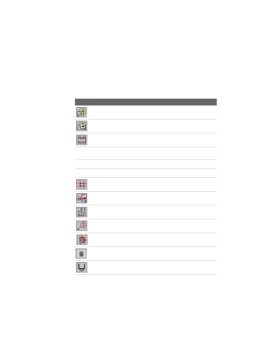
Command Summary
The following is a list of the AutoCAD Mechanical 6 commands, the
associated toolbutton, and a brief description of each. This list does not
contain the commands for AutoCAD 2002. For more information about the
commands, see the option, Commands in Alphabetical Order, in the Help.
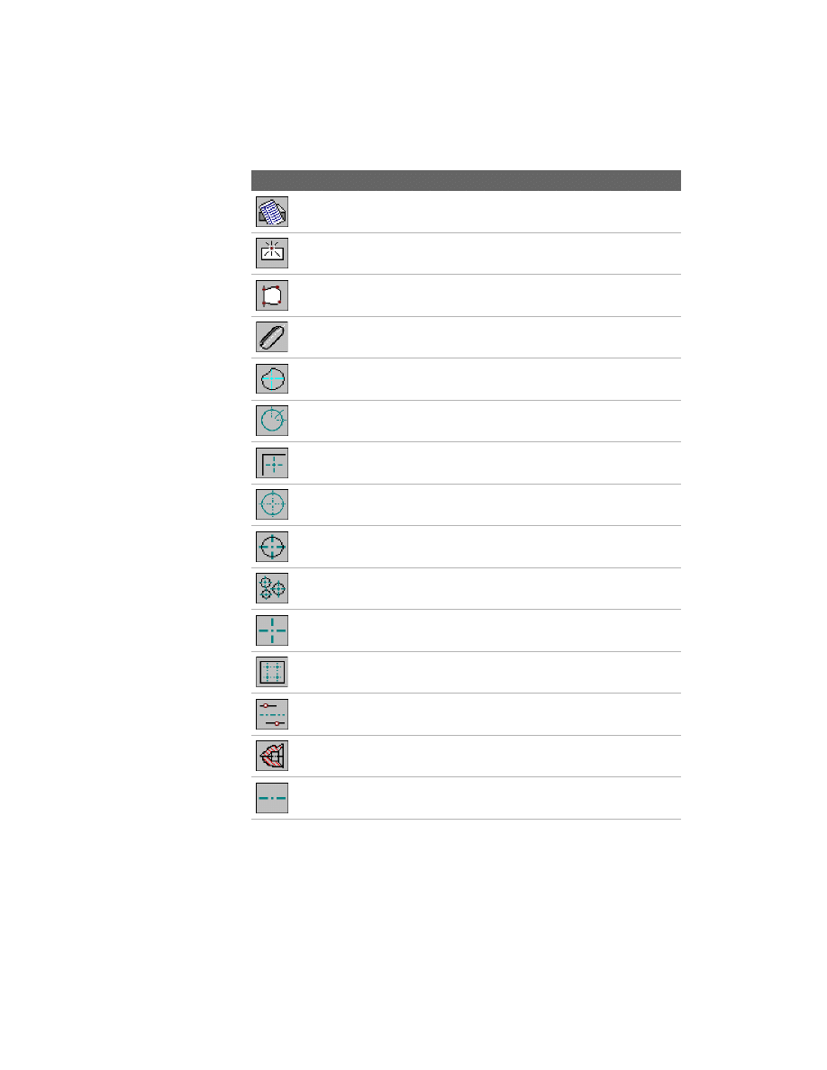
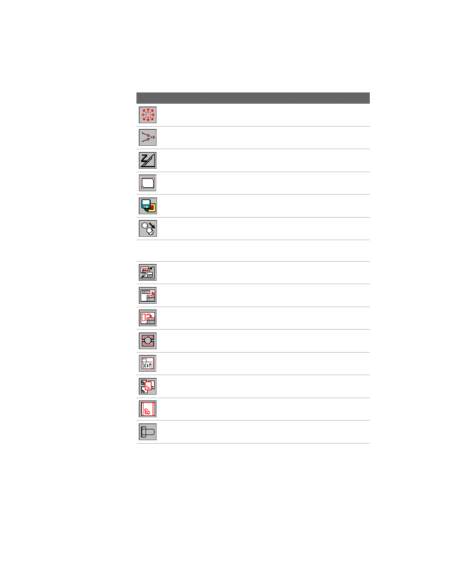
Toolbutton Command Name
Description
AM2DHIDE
Hides invisible edges
AM2DHIDEDIT
Edits existing hide situations
AMADJRINGS2D
Creates an adjusting ring on a shaft
AMANALYSEDWG
Creates a file in which the current layer structure
of the drawing is written
AMASSOHATCH
Suits an existing hatch to a changed contour
AMATTACHSYM
Displays or attaches non-attached symbols
AMAUTOCLINES
Automatically creates construction lines on
selected drawing elements
AMAUTODETAIL
Creates an external detail drawing (xref) of
selected elements from an assembly drawing
AMAUTODIM
Creates chain, baseline, ordinate in both axes,
shaft, or symmetric dimensions
AMBALLOON
Creates and places a balloon
AMBEARCALC
Performs calculation on bearings
AMBELL2D
Selects, calculates, and inserts Belleville spring
washers
AMBHOLE2D
Creates a standard related blind hole
Command Summary
|
23
AMBOM
Creates a BOM database containing a list of
attributes
AMBREAKATPT
Breaks a line, polyline, or a spline on a specified
point
AMBROUTLINE
Draws a special spline to show the breakout
borders
AMBSLOT2D
Creates a blind slot
AMCAM
Starts the cam design and calculation routine
AMCENCRANGLE
Draws a centerline cross with an angle
AMCENCRCORNER
Draws a centerline cross in a corner
AMCENCRFULLCIRCLE Draws a centerline cross on a circle
AMCENCRHOLE
Draws a centerline cross with a hole
AMCENCRINHOLE
Draws a centerline cross in a hole
AMCENCROSS
Draws a centerline cross
AMCENCRPLATE
Draws a centerline cross on a plate
AMCENINBET
Draws a centerline in between two lines
AMCENTERHOLE2D
Creates a centerhole
AMCENTLINE
Draws a centerline
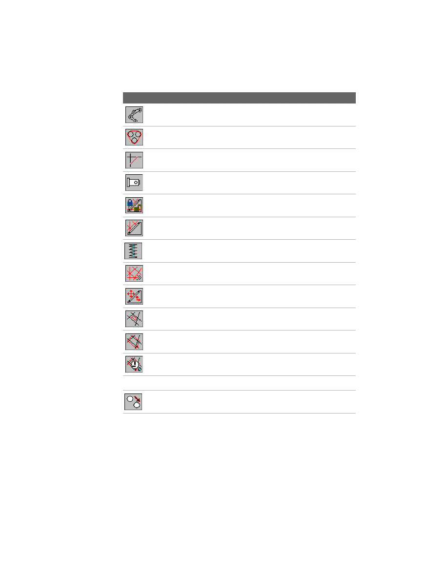
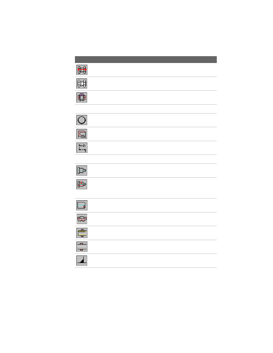
Toolbutton Command Name
Description
24
|
Chapter 2
Features and Commands
AMCHAINDRAW
Draws chain or belt links
AMCHAINLENGTHCAL Determines the tangent definition between
sprockets/pulleys
AMCHAM2D
Bevels the edges of objects
AMCLEVISPIN2D
Creates a clevis pin
AMCLINEL
Locks or unlocks the construction line layer
AMCLINEO
Switches construction lines on/off
AMCOMP2D
Selects, calculates, and inserts compression
springs.
AMCONSTLINES
Draws construction lines
AMCONSTSWI
Switches construction lines between lines and
rays
AMCONTIN
Displays the inner contour of an object
AMCONTOUT
Displays the outer contour of an object
AMCONTRACE
Traces all points of a contour
AMCONVDWG
Converts the current drawing
AMCOPY
Makes copies of one or multiple selected
objects.
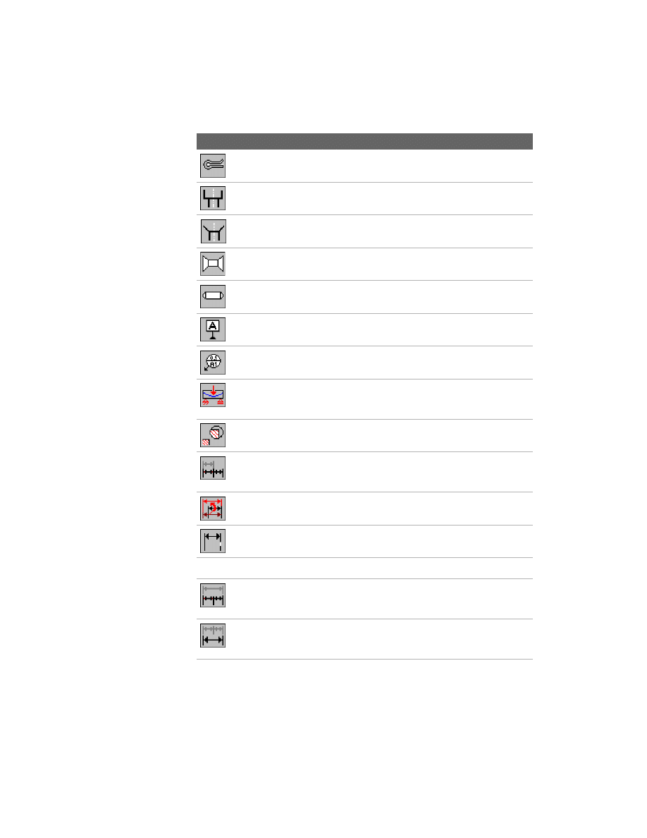
Toolbutton Command Name
Description
Command Summary
|
25
AMCOTTERPIN2D
Creates a cotter pin
AMCOUNTB2D
Creates a standard related counterbore
AMCOUNTS2D
Creates a standard related countersink
AMCRIVET2D
Creates a countersunk rivet
AMCYLPIN2D
Creates a cylindrical pin
AMDATUMID
Creates a datum identifier symbol
AMDATUMTGT
Creates and edits a datum target symbol
AMDEFLINE
Calculates the deflection line or moment line of
an object that has various force elements acting
on it
AMDETAIL
Enlarges selected parts of a drawing
AMDIMALIGN
Aligns linear, rotated, aligned, ordinate, or
angular dimensions that have a base dimension
of the same type
AMDIMARRANGE
Rearranges individual dimensions that lie along
one axis, in respect to a reference point
AMDIMBREAK
Creates breaks in an existing dimension
AMDIMFORMAT
Modifies dimensions in drawing mode
AMDIMINSERT
Edits linear, aligned, rotated, and angular
dimensions by inserting new dimensions of the
same type simultaneously
AMDIMJOIN
Edits linear, aligned, and angular (3-point or 2-
line) dimensions by joining similar dimensions
into a single dimension
Toolbutton Command Name
Description
26
|
Chapter 2
Features and Commands
AMDIMMEDIT
Edits multiple dimensions at the same time
AMDIMSTRETCH
Shortens or lengthens linear or symmetric
dimensions
AMDRBUSH2D
Creates a single drill bushing
AMDRBUSHHOLE2D
Creates a drill bushing and the corresponding
hole
AMEDGESYM
Creates edge symbols
AMEQUATEDIT
Generates and organizes equations
AMERASEALLCL
Erases all construction lines
AMERASECL
Erases selected construction lines
AMEXT2D
Selects, calculates, and inserts extension springs.
AMEXTHREAD2D
Creates an external thread
AMFCFRAME
Creates feature control frame symbols
AMFEA2D
Calculates stress and deformation in a plane for
plates with a given thickness or in a cross section
with individual forces and stretching loads
AMFEATID
Creates feature identifier symbols
AMFILLET2D
Rounds and fillets the edges of objects
AMFITSLIST
Puts existing fits and their respective dimension
values into a list and inserts this fits list into your
drawing
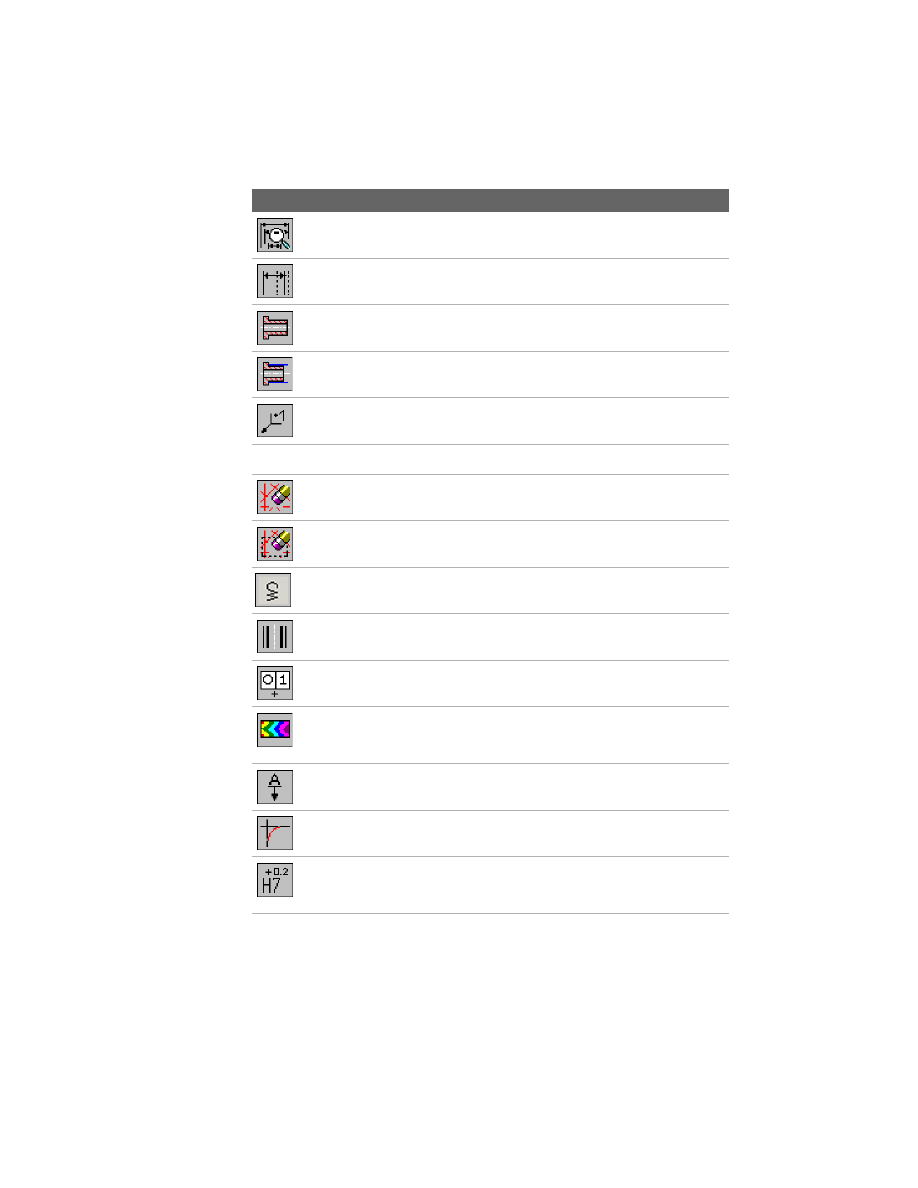
Toolbutton Command Name
Description
Command Summary
|
27
AMGROOVE2D
Inserts a retaining ring/circlip with the
appropriate groove in a shaft
AMGROOVESTUD2D
Creates a grooved drive stud
AMHATCH_135_11
Creates a 135-degree and 11 mm/0.4 inch
hatch
AMHATCH_135_2
Creates a 135-degree and 2.7 mm/0.11 inch
hatch
AMHATCH_135_4
Creates a 135-degree and 4.7 mm/0.19 inch
hatch
AMHATCH_45_13
Creates a 45-degree and 13 mm/0.5 inch hatch
AMHATCH_45_2
Creates a 45-degree and 2.5 mm/0.1 inch hatch
AMHATCH_45_5
Creates a 45-degree and 5 mm/0.22 inch hatch
AMHATCH_DBL
Creates a double hatch of 45- and 135-degree
and 2.3 mm/0.09 inch
AMHELP
Displays the online help
AMHOLECHART
Creates coordinate dimensions for holes in a
work piece and generates hole charts
AMINERTIA
Carries out the following tasks: center of gravity,
directions of the main axes moment, moments
of inertia, effective moment of inertia, deflection
angle
AMINERTIAPROF
Calculates the moment of inertia for cross
sections of cylinders, hollow cylinders,
rectangular prisms, or hollow rectangular prisms
AMJOIN
Joins different entities
AMLANGCONV
Translates text strings in your drawing into
another language
Toolbutton Command Name
Description
28
|
Chapter 2
Features and Commands
AMLANGTEXT
Displays and uses text from the Language
Converter
AMLAYER
Manages the layer system
AMLAYINVO
Switches invisible lines on/off
AMLAYMOVE
Moves lines to another layer
AMLAYMOVEPL
Moves lines to parts layers
AMLAYMOVEWL
Moves lines to working layers
AMLAYPARTO
Switches standard parts on/off
AMLAYPARTREFO
Switches part reference on/off
AMLAYRESET
Resets all layers
AMLAYTIBLO
Switches the border and title block on/off
AMLAYVISENH
Specifies the layer group setting during a
working session
AMLAYVPO
Switches viewports on/off
AMLGMOVE
Moves elements in a selection set to a specific
layer group
AMLIBRARY
Displays the Library dialog box
AMLUBRI2D
Creates a lubricator
AMMCONTV
Makes a contour visible
Toolbutton Command Name
Description
Command Summary
|
29
AMMIGRATEBB
Converts infopoints, position numbers, and
parts lists (on a drawing) from Genius 13/Genius
14 to AutoCAD Mechanical 6 format
AMMIGRATESYM
Converts all symbols from Genius 13/14 to
AutoCAD Mechanical 6 format
AMNOTE
Describes holes and fits, and creates notes to the
drawing with a leader
AMNUT2D
Creates a nut
AMOFFSET
Creates new objects at specified distances from
an existing object or through a specified point
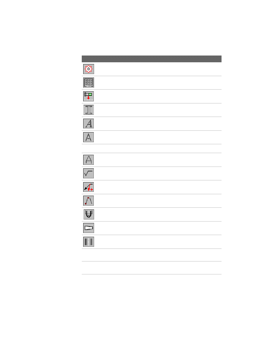
AMOPTIONS
Sets configurations
AMPARTLIST
Creates and places a parts list in a drawing
AMPARTREF
Creates part references
AMPARTREFEDIT
Edits part reference data
AMPLBEAR2D
Inserts a plain bearing on a shaft or in a housing
AMPLOTDATE
Inserts the current date in the lower right corner
of the title block
AMPLRIVET2D
Creates a plain rivet
AMPLUG2D
Creates a plug
AMPOWERCOPY
Copies an object with its internal information to
another position in the drawing
AMPOWERDIM
Creates dimensions, or assigns tolerances or fits
to any of these dimensions
Toolbutton Command Name
Description
30
|
Chapter 2
Features and Commands
AMPOWERDIM_ANG
Creates angular dimensions, or assigns
tolerances or fits to dimension
AMPOWEREDIT
Starts the command with which the selected
object was created to edit the object
AMPOWERERASE
Deletes selected objects
AMPOWERRECALL
Starts the command with which the selected
object was created, to create a new object
AMPOWERSNAP
Sets object snap modes, polar snap, and filters
for object snaps
AMPOWERVIEW
Creates top or side views of standard parts
AMPROJO
Creates a projection crosshairs used for creating
orthographic views
AMPSNAP1
Sets user-defined snap settings on tab 1
AMPSNAP2
Sets user-defined snap settings on tab 2
AMPSNAP3
Sets user-defined snap settings on tab 3
AMPSNAP4
Sets user-defined snap settings on tab 4
AMPSNAPCEN
Snaps the rectangle center
AMPSNAPFILTERO
Switches the entity filter on or off
AMPSNAPMID
Snaps to the middle of two points
AMPSNAPREF
Snaps to a reference point
Toolbutton Command Name
Description
Command Summary
|
31
AMPSNAPREL
Snaps to a relative point
AMPSNAPVINT
Snaps to a virtual intersection point of two lines
AMPSNAPZO
Switches snapping of the Z coordinate on or off
AMRECTANG
Creates a rectangle by defining its starting and
endpoint
AMREFCLOSE
Saves REFEDIT working set changes
AMREFCOPY
Copies objects from other blocks to the
REFEDIT working set
AMRESCALE
Rescales dimensions and symbols in model and
layout
AMREV
Switches revision lists on or off
AMREVLINE
Inserts a revision list into a drawing or adds an
additional revision line to an existing revision list
AMREVUPDATE
Updates revision lists
AMROLBEAR2D
Inserts a radial or axial roller bearing on a shaft
or in a housing
AMSCALEXY
Allows scaling for entities in X and Y direction
AMSCAREA
Creates a scale area in model space
AMSCMONITOR
Views and edits the scale of scale areas or
viewports
AMSCREW2D
Creates a screw or bolt
Toolbutton Command Name
Description
32
|
Chapter 2
Features and Commands
AMSCREWCALC
Checks a screw connection
AMSCREWCON2D
Opens the Screw Connection dialog box
AMSCREWMACRO2D
Opens the Screw Assembly Templates dialog
box
AMSCRIPT
Generates scripts
AMSEALRING2D
Creates a sealing ring for use under a plug
AMSEALS2D
Inserts a seal/O-ring with the appropriate
groove in a shaft
AMSECTIONLINE
Creates cutting plane lines
AMSETUPDWG
Sets up a drawing
AMSHAFT2D
Creates rotationally symmetric shaft parts and
inner and outer shaft contours
AMSHAFTCALC
Calculates deflection line, bending moment,
torsion moment, supporting force, torque
rotation angle, equivalent tension, and the
safety factor of shafts
AMSHAFTEND
Creates a zigzag line, a free-hand line, or loop to
represent a shaft end
AMSHAFTKEY2D
Inserts a parallel or woodruff key with the
appropriate keyseat in a shaft
AMSHAFTLNUT2D
Creates a shaft lock nut including the lock
washer and inserts both in a shaft
AMSHIMRING2D
Creates a shim ring on a shaft
AMSIMPLEWELD
Creates seam and fillet simple welds
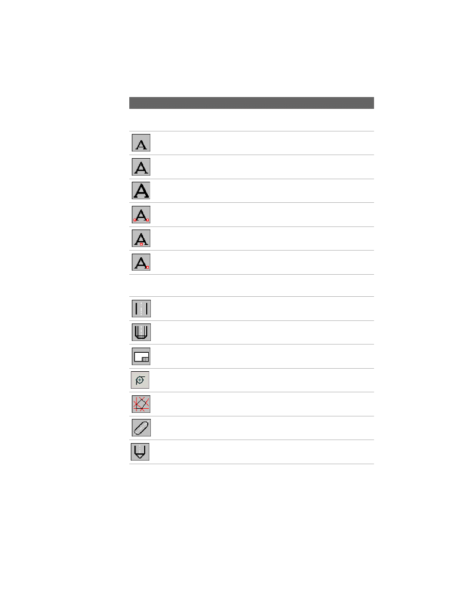
Toolbutton Command Name
Description
Command Summary
|
33
AMSPROCKET
Draws sprockets or pulleys
AMSTDPLIB
Opens the Parts Database dialog box for editing
and selection
AMSTDPREP
Changes the representation of a standard part
AMSTLSHAP2D
Creates a steel shape
AMSTYLEITAL
Changes the text style to italic
AMSTYLESIMP
Changes the text style to simplex
AMSTYLESTAND
Changes the text style to standard
AMSTYLETXT
Changes the text style to TXT
AMSURFSYM
Creates surface texture symbols
AMSYMLEADER
Appends/removes a leader
AMSYMLINE
Draws symmetrical lines
AMTAPBHOLE2D
Creates a standard related tapped blind hole
AMTAPERPIN2D
Creates a taper pin
AMTAPTHOLE2D
Creates a standard related tapped through hole
AMTBFULL
Displays the Mechanical Toolbar at the left side
and the Snap Toolbar at the right side
AMTBLEFT
Places the Mechanical Express Toolbar at the left
side
Toolbutton Command Name
Description
34
|
Chapter 2
Features and Commands
AMTBRIGHT
Places the Mechanical Express Toolbar at the
right side
AMTEXT3
Inserts mtext with 3.5 mm height
AMTEXT5
Inserts mtext with 5 mm height
AMTEXT7
Inserts mtext with 7 mm height
AMTEXTCENT
Centers text horizontally and vertically
AMTEXTHORIZ
Centers text horizontally
AMTEXTRIGHT
Aligns mtext to the right
AMTEXTSIZE
Sets text to its default size in model space and
layout, and defines a height for an inserted text
AMTHOLE2D
Creates a standard related through hole
AMTHREADEND2D
Creates a thread end
AMTITLE
Inserts a title block and a drawing border
AMTOR2D
Selects, calculates, and inserts torsion springs.
AMTRCONT
Traces contours on construction lines
AMTSLOT2D
Creates a standard related through slot.
AMUBHOLE2D
Creates a user-defined blind hole
Toolbutton Command Name
Description
Command Summary
|
35
AMUBSLOT2D
Creates a user-defined blind slot
AMUCOUNTB2D
Creates a user-defined counterbore
AMUCOUNTS2D
Creates a user-defined countersink
AMUNDERCUT2D
Creates an undercut on a shaft
AMUSERHATCH
Inserts a user-defined hatch
AMUTHOLE2D
Creates a user-defined through hole
AMUTSLOT2D
Creates a user-defined slot
AMVIEWALL
Zooms the view according to the limits
AMVIEWCEN
Zooms the center of the viewports
AMVIEWLL
Zooms the predefined lower-left quarter of the
drawing
AMVIEWLR
Zooms the predefined lower-right quarter of the
drawing
AMVIEWUL
Zooms the predefined upper-left quarter of the
drawing
AMVIEWUR
Zooms the predefined upper-right quarter of
the drawing
AMVPORT
Creates a viewport in layout
AMVPORTAUTO
Creates viewports automatically
AMVPZOOMALL
Resets the viewports to the default scale factor
Toolbutton Command Name
Description
36
|
Chapter 2
Features and Commands
AMWASHER2D
Creates a washer
AMWELDSYM
Creates welding symbols
AMXREFSET
Controls the representation of xrefs
AMZIGZAGLINE
Draws zigzag lines
AMZOOMVP
Displays a selected area in another viewport
Toolbutton Command Name
Description

37
In This Chapter
3
New and Revised
Commands
This chapter contains information about the new and
revised commands and functions in AutoCAD
®
Mechanical 6.
■
New and Revised Commands
■
New functions
aug_03_ss2.fm Page 37 Friday, June 21, 2002 11:50 AM
38
|
Chapter 3
New and Revised Commands
New and Revised Command Summary
AutoCAD Mechanical 6 includes a number of new commands and
commands revised from the previous version. This is an overview of the most
important changes in AutoCAD Mechanical 6.
For more information about all features, see “Key Features in AutoCAD
Mechanical 6” on page 18.
AMBALLOON
Menu
Annotate ➤ Parts List Tools ➤ Balloons
Command
AMBALLOON
■
Improved collection of different balloon types.
AMBELL2D
Menu
Content ➤ Springs
Command
AMBELL2D
■
Spring selection from Standard Parts Database.
■
Every spring type has its own command.
■
New user interface.
■
Changed insertion sequence for simplified handling.
■
Former spring blocks changed to custom entities.
Creates and places balloons.
Selects, calculates, and inserts Belleville spring washers.
aug_03_ss2.fm Page 38 Friday, June 21, 2002 11:50 AM
New and Revised Command Summary
|
39
AMBOM
Menu
Annotate ➤ Parts List Tools ➤ BOM Database
Command
AMBOM
■
Grouped by functionality in Parts List.
■
Item number enhancement (text, increment, leading zero)
■
Set values improvement (ascending text for item).
■
Grid lines on/off.
■
Improved cuts list creation.
AMCAM
Menu
Content ➤ Cams
Command
AMCAM
■
Completely new User Interface.
■
Supports circular, cylindrical, and linear cams.
■
Supports follower design and calculation.
■
Enables strength calculations of the cam.
■
Supports polynominals, not only fifth degree.
■
Calculation of various motion curves is possible.
■
Generates 3D solids for 3D representation of the cam.
■
Enhanced export functions.
AMCOMP2D
Menu
Content ➤ Springs
Command
AMCOMP2D
■
Spring selection from Standard Parts Database.
■
Every spring type has it’s own command.
■
New user interface.
■
Changed insertion sequence for simplified handling.
■
Former spring blocks changed to custom entities.
Creates a BOM database containing a list of attributes.
Calculates various cams.
Selects, calculates, and inserts compression springs.
aug_03_ss2.fm Page 39 Friday, June 21, 2002 11:50 AM
40
|
Chapter 3
New and Revised Commands
AMEXT2D
Menu
Content ➤ Springs
Command
AMEXT2D
■
Spring selection from Standard Parts Database.
■
Every spring type has it’s own command.
■
New user interface.
■
Changed insertion sequence for simplified handling.
■
Former spring blocks changed to custom entities.
AMHOLECHART
Menu
Annotate ➤ Hole Chart
Command
AMHOLECHART
■
New, and improved user interface.
■
Changed hole chart from block to custom entities.
■
Migration of Genius hole chart to AutoCAD Mechanical 6 hole chart.
■
Hole chart is standard dependent.
■
Allows user-defined modifications of hole charts.
AMMANIPULATE
Menu
Modify ➤ Power Manipulator
Command
AMMANIPULATE
■
User-friendly, modeless dialog.
■
Supports tooltips.
■
Redesigned Properties dialog.
Selects, calculates, and inserts extension springs.
Creates coordinate dimensions for holes in a work piece and generates hole charts.
Dynamically moves and rotates selected geometry along/around the X, Y, Z axes.
aug_03_ss2.fm Page 40 Friday, June 21, 2002 11:50 AM
New and Revised Command Summary
|
41
AMNOTE
Menu
Annotate ➤ Note
Command
AMNOTE
■
New dialog, which displays all variables of features.
■
Can be attached to all features (standard parts, holes, and so on).
■
Allows the creation of templates specific to a feature type.
■
Simplified insertion of special characters.
■
Applying of different dimension styles is possible.
AMOPTIONS
Menu
Assist ➤ Mechanical Options
Command
AMOPTIONS
■
New, Hole Chart entry in Standard Settings.
■
Note Template added to Mechanical Options.
AMPARTLIST
Menu
Annotate ➤ Parts List Tools ➤ Parts List
Command
AMPARTLIST
■
New Grouping tool, which compares items by key definitions and groups
them according to the selection.
■
Parts List allows different increments.
■
Grid lines on/off.
■
Item columns can be changed from numeric entries to text entries.
Describes holes and fits, and creates notes to the drawing with a leader.
Sets the configuration
Creates and places a parts list in a drawing.
aug_03_ss2.fm Page 41 Friday, June 21, 2002 11:50 AM
42
|
Chapter 3
New and Revised Commands
AMSTLSHAP2D
Menu
Content ➤ Steel Shapes
Command
AMSTLSHAP2D
■
Simplified representation of 2D steel shapes.
AMTOR2D
Menu
Content ➤ Springs
Command
AMTOR
■
Spring selection from Standard Parts Database.
■
Every spring type has it’s own command.
■
New user interface.
■
Changed insertion sequence for simplified handling.
■
Former spring blocks changed to custom entities.
SAVEAS
Menu
File ➤ SaveAs
Command
SAVEAS
■
Allows saving of a AutoCAD Mechanical 6 file format to a AutoCAD
Mechanical 2000i format.
Creates a 2D steel shape.
Selects, calculates, and inserts torsion springs.
Saves a file into a different file format.
aug_03_ss2.fm Page 42 Friday, June 21, 2002 11:50 AM
Document Outline
- Part I Getting Started with AutoCAD Mechanical
- Chapter 1 Where to Start
- About AutoCAD Mechanical
- Modeling with AutoCAD Mechanical 6
- Starting AutoCAD Mechanical
- Where to Go First
- Accessing AutoCAD Mechanical Commands
- Migration Assistance
- AutoCAD Mechanical Today
- Printed and Online Manuals
- AutoCAD Mechanical Help
- Product Support Assistance in Help
- Learning and Training Resources
- Internet Resources
- Typographical Conventions
- Chapter 2 Features and Commands
- Chapter 3 New and Revised Commands
- Chapter 1 Where to Start
Wyszukiwarka
Podobne podstrony:
Part I Getting Started
Borland Delphi Magazine Getting Started With Sql Part 2
Getting Started
getting started IAOTAGZXANHHC6G Nieznany
(ebook pdf) Matlab Getting started
1 3 Getting started with Data Studio Lab
Getting Started with PostHASTE
Packt Publishing Getting Started with Backbone Marionette (2014)
Getting Started
ANSYS Getting Started Tutorial Workbench
chinas southwest 3 getting started
1 2 Getting started (2)
Neuro Solutions 5 Getting Started Manual
mr zr getting started
Matlab Getting Started
więcej podobnych podstron