91-622
Removal/installation of control unit for airbags and belt
tensioners (from 09/87 onwards)
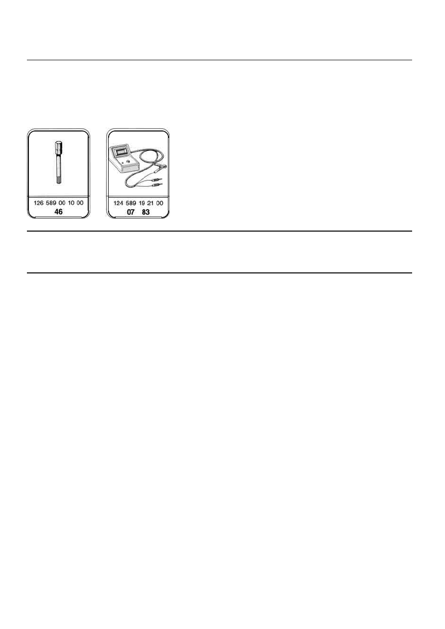
Special tools
Commercially available tools
Ratchet (1/4")
Part No. 415
e.g.
Eduard Wille GmbH
Connector (1/4")
Part No. 412
Postfach 12 01 03
D-5600 Wuppertal 12
Testing
-------------------------------
After completing operations on the driver's
airbag/belt tensioner restraint system, the
system must be tested with an impulse
display.
The test procedure is described at the end of
the job number.
Copyright Daimler AG 25.12.14 G/08/07. Ten wydruk WIS nie jest obj
ę
ty funkcj
ą
aktualizacji.
strona 1
P91-0023-61
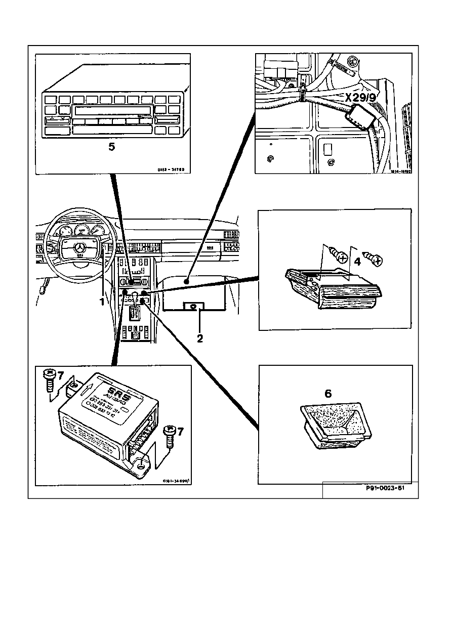
Removal
Ignition (1)
Switch off.
Negative battery terminal
Disconnect and insulate.
Passenger's footwell floormat
Remove.
Plastic nut on footrest (2), wrench size 8
Remove.
Red 10-pin plug, airbag (X29/9)
Disconnect.
Ashtray
Remove
Two cross-slot screws in ashtray housing (4)
Remove
Copyright Daimler AG 25.12.14 G/08/07. Ten wydruk WIS nie jest obj
ę
ty funkcj
ą
aktualizacji.
strona 2
Ashtray housing and storage tray (6)
Remove.
Radio (5)
Remove.
Plug connector on control unit
Disconnect.
Two cross-slot screws on control unit (7)
Remove.
Control unit
Remove.
Installation note
Arrow on control unit must point towards
front of vehicle.
Install in reverse order.
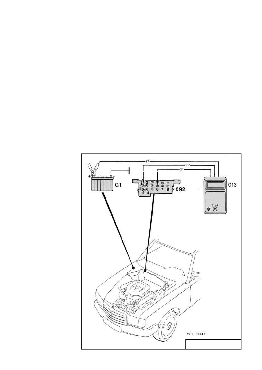
Testing after control unit replacement
Impulse counterconnecting
diagram, Model 126
013
Impulse counter
G1
Battery
X92
Test connection for
8-pole diagnostics
(flasher code)
1913-15443
A diagnostic program is incorporated in the
Copyright Daimler AG 25.12.14 G/08/07. Ten wydruk WIS nie jest obj
ę
ty funkcj
ą
aktualizacji.
strona 3

control unit which checks both the unit itself
and the airbag system components. If a fault
is identified, either the control lamp (A1e15)
will not go out after 4 seconds or it will come
on when the vehicle is being driven. The fault
is memorized and can be checked as an
impulse display via control lamp (A1e15) or
digitally by means of an impulse counter.
Note on impulse display
The impulse counter display panel shows
numbers 1-10.
Number 1 signifies that no faults are stored
in the system memory. All the other digits are
assigned to specific faulty circuits. If more
than one fault is present in the system, the
fault with the lowest impulse number is
indicated first.
If, after connection, the LED U-Batt
lights up, the impulse counter and power
supply to the impulse counter are in
order.
When, during testing, the first number
reappears after at least two or more
impulse displays (digits) all the faults
have been indicated.
Impulse display diagnosis
Connect impulse counter as shown in
connecting diagram.
Note
The LED U-Batt display in the display
panel must light up.
Switch on the ignition.
Copyright Daimler AG 25.12.14 G/08/07. Ten wydruk WIS nie jest obj
ę
ty funkcj
ą
aktualizacji.
strona 4

Operate start button from 2 to 4 seconds.
Display 1 means no faults in system.
If another number appears, rectify fault
in accordance with Trouble Diagnosis
schedule.
Copyright Daimler AG 25.12.14 G/08/07. Ten wydruk WIS nie jest obj
ę
ty funkcj
ą
aktualizacji.
strona 5
Wyszukiwarka
Podobne podstrony:
0620 Removal and installation of control unit for airbag seat belt tensioner Model 126 (to 08 87)
Removal and installation of interior temperature sensor Heating, ventilation Model 126 A To 06 81,
Design and implementation of Psychoacoustics Equalizer for Infotainment
Chak, Leung Shyness and Locus of Control as Predictors of Internet Addiction and Internet Use
G 2 0 DOHC ECTS Removal and Installation doc
Fences Types and Installation of Wooden Fence Posts
COMBAT AND OPERATIONAL STRESS CONTROL MANUAL FOR LEADERS AND SOLDIERS
Rewicz, Tomasz i inni Isolation and characterization of 8 microsatellite loci for the ‘‘killer shri
A dynamic model for solid oxide fuel cell system and analyzing of its performance for direct current
transmission removal and installation at
0400 Function description electrical function of control unit Auxiliary heater Models 124, 126, 201
0710 Test program for airbag and seat belt tensioner A General, B Fault diagnosis with the impulse
SMeyer WO8901464A3 Controlled Process for the Production of Thermal Energy from Gases and Apparatus
9 Guidelines for Fiber Optic Design and Installation
Development of wind turbine control algorithms for industrial use
Control of a 4 leg Inverter for Standalone Photovoltaic Systems
więcej podobnych podstron